Embed Size (px)
Citation preview
Contents
Application Note - Using Modbus With Conext™ RL Inverters
976-2110-01-01Revision A
Section Page
Introduction 3
Overview 3
Key Points 3
Related Documents 4
Modbus Physical Layer 5
RJ-45 Connection 5
Termination Resistor 6
Communication parameters 7
Inverter Configuration 9
Setting the Modbus Slave Address (Inverter ID) 9
Modbus Logical Layer 11
Modbus Logical Layer 11
Modbus Packet Structure 11
Slave address field 11
Function field 11
Data field 11
Error check field (checksum) 12
Packet communications 12
Modbus functions supported by the inverter 12
Function 03: Read Holding Registers 12
Function 16: Preset Multiple Registers 13
Function 43: Device Discovery 14
Broadcasts 17
Modbus Data Types 18
16-bit integer format 18
Application Note - Using Modbus With Conext™ RL Inverters
32-bit integer format 19
8-bit Unsigned Character Format 19
Modbus Error Responses 20
Function Code Field 20
Data Field 20
Modbus Error Response Example 21
Conext RL Modbus Map 22
Modbus Address 22
Modbus Register Description 22
Modbus Register Access type 22
Modbus Register Units 22
Modbus Register Size 23
Invalid Registers 23
Modbus Map 23
Appendix A: CRC-16 calculation 45
Pseudocode For CRC-16 Generation 46
Appendix B: Leading and Lagging Power Factors 47
DANGER
HAZARD OF FIRE, ARC FLASH, OR ELECTRIC SHOCK FROM MULTIPLE SOURCES
• This Application Note is in addition to, and incorporates by reference, the installation and operation manual for the Conext™ RL 3000 E, 4000 E, and 5000 E photovoltaic grid tie inverters. Before reviewing this Application Note you must read the Conext RL installation and operation manual (part number:975-0687-01-01). Unless specified, information on safety, specifications, installation, and operation is as shown in the primary documentation received with the product. Ensure you are familiar with that information before proceeding.
• To be installed and serviced only by qualified personnel.
• This document is intended for use by qualified installers only.
• Before servicing, disconnect all the sources and wait at least one minute.
Failure to follow these instructions will result in death or serious injury.
Section Page
976-2110-01-01 Revision A 2
Application Note - Using Modbus With Conext™ RL Inverters
Introduction
Overview
Modbus is a simple and robust open communication protocol used to provide interoperability between products from many different vendors. The purpose of this application note is to provide a brief overview of the Modbus hardware and software implementation of the:
Conext RL 3000 E-S (part number PVSNVC3000S and PVSNVC3000ST)
Conext RL 3000 E (part number PVSNVC3000 and PVSNVC3000T)
Conext RL 4000 E-S (part number PVSNVC4000S and PVSNVC4000ST)
Conext RL 4000 E (part number PVSNVC4000 and PVSNVC4000T)
Conext RL 5000 E-S (part number PVSNVC5000S and PVSNVC5000ST)
Conext RL 5000 E (part number PVSNVC5000 and PVSNVC5000T)
photovoltaic grid tie inverters, so that you can quickly and easily interface the inverter with any third-party Modbus devices.
The Inverter part numbers with suffix “T” (eg: PVSNVC3000ST) are intended to be installed
in Thailand.
The inverter performs Modbus communications according to the Modbus register definition in Table 23. It is assumed that you are familiar with the Modbus protocol and with serial communications in general.
Key Points
The inverter is capable of communicating via the RS-485 serial communication standard. The RS-485 medium allows for multiple devices on the same serial bus network.
All communications on the network conform to a Master/Slave scheme. In this scheme, information and data are transferred between a Modbus Master device and up to 31 Slave devices.
The Master device initiates and controls all the information transfer on the Modbus serial bus network. There may be only one master for any Modbus network.
A Slave device never initiates a communication sequence, and must remain silent unless addressed specifically by the Master.
All the communication activity on the Modbus serial bus network occurs in the form of packets. A packet is a serial string of up to 255 8-bit bytes.
All packets transmitted by the Master are requests. All the packets transmitted by a Slave are responses.
At most, one Slave can respond to a single request from a Master.
The Conext RL 3000 E, 4000 E, and 5000 E photovoltaic grid tie inverters support only the Modbus/RTU protocol.
3 976-2110-01-01 Revision A
Application Note - Using Modbus With Conext™ RL Inverters
Related Documents
Table 1 Related documents
Document reference Document title Document number Version
1 Modbus Application Protocol Specification
From www.modbus.org
1.1b
2 Conext RL 3000 E, 4000 E, and 5000 E Installation and Operation Manual
975-0687-01-01 C
976-2110-01-01 Revision A 4
Application Note - Using Modbus With Conext™ RL Inverters
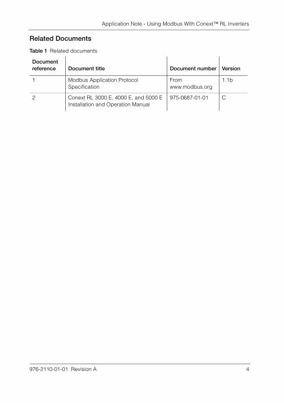
Modbus Physical LayerThe Conext RL inverter supports the Modbus communication protocol via an RS485 interface. An RJ-45 wiring interface is supported. The module is shown in Figure 1.
RJ-45 Connection
The RS-485 bus is a multi-drop bus implemented as a daisy chain. The RJ-45 connector is provided with two ports to allow ease of daisy chaining. Either port can be connected to the upstream or downstream devices.
A standard Ethernet (straight-through) patch cable may be used to connect to the upstream and downstream devices. Ethernet cross-over cables must not be used.
The RJ45 connector provides D+, D-, and signal Ground connections.
The pin definitions of the RJ-45 connection are shown in Table 2. For the location of pin 8, see Figure 2.
Figure 1 Communication module
RJ45 connectors(RS485)
Termination resistor
5 976-2110-01-01 Revision A
Application Note - Using Modbus With Conext™ RL Inverters
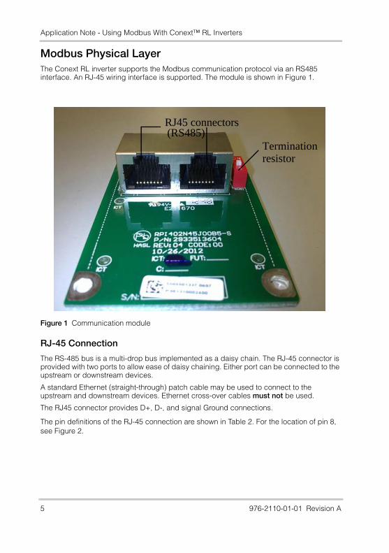
For pin numbering, see
Termination Resistor
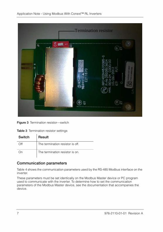
You must enable the termination resistors if the inverter is on the end of the Modbus device chain. To do this, use a DIP switch on the communication interface board. If the inverter is the first or the last device of the RS485-chain, set the termination resistor to on; otherwise, set it to off.
The location of the termination resistor is shown in Figure 3. The settings are shown in Table 3.
Table 2 RJ-45 pin definitions
Pin Function
4 DATA+
5 DATA-
7 NC (Not connected)
8 Modbus ground
Figure 2 pin numbering
976-2110-01-01 Revision A 6
Application Note - Using Modbus With Conext™ RL Inverters
Communication parameters
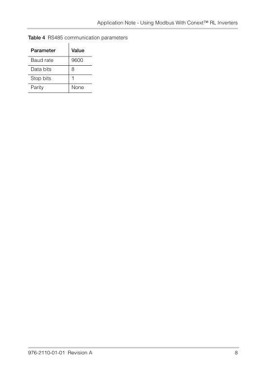
Table 4 shows the communication parameters used by the RS-485 Modbus interface on the inverter.
These parameters must be set identically on the Modbus Master device or PC program used to communicate with the inverter. To determine how to set the communication parameters of the Modbus Master device, see the documentation that accompanies the device.
Figure 3 Termination resistor—switch
Table 3 Termination resistor settings
Switch Result
Off The termination resistor is off.
On The termination resistor is on.
Termination resistor
7 976-2110-01-01 Revision A
Application Note - Using Modbus With Conext™ RL Inverters
Table 4 RS485 communication parameters
Parameter Value
Baud rate 9600
Data bits 8
Stop bits 1
Parity None
976-2110-01-01 Revision A 8
Application Note - Using Modbus With Conext™ RL Inverters
Inverter Configuration
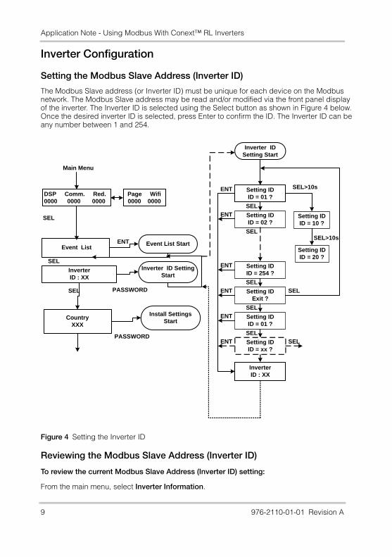
Setting the Modbus Slave Address (Inverter ID)
The Modbus Slave address (or Inverter ID) must be unique for each device on the Modbus network. The Modbus Slave address may be read and/or modified via the front panel display of the inverter. The Inverter ID is selected using the Select button as shown in Figure 4 below. Once the desired inverter ID is selected, press Enter to confirm the ID. The Inverter ID can be any number between 1 and 254.
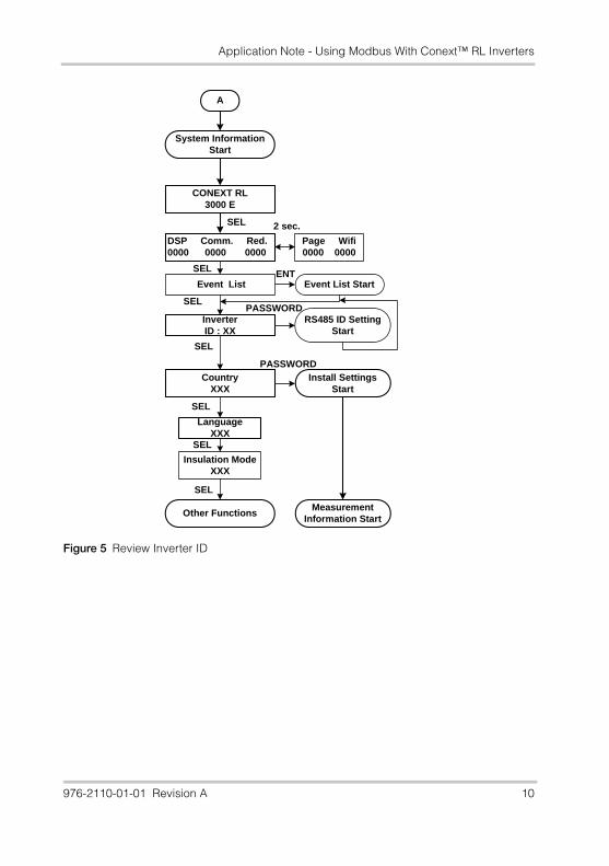
Reviewing the Modbus Slave Address (Inverter ID)
To review the current Modbus Slave Address (Inverter ID) setting:
From the main menu, select Inverter Information.
Figure 4 Setting the Inverter ID
Inverter ID Setting Start
Setting IDID = 01 ?
Setting IDID = 02 ?
Setting IDID = 10 ?
SEL
SEL>10s
Setting IDID = 20 ?
SEL>10sSEL
InverterID : XX
Setting IDID = 01 ?
ENT
Setting IDID = 254 ?
SEL
Setting IDExit ?
SEL
ENT
ENT
ENT
ENT SEL
SELSetting IDID = xx ?
SEL
ENT
DSP Comm. Red.0000 0000 0000
Event List
InverterID : XX
CountryXXX
Page Wifi0000 0000
SEL
SEL
SEL
Event List StartENT
Inverter ID Setting Start
Install Settings Start
Main Menu
PASSWORD
PASSWORD
9 976-2110-01-01 Revision A
Application Note - Using Modbus With Conext™ RL Inverters
Figure 5 Review Inverter ID
System Information Start
DSP Comm. Red.0000 0000 0000
Event List
InverterID : XX
CountryXXX
LanguageXXX
Insulation ModeXXX
Page Wifi0000 0000
SEL
SEL
SEL
SEL
SEL
SEL
SEL
2 sec.
Event List StartENT
RS485 ID Setting Start
Install Settings Start
Measurement Information Start
Other Functions
CONEXT RL3000 E
A
PASSWORD
PASSWORD
976-2110-01-01 Revision A 10
Application Note - Using Modbus With Conext™ RL Inverters
Modbus Logical Layer
Modbus Packet Structure
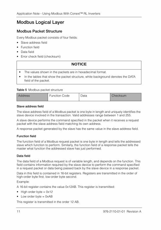
Every Modbus packet consists of four fields:
• Slave address field
• Function field
• Data field
• Error check field (checksum)
Slave address field
The slave address field of a Modbus packet is one byte in length and uniquely identifies the slave device involved in the transaction. Valid addresses range between 1 and 255.
A slave device performs the command specified in the packet when it receives a request packet with the slave address field matching its own address.
A response packet generated by the slave has the same value in the slave address field.
Function field
The function field of a Modbus request packet is one byte in length and tells the addressed slave which function to perform. Similarly, the function field of a response packet tells the master what function the addressed slave has just performed.
Data field
The data field of a Modbus request is of variable length, and depends on the function. This field contains information required by the slave device to perform the command specified in a request packet or data being passed back by the slave device in a response packet.
Data in this field is contained in 16-bit registers. Registers are transmitted in the order of high-order byte first, low-order byte second.
Example:
A 16-bit register contains the value 0x12AB. This register is transmitted:
• High order byte = 0x12
• Low order byte = 0xAB
This register is transmitted in the order 12 AB.
NOTICE
• The values shown in the packets are in hexadecimal format.
• In the tables that show the packet structure, white background denotes the DATA field of the packet.
Table 5 Modbus packet structure
Address Function Code Data Checksum
11 976-2110-01-01 Revision A
Application Note - Using Modbus With Conext™ RL Inverters
Error check field (checksum)
The checksum field lets the receiving device determine if a packet is corrupted with transmission errors. In Modbus RTU mode, a 16-bit Cyclic Redundancy Check (CRC-16) is used.
The sending device calculates a 16-bit value, based on every byte in the packet, using the CRC-16 algorithm. The calculated value is inserted in the error check field.
The receiving device performs the calculation, without the error check field, on the entire packet it receives. The resulting value is compared to the error check field. Transmission errors are indicated when the calculated checksum does not equal the checksum stored in the incoming packet. The receiving device ignores a bad packet.
For more information on CRC-16 calculations, see “Appendix A: CRC-16 calculation” on page 45.
Packet communications
This section describes the Modbus functions supported by the inverter.
Modbus functions supported by the inverter
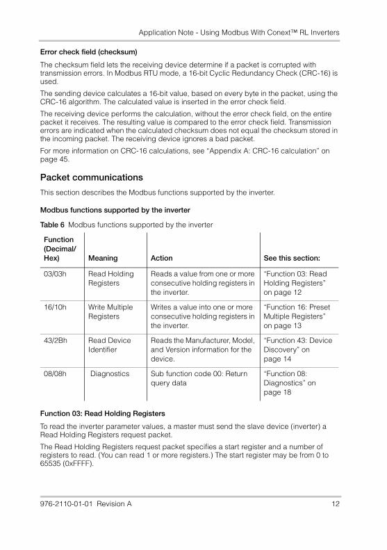
Function 03: Read Holding Registers
To read the inverter parameter values, a master must send the slave device (inverter) a Read Holding Registers request packet.
The Read Holding Registers request packet specifies a start register and a number of registers to read. (You can read 1 or more registers.) The start register may be from 0 to 65535 (0xFFFF).
Table 6 Modbus functions supported by the inverter
Function(Decimal/Hex) Meaning Action See this section:
03/03h Read Holding Registers
Reads a value from one or more consecutive holding registers in the inverter.
“Function 03: Read Holding Registers” on page 12
16/10h Write Multiple Registers
Writes a value into one or more consecutive holding registers in the inverter.
“Function 16: Preset Multiple Registers” on page 13
43/2Bh Read Device Identifier
Reads the Manufacturer, Model, and Version information for the device.
“Function 43: Device Discovery” on page 14
08/08h Diagnostics Sub function code 00: Return query data
“Function 08: Diagnostics” on page 18
976-2110-01-01 Revision A 12
Application Note - Using Modbus With Conext™ RL Inverters
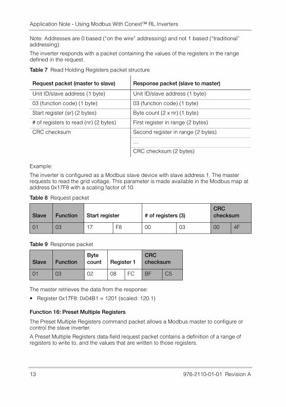
Note: Addresses are 0 based (“on the wire” addressing) and not 1 based (“traditional” addressing).
The inverter responds with a packet containing the values of the registers in the range defined in the request.
Example:
The inverter is configured as a Modbus slave device with slave address 1. The master requests to read the grid voltage. This parameter is made available in the Modbus map at address 0x17F8 with a scaling factor of 10.
The master retrieves the data from the response:
• Register 0x17F8: 0x04B1 = 1201 (scaled: 120.1)
Function 16: Preset Multiple Registers
The Preset Multiple Registers command packet allows a Modbus master to configure or control the slave inverter.
A Preset Multiple Registers data-field request packet contains a definition of a range of registers to write to, and the values that are written to those registers.
Table 7 Read Holding Registers packet structure
Request packet (master to slave) Response packet (slave to master)
Unit ID/slave address (1 byte) Unit ID/slave address (1 byte)
03 (function code) (1 byte) 03 (function code) (1 byte)
Start register (sr) (2 bytes) Byte count (2 x nr) (1 byte)
# of registers to read (nr) (2 bytes) First register in range (2 bytes)
CRC checksum Second register in range (2 bytes)
…
CRC checksum (2 bytes)
Table 8 Request packet
Slave Function Start register # of registers (3)CRC checksum
01 03 17 F8 00 03 00 4F
Table 9 Response packet
Slave FunctionByte count Register 1
CRC checksum
01 03 02 08 FC BF C5
13 976-2110-01-01 Revision A
Application Note - Using Modbus With Conext™ RL Inverters
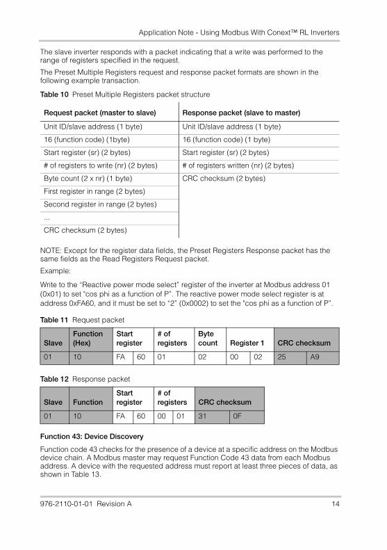
The slave inverter responds with a packet indicating that a write was performed to the range of registers specified in the request.
The Preset Multiple Registers request and response packet formats are shown in the following example transaction.
NOTE: Except for the register data fields, the Preset Registers Response packet has the same fields as the Read Registers Request packet.
Example:
Write to the “Reactive power mode select” register of the inverter at Modbus address 01 (0x01) to set "cos phi as a function of P”. The reactive power mode select register is at address 0xFA60, and it must be set to “2” (0x0002) to set the "cos phi as a function of P”.
Function 43: Device Discovery
Function code 43 checks for the presence of a device at a specific address on the Modbus device chain. A Modbus master may request Function Code 43 data from each Modbus address. A device with the requested address must report at least three pieces of data, as shown in Table 13.
Table 10 Preset Multiple Registers packet structure
Request packet (master to slave) Response packet (slave to master)
Unit ID/slave address (1 byte) Unit ID/slave address (1 byte)
16 (function code) (1byte) 16 (function code) (1 byte)
Start register (sr) (2 bytes) Start register (sr) (2 bytes)
# of registers to write (nr) (2 bytes) # of registers written (nr) (2 bytes)
Byte count (2 x nr) (1 byte) CRC checksum (2 bytes)
First register in range (2 bytes)
Second register in range (2 bytes)
...
CRC checksum (2 bytes)
Table 11 Request packet
SlaveFunction(Hex)
Start register
# of registers
Byte count Register 1 CRC checksum
01 10 FA 60 01 02 00 02 25 A9
Table 12 Response packet
Slave FunctionStart register
# of registers CRC checksum
01 10 FA 60 00 01 31 0F
976-2110-01-01 Revision A 14
Application Note - Using Modbus With Conext™ RL Inverters
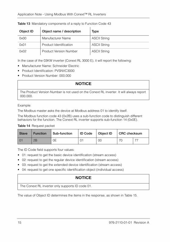
In the case of the 03KW inverter (Conext RL 3000 E), it will report the following:
• Manufacturer Name: Schneider Electric
• Product Identification: PVSNVC3000
• Product Version Number: 000.000
Example:
The Modbus master asks the device at Modbus address 01 to identify itself.
The Modbus function code 43 (0x2B) uses a sub-function code to distinguish different behaviors for the function. The Conext RL inverter supports sub-function 14 (0x0E).
The ID Code field supports four values:
• 01: request to get the basic device identification (stream access)
• 02: request to get the regular device identification (stream access)
• 03: request to get the extended device identification (stream access)
• 04: request to get one specific identification object (individual access)
The value of Object ID determines the items in the response, as shown in Table 15.
Table 13 Mandatory components of a reply to Function Code 43
Object ID Object name / description Type
0x00 Manufacturer Name ASCII String
0x01 Product Identification ASCII String
0x02 Product Version Number ASCII String
NOTICE
The Product Version Number is not used on the Conext RL inverter. It will always report 000.000.
Table 14 Request packet
Slave Function Sub-function ID Code Object ID CRC checksum
01 2B 0E 01 00 70 77
NOTICE
The Conext RL inverter only supports ID code 01.
15 976-2110-01-01 Revision A
Application Note - Using Modbus With Conext™ RL Inverters
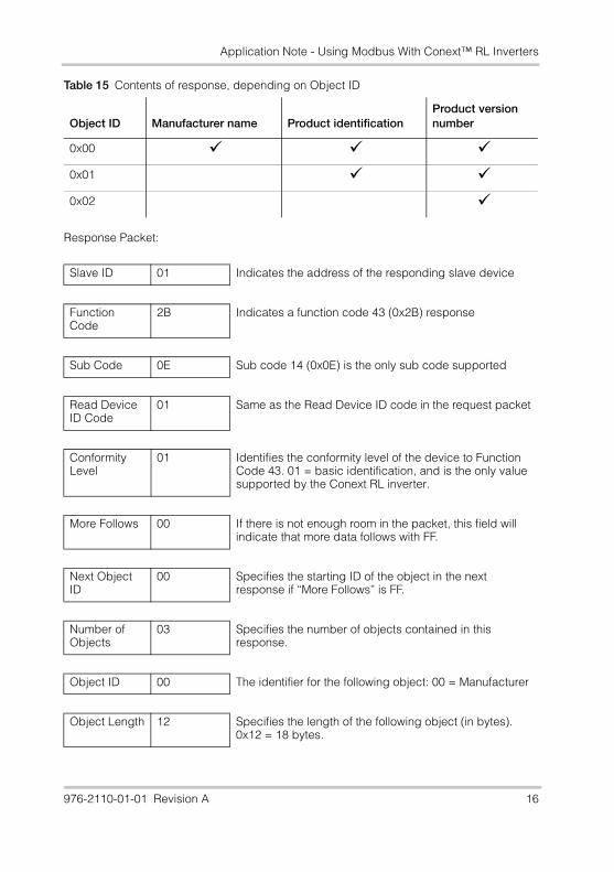
Response Packet:
Table 15 Contents of response, depending on Object ID
Object ID Manufacturer name Product identificationProduct version number
0x00
0x01
0x02
Slave ID 01 Indicates the address of the responding slave device
Function Code
2B Indicates a function code 43 (0x2B) response
Sub Code 0E Sub code 14 (0x0E) is the only sub code supported
Read Device ID Code
01 Same as the Read Device ID code in the request packet
Conformity Level
01 Identifies the conformity level of the device to Function Code 43. 01 = basic identification, and is the only value supported by the Conext RL inverter.
More Follows 00 If there is not enough room in the packet, this field will indicate that more data follows with FF.
Next Object ID
00 Specifies the starting ID of the object in the next response if “More Follows” is FF.
Number of Objects
03 Specifies the number of objects contained in this response.
Object ID 00 The identifier for the following object: 00 = Manufacturer
Object Length 12 Specifies the length of the following object (in bytes). 0x12 = 18 bytes.
976-2110-01-01 Revision A 16
Application Note - Using Modbus With Conext™ RL Inverters
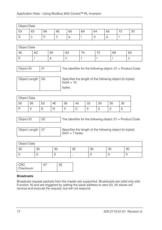
Broadcasts
Broadcast request packets from the master are supported. Broadcasts are valid only with Function 16 and are triggered by setting the slave address to zero (0). All slaves will receive and execute the request, but will not respond.
Object Data
53 63 68 6E 65 69 64 65 72 20
S c h n e i d e r
Object Data
45 6C 65 63 74 72 69 63
E l e c t r i c
Object ID 01 The identifier for the following object: 01 = Product Code
Object Length 0A Specifies the length of the following object (in bytes). 0x0A = 10
bytes.
Object Data
50 56 53 4E 56 43 33 30 30 30
P V S N V C 3 0 0 0
Object ID 02 The identifier for the following object: 01 = Product Code
Object Length 07 Specifies the length of the following object (in bytes). 0x07 = 7 bytes.
Object Data
30 30 30 2E 30 30 30
0 0 0 . 0 0 0
CRC Checksum
A7 2E
17 976-2110-01-01 Revision A
Application Note - Using Modbus With Conext™ RL Inverters
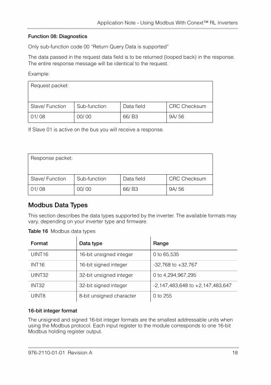
Function 08: Diagnostics
Only sub-function code 00 “Return Query Data is supported”
The data passed in the request data field is to be returned (looped back) in the response. The entire response message will be identical to the request.
Example:
If Slave 01 is active on the bus you will receive a response.
Modbus Data Types
This section describes the data types supported by the inverter. The available formats may vary, depending on your inverter type and firmware.
16-bit integer format
The unsigned and signed 16-bit integer formats are the smallest addressable units when using the Modbus protocol. Each input register to the module corresponds to one 16-bit Modbus holding register output.
Request packet:
Slave/ Function Sub-function Data field CRC Checksum
01/ 08 00/ 00 66/ B3 9A/ 56
Response packet:
Slave/ Function Sub-function Data field CRC Checksum
01/ 08 00/ 00 66/ B3 9A/ 56
Table 16 Modbus data types
Format Data type Range
UINT16 16-bit unsigned integer 0 to 65,535
INT16 16-bit signed integer -32,768 to +32,767
UINT32 32-bit unsigned integer 0 to 4,294,967,295
INT32 32-bit signed integer -2,147,483,648 to +2,147,483,647
UINT8 8-bit unsigned character 0 to 255
976-2110-01-01 Revision A 18
Application Note - Using Modbus With Conext™ RL Inverters
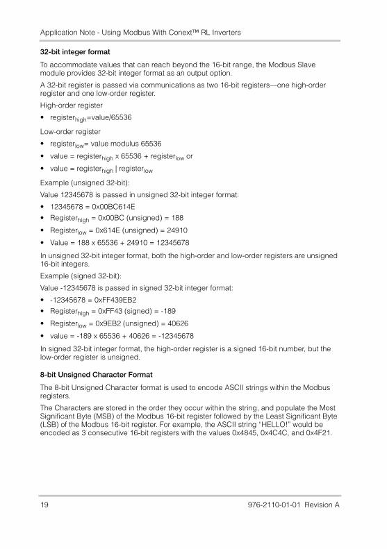
32-bit integer format
To accommodate values that can reach beyond the 16-bit range, the Modbus Slave module provides 32-bit integer format as an output option.
A 32-bit register is passed via communications as two 16-bit registers—one high-order register and one low-order register.
High-order register
• registerhigh=value/65536
Low-order register
• registerlow= value modulus 65536
• value = registerhigh x 65536 + registerlow or
• value = registerhigh | registerlow
Example (unsigned 32-bit):
Value 12345678 is passed in unsigned 32-bit integer format:
• 12345678 = 0x00BC614E
• Registerhigh = 0x00BC (unsigned) = 188
• Registerlow = 0x614E (unsigned) = 24910
• Value = 188 x 65536 + 24910 = 12345678
In unsigned 32-bit integer format, both the high-order and low-order registers are unsigned 16-bit integers.
Example (signed 32-bit):
Value -12345678 is passed in signed 32-bit integer format:
• -12345678 = 0xFF439EB2
• Registerhigh = 0xFF43 (signed) = -189
• Registerlow = 0x9EB2 (unsigned) = 40626
• value = -189 x 65536 + 40626 = -12345678
In signed 32-bit integer format, the high-order register is a signed 16-bit number, but the low-order register is unsigned.
8-bit Unsigned Character Format
The 8-bit Unsigned Character format is used to encode ASCII strings within the Modbus registers.
The Characters are stored in the order they occur within the string, and populate the Most Significant Byte (MSB) of the Modbus 16-bit register followed by the Least Significant Byte (LSB) of the Modbus 16-bit register. For example, the ASCII string “HELLO!” would be encoded as 3 consecutive 16-bit registers with the values 0x4845, 0x4C4C, and 0x4F21.
19 976-2110-01-01 Revision A
Application Note - Using Modbus With Conext™ RL Inverters
Modbus Error Responses
If the inverter receives an unsupported Modbus request, it returns an exception response informing the Modbus master of the nature of the error.
The Modbus Error Response message has two fields that differentiate it from a normal response: Function Code Field, and Data Field.
Function Code Field
In a normal response, the inverter echoes the function code of the original request in the function code field of the response. All the function codes have a most-significant bit (MSB) of 0 (their values are all below 0x80).
In an exception response, the inverter sets the MSB of the function code to 1. This makes the function code value in an exception response exactly 0x80 higher than the value for a normal response. For example, a normal response of 0x03 (Read Holding Registers), becomes 0x83 (Unable to Read Holding Registers).
Data Field
In an error response, the inverter uses the data field of the response packet to return an error code to the Modbus Master. Four error codes are supported, as shown in Table 18.
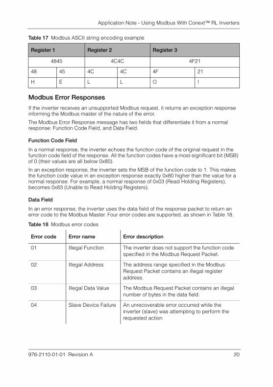
Table 17 Modbus ASCII string encoding example
Register 1 Register 2 Register 3
4845 4C4C 4F21
48 45 4C 4C 4F 21
H E L L O !
Table 18 Modbus error codes
Error code Error name Error description
01 Illegal Function The inverter does not support the function code specified in the Modbus Request Packet.
02 Illegal Address The address range specified in the Modbus Request Packet contains an illegal register address.
03 Illegal Data Value The Modbus Request Packet contains an illegal number of bytes in the data field.
04 Slave Device Failure An unrecoverable error occurred while the inverter (slave) was attempting to perform the requested action
976-2110-01-01 Revision A 20
Application Note - Using Modbus With Conext™ RL Inverters
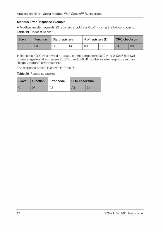
Modbus Error Response Example
A Modbus master requests 22 registers at address 0x0014 using the following query:
In this case, 0x0014 is a valid address, but the range from 0x0014 to 0x001F has two missing registers at addresses 0x001E, and 0x001F, so the inverter responds with an “Illegal Address” error response.
The response packet is shown in Table 20.
Table 19 Request packet
Slave Function Start registers # of registers (1) CRC checksum
01 03 00 14 00 16 84 00
Table 20 Response packet
Slave Function Error code CRC checksum
01 03 02 A1 31
21 976-2110-01-01 Revision A
Application Note - Using Modbus With Conext™ RL Inverters
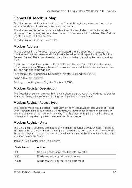
Conext RL Modbus MapThe Modbus map defines the location of the Conext RL registers, which can be used to retrieve the status information or to control the inverter.
The Modbus map is defined as a data table, the columns of which define the register attributes. (The following sections describe each of the columns in the table.) The Modbus registers are defined one per row.
The Modbus map is shown in Table 23.
Modbus Address
The addresses in the Modbus map are zero-based and are specified in hexadecimal notation, so that they correspond directly with the address field specified in the Modbus Request Packet. This makes it easier to troubleshoot when capturing the data “over-the-wire”.
If you need to enter these values into the data definition file of a Modbus Master device, which is expecting a “Register Number”, you need to convert the address to decimal (base 10), and add one to the address.
For example, the “Operational Mode State” register is at address 0x1700.
0x0x1700 = 5888 decimal.
Adding one to this gives a Register Number of 5889.
Modbus Register Description
The Description column provides brief details about the purpose of the Modbus register, for example, “Energy Since Commissioning”, or “Operational Mode State”.
Modbus Register Access type
The Access types may be either “Read Only” or “R/W” (Read/Write). The values of “Read Only” registers cannot be changed via Modbus, so they cannot be used to configure or alter the behavior of the inverter in any way. The “Read/Write” registers may be altered at run-time and may directly affect the operation of the inverter.
Modbus Register Units
The Units column specifies two pieces of information separated by a / symbol. The first is the units of the value contained in the register, for example, kWh, V, A, Vrms. The second is the scaling factor to convert the raw binary value contained within the register to the units specified before the / symbol.
Table 21 Scale factor in the Units column
Scale factor Action
X1 No divide necessary: result equals raw value
X10 Divide raw value by 10 to yield the result
X100 Divide raw value by 100 to yield the result
976-2110-01-01 Revision A 22
Application Note - Using Modbus With Conext™ RL Inverters
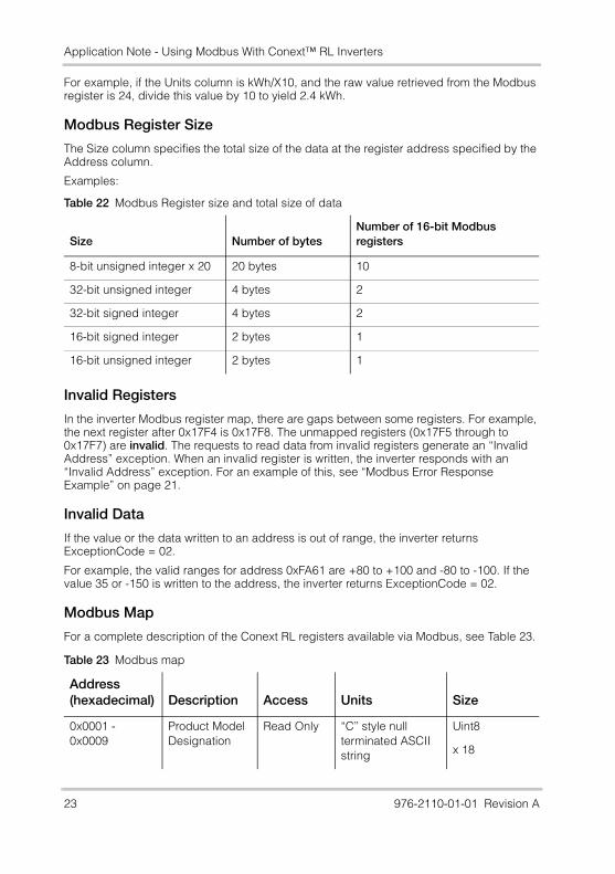
For example, if the Units column is kWh/X10, and the raw value retrieved from the Modbus register is 24, divide this value by 10 to yield 2.4 kWh.
Modbus Register Size
The Size column specifies the total size of the data at the register address specified by the Address column.
Examples:
Invalid Registers
In the inverter Modbus register map, there are gaps between some registers. For example, the next register after 0x17F4 is 0x17F8. The unmapped registers (0x17F5 through to 0x17F7) are invalid. The requests to read data from invalid registers generate an “Invalid Address” exception. When an invalid register is written, the inverter responds with an “Invalid Address” exception. For an example of this, see “Modbus Error Response Example” on page 21.
Invalid Data
If the value or the data written to an address is out of range, the inverter returns ExceptionCode = 02.
For example, the valid ranges for address 0xFA61 are +80 to +100 and -80 to -100. If the value 35 or -150 is written to the address, the inverter returns ExceptionCode = 02.
Modbus Map
For a complete description of the Conext RL registers available via Modbus, see Table 23.
Table 22 Modbus Register size and total size of data
Size Number of bytesNumber of 16-bit Modbus registers
8-bit unsigned integer x 20 20 bytes 10
32-bit unsigned integer 4 bytes 2
32-bit signed integer 4 bytes 2
16-bit signed integer 2 bytes 1
16-bit unsigned integer 2 bytes 1
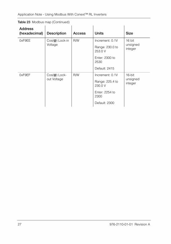
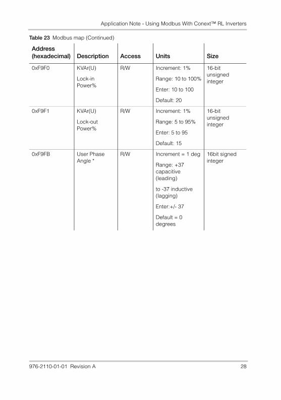
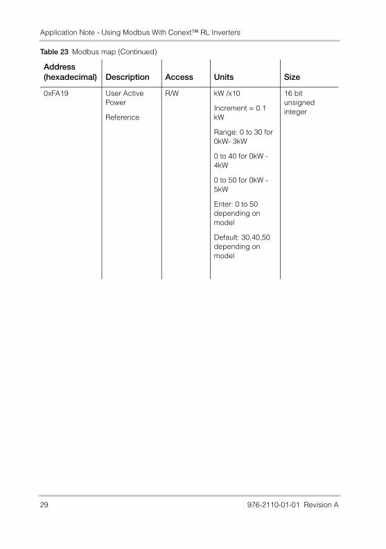
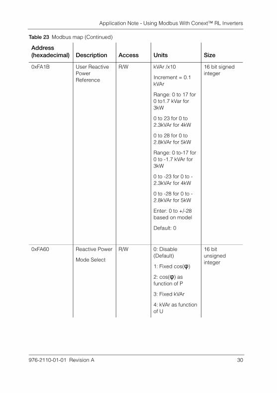
Table 23 Modbus map
Address(hexadecimal) Description Access Units Size
0x0001 - 0x0009
Product Model Designation
Read Only “C” style null terminated ASCII string
Uint8
x 18
23 976-2110-01-01 Revision A
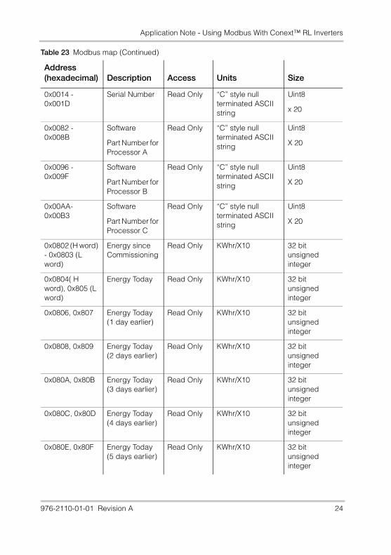
Application Note - Using Modbus With Conext™ RL Inverters
0x0014 - 0x001D
Serial Number Read Only “C” style null terminated ASCII string
Uint8
x 20
0x0082 - 0x008B
Software
Part Number for Processor A
Read Only “C” style null terminated ASCII string
Uint8
X 20
0x0096 - 0x009F
Software
Part Number for Processor B
Read Only “C” style null terminated ASCII string
Uint8
X 20
0x00AA- 0x00B3
Software
Part Number for Processor C
Read Only “C” style null terminated ASCII string
Uint8
X 20
0x0802 (H word) - 0x0803 (L word)
Energy since Commissioning
Read Only KWhr/X10 32 bit unsigned integer
0x0804( H word), 0x805 (L word)
Energy Today Read Only KWhr/X10 32 bit unsigned integer
0x0806, 0x807 Energy Today (1 day earlier)
Read Only KWhr/X10 32 bit unsigned integer
0x0808, 0x809 Energy Today (2 days earlier)
Read Only KWhr/X10 32 bit unsigned integer
0x080A, 0x80B Energy Today (3 days earlier)
Read Only KWhr/X10 32 bit unsigned integer
0x080C, 0x80D Energy Today (4 days earlier)
Read Only KWhr/X10 32 bit unsigned integer
0x080E, 0x80F Energy Today (5 days earlier)
Read Only KWhr/X10 32 bit unsigned integer
Table 23 Modbus map (Continued)
Address(hexadecimal) Description Access Units Size
976-2110-01-01 Revision A 24
Application Note - Using Modbus With Conext™ RL Inverters
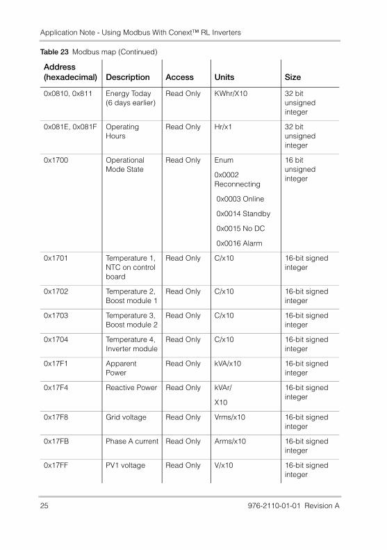
0x0810, 0x811 Energy Today (6 days earlier)
Read Only KWhr/X10 32 bit unsigned integer
0x081E, 0x081F Operating Hours
Read Only Hr/x1 32 bit unsigned integer
0x1700 Operational Mode State
Read Only Enum
0x0002 Reconnecting
0x0003 Online
0x0014 Standby
0x0015 No DC
0x0016 Alarm
16 bit unsigned integer
0x1701 Temperature 1, NTC on control board
Read Only C/x10 16-bit signed integer
0x1702 Temperature 2, Boost module 1
Read Only C/x10 16-bit signed integer
0x1703 Temperature 3, Boost module 2
Read Only C/x10 16-bit signed integer
0x1704 Temperature 4, Inverter module
Read Only C/x10 16-bit signed integer
0x17F1 Apparent Power
Read Only kVA/x10 16-bit signed integer
0x17F4 Reactive Power Read Only kVAr/
X10
16-bit signed integer
0x17F8 Grid voltage Read Only Vrms/x10 16-bit signed integer
0x17FB Phase A current Read Only Arms/x10 16-bit signed integer
0x17FF PV1 voltage Read Only V/x10 16-bit signed integer
Table 23 Modbus map (Continued)
Address(hexadecimal) Description Access Units Size
25 976-2110-01-01 Revision A
Application Note - Using Modbus With Conext™ RL Inverters
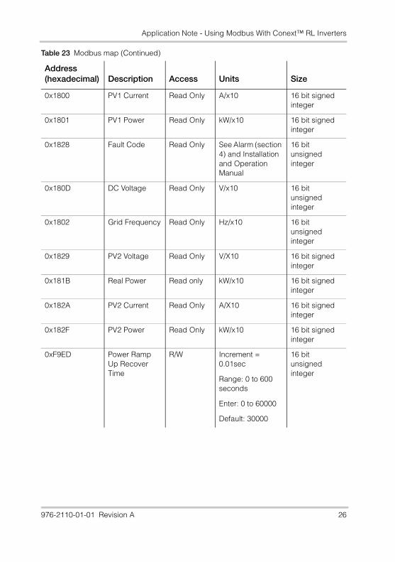
0x1800 PV1 Current Read Only A/x10 16 bit signed integer
0x1801 PV1 Power Read Only kW/x10 16 bit signed integer
0x1828 Fault Code Read Only See Alarm (section 4) and Installation and Operation Manual
16 bit unsigned integer
0x180D DC Voltage Read Only V/x10 16 bit unsigned integer
0x1802 Grid Frequency Read Only Hz/x10 16 bit unsigned integer
0x1829 PV2 Voltage Read Only V/X10 16 bit signed integer
0x181B Real Power Read only kW/x10 16 bit signed integer
0x182A PV2 Current Read Only A/X10 16 bit signed integer
0x182F PV2 Power Read Only kW/x10 16 bit signed integer
0xF9ED Power Ramp Up Recover Time
R/W Increment = 0.01sec
Range: 0 to 600 seconds
Enter: 0 to 60000
Default: 30000
16 bit unsigned integer
Table 23 Modbus map (Continued)
Address(hexadecimal) Description Access Units Size
976-2110-01-01 Revision A 26
Application Note - Using Modbus With Conext™ RL Inverters
0xF9EE Cos(φ) Lock-in Voltage
R/W Increment: 0.1V
Range: 230.0 to 253.0 V
Enter: 2300 to 2530
Default: 2415
16 bit unsigned integer
0xF9EF Cos(φ) Lock-out Voltage
R/W Increment: 0.1V
Range: 225.4 to 230.0 V
Enter: 2254 to 2300
Default: 2300
16-bit unsigned integer
Table 23 Modbus map (Continued)
Address(hexadecimal) Description Access Units Size
27 976-2110-01-01 Revision A
Application Note - Using Modbus With Conext™ RL Inverters
0xF9F0 KVAr(U)
Lock-in Power%
R/W Increment: 1%
Range: 10 to 100%
Enter: 10 to 100
Default: 20
16-bit unsigned integer
0xF9F1 KVAr(U)
Lock-out Power%
R/W Increment: 1%
Range: 5 to 95%
Enter: 5 to 95
Default: 15
16-bit unsigned integer
0xF9FB User Phase Angle *
R/W Increment = 1 deg
Range: +37 capacitive (leading)
to -37 inductive (lagging)
Enter:+/- 37
Default = 0 degrees
16bit signed integer
Table 23 Modbus map (Continued)
Address(hexadecimal) Description Access Units Size
976-2110-01-01 Revision A 28
Application Note - Using Modbus With Conext™ RL Inverters
0xFA19 User Active Power
Reference
R/W kW /x10
Increment = 0.1 kW
Range: 0 to 30 for 0kW- 3kW
0 to 40 for 0kW - 4kW
0 to 50 for 0kW - 5kW
Enter: 0 to 50 depending on model
Default: 30,40,50 depending on model
16 bit unsigned integer
Table 23 Modbus map (Continued)
Address(hexadecimal) Description Access Units Size
29 976-2110-01-01 Revision A
Application Note - Using Modbus With Conext™ RL Inverters
0xFA1B User Reactive Power Reference
R/W kVAr /x10
Increment = 0.1 kVAr
Range: 0 to 17 for 0 to1.7 kVar for 3kW
0 to 23 for 0 to 2.3kVAr for 4kW
0 to 28 for 0 to 2.8kVAr for 5kW
Range: 0 to-17 for 0 to -1.7 kVAr for 3kW
0 to -23 for 0 to -2.3kVAr for 4kW
0 to -28 for 0 to -2.8kVAr for 5kW
Enter: 0 to +/-28 based on model
Default: 0
16 bit signed integer
0xFA60 Reactive Power
Mode Select
R/W 0: Disable (Default)
1: Fixed cos(φ)
2: cos(φ) as function of P
3: Fixed kVAr
4: kVAr as function of U
16 bit unsigned integer
Table 23 Modbus map (Continued)
Address(hexadecimal) Description Access Units Size
976-2110-01-01 Revision A 30
Application Note - Using Modbus With Conext™ RL Inverters
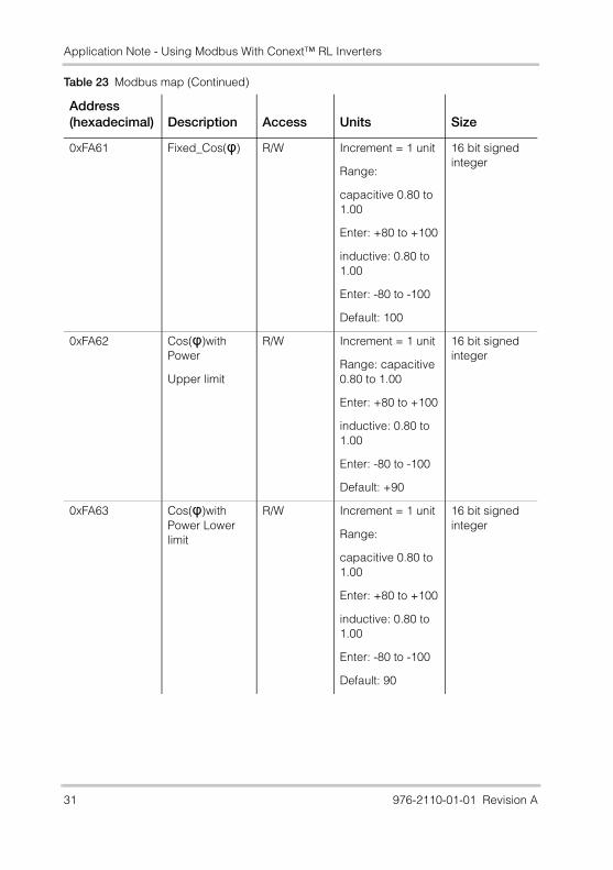
0xFA61 Fixed_Cos(φ) R/W Increment = 1 unit
Range:
capacitive 0.80 to 1.00
Enter: +80 to +100
inductive: 0.80 to 1.00
Enter: -80 to -100
Default: 100
16 bit signed integer
0xFA62 Cos(φ)with Power
Upper limit
R/W Increment = 1 unit
Range: capacitive 0.80 to 1.00
Enter: +80 to +100
inductive: 0.80 to 1.00
Enter: -80 to -100
Default: +90
16 bit signed integer
0xFA63 Cos(φ)with Power Lower limit
R/W Increment = 1 unit
Range:
capacitive 0.80 to 1.00
Enter: +80 to +100
inductive: 0.80 to 1.00
Enter: -80 to -100
Default: 90
16 bit signed integer
Table 23 Modbus map (Continued)
Address(hexadecimal) Description Access Units Size
31 976-2110-01-01 Revision A
Application Note - Using Modbus With Conext™ RL Inverters
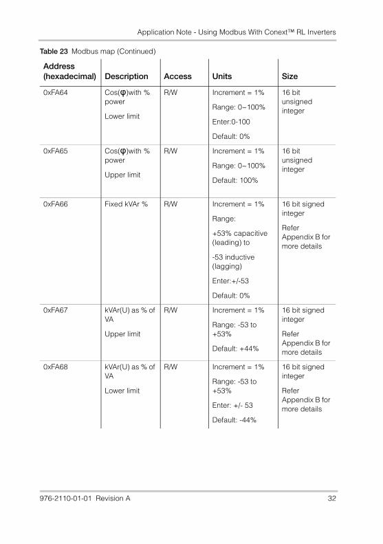
0xFA64 Cos(φ)with % power
Lower limit
R/W Increment = 1%
Range: 0~100%
Enter:0-100
Default: 0%
16 bit unsigned integer
0xFA65 Cos(φ)with % power
Upper limit
R/W Increment = 1%
Range: 0~100%
Default: 100%
16 bit unsigned integer
0xFA66 Fixed kVAr % R/W Increment = 1%
Range:
+53% capacitive (leading) to
-53 inductive (lagging)
Enter:+/-53
Default: 0%
16 bit signed integer
Refer Appendix B for more details
0xFA67 kVAr(U) as % of VA
Upper limit
R/W Increment = 1%
Range: -53 to +53%
Default: +44%
16 bit signed integer
Refer Appendix B for more details
0xFA68 kVAr(U) as % of VA
Lower limit
R/W Increment = 1%
Range: -53 to +53%
Enter: +/- 53
Default: -44%
16 bit signed integer
Refer Appendix B for more details
Table 23 Modbus map (Continued)
Address(hexadecimal) Description Access Units Size
976-2110-01-01 Revision A 32
Application Note - Using Modbus With Conext™ RL Inverters
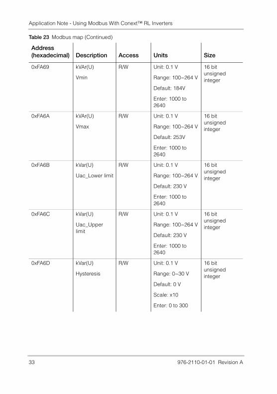
0xFA69 kVAr(U)
Vmin
R/W Unit: 0.1 V
Range: 100~264 V
Default: 184V
Enter: 1000 to 2640
16 bit unsigned integer
0xFA6A kVAr(U)
Vmax
R/W Unit: 0.1 V
Range: 100~264 V
Default: 253V
Enter: 1000 to 2640
16 bit unsigned integer
0xFA6B kVar(U)
Uac_Lower limit
R/W Unit: 0.1 V
Range: 100~264 V
Default: 230 V
Enter: 1000 to 2640
16 bit unsigned integer
0xFA6C kVar(U)
Uac_Upper limit
R/W Unit: 0.1 V
Range: 100~264 V
Default: 230 V
Enter: 1000 to 2640
16 bit unsigned integer
0xFA6D kVar(U)
Hysteresis
R/W Unit: 0.1 V
Range: 0~30 V
Default: 0 V
Scale: x10
Enter: 0 to 300
16 bit unsigned integer
Table 23 Modbus map (Continued)
Address(hexadecimal) Description Access Units Size
33 976-2110-01-01 Revision A
Application Note - Using Modbus With Conext™ RL Inverters
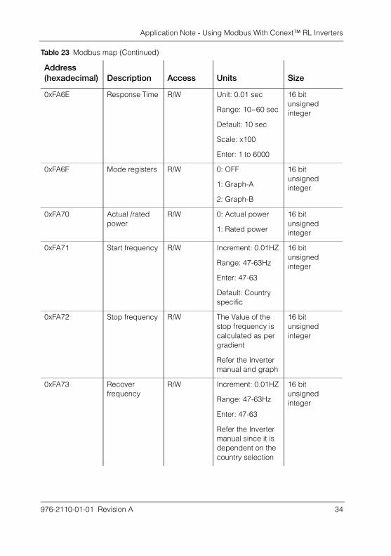
0xFA6E Response Time R/W Unit: 0.01 sec
Range: 10~60 sec
Default: 10 sec
Scale: x100
Enter: 1 to 6000
16 bit unsigned integer
0xFA6F Mode registers R/W 0: OFF
1: Graph-A
2: Graph-B
16 bit unsigned integer
0xFA70 Actual /rated power
R/W 0: Actual power
1: Rated power
16 bit unsigned integer
0xFA71 Start frequency R/W Increment: 0.01HZ
Range: 47-63Hz
Enter: 47-63
Default: Country specific
16 bit unsigned integer
0xFA72 Stop frequency R/W The Value of the stop frequency is calculated as per gradient
Refer the Inverter manual and graph
16 bit unsigned integer
0xFA73 Recover frequency
R/W Increment: 0.01HZ
Range: 47-63Hz
Enter: 47-63
Refer the Inverter manual since it is dependent on the country selection
16 bit unsigned integer
Table 23 Modbus map (Continued)
Address(hexadecimal) Description Access Units Size
976-2110-01-01 Revision A 34
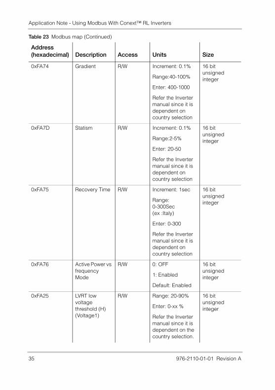
Application Note - Using Modbus With Conext™ RL Inverters
0xFA74 Gradient R/W Increment: 0.1%
Range:40-100%
Enter: 400-1000
Refer the Inverter manual since it is dependent on country selection
16 bit unsigned integer
0xFA7D Statism R/W Increment: 0.1%
Range:2-5%
Enter: 20-50
Refer the Inverter manual since it is dependent on country selection
16 bit unsigned integer
0xFA75 Recovery Time R/W Increment: 1sec
Range:0-300Sec (ex :Italy)
Enter: 0-300
Refer the Inverter manual since it is dependent on country selection
16 bit unsigned integer
0xFA76 Active Power vs frequency Mode
R/W 0: OFF
1: Enabled
Default: Enabled
16 bit unsigned integer
0xFA25 LVRT low voltage threshold (H) (Voltage1)
R/W Range: 20-90%
Enter: 0-xx %
Refer the Inverter manual since it is dependent on the country selection.
16 bit unsigned integer
Table 23 Modbus map (Continued)
Address(hexadecimal) Description Access Units Size
35 976-2110-01-01 Revision A
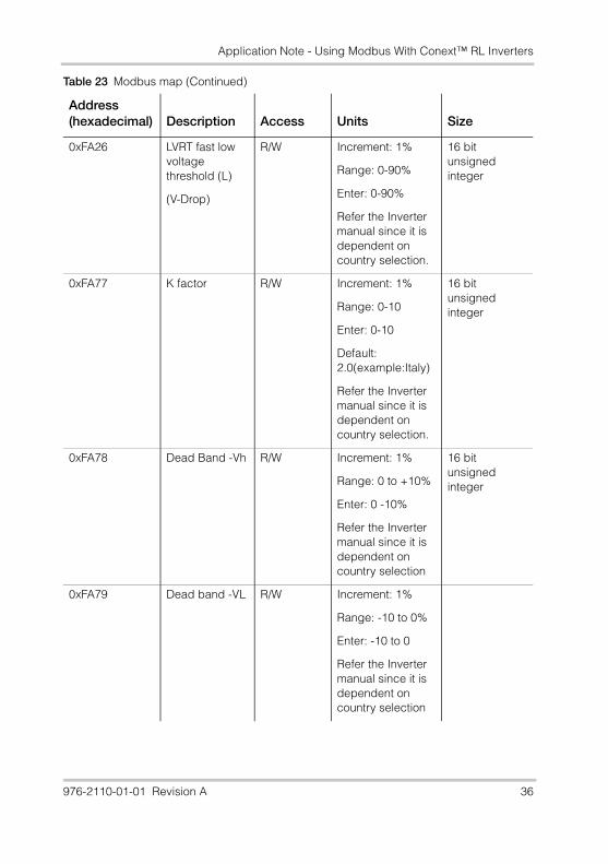
Application Note - Using Modbus With Conext™ RL Inverters
0xFA26 LVRT fast low voltage threshold (L)
(V-Drop)
R/W Increment: 1%
Range: 0-90%
Enter: 0-90%
Refer the Inverter manual since it is dependent on country selection.
16 bit unsigned integer
0xFA77 K factor R/W Increment: 1%
Range: 0-10
Enter: 0-10
Default: 2.0(example:Italy)
Refer the Inverter manual since it is dependent on country selection.
16 bit unsigned integer
0xFA78 Dead Band -Vh R/W Increment: 1%
Range: 0 to +10%
Enter: 0 -10%
Refer the Inverter manual since it is dependent on country selection
16 bit unsigned integer
0xFA79 Dead band -VL R/W Increment: 1%
Range: -10 to 0%
Enter: -10 to 0
Refer the Inverter manual since it is dependent on country selection
Table 23 Modbus map (Continued)
Address(hexadecimal) Description Access Units Size
976-2110-01-01 Revision A 36
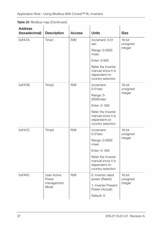
Application Note - Using Modbus With Conext™ RL Inverters
0xFA7A Time1 R/W Increment: 0.01 sec
Range: 0-5000 msec
Enter: 0-500
Refer the Inverter manual since it is dependent on country selection
16 bit unsigned integer
0xFA7B Time2 R/W Increment: 0.01sec
Range: 0-5000msec
Enter: 0- 500
Refer the Inverter manual since it is dependent on country selection.
16 bit unsigned integer
0xFA7C Time3 R/W Increment: 0.01sec
Range: 0-5000 msec
Enter: 0- 500
Refer the Inverter manual since it is dependent on country selection.
16 bit unsigned integer
0xFAF0 User Active Power management Mode
R/W 0: Inverter rated power (Rated)
1: Inverter Present Power (Actual)
Default: 0
16 bit unsigned integer
Table 23 Modbus map (Continued)
Address(hexadecimal) Description Access Units Size
37 976-2110-01-01 Revision A
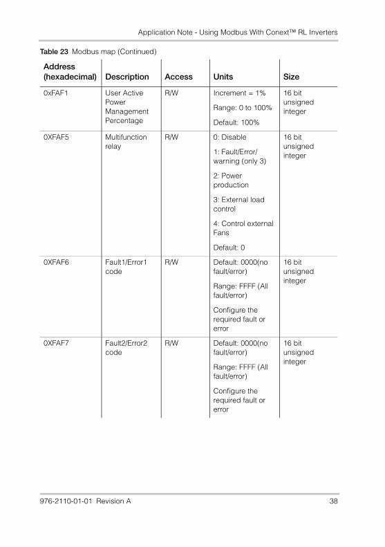
Application Note - Using Modbus With Conext™ RL Inverters
0xFAF1 User Active Power Management Percentage
R/W Increment = 1%
Range: 0 to 100%
Default: 100%
16 bit unsigned integer
0XFAF5 Multifunction relay
R/W 0: Disable
1: Fault/Error/warning (only 3)
2: Power production
3: External load control
4: Control external Fans
Default: 0
16 bit unsigned integer
0XFAF6 Fault1/Error1 code
R/W Default: 0000(no fault/error)
Range: FFFF (All fault/error)
Configure the required fault or error
16 bit unsigned integer
0XFAF7 Fault2/Error2 code
R/W Default: 0000(no fault/error)
Range: FFFF (All fault/error)
Configure the required fault or error
16 bit unsigned integer
Table 23 Modbus map (Continued)
Address(hexadecimal) Description Access Units Size
976-2110-01-01 Revision A 38
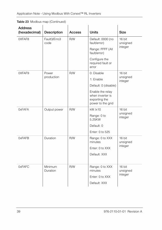
Application Note - Using Modbus With Conext™ RL Inverters
0XFAF8 Fault3/Erro3 code
R/W Default: 0000 (no fault/error)
Range: FFFF (All fault/error)
Configure the required fault or error
16 bit unsigned integer
0XFAF9 Power production
R/W 0: Disable
1: Enable
Default: 0 (disable)
Enable the relay when inverter is exporting the power to the grid
16 bit unsigned integer
0xFAFA Output power R/W kW /x10
Range: 0 to 5.25KW
Default: 0
Enter: 0 to 525
16 bit unsigned integer
0xFAFB Duration R/W Range: 0 to XXX minutes
Enter: 0 to XXX
Default: XXX
16 bit unsigned integer
0xFAFC Minimum Duration
R/W Range: 0 to XXX minutes
Enter: 0 to XXX
Default: XXX
16 bit unsigned integer
Table 23 Modbus map (Continued)
Address(hexadecimal) Description Access Units Size
39 976-2110-01-01 Revision A
Application Note - Using Modbus With Conext™ RL Inverters
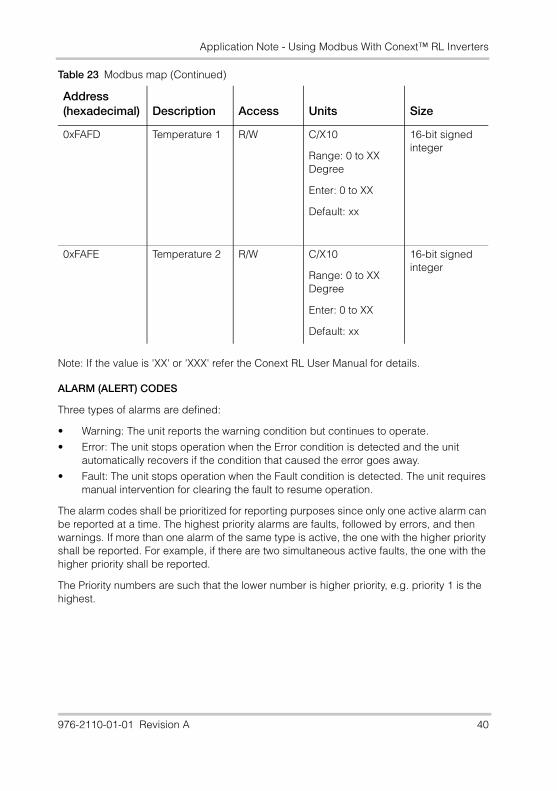
Note: If the value is 'XX' or 'XXX' refer the Conext RL User Manual for details.
ALARM (ALERT) CODES
Three types of alarms are defined:
• Warning: The unit reports the warning condition but continues to operate.
• Error: The unit stops operation when the Error condition is detected and the unit automatically recovers if the condition that caused the error goes away.
• Fault: The unit stops operation when the Fault condition is detected. The unit requires manual intervention for clearing the fault to resume operation.
The alarm codes shall be prioritized for reporting purposes since only one active alarm can be reported at a time. The highest priority alarms are faults, followed by errors, and then warnings. If more than one alarm of the same type is active, the one with the higher priority shall be reported. For example, if there are two simultaneous active faults, the one with the higher priority shall be reported.
The Priority numbers are such that the lower number is higher priority, e.g. priority 1 is the highest.
0xFAFD Temperature 1 R/W C/X10
Range: 0 to XX Degree
Enter: 0 to XX
Default: xx
16-bit signed integer
0xFAFE Temperature 2 R/W C/X10
Range: 0 to XX Degree
Enter: 0 to XX
Default: xx
16-bit signed integer
Table 23 Modbus map (Continued)
Address(hexadecimal) Description Access Units Size
976-2110-01-01 Revision A 40
Application Note - Using Modbus With Conext™ RL Inverters
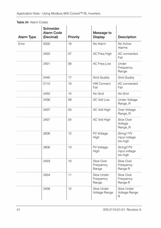
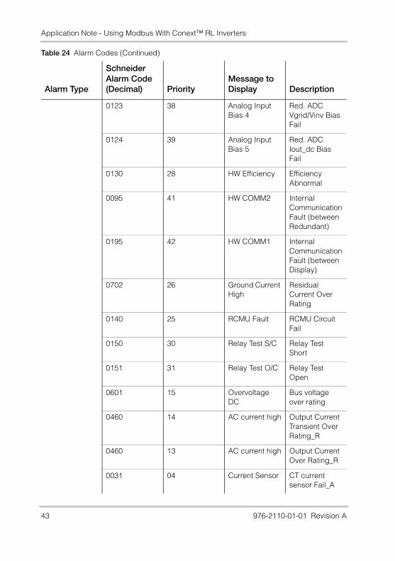
Table 24 Alarm Codes
Alarm Type
Schneider Alarm Code(Decimal) Priority
Message to Display Description
Error 0000 18 No Alarm No Active Alarms
2402 07 AC Freq High AC connected Fail
2401 08 AC Freq Low Under Frequency Range
2440 17 Grid Quality Grid Quality
2110 16 HW Connect Fail
AC connected Fail
2450 15 No Grid No Grid
2406 09 AC Volt Low Under Voltage Range_R
2407 03 AC Volt High Over Voltage Range_R
2407 04 AC Volt High Slow Over Voltage Range_R
2606 12 PV Voltage High
String1 PV input voltage too high
2606 13 PV Voltage High
String2 PV input voltage too high
2403 10 Slow Over Frequency Range
Slow Over Frequency Range R
2404 11 Slow Under Frequency Range
Slow Over Frequency Range R
2408 12 Slow Under Voltage Range
Slow Under Voltage Range R
41 976-2110-01-01 Revision A
Application Note - Using Modbus With Conext™ RL Inverters
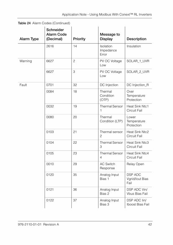
2616 14 Isolation Impedance Error
Insulation
Warning 6627 2 PV OC Voltage Low
SOLAR_1_UVR
6627 3 PV OC Voltage Low
SOLAR_2_UVR
Fault 0701 32 DC Injection DC Injection_R
0084 18 Thermal Condition (OTP)
Over Temperature Protection
0032 19 Thermal Sensor 1
Heat Sink Ntc1 Circuit Fail
0080 20 Thermal Condition (LTP)
Lower Temperature Protection
0103 21 Thermal sensor 2
Heat Sink Ntc2 Circuit Fail
0104 22 Thermal Sensor 3
Heat Sink Ntc3 Circuit Fail
0105 23 Thermal Sensor 4
Heat Sink Ntc4 Circuit Fail
0010 29 AC Switch Response
Relay Open
0120 35 Analog Input Bias 1
DSP ADC Vgrid/Iout Bias Fail
0121 36 Analog Input Bias 2
DSP ADC Vin/Vbus Bias Fail
0122 37 Analog Input Bias 3
DSP ADC Iin/Iboost Bias Fail
Table 24 Alarm Codes (Continued)
Alarm Type
Schneider Alarm Code(Decimal) Priority
Message to Display Description
976-2110-01-01 Revision A 42
Application Note - Using Modbus With Conext™ RL Inverters
0123 38 Analog Input Bias 4
Red. ADC Vgrid/Vinv Bias Fail
0124 39 Analog Input Bias 5
Red. ADC Iout_dc Bias Fail
0130 28 HW Efficiency Efficiency Abnormal
0095 41 HW COMM2 Internal Communication Fault (between Redundant)
0195 42 HW COMM1 Internal Communication Fault (between Display)
0702 26 Ground Current High
Residual Current Over Rating
0140 25 RCMU Fault RCMU Circuit Fail
0150 30 Relay Test S/C Relay Test Short
0151 31 Relay Test O/C Relay Test Open
0601 15 Overvoltage DC
Bus voltage over rating
0460 14 AC current high Output Current Transient Over Rating_R
0460 13 AC current high Output Current Over Rating_R
0031 04 Current Sensor CT current sensor Fail_A
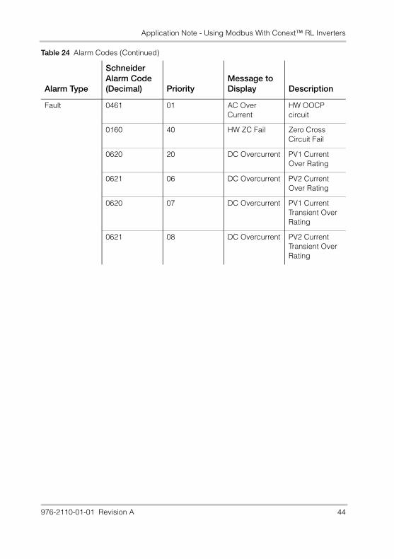
Table 24 Alarm Codes (Continued)
Alarm Type
Schneider Alarm Code(Decimal) Priority
Message to Display Description
43 976-2110-01-01 Revision A
Application Note - Using Modbus With Conext™ RL Inverters
Fault 0461 01 AC Over Current
HW OOCP circuit
0160 40 HW ZC Fail Zero Cross Circuit Fail
0620 20 DC Overcurrent PV1 Current Over Rating
0621 06 DC Overcurrent PV2 Current Over Rating
0620 07 DC Overcurrent PV1 Current Transient Over Rating
0621 08 DC Overcurrent PV2 Current Transient Over Rating
Table 24 Alarm Codes (Continued)
Alarm Type
Schneider Alarm Code(Decimal) Priority
Message to Display Description
976-2110-01-01 Revision A 44
Application Note - Using Modbus With Conext™ RL Inverters
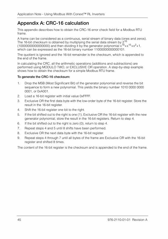
Appendix A: CRC-16 calculationThis appendix describes how to obtain the CRC-16 error check field for a Modbus RTU frame.
A frame can be considered as a continuous, serial stream of binary data (ones and zeros). The 16-bit checksum is obtained by multiplying the serial data stream by 216 (10000000000000000) and then dividing it by the generator polynomial x16+x15+x2+1, which can be expressed as the 16-bit binary number 11000000000000101.
The quotient is ignored and the 16-bit remainder is the checksum, which is appended to the end of the frame.
In calculating the CRC, all the arithmetic operations (additions and subtractions) are performed using MODULO TWO, or EXCLUSIVE OR operation. A step-by-step example shows how to obtain the checksum for a simple Modbus RTU frame.
To generate the CRC-16 checksum:
1. Drop the MSB (Most Significant Bit) of the generator polynomial and reverse the bit sequence to form a new polynomial. This yields the binary number 1010 0000 0000 0001, or 0xA001.
2. Load a 16-bit register with initial value 0xFFFF.
3. Exclusive OR the first data byte with the low-order byte of the 16-bit register. Store the result in the 16-bit register.
4. Shift the 16-bit register one bit to the right.
5. If the bit shifted out to the right is one (1), Exclusive OR the 16-bit register with the new generator polynomial, store the result in the 16-bit registers. Return to step 4.
6. If the bit shifted out to the right is zero (0), return to step 4.
7. Repeat steps 4 and 5 until 8 shifts have been performed.
8. Exclusive OR the next data byte with the 16-bit register.
9. Repeat steps 4 through 7 until all bytes of the frame are Exclusive OR with the 16-bit register and shifted 8 times.
The content of the 16-bit register is the checksum and is appended to the end of the frame.
45 976-2110-01-01 Revision A
Application Note - Using Modbus With Conext™ RL Inverters
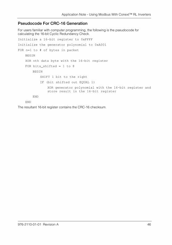
Pseudocode For CRC-16 Generation
For users familiar with computer programming, the following is the pseudocode for calculating the 16-bit Cyclic Redundancy Check.
Initialize a 16-bit register to 0xFFFF
Initialize the generator polynomial to 0xA001
FOR n=1 to # of bytes in packet
BEGIN
XOR nth data byte with the 16-bit register
FOR bits_shifted = 1 to 8
BEGIN
SHIFT 1 bit to the right
IF (bit shifted out EQUAL 1)
XOR generator polynomial with the 16-bit register andstore result in the 16-bit register
END
END
The resultant 16-bit register contains the CRC-16 checksum.
976-2110-01-01 Revision A 46
Application Note - Using Modbus With Conext™ RL Inverters
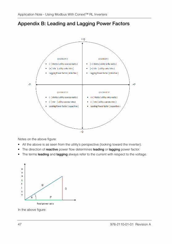
Appendix B: Leading and Lagging Power Factors
Notes on the above figure:
• All the above is as seen from the utility’s perspective (looking toward the inverter).
• The direction of reactive power flow determines leading or lagging power factor.
• The terms leading and lagging always refer to the current with respect to the voltage.
In the above figure:
47 976-2110-01-01 Revision A

Application Note - Using Modbus With Conext™ RL Inverters
• S = Apparent power; has dimensions of volt-amps (VA)
• P = Active or real power; has dimensions of watts (W)
• Q = Reactive power; has dimensions of volt-amp-reactive (VAr)
• PF = power factor; has no units. It is defined as the cosine of angle (the ratio of P over S)
976-2110-01-01 Revision A 48
Application Note - Using Modbus With Conext™ RL Inverters
Schneider Electric, the Schneider Electric logo, and Conext are trademarks or registered trademarks of the Schneider Electric group of companies. Other trademarks, registered trademarks, and product names are the property of their respective owners and are used herein for identification purposes only.
Copyright © 2014 Schneider Electric SA. No part of this document may be reproduced in any form or disclosed to third parties without the express written consent of:Schneider Electric SA35 rue Joseph Monier92500 Rueil Malmaison - FranceThis documentation may be revised and content hereof changed from time to time without obligation to notify any person or entity or to organize such revisions or changes unless required to do so by prior arrangement.
Exclusion for DocumentationUNLESS SPECIFICALLY AGREED TO IN WRITING, SELLER(A) MAKES NO WARRANTY AS TO THE ACCURACY, SUFFICIENCY OR SUITABILITY OF ANY TECHNICAL OR OTHER INFORMATION PROVIDED IN ITS MANUALS OR OTHER DOCUMENTATION;(B) ASSUMES NO RESPONSIBILITY OR LIABILITY FOR LOSSES, DAMAGES, COSTS OR EXPENSES, WHETHER SPECIAL, DIRECT, INDIRECT, CONSEQUENTIAL OR INCIDENTAL, WHICH MIGHT ARISE OUT OF THE USE OF SUCH INFORMATION. THE USE OF ANY SUCH INFORMATION WILL BE ENTIRELY AT THE USER’S RISK; AND(C) REMINDS YOU THAT IF THIS MANUAL IS IN ANY LANGUAGE OTHER THAN ENGLISH, ALTHOUGH STEPS HAVE BEEN TAKEN TO MAINTAIN THE ACCURACY OF THE TRANSLATION, THE ACCURACY CANNOT BE GUARANTEED. APPROVED CONTENT IS CONTAINED WITH THE ENGLISH LANGUAGE VERSION WHICH IS POSTED AT WWW.SCHNEIDER-ELECTRIC.COM.
Date: January 2014 Revision: Revision A Document Number: 976-2110-01-01
Contact Informationwww.schneider-electric.com
? ?N. America 1 408 987 6255 1 925 245 1022 re.techsupport@schneider-
electric.com
France +33 (0) 825 012 999
Deutschland +49 (0) 180 575 3 575 +49 (0) 2102 404 7101 [email protected]
España +34 902 101813 +34 93 305 5026 [email protected]
L'Italia +39 035 4151111 +39 035 4153200 [email protected]
Nederland 0031 235 124124 0031 235 124111 [email protected]
For other country details, contact your local Schneider Electric Sales Representative or visit our website at:http://www.schneider-electric.com/sites/corporate/en/support/operations/local-operations/local-operations.page
49 976-2110-01-01 Revision A