Embed Size (px)
Citation preview
8/13/2019 Modal Design in Structural Dynamics
http://slidepdf.com/reader/full/modal-design-in-structural-dynamics 1/8
Colorado School of Mines – EGGN 557 – Structural Dynamics
Class Notes by Professor Panos D. Kiousis
4/30/2013 Page 1 of 8
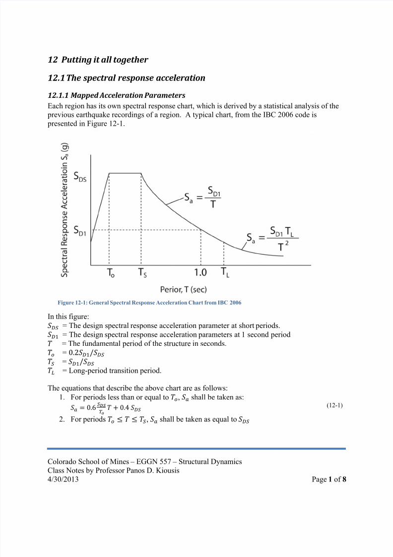
12 Putting it all together
12.1 The spectral response acceleration
12.1.1 Mapped Acceleration Parameters
Each region has its own spectral response chart, which is derived by a statistical analysis of the previous earthquake recordings of a region. A typical chart, from the IBC 2006 code is
presented in Figure 12-1.
In this figure:
= The design spectral response acceleration parameter at short periods.
= The design spectral response acceleration parameters at 1 second period
= The fundamental period of the structure in seconds.
=
=
= Long-period transition period.
The equations that describe the above chart are as follows:1. For periods less than or equal to , shall be taken as:
(12-1)
2. For periods , shall be taken as equal to
Figure 12-1: General Spectral Response Acceleration Chart from IBC 2006

8/13/2019 Modal Design in Structural Dynamics
http://slidepdf.com/reader/full/modal-design-in-structural-dynamics 2/8
Colorado School of Mines – EGGN 557 – Structural Dynamics
Class Notes by Professor Panos D. Kiousis
4/30/2013 Page 2 of 8
3. For periods , shall be taken as
(12-2)
4. For periods , shall be taken as
(12-3)
The above parameters are calculated based on the mapped acceleration parameters and (can be obtained at USGS web site http://earthquake.usgs.gov/hazards/apps/map/), and are adjusted
for site classification (Tables 12-1 through 12-3)
TABLE 12-1 SITE CLASS DEFINITIONS
SITE
CLASS SOIL PROFILE NAME
AVERAGE PROPERTIES IN TOP 100 feet, SEE SECTION 1613.5.5
Soil shear wave velocity, v S , (ft/s) Standard penetration resistance, N Soil undrained shear strength, s u ,(psf)
A Hard rock v s > 5,000 N/A N/A
B Rock 2,500 < v s ≤ 5,000 N/A N/A
CVery dense soil and soft
rock1,200 < v s ≤ 2,500 N > 50 su ≥ 2,000
D Stiff soil profile 600 ≤ v s ≤ 1,200 15 ≤ N ≤ 50 1,000 ≤ su ≤ 2,000
E Soft soil profile v s < 600 N < 15 su < 1,000
E —
Any profile with more than 10 feet of soil having the following characteristics:
1. Plasticity index PI > 20,2. Moisture content w ≥ 40%, and
3. Undrained shear strength ̅ < 500 psf
F —
Any profile containing soils having one or more of the following characteristics:1. Soils vulnerable to potential failure or collapse under seismic loading such as liquefiable soils, quick
and highly sensitive clays, collapsible weakly cemented soils.
2. Peats and/or highly organic clays ( H > 10 feet of peat and/or highly organic clay where H = thicknessof soil)
3. Very high plasticity clays ( H >25 feet with plasticity index PI >75)
4. Very thick soft/medium stiff clays ( H >120 feet)
Table 12-2 – Values of Site Coefficient
Site Class
Mapped spectral response acceleration at short period
A 0.8 0.8 0.8 0.8 0.8
B 1.0 1.0 1.0 1.0 1.0
C 1.2 1.2 1.1 1.0 1.0
D 1.6 1.4 1.2 1.1 1.0
E 2.5 1.7 1.2 0.9 0.9
F Note b Note b Note b Note b Note b
a. Use straight-line interpolation for intermediate values of mapped spectral acceleration at short period,
b. Values shall be determined in accordance with section 11.4.7 of ASCE 7
Table 12-3 – Values of Site Coefficient
Site Class
Mapped spectral response acceleration at 1-second period
A 0.8 0.8 0.8 0.8 0.8
B 1.0 1.0 1.0 1.0 1.0C 1.7 1.6 1.5 1.4 1.3
D 2.4 2.0 1.8 1.6 1.5
E 3.5 3.2 2.8 2.4 2.4
F Note b Note b Note b Note b Note b
a. Use straight-line interpolation for intermediate values of mapped spectral acceleration at 1-second period b. Values shall be determined in accordance with section 11.4.7 of ASCE 7

8/13/2019 Modal Design in Structural Dynamics
http://slidepdf.com/reader/full/modal-design-in-structural-dynamics 3/8
Colorado School of Mines – EGGN 557 – Structural Dynamics
Class Notes by Professor Panos D. Kiousis
4/30/2013 Page 3 of 8
12.1.2 Adjusted Spectral Response based on Site
The maximum considered earthquake spectral response acceleration for short periods, , and
at 1-second period , adjusted for site class effects, are as follows: (12-4)
and
(12-5)where,
= Site coefficient defined in Table 12-2;
= Site coefficient defined in Table 12-3.
12.1.3 Adjusted Spectral Response for Design
The five-percent damped design spectral response acceleration at short periods and at 1-
second period , shall be determined as follows:
(12-6)
and
(12-7)
where,
= The maximum considered earthquake spectral response accelerations for short period;
= The maximum considered earthquake spectral response accelerations for 1-second period;
12.2 Modal Response of a Structure
Let us consider now a shear frame structure that has floors (degrees of freedom). Thus, we can
calculate natural periods , and modal displacement vectors: .
For the mode, the base shear is calculated as:
(12-8)
where
is an expression of the modal mass, i.e. it is the portion of the mass that participates in
the mode;
is the weight that corresponds to mass , and is equal to .
is the spectral acceleration (Figure 12-1) that corresponds to the natural period of the
mode
The participating mass is calculated as:
∑
∑
(12-9)
Similarly, the participating weight is calculated as:
∑
∑
(12-10)
where

8/13/2019 Modal Design in Structural Dynamics
http://slidepdf.com/reader/full/modal-design-in-structural-dynamics 4/8
Colorado School of Mines – EGGN 557 – Structural Dynamics
Class Notes by Professor Panos D. Kiousis
4/30/2013 Page 4 of 8
is the mass lumped at the floor level, and is the modal displacement of the floor.
The base shear for the mode is distributed to each floor as follows (in proportion to thefloor inertia):
∑
(12-11)
Equation (12-11) indicates that the shear force of the
floor is calculated by a tributary expression, where the ratio ∑
is the percent of inertia force of the floor
compared to the total inertia force.
12.3 Example of Implementation
12.3.1 Problem Statement
Calculate the shear forces and bending moments for the
shear frame of Figure 12-2. This shear frame is to be
built in Salt Lake Utah, at coordinates (Latitude = 40.7,
and Longitude -111.9), on a site with a “C”classification, according to the geotechnical report.
12.3.2 Seismic Data
Based on the data provided by USGS web site
http://earthquake.usgs.gov/hazards/apps/map/, the
seismic parameters for the site are as presented in Table12-1:
Table 12-1: Seismic Parameters
Seismic Parameter Probability Magnitude (g)PGA 2% in 50 yrs 0.72
2% in 50 yrs 1.83
2% in 50 yrs 0.54
Based on the site classification and the magnitude of , (Table 12-2). Similarly,
(Table 12-3).
The site specific parameters and are calculated according to equations (12-4) and (12-5)accordingly as:
, and
Based on Equations (12-6) and (12-7), the design parameters are calculated:
and
Figure 12-1 can now be produced, specifically for this site, where:
Figure 12-2: Definition of Shear Frame

8/13/2019 Modal Design in Structural Dynamics
http://slidepdf.com/reader/full/modal-design-in-structural-dynamics 5/8
Colorado School of Mines – EGGN 557 – Structural Dynamics
Class Notes by Professor Panos D. Kiousis
4/30/2013 Page 5 of 8
The outcome is presented in Figure 12-3
12.3.3 Structural Modes
A modal analysis of the shear frame produces the results presented in Table 12-2:
Table 12-2: Natural periods and modes of shear frame
T n → 0.494 0.169 0.107 0.084 0.073
m
3000 1.000 1.000 1.000 1.000 1.000
3000 1.919 1.310 0.285 -0.831 -1.683
3000 2.683 0.715 -0.919 -0.310 1.831
3000 3.229 -0.373 -0.546 1.088 -1.398
3000 3.513 -1.204 0.764 -0.594 0.521
12.3.4 Modal Analysis
1. Evaluation of participating masses per modeBased on equation (12-9) we calculated the mass that participates in the first mode:
Similarly
Figure 12-3: Site-specific spectral response acceleration chart

8/13/2019 Modal Design in Structural Dynamics
http://slidepdf.com/reader/full/modal-design-in-structural-dynamics 6/8
Colorado School of Mines – EGGN 557 – Structural Dynamics
Class Notes by Professor Panos D. Kiousis
4/30/2013 Page 6 of 8
and
Note that ∑ , which is the total mass of the system.
2. Evaluation of the modal acceleration for each participating mass
Using the structural natural periods for each mode and Figure 12-3, we can calculate the
modal acceleration for each participating mass. The outcome of this process is presented
in Table 12-3.
Table 12-3: Evaluation of modal accelerations and base shears
0.494 9.29 122,611
0.169 11.97 15,650
0.107 11.97 4,347
0.084 11.97 1,348
0.073 11.62 273
3. Evaluation of base shear
Using equation 12-8, the base shear for each mode is evaluated as the product of the
modal participating mass and the corresponding modal acceleration (Last column of
Table 12-3).
4. Base shear distribution to each floor as nodal load.The base shear is considered to be the result of the inertia forces that are acting to each
floor. As such, it is distributed to each floor using equation (12-11).These calculations are tabulated in Table 12.4
Table 12-4 : Distribution of base shear to each story for each mode
Story v 1 v 2 v 3 v 4 v 5
N N N N N
1 9933 10803 7457 3816 1006
2 19062 14149 2123 -3171 -1693
3 26646 7728 -6853 -1182 18424 32071 -4027 -4073 4153 -1406
5 34899 -13003 5694 -2268 524
An example of the application of the shear nodal loads due to the second mode is presented in Figure 12-4.

8/13/2019 Modal Design in Structural Dynamics
http://slidepdf.com/reader/full/modal-design-in-structural-dynamics 7/8

8/13/2019 Modal Design in Structural Dynamics
http://slidepdf.com/reader/full/modal-design-in-structural-dynamics 8/8
Colorado School of Mines – EGGN 557 – Structural Dynamics
Class Notes by Professor Panos D. Kiousis
4/30/2013 Page 8 of 8
It is demonstrated that for this problem, the floor shears can be reasonably approximated by the cumulative effects of the first and second mode, or even by considering the first
mode alone.
The floor shear must be distributed to the individual columns. For pure translationmodes, this distribution is proportional to the shear stiffness contribution of each column
to the total shear stiffness of the floor. For example, in a three column system with
individual column stiffnesses , , and , the floor stiffness is and the
floor shear is distributed as follows:
,
,
In the example of Figure 12-2, that we consider here, the two columns have equal
stiffness, and thus, each column resists ½ of the floor shear.6. Column bending moment.
Assuming that each story has a height of 3 meters, then each column is subjected tonodal moments
. The resulting seismic bending moment diagram per column
is presented in figure 12-6.
0 50000 100000 150000
1
2
3
4
5
Floor Shear (N)
F l o o r L e v e l
Sum of all modes
Sum of 1st and 2nd Modes
First Mode
Figure 12-5: Floor shear diagram
Figure 12-6: Seismic bending moment diagram for a column based on the cumulative shears for all five modes


![6th Internationa] Modal Analysis ConferenceDamped Systems D. L. Cronin Modal Identities In Structural Dynamics 30-35 B. P. Wang Further Study On The Modal Damping Ratio Matrix For](https://img.pdfslide.us/doc/110x75/602214670d43a7149a27c0ef/6th-internationa-modal-analysis-damped-systems-d-l-cronin-modal-identities-in.jpg)