Embed Size (px)
Citation preview
IJSRD - International Journal for Scientific Research & Development| Vol. 4, Issue 03, 2016 | ISSN (online): 2321-0613
All rights reserved by www.ijsrd.com 1415
Modal Analysis of Cable Stayed Bridge (Bandra-Worli Sea Link) using
ANSYS Ms. Ekta R. Vishwakarma1 Ms. Nishigandha A. Desai2 Ms. Vrushali R. Gaikwad3 Ms. Kanchan
M. Kadale4 Prof. Dipak Chaudhari5
1,2,3,4Student 5Professor 1,2,3,4,5Vidyavardhini’s College of Engineering and Technology
Abstract— This paper provides an analysis of the aesthetic
and structural and vibrational properties of the cable stayed
section of the Bandra-Worli Sea Link. Both theoretical and
software analysis of the bridge have been included.
Information given in this paper helps to interpret the critical
analysis such as the complex construction process and the
analytical method used for the bridge. BandraWorli Sea Link
has become more popular in handling traffic, thus a thorough
calculation and analysis of natural frequency of the bridge
needs to be examined with the vibrational frequency of the
environmental and traffic conditions to avoid resonance.
Modal Analysis using ANSYS helps to determine the natural
frequency of the bridge and understand the various modes
shapes and makes it possible to study the limits, reasons and
prevent the bridge from collapsing. Giving context to the
paper.
Key words: Bandra-Worli Sea-Link, BWSL Bridge, Cable-
Stayed, Modal Analysis, Mumbai
I. INTRODUCTION
A. Modal Analysis:
Modal analysis is the study of the dynamic properties of
structures under vibrational excitation. Modal analysis is the
field of measuring and analyzing the dynamic response of
structures and or fluids during excitation.
Modern day modal analysis systems are composed
of:
1) Sensors such as transducers (typically accelerometers,
load cells), or non contact via a Laser vibrometer or
stereo-photogrammetric cameras
2) Data acquisition system and an analog-to-digital
converter frontend (to digitize analog instrumentation
signals) and
3) Host PC (personal computer) to view the data and
analyze it.
In structural engineering, Modal Analysis uses the
overall mass and stiffness of a structure to find the various
periods at which it will naturally resonate. These periods of
vibration are very important to note in earthquake
engineering, as it is imperative that a building's natural
frequency does not match the frequency of expected
earthquakes in the region in which the building is to be
constructed. If a structure's natural frequency matches an
earthquake's frequency, the structure may continue to
resonate and experience structural damage.
Modal analysis is also important in structures such
as bridges where the engineer should attempt to keep the
natural frequencies away from the frequencies of people
walking on the bridge. This may not be possible and for this
reasons when groups of people are to walk along a bridge,
for example a group of soldiers, the recommendation is that
they break their step to avoid possibly significant excitation
frequencies. Other natural excitation frequencies may exist
and may excite a bridge's natural modes. Engineers tend to
learn from such examples (at least in the short term) and
more modern suspension bridges take account of the
potential influence of wind through the shape of the deck,
which might be designed in aerodynamic terms to pull the
deck down against the support of the structure rather than
allow it to lift.
1) What is Natural Frequency?
Natural Frequency is the frequency at which a system tends
to oscillate in the absence of any driving or damping force.
Free vibrations of any elastic body are called natural
vibrations and occur at a frequency called the natural
frequency. Natural vibrations are different from forced
vibrations which happen at frequency of applied force
(forced frequency).
2) What is Resonance?
"The state of a system in which an abnormally large
vibration is produced in response to an external stimulus,
occurring when the frequency of the stimulus is the same or
nearly the same as the natural vibration frequency of the
system". Resonance occurs when a structure or material
naturally oscillates at high amplitude at a specific frequency.
This frequency is known as a structural resonant frequency.
Typically a structure will have many resonant frequencies.
3) What are Mode Shapes?
A Mode Shape is a specific pattern of vibration executed by
a mechanical system at a specific frequency. This mode
shape can be determined by Eigen value of vibration
equation like single or two degree of freedom system.
Different mode shapes will be associated with different
frequencies. The experimental technique of modal analysis
discovers these mode shapes and the frequencies. Mode
shape is the shapes of the beam at different natural
frequency.
B. Cable Stayed Bridge:
A cable stayed bridge has one or more towers (pylons) from
which cables support the bridge deck. Cable stayed bridges
may appear to be similar to suspension bridges, but in fact
they are quite different in principle and in their construction.
In cable stayed bridges, the towers are the primary load
bearing structures which transmit the bridge loads to the
ground. There are four major classes of cable-stayed
bridges: harp, mono, star and fan.
C. Bandra-Worli Sea Link:
The Bandra-Worli Sea Link (BWSL) is a civil engineering
marvel spanning an arc of the Mumbai coastline. With its
cable-stayed towers soaring gracefully skywards, the sea
link is a reflection of the modern infrastructure that Mumbai
is adding in its progress towards becoming a world-class
city. The BWSL project is a part of the Western Freeway
Sea Project, which, in turn, is a part of a larger proposal to
upgrade the road transportation network of greater Mumbai.
Modal Analysis of Cable Stayed Bridge (Bandra-Worli Sea Link) using ANSYS
(IJSRD/Vol. 4/Issue 03/2016/375)
All rights reserved by www.ijsrd.com 1416
In the first phase it will connect Bandra to Worli
whereas in the subsequent phases the plans are to take it
further to Haji Ali and then to Nariman Point. It is a
connecting bridge linking the city of Mumbai with its
western suburbs and has the potential to bring about
permanent and far reaching changes in the travel patterns of
the area. The Bandra-Worli Sea Link is primarily meant to
provide an alternative to the Mahim Causeway route that is
presently the only connection between South Mumbai and
the Western and Central suburbs. The project starts from the
interchange at Mahim intersection, i.e. intersection of
Western Express Highway and Swami Vivekanand Road at
the Bandra end, and connects it to Khan Abdul Gaffar Khan
Road at the Worli end.
The project has been commissioned to offer a
quicker alternative to the northsouth traffic that presently
amounts to approximately 125,000 cars a day. The project
has been commissioned by the Maharashtra State Road
Development Corporation Ltd (MSRDC) and the
Maharashtra Government and is being built by HCC
(Hindustan Construction Company). As a builder of
landmark infrastructure projects around the country, HCC
has handled numerous challenges both in terms of location
and technology. The BWSL project offered HCC an
opportunity to accomplish one more feat: to construct an
eight-lane freeway over the open sea for the first time in
India.
1) Highlights in Brief:
India's first bridge to be constructed in open-sea
conditions
4.7 km, twin, 4-lane independent carriageway bridge
across the open sea
16-lane toll plaza with 20-m wide promenade together
with state-of-the-art traffic
monitoring, surveillance, information and control
systems
2342 pre-cast segments for total bridge with varied
width
40,000 MT of reinforcement, 23,0000 cum of concrete,
5,400 MT of Post tensioning strands and bars used
Osterberg cell technology used for the first time in
India to check pile strength (for up to 9600 MT).
Engagement of Asian Hercules, one of the largest
floating shear leg crane in the world for Shifting 1,260
MT launching truss from Bandra end to Worli end of
the main cable stay bridge
Largest span for cable-stayed bridge in India
Up to 25-m high pier in open sea, giving ample
headroom to marine traffic
Use of Polytron Disc in bearings on piers for the first
time in India
2) Project Overview:
The entire project was originally conceived as one large
project comprising, different components, but in order to
accelerate the overall construction schedule, the project has
been divided into five construction packages :-
Package I: Construction of flyover over Love Grove
junction at Worli
Package II: Construction of cloverleaf interchange at
Mahim intersection
Package III: Construction of solid approach road from
the Mahim intersection up to the start of the Toll Plaza
on the Bandra side and a public promenade
Package IV: Construction of Cable-Stayed Bridges
together with viaduct approaches extending from Worli
up to the Toll Plaza at Bandra end, Intelligent Bridge
System (IBS)
Package V: Improvement to Khan Abdul Gaffar Khan
Road.
3) Cable Stayed Section of Bandra-Worli Sea Link:
The cable stayed portion of the Bandra channel is 600
meters in overall length between expansion joints and
consists of two 250 meter cable supported main spans
flanked by 50 meters conventional approach spans. A centre
tower, with an overall height of 128 meters above pile cap
level, supports the superstructure by means of four planes of
cable stay in a semi-harp arrangement. Cable spacing is 6.0
meters along the bridge deck.
A total of 264 cable stays are used at Bandra
channel with cable lengths varying from approximately 85
meters minimum to nearly 250 meters maximum. The tower
is cast in-situ reinforced concrete using the climbing form
method of construction. The overall tower configuration is
an inverted "Y" shape with the inclined legs oriented along
the axis of the bridge. Tower cable anchorage recesses are
achieved by use of formed pockets and transverse and
longitudinal bar post-tensioning is provided in the tower
head to resist local cable forces.
II. BRIDGE PARTS
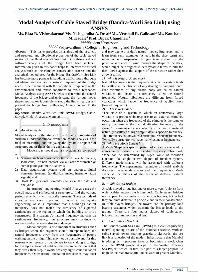
A. Deck:
The deck or road bed is the roadway surface of a cable-
stayed bridge. The deck can be made of different materials
such as steel, concrete or composite steel-concrete. The
choice of material for the bridge deck determines the overall
cost of the construction of cable stayed bridges. The weight
of the deck has significant impact on the required stay
cables, pylons, and foundations. The composite steel-
concrete deck of Bandra-Worli sea link is composed of two
structural edge girders. These girders are attached by
transverse steel floor beams. The precast reinforced concrete
deck is supported by these two main girders.
Fig. 1: Deck Cross Section
1) Dead Loads:
Dead loads are taken to be just the weight of the precast
deck section; any reinforcing steel is assumed to be
accounted for by the increased density of the concrete.
Density of reinforced concrete = 2400 kg/m3=24
KN/m3
Cross-sectional deck area =7.2m2
Force per unit length on deck=Density × Area=24 ×
7.2=172.8 KN/m
Modal Analysis of Cable Stayed Bridge (Bandra-Worli Sea Link) using ANSYS
(IJSRD/Vol. 4/Issue 03/2016/375)
All rights reserved by www.ijsrd.com 1417
2) Seismic Loading:
Mumbai is in a geographically sensitive area for
earthquakes. In general cable stayed structures are extremely
effective at coping with ground displacements due to them
“resting on a limited number of point supports”. However
differential movement of the supports can cause damage to
the structure, this is fairly common with a bridge of this size
due to the separation and therefore geological variation
between the ground beneath them. Particularly affecting the
junctions between piers and the deck. For this reason
horizontal affects are much more hazardous than vertical
movements.
The Bandra-Worli Sea link design fulfils the
criteria laid out in the Indian standard for earthquake design
in bridges IS 1893 (1984). In the introduction to the codes it
is stated that all earthquake resistant structures should have
good structural configuration, good lateral stability, stiffness
and ductility. The structural form of a cable stayed structure
delivers adequate ductility and the A-frame shape of the
piers along with the generous sizing of the foundations
provides a certain degree of stiffness and lateral stability.
There are a number of other minor features which contribute
to the bridges seismic design such as using DISKTRON
bearings which allow complete rotation in both longitudinal
and transverse directions.
3) Natural Frequency:
The effects of vibration on the structure of a bridge can be
great. Examples of where natural frequency issues of a
bridge have caused problems are the Tacoma Narrows
bridge and the Millennium Bridge crossing the Thames.
These two examples highlight how the frequencies of live
loads apart from wind have to be considered. It
demonstrates that the bridge should be analyzed bearing in
mind not only collapse but the comfort of the users.
Therefore a range of frequencies should be considered to
confirm that the bridge will not suffer excessive movement
due to having a natural frequency which matches the
frequency of any oscillatory loads applied to the bridge.
“Without damaging the structure, the vibrations due to wind
and traffic can inconvenience users. These physiological
effects are generally very subjective experiences”. These
physiological effects are acceptable when the natural
frequency of the bridge is:
5Hz<f0<75Hz
Using:
fo=𝐶2
2𝜋𝑙√
𝐸𝐼𝑔
𝑀
The value of C is π because the 2 spans on opposite
sides of the piers are equal.
L = 250 m – the longest span occurs at Worli end
suspension section.
E = 30 GPa
I = 17m4
So:
fo=π2
2π×250√
30×106×17×9.81
272.5= 26.923 Hz
This is within acceptable bounds.
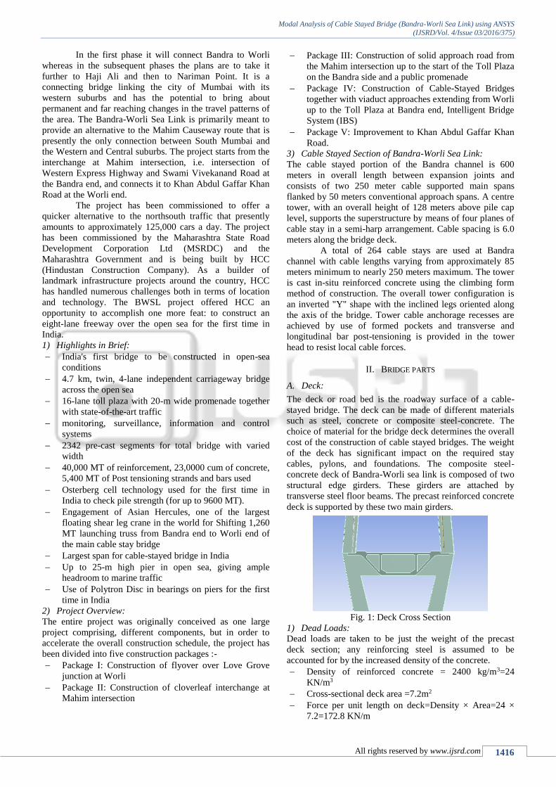
B. Pylon:
Pylons are arguably the most important components of a
cable stayed bridge. The main span bridge has 2 pylons,
each with 4 legs each tower is inclined towards the other by
10°, eventually merging at 98 m above deck to become a
single tower. Transverse and longitudinal post - tensioning
is provided in the tower head to resist local cable forces. The
single tower is tapered towards the very top. Beneath the
superstructure of the bridge the 4 legs merge to 2 points
which are carried into the ground through the pile caps.
The salient characteristics of the pylon tower that
make it complex and challenging from the point of view of
constructability are as follows:
The section decreases gradually with height;
There are horizontal grooves at every 3m height and
vertical grooves for circular portion that requires
special form liners as well as it requires attention for
de-shuttering;
The tower legs are inclined in two directions, which
creates complexities in alignment and climbing of
soldiers.
1) Design of Tower Legs:
The complex pylon geometry was another challenge for
surveyors. Coupled with geometry, the construction stage
analysis indicated leaning and progressively increasing
inward inclination of pylon legs during construction. HCC's
Principal Surveyor devised a sophisticated technology to
measure coordinates through a combination of total station
and prisms mounted on pylon legs. The temperature and
construction stage analysis factors were applied to derive the
corrected coordinates. The pylon legs were constructed
within an accuracy of ±5mm, which speaks volumes about
the technique employed.
Fig. 2: Tower Legs
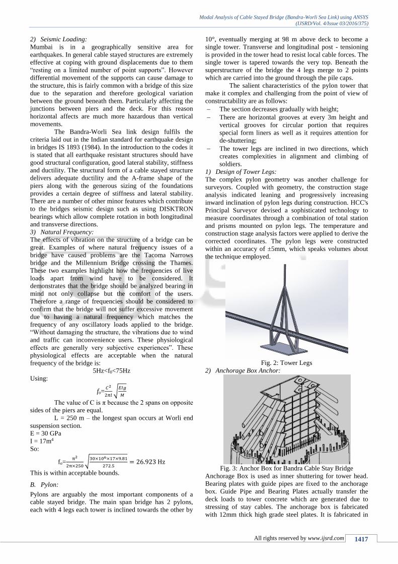
2) Anchorage Box Anchor:
Fig. 3: Anchor Box for Bandra Cable Stay Bridge
Anchorage Box is used as inner shuttering for tower head.
Bearing plates with guide pipes are fixed to the anchorage
box. Guide Pipe and Bearing Plates actually transfer the
deck loads to tower concrete which are generated due to
stressing of stay cables. The anchorage box is fabricated
with 12mm thick high grade steel plates. It is fabricated in
Modal Analysis of Cable Stayed Bridge (Bandra-Worli Sea Link) using ANSYS
(IJSRD/Vol. 4/Issue 03/2016/375)
All rights reserved by www.ijsrd.com 1418
pieces and then bolted at tower head portion. The bearing
plates and guide pipes of anchorage box are galvanized and
the remaining portion was painted with anticorrosive
polyurethane based paint. Anchorage boxes are fixed with
the help of co-ordinate system for accurately fixing the
anchorage point and angle of stay cable.
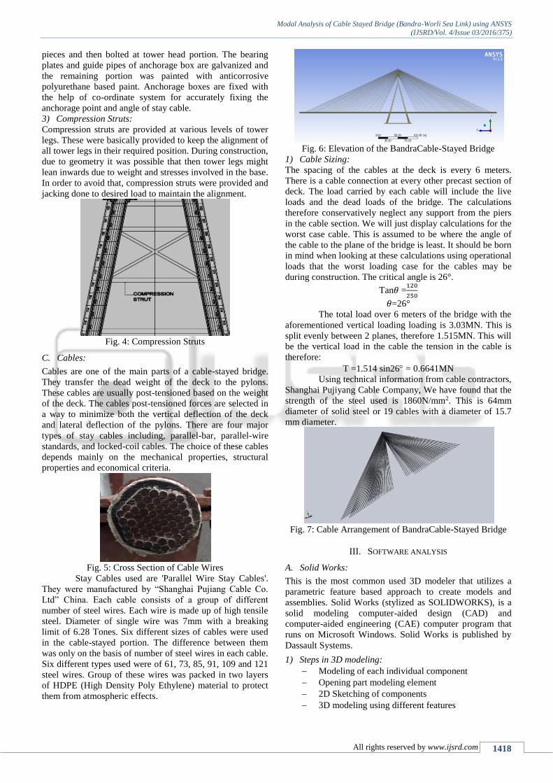
3) Compression Struts:
Compression struts are provided at various levels of tower
legs. These were basically provided to keep the alignment of
all tower legs in their required position. During construction,
due to geometry it was possible that then tower legs might
lean inwards due to weight and stresses involved in the base.
In order to avoid that, compression struts were provided and
jacking done to desired load to maintain the alignment.
Fig. 4: Compression Struts
C. Cables:
Cables are one of the main parts of a cable-stayed bridge.
They transfer the dead weight of the deck to the pylons.
These cables are usually post-tensioned based on the weight
of the deck. The cables post-tensioned forces are selected in
a way to minimize both the vertical deflection of the deck
and lateral deflection of the pylons. There are four major
types of stay cables including, parallel-bar, parallel-wire
standards, and locked-coil cables. The choice of these cables
depends mainly on the mechanical properties, structural
properties and economical criteria.
Fig. 5: Cross Section of Cable Wires
Stay Cables used are 'Parallel Wire Stay Cables'.
They were manufactured by “Shanghai Pujiang Cable Co.
Ltd” China. Each cable consists of a group of different
number of steel wires. Each wire is made up of high tensile
steel. Diameter of single wire was 7mm with a breaking
limit of 6.28 Tones. Six different sizes of cables were used
in the cable-stayed portion. The difference between them
was only on the basis of number of steel wires in each cable.
Six different types used were of 61, 73, 85, 91, 109 and 121
steel wires. Group of these wires was packed in two layers
of HDPE (High Density Poly Ethylene) material to protect
them from atmospheric effects.
Fig. 6: Elevation of the BandraCable-Stayed Bridge
1) Cable Sizing:
The spacing of the cables at the deck is every 6 meters.
There is a cable connection at every other precast section of
deck. The load carried by each cable will include the live
loads and the dead loads of the bridge. The calculations
therefore conservatively neglect any support from the piers
in the cable section. We will just display calculations for the
worst case cable. This is assumed to be where the angle of
the cable to the plane of the bridge is least. It should be born
in mind when looking at these calculations using operational
loads that the worst loading case for the cables may be
during construction. The critical angle is 26°.
Tan𝜃 =120
250
𝜃=26°
The total load over 6 meters of the bridge with the
aforementioned vertical loading loading is 3.03MN. This is
split evenly between 2 planes, therefore 1.515MN. This will
be the vertical load in the cable the tension in the cable is
therefore:
T =1.514 sin26 = 0.6641MN
Using technical information from cable contractors,
Shanghai Pujiyang Cable Company, We have found that the
strength of the steel used is 1860N/mm2. This is 64mm
diameter of solid steel or 19 cables with a diameter of 15.7
mm diameter.
Fig. 7: Cable Arrangement of BandraCable-Stayed Bridge
III. SOFTWARE ANALYSIS
A. Solid Works:
This is the most common used 3D modeler that utilizes a
parametric feature based approach to create models and
assemblies. Solid Works (stylized as SOLIDWORKS), is a
solid modeling computer-aided design (CAD) and
computer-aided engineering (CAE) computer program that
runs on Microsoft Windows. Solid Works is published by
Dassault Systems.
1) Steps in 3D modeling:
Modeling of each individual component
Opening part modeling element
2D Sketching of components
3D modeling using different features
Modal Analysis of Cable Stayed Bridge (Bandra-Worli Sea Link) using ANSYS
(IJSRD/Vol. 4/Issue 03/2016/375)
All rights reserved by www.ijsrd.com 1419
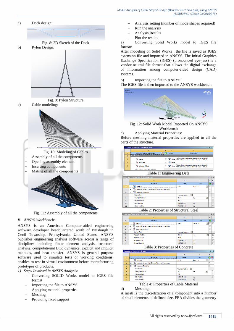
a) Deck design:
Fig. 8: 2D Sketch of the Deck
b) Pylon Design:
Fig. 9: Pylon Structure
c) Cable modeling:
Fig. 10: Modeling of Cables
Assembly of all the components
Opening assembly element
Inserting components
Mating of all the components
Fig. 11: Assembly of all the components
B. ANSYS Workbench:
ANSYS is an American Computer-aided engineering
software developer headquartered south of Pittsburgh in
Cecil Township, Pennsylvania, United States. ANSYS
publishes engineering analysis software across a range of
disciplines including finite element analysis, structural
analysis, computational fluid dynamics, explicit and implicit
methods, and heat transfer. ANSYS is general purpose
software used to simulate tests or working conditions,
enables to test in virtual environment before manufacturing
prototypes of products.
1) Steps Involved in ANSYS Analysis:
Converting SOLID Works model to IGES file
format
Importing the file to ANSYS
Applying material properties
Meshing
Providing fixed support
Analysis setting (number of mode shapes required)
Run the analysis
Analysis Results
Plot the results
a) Converting Solid Works model to IGES file
format:
After modeling on Solid Works , the file is saved as IGES
extension file and imported in ANSYS. The Initial Graphics
Exchange Specification (IGES) (pronounced eye-jess) is a
vendor-neutral file format that allows the digital exchange
of information among computer-aided design (CAD)
systems.
b) Importing the file to ANSYS:
The IGES file is then imported to the ANSYS workbench.
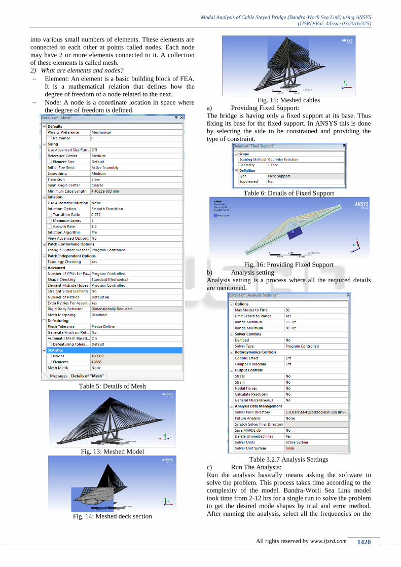
Fig. 12: Solid Work Model Imported On ANSYS
Workbench
c) Applying Material Properties:
Before meshing material properties are applied to all the
parts of the structure.
Table 1: Engineering Data
Table 2: Properties of Structural Steel
Table 3: Properties of Concrete
Table 4: Properties of Cable Material
d) Meshing:
A mesh is the discretization of a component into a number
of small elements of defined size. FEA divides the geometry
Modal Analysis of Cable Stayed Bridge (Bandra-Worli Sea Link) using ANSYS
(IJSRD/Vol. 4/Issue 03/2016/375)
All rights reserved by www.ijsrd.com 1420
into various small numbers of elements. These elements are
connected to each other at points called nodes. Each node
may have 2 or more elements connected to it. A collection
of these elements is called mesh.
2) What are elements and nodes?
Element: An element is a basic building block of FEA.
It is a mathematical relation that defines how the
degree of freedom of a node related to the next.
Node: A node is a coordinate location in space where
the degree of freedom is defined.
Table 5: Details of Mesh
Fig. 13: Meshed Model
Fig. 14: Meshed deck section
Fig. 15: Meshed cables
a) Providing Fixed Support:
The bridge is having only a fixed support at its base. Thus
fixing its base for the fixed support. In ANSYS this is done
by selecting the side to be constrained and providing the
type of constraint.
Table 6: Details of Fixed Support
Fig. 16: Providing Fixed Support
b) Analysis setting
Analysis setting is a process where all the required details
are mentioned.
Table 3.2.7 Analysis Settings
c) Run The Analysis:
Run the analysis basically means asking the software to
solve the problem. This process takes time according to the
complexity of the model. Bandra-Worli Sea Link model
took time from 2-12 hrs for a single run to solve the problem
to get the desired mode shapes by trial and error method.
After running the analysis, select all the frequencies on the
Modal Analysis of Cable Stayed Bridge (Bandra-Worli Sea Link) using ANSYS
(IJSRD/Vol. 4/Issue 03/2016/375)
All rights reserved by www.ijsrd.com 1421
screen and go to the SOLVE command. This command will
generate various mode shapes for the selected frequencies.
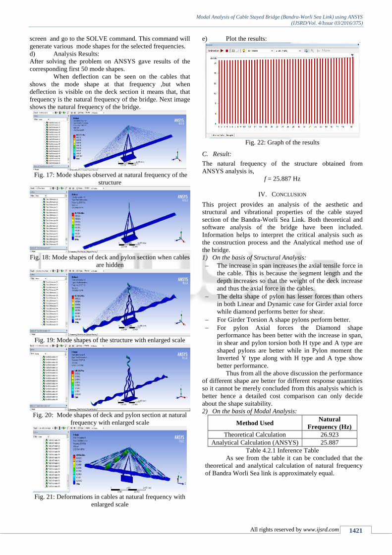
d) Analysis Results:
After solving the problem on ANSYS gave results of the
corresponding first 50 mode shapes.
When deflection can be seen on the cables that
shows the mode shape at that frequency ,but when
deflection is visible on the deck section it means that, that
frequency is the natural frequency of the bridge. Next image
shows the natural frequency of the bridge.
Fig. 17: Mode shapes observed at natural frequency of the
structure
Fig. 18: Mode shapes of deck and pylon section when cables
are hidden
Fig. 19: Mode shapes of the structure with enlarged scale
Fig. 20: Mode shapes of deck and pylon section at natural
frequency with enlarged scale
Fig. 21: Deformations in cables at natural frequency with
enlarged scale
e) Plot the results:
Fig. 22: Graph of the results
C. Result:
The natural frequency of the structure obtained from
ANSYS analysis is,
f = 25.887 Hz
IV. CONCLUSION
This project provides an analysis of the aesthetic and
structural and vibrational properties of the cable stayed
section of the Bandra-Worli Sea Link. Both theoretical and
software analysis of the bridge have been included.
Information helps to interpret the critical analysis such as
the construction process and the Analytical method use of
the bridge.
1) On the basis of Structural Analysis:
The increase in span increases the axial tensile force in
the cable. This is because the segment length and the
depth increases so that the weight of the deck increase
and thus the axial force in the cables.
The delta shape of pylon has lesser forces than others
in both Linear and Dynamic case for Girder axial force
while diamond performs better for shear.
For Girder Torsion A shape pylons perform better.
For pylon Axial forces the Diamond shape
performance has been better with the increase in span,
in shear and pylon torsion both H type and A type are
shaped pylons are better while in Pylon moment the
Inverted Y type along with H type and A type show
better performance.
Thus from all the above discussion the performance
of different shape are better for different response quantities
so it cannot be merely concluded from this analysis which is
better hence a detailed cost comparison can only decide
about the shape suitability.
2) On the basis of Modal Analysis:
Method Used Natural
Frequency (Hz)
Theoretical Calculation 26.923
Analytical Calculation (ANSYS) 25.887
Table 4.2.1 Inference Table
As see from the table it can be concluded that the
theoretical and analytical calculation of natural frequency
of Bandra Worli Sea link is approximately equal.

Modal Analysis of Cable Stayed Bridge (Bandra-Worli Sea Link) using ANSYS
(IJSRD/Vol. 4/Issue 03/2016/375)
All rights reserved by www.ijsrd.com 1422
REFERENCES
Papers:
[1] C.S.W. Davies, “A critical analysis of Bandra Worli
cable stayed bridge, Mumbai”, Proceedings of Bridge
Engineering 2 Conference 2009 April 2009, University
of Bath, Bath, UK.
[2] HCC, Bandra Worli Sea Link Project - Construction
Methods, HCC India Website, [Online] 2008.
[3] Dar Consultants, Bandra Worli Sea Link, [Online]
2008.
[4] Bandra Worli Sea Link - Mumbai, India. Waymarking.
[Online] April 2009.
[5] Scotti, Andrea, “Long Term Behaviour of Cable Stayed
Bridges”, 2003.
[6] LaViolette, Mike et al. Bridge Construction Practices,
2007.
Websites:
[7] www.ansys.com
[8] www.bandraworlisealink.com
[9] www.rajivgandhisealink.com
[10] www.modalanalysis.com
[11] http://en.wikipedia.org/wiki/Bandra-Worli_Sea_Link
[12] http://en.m.wikipedia.org/wiki/Modal_analysis_using_
ANSYS


![Untitled-1 [] · he Bandra-Worli Sea Link, officially called Rajiv Gandhi Sea Link, is a cable-stayed bridge with pre-stressed concrete-steel viaducts on either sides that](https://img.pdfslide.us/doc/110x75/5b6ea5277f8b9afc538e5a00/untitled-1-he-bandra-worli-sea-link-officially-called-rajiv-gandhi-sea.jpg)