Embed Size (px)
Citation preview
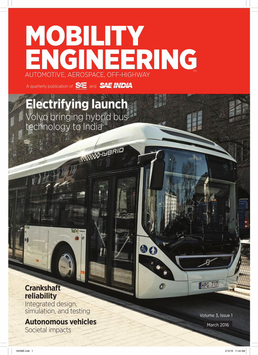
Electrifying launchVolvo bringing hybrid bus technology to India
Crankshaft reliabilityIntegrated design, simulation, and testing
Autonomous vehiclesSocietal impacts
MOBILITY ENGINEERINGAUTOMOTIVE, AEROSPACE, OFF-HIGHWAY
A quarterly publication of and
TM
March 2016
Volume 3, Issue 1
1603ME.indb 1 2/12/16 11:44 AM
Anything for a quiet ride
Find out how we’re making a difference on every scale:
makingabigdifference.com [email protected]
We believe seat adjustment systems are there to enhance driver comfort, not to make distracting noises during driving. By dampening structure-borne vibrations in the seat height adjustment system Saint-Gobain helps you deliver a quieter drive. We can also reduce component wear for a longer life.It’s just one of the ways our teams are working with the world’s automotive engineers to improve the driving experience.
ME Saint-Gobain Ad 0316.qxp_Mobility FP 1/4/16 12:50 PM Page 1
1603ME.indb 2 2/12/16 11:44 AM

40 Autonomous vehicles: impact on society AUTOMOTIVE ELECTRONICS
Self-driving technology offers plenty of promise, but not everything about autonomous vehicles will be a panacea.
42 Crankshaft reliability by integrated design, simulation, and testing AUTOMOTIVE POWERTRAIN
This testing method is proven and beneficial for the design and development of the crankshaft and could be applied to other critical engine components, thereby extending to system reliability.
45 New Engines 2016 AUTOMOTIVE POWERTRAIN
Highlighting the design, engineering, and technologies inside some of the most competitive gasoline and light-duty diesel ICEs.
Features
CoverVolvo is bringing its hybrid bus technology to India in the first half of 2016, promising a fuel-consumption benefit of 39% compared to diesel.
52 Touch and go AEROSPACE AVIONICSAvionics developments are changing life in the cockpit and at airborne work stations.
56 Improving heavy-duty engine component efficiencies OFF-HIGHWAY POWERTRAIN
Cylinder deactivation can improve fuel economy by using a reduced number of cylinders that operate at higher loads and thermal efficiency, while other cylinders are turned off, when the engine operates at partial load conditions. A switching roller finger follower is one of the technologies that help make it work.
CONTENTS
MARCH 2016 1 MOBILITY ENGINEERING
1603ME.indb 1 2/12/16 11:44 AM

Departments 4 Editorial 6 Focus 8 SAEINDIA News 8 SAENIS Efficycle 2015, 15th-18th October 2015
10 Inauguration of Division Offices, 13th October and November 2015, Chennai & Madurai
12 Technical talk, 30th October 2015, Bangalore
12 AWIM Master Teacher Training Program 2015, 12th December 2015, Bangalore
13 AWIM Regional Olympics 5th December 2015, Pune
14 Lecture Meeting, 19th December 2015, Chennai
14 SINE 2015, 13th-24th December 2015, Pune
16 AWIM Regional Olympics, 19th and 30th December 2015, Tirunelveli and Chennai
17 Industry News 17 Rockwell Collins expands India operations
17 Tech Mahindra buys controlling stake in Pininfarina
17 HydraForce strengthens electrohydraulic-controls position in India
18 Magneti Marelli opens plant to produce automated manuals
18 Volvo launches first hybrid buses in India
19 Technology Report 19 Low-friction techniques push advanced city-car
project toward 84-mpg target AUTOMOTIVE POWERTRAIN
21 Clean-sheet design for Proterra’s all-electric city bus OFF-HIGHWAY PROPULSION
22 GE’s clean-sheet turboprop engine to launch with Textron Aviation AEROSPACE PROPULSION
23 OTA reflashing: the challenges and solutions AUTOMOTIVE ELECTRONICS
24 Clamoring for a connection AVIONICS
25 HMIs offer something for everyone COMMERCIAL VEHICLE INTERIORS
26 Secondary loop and heat pump climate control under evaluation once more AUTOMOTIVE INTERIORS
27 SABIC showcases customizable sheet, 3D seat for aircraft interiors AEROSPACE INTERIORS
28 Ford looks to spread Corning’s new lightweight Gorilla Glass beyond the 2017 GT AUTOMOTIVE BODY
30 2016 Civic structure employs ‘first’ partial in-die soft zones AUTOMOTIVE BODY & CHASSIS
31 UCLA researchers develop new strong and lightweight metal nanocomposite AEROSPACE MATERIALS
32 GT350 Mustang features novel composite structural component AUTOMOTIVE MATERIALS
33 Crash testing advances on many fronts AUTOMOTIVE TESTING
34 Evaluating new forestry machines in a fraction of the time OFF-HIGHWAY SIMULATION
36 Aurora Flight Sciences, Stratasys debut at Dubai jet-powered, 3D printed UAV AEROSPACE SIMULATION
36 Surface Generation speeds composites throughput with one-shot stamp-forming process AUTOMOTIVE MANUFACTURING
38 GE scanner enhances defect detection for industrial CT AEROSPACE MANUFACTURING
38 Hot-stamping process from Schuler employs flexible ‘pressure controlled hardening’ AUTOMOTIVE MANUFACTURING
60 Global Vehicles 60 BUDD-e concept forecasts what VW zero-emission
van could be in 2019
61 Airbus looks to expand military product lines
63 Companies Mentioned, Ad Index 64 Q&A Navistar CIO Terry Kline talks about the company’s
vehicle connectivity strategy and its new over-the-air reprogramming technology
HOW DO I KNOW IF I’M TALKING TO AN ENGINEER OR A SALESMAN?
THE ENGINEER’S CHOICE™
Ask Smalley. We have nothing against sales people. But when it comes to differentiating Inconel from Elgiloy or overcoming dimensional variations within a complex assembly, wouldn’t you rather work with an engineer?
Our customers would. That’s why they collaborate directly with our world-class team of Smalley engineers—experienced professionals whose only focus is helping you specify or design the ideal wave spring, Spirolox® retaining ring or constant section ring for your precision application.
Smalley wave springs reduce spring operating height by 50%, saving space and weight,
axial spaces. We offer more than 4,000 stock sizes in carbon and stainless steel.
Visit smalley.com for your no-charge test samples.
Coil SpringSmalley Wave Spring
ME Smalley Ad 0316.qxp_Mobility FP 1/29/16 10:30 AM Page 1
MOBILITY ENGINEERING
CONTENTS
2 MARCH 2016
© SAEINDIA and SAE INTERNATIONAL reserves all rights .
No part of this publication and/or website may be reproduced, stored in a retrieval system or transmitted in any form without prior written permission of the Publisher. Permission is only deemed valid if approval is in writing. SAEINDIA and SAE International buys all rights to contributions, text and images, unless previously agreed to in writing.In case of Address/addressee not found return to SAE INDIA, No 1/17Ceebros Arcade, 3rd Cross, Kasturba Nagar, Chennai -600 020. Telefax: 91-44-2441-1904, Phone: 91-44-4215 2280.
1603ME.indb 2 2/12/16 11:44 AM
HOW DO I KNOW IF I’M TALKING TO AN ENGINEER OR A SALESMAN?
THE ENGINEER’S CHOICE™
Ask Smalley. We have nothing against sales people. But when it comes to differentiating Inconel from Elgiloy or overcoming dimensional variations within a complex assembly, wouldn’t you rather work with an engineer?
Our customers would. That’s why they collaborate directly with our world-class team of Smalley engineers—experienced professionals whose only focus is helping you specify or design the ideal wave spring, Spirolox® retaining ring or constant section ring for your precision application.
Smalley wave springs reduce spring operating height by 50%, saving space and weight,
axial spaces. We offer more than 4,000 stock sizes in carbon and stainless steel.
Visit smalley.com for your no-charge test samples.
Coil SpringSmalley Wave Spring
ME Smalley Ad 0316.qxp_Mobility FP 1/29/16 10:30 AM Page 1
1603ME.indb 3 2/12/16 11:44 AM

MOBILITY ENGINEERING4 MARCH 2016
EDITORIALEDITORIAL Bill VisnicEditorial [email protected]
Asit K. BarmaSAE India Editor
C. V. RamanED, [email protected]
Arun JauraVP, [email protected]
Bala BharadvajMD, Boeing R & [email protected]
Mathew AbrahamSr. GM, [email protected]
Dr. Venkat SrinivasVice President & Head - Engineering & Product Development, Mahindra & Mahindra Truck and Bus [email protected]
Lindsay [email protected]
Ryan GehmAssociate [email protected]
Patrick PonticelMembership [email protected]
Lisa ArrigoCustom Electronic Products [email protected]
ContributorsKami BuchholzDetroit Editor
Stuart BirchEuropean Editor
Jack YamaguchiAsia Editor
Steven AshleyDan Carney Terry CostlowRichard GardnerJenny HesslerJohn KendallBruce MoreyJennifer ShuttleworthLinda TregoPaul Weissler
DESIGNLois ErlacherCreative Director
Ray CarlsonAssociate Art Director
SALES & MARKETINGK. ShriramchandranSAE IndiaNo.1/17, Ceebros Arcade3rd Cross Kasturba NagarChennaiIndia 600 020(T)91-44-42152280(E) [email protected]
Marcie L. HinemanGlobal Field Sales [email protected]
At January’s North American International Auto Show (NAIAS), Detroit’s winter weather played its typical role, but decidedly not to script was the buzz that refused to go away: that despite several magnificent concept cars and formida-ble production vehicles on display in Detroit, many automakers and technology suppliers actually had revealed their vision of the “real” automotive future a week earlier at the Consumer Electronics Show (CES).
In effect, many insisted that not only has CES amplified its profile to the point that it rivals any of the auto industry’s international shows, but that CES has quickly eclipsed “traditional” auto shows as the place to get the first glimpse of bleeding-edge automotive technology.
For now, though, I still get the whiff of slightly more flash than substance with CES, particularly in terms of how the auto industry cadences new technology. For example, Faraday Future, the mysterious and much-dis-cussed electric-vehicle startup that’s either vaporware or the next-and-even-better Tesla, rests its production-vehicle future on a “skate-board” modular vehicle architecture that appears to be a reboot of General Motors’ same vision for a scalable EV platform that dates to 2001.
I purposefully used the term “bleed-ing-edge” above because by definition it implies risk—risk that the auto sector, for a variety of reasons, can’t afford to assume. That’s one reason why GM’s skateboard idea didn’t get too far: it was a stretch well beyond what early 2000s technology could support. Risk considerations seem to trouble the con-sumer-electronics sector much less—under-standable given the industry’s relatively minor interplay with regulators and the compara-tively low cost of most consumer-electronic devices and technologies. Then there’s the demonstrated willingness of consumers to endure all manner of “beta” glitches from their bleeding-edge devices.
Nonetheless, the automotive component of CES has accelerated beyond any rational projection. The “why” is simple: the breakneck
The links between phone and car won’t be ignoreddevelopment of autonomous-driving technol-ogy. Without the society-imploding implica-tions of autonomous vehicles (AVs), automakers and suppliers probably wouldn’t have much of notice at CES beyond oversized dashboard screens with still-frizzy versions of Android Auto and Apple CarPlay. Instead, this year’s CES championed concept-car reveals of serious import, such as Volkswagen’s BUDD-e and—make your own believability determina-tion—Faraday Future’s FFZERO1 concept. There was a raft of production or near-production innovations from major suppliers such as Bosch, ZF, Harman, and Continental.
And GM used CES—not the Detroit show—to stage the first (albeit brief) public drives of the Chevrolet Bolt electric vehicle, surely one of the company’s most pivotal models of the last 50 years. That says all you need to know about how the automotive sector has acknowledged the impact of CES. And it demonstrates the links between the automotive and consum-er-electronics industries are rapidly tightening.
Development of autonomous technology has stampeded from being a closely-watched con-cept when pushbutton start was the hot ticket just a few years ago to virtually the only auto-motive technology anybody means right now when they say, “automotive technology.” In this issue, in fact, you’ll find a thoughtful technical paper that provides an overview of not just the current state of autonomous-technology devel-opment, but also the likely future social and even economic implications.
Outside the realm of public relations and promoters, few probably care whether auto shows or CES ends up the more prominent. But the auto-show-versus-CES dialogue is some-thing of a microcosm for the inexorable but still slightly uneven technical meshing of the two worlds. For now, I believe the auto industry’s progress to the future, itself not always immune to hype, remains at least a little more grounded. Let’s revisit this idea, though, when Apple unveils its first concept car.
Bill VisnicEditorial Director
ME Altair Ad 0316.qxp_Mobility FP 1/27/16 12:58 PM Page 1
1603ME.indb 4 2/12/16 11:44 AM

ME Altair Ad 0316.qxp_Mobility FP 1/27/16 12:58 PM Page 1
1603ME.indb 5 2/12/16 11:44 AM

MOBILITY ENGINEERING6 MARCH 2016
FOCUS SAEINDIA BOARD OF DIRECTORS
Dr. Aravind S. BharadwajPresident
Mr. Shrikant R. MaratheImmediate Past President
Dr. R.K. MalhotraSr. Vice President & Chairman, Finance Board
Dr. Bala BharadvajVice President & Chairman, Aerospace Board
Dr. K.C. VoraVice President & Chairman, Sections Board
Mr. I.V. RaoChairman, Meetings & Expo Board
Dr. Venkat SrinivasSecretary & Vice Chairman, Development BoardMr. C.V. RamanVice Chairman, Sections Board
Dr. Arun JauraChairman, Automotive Board
Mr. Prakash SardesaiChairman, PDP Board
Mr. Sanjay DeshpandeChairman, Membership Board
Mr. Asit K. BarmaChairman, Publications Board
Mr. Nitin AgarwalChairman, Off-Highway Board
Dr. S. ThrumaliniChairman, Engineering Education Board
Mr. B. BhanotChairman, Development Board
Mr. P.K. BanerjeeJt. Secretary, Vice Chairman, Engineering Education Board
Dr. Arunkumar SampathTreasurer, Vice Chairman, Meetings & Expo Board
Mr. M. KannanVice Chairman, PDP Board
Mr. Arun SivasubrahmaniyanJt. Treasurer & Vice Chairman, Publications Board
Representing SAE InternationalDr. David. L. SchuttChief Executive OfficerMr. Murli M. IyerExecutive Advisor-Global Affairs Office of the Chief Executive Officer
Presented by SAEINDIA Media, Communications and Publications CommitteeMr. Asit K. BarmaChairman
Mr. Arun SivasubrahmaniyanVice Chairman
Mr. Rajesh KumarVice Chairman
Dr. RameshMember
Dr. SaravanenMember
Prof. J.M. MallikarjunaMember
Dr. S.S. ThipseMember
Prof. Sudhir GupteMember
Mr. Anupam DaveMember
Mr. Vasanth KiniMember
Prof. RavishankarMember
Mr. Deepak PandaMember
Dr. Aravind Bharadwaj President, SAEINDIA
SAEINDIA engages students, hosts SAE BoardI want to wish all readers a happy, healthy, peaceful and prosperous New Year in 2016.
The past year certainly was a busy and pro-ductive one for SAEINDIA, action-packed with a number of activities across all verticals in 2015. A shared vision for the future developed at the Presidential Policy Deployment meeting in Lavasa in late 2014 was further reinforced at the Damdama Lake meeting last October. We have been witness to shared realities in the last 20 months by achieving what we set out to accomplish in the meeting of leaders.
We started 2015 with SIAT in January, fol-lowed by the 8th edition of Baja SAEINDIA introducing e-Baja for the first time in the his-tory of SAEINDIA. This was followed by the visit of SAE International President Dr. Richard Greaves in July; that event triggered a flurry of activity under all three of our organization’s verticals and culminated with the Blue Ribbon CEO Conclave at Chennai that covered Deployment of EV Opportunities. Following that was ITEC India 2015 in collaboration with IEEE IAS (Industry Applications Society)—another premier society like SAE with a global presence. The program was a spectacular suc-cess, with significant industry and academia participation. ITEC India 2015’s three panel dis-cussions saw national and international experts offer new and interesting perspectives on hybrid and electric vehicles.
Meanwhile, the third edition of SINE (Students INdustry Education) was con-ducted in December by the Off-Highway
Board with the objective to familiarize female engineering students with the off-highway industry. In this program spanning 26 engi-neering colleges from eight states, female engineering students were presented with on-the-job learning through industry visits and product and technology training from respected companies such as John Deere, Eaton, Cummins, Caterpillar, Varroc, Ansys, PTC, and ARAI.
SAEINDIA enjoyed a busy January: there was the visit of the SAE International Board of Directors to participate in SAE’s annual board meeting—India’s first time hosting the meeting. The board members split into small teams to visit Pune, Bangalore, and Chennai to focus on each vertical. Several events in each of those venues saw participation by the board members and the board also held CXO conclaves in all three cities.
SAE International’s board members gained valuable insight into SAEINDIA’s activities and in the coming months we hope to jointly explore how we can complement one another by leveraging the strengths of both organiza-tions. This will enable us to contribute to a vibrant ecosystem for the mobility community, bolstered by participation from both industry and academia. The first visit from the SAE International board provided an opportunity to build an impressive superstructure on the strong foundation that has already been cre-ated over the past two decades.
In conjunction with the visit of SAE International Board of Directors, the AWIM National Olympics were held at Mahindra World City on January 22nd and 23rd. This was to be followed by the ninth edition of the International Mobility Conference—SIIMC 2016—at New Delhi in February, where the prize-winning vehicles of Baja, Supra, and Efficycle events were earmarked for display.
The ninth edition of the popular Baja SAEINDIA also was scheduled for February in Pithampur, with 149 teams participating. There also are 22 teams signed on to take part in the second year of eBAJA. I look for-ward to the Baja final, which in the past has been exciting and educational. This challeng-ing competition is earning a reputation for providing an opportunity for bright engineer-ing students across India to have fun and learn at the same time.
We plan to celebrate the successful two-decade journey of SAEINDIA in March at a gala event to end the year on a high note and reaffirm our resolve to scale greater heights in the future.
• Seat position
• Seat motors
• Occupant weight
• Seat belt buckles
• Seat belt pretensioners
• Console / glove box light switch
• Blower motors
• Air mix doors
• Mirror position
• Wiper motors
• Wiper position
• Throttle position (TPS)
• Valve position
• Brake light switch
• Clutch pedal position
• Driver controls / PRNDL
• Gear position / speed
• T-case motors
• Headlight position
• Electric pumps / Fans
• Hood latch / light switch
• Electric turbo motors
• Trunk latch / light switch
• Convertible top motors
• Shifter position
• EPS hand wheel (index) position
• HUD position
• Ride height / suspension position
• Electric parking brakes
• Window motors (anti-pinch)
InnovationEverywhereDigital Position Sensor ICsHall-effect digital position sensor ICs detect movement and position via changes in magnetic flux density. Allegro is the market leader in magnetic sensor ICs* with one of the industry’s broadest portfolios of switch, latch, and speed & direction ICs. They are contactless, require few external components, and are AEC-Q100 qualified.
We continue to add new and exciting products:
• Vertical Hall sensing enables new, smaller, lower-cost system form-factors and revolutionizes motors/encoders, delivering quadrature signals independent of magnet pitch.
• Allegro-developed packaging integrates the typical discrete components for improved EMC performance and PCB-less sensor implementations.
• Patented self-test features for safety-critical systems required to meet ISO 26262 (ASIL) guidelines.
* per IHS Magnetic Sensors Market Tracker, 2H 2014
http://www.allegromicro.com/camp1254115 Northeast Cutoff, Worcester, Massachusetts 01606 USA
508.853.5000
AvantGarde Solutions Pvt Limited Godrej Coliseum, C-301
3rd Floor, Behind Everard Nagar,Off Eastern Express Highway, Sion
Mumbai, INDIA 400 022Phone: +91-22-49222600
Email: [email protected]
Visit our website to review product datasheets
ME Allegro Ad 0316.qxp_Mobility FP 1/27/16 4:06 PM Page 1
1603ME.indb 6 2/12/16 11:44 AM

• Seat position
• Seat motors
• Occupant weight
• Seat belt buckles
• Seat belt pretensioners
• Console / glove box light switch
• Blower motors
• Air mix doors
• Mirror position
• Wiper motors
• Wiper position
• Throttle position (TPS)
• Valve position
• Brake light switch
• Clutch pedal position
• Driver controls / PRNDL
• Gear position / speed
• T-case motors
• Headlight position
• Electric pumps / Fans
• Hood latch / light switch
• Electric turbo motors
• Trunk latch / light switch
• Convertible top motors
• Shifter position
• EPS hand wheel (index) position
• HUD position
• Ride height / suspension position
• Electric parking brakes
• Window motors (anti-pinch)
InnovationEverywhereDigital Position Sensor ICsHall-effect digital position sensor ICs detect movement and position via changes in magnetic flux density. Allegro is the market leader in magnetic sensor ICs* with one of the industry’s broadest portfolios of switch, latch, and speed & direction ICs. They are contactless, require few external components, and are AEC-Q100 qualified.
We continue to add new and exciting products:
• Vertical Hall sensing enables new, smaller, lower-cost system form-factors and revolutionizes motors/encoders, delivering quadrature signals independent of magnet pitch.
• Allegro-developed packaging integrates the typical discrete components for improved EMC performance and PCB-less sensor implementations.
• Patented self-test features for safety-critical systems required to meet ISO 26262 (ASIL) guidelines.
* per IHS Magnetic Sensors Market Tracker, 2H 2014
http://www.allegromicro.com/camp1254115 Northeast Cutoff, Worcester, Massachusetts 01606 USA
508.853.5000
AvantGarde Solutions Pvt Limited Godrej Coliseum, C-301
3rd Floor, Behind Everard Nagar,Off Eastern Express Highway, Sion
Mumbai, INDIA 400 022Phone: +91-22-49222600
Email: [email protected]
Visit our website to review product datasheets
ME Allegro Ad 0316.qxp_Mobility FP 1/27/16 4:06 PM Page 1
1603ME.indb 7 2/12/16 11:44 AM
MOBILITY ENGINEERING8 MARCH 2016
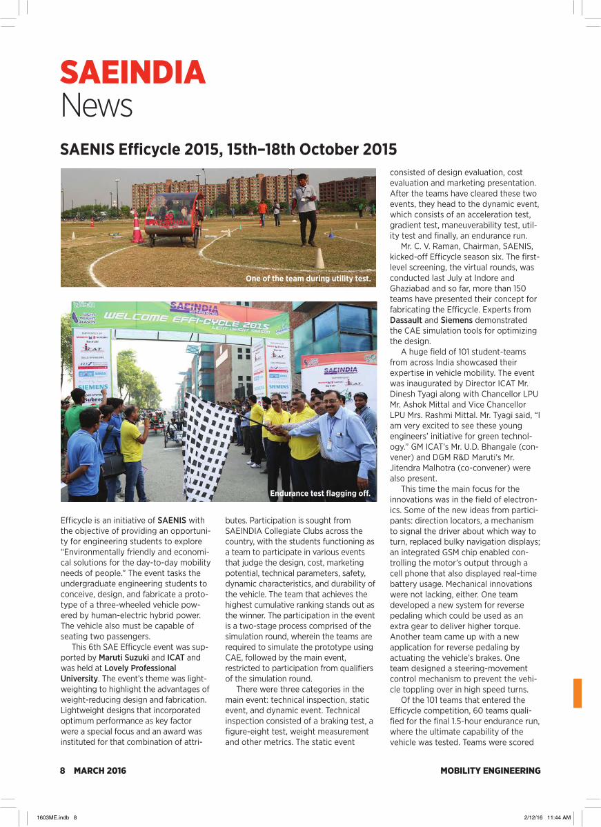
SAEINDIA NewsSAENIS Efficycle 2015, 15th–18th October 2015
Efficycle is an initiative of SAENIS with the objective of providing an opportuni-ty for engineering students to explore “Environmentally friendly and economi-cal solutions for the day-to-day mobility needs of people.” The event tasks the undergraduate engineering students to conceive, design, and fabricate a proto-type of a three-wheeled vehicle pow-ered by human-electric hybrid power. The vehicle also must be capable of seating two passengers.
This 6th SAE Efficycle event was sup-ported by Maruti Suzuki and ICAT and was held at Lovely Professional University. The event’s theme was light-weighting to highlight the advantages of weight-reducing design and fabrication. Lightweight designs that incorporated optimum performance as key factor were a special focus and an award was instituted for that combination of attri-
butes. Participation is sought from SAEINDIA Collegiate Clubs across the country, with the students functioning as a team to participate in various events that judge the design, cost, marketing potential, technical parameters, safety, dynamic characteristics, and durability of the vehicle. The team that achieves the highest cumulative ranking stands out as the winner. The participation in the event is a two-stage process comprised of the simulation round, wherein the teams are required to simulate the prototype using CAE, followed by the main event, restricted to participation from qualifiers of the simulation round.
There were three categories in the main event: technical inspection, static event, and dynamic event. Technical inspection consisted of a braking test, a figure-eight test, weight measurement and other metrics. The static event
consisted of design evaluation, cost evaluation and marketing presentation. After the teams have cleared these two events, they head to the dynamic event, which consists of an acceleration test, gradient test, maneuverability test, util-ity test and finally, an endurance run.
Mr. C. V. Raman, Chairman, SAENIS, kicked-off Efficycle season six. The first-level screening, the virtual rounds, was conducted last July at Indore and Ghaziabad and so far, more than 150 teams have presented their concept for fabricating the Efficycle. Experts from Dassault and Siemens demonstrated the CAE simulation tools for optimizing the design.
A huge field of 101 student-teams from across India showcased their expertise in vehicle mobility. The event was inaugurated by Director ICAT Mr. Dinesh Tyagi along with Chancellor LPU Mr. Ashok Mittal and Vice Chancellor LPU Mrs. Rashmi Mittal. Mr. Tyagi said, “I am very excited to see these young engineers’ initiative for green technol-ogy.” GM ICAT’s Mr. U.D. Bhangale (con-vener) and DGM R&D Maruti’s Mr. Jitendra Malhotra (co-convener) were also present.
This time the main focus for the innovations was in the field of electron-ics. Some of the new ideas from partici-pants: direction locators, a mechanism to signal the driver about which way to turn, replaced bulky navigation displays; an integrated GSM chip enabled con-trolling the motor’s output through a cell phone that also displayed real-time battery usage. Mechanical innovations were not lacking, either. One team developed a new system for reverse pedaling which could be used as an extra gear to deliver higher torque. Another team came up with a new application for reverse pedaling by actuating the vehicle’s brakes. One team designed a steering-movement control mechanism to prevent the vehi-cle toppling over in high speed turns.
Of the 101 teams that entered the Efficycle competition, 60 teams quali-fied for the final 1.5-hour endurance run, where the ultimate capability of the vehicle was tested. Teams were scored
One of the team during utility test.
Endurance test flagging off.
ISO 9001:2008Certified
rf/microwave instrumentation Other ar divisions: modular rf receiver systems ar europe
USA +1-215-723-8181.
www.arworld.usDownload the AR RF/Microwave Mobile App: www.arworld.us/arApp
Copyright © 2016 AR. The orange stripe on AR products is
Reg. U.S. Pat. & TM. Off.
Precision DSP ReceiverThis 18 GHz EMI receiver changes the way you think about emissions testing. Data is more accurate and test time is reduced.
1 to 2.5 GHz Solid State AmplifiersThe solid state alternative to TWTA’s. Improved harmonics, lower noise, superior linearity and reliability and now featuring 3,000 watts CW.
RF Conducted Immunity Test Systems Self-contained systems driven by our proprietary software; simplify calibration, testing, troubleshooting and reporting. They allow accurate, sensitive and repeatable measure-ment in one unit. Power levels to 150 watts and up to 3 GHz.
Multi-Tone TesterThis incredible system cuts RF Radiated Immunity testing from days down to hours by testing multiple frequencies simultaneously, from 10 kHz to 6 GHz, reducing product development cost and time to market.
Field Analyzer The new series of laser-powered electric field analyzers have an extremely high sample rate and can preciselymeasure pulsed electric fields in the microsecond range.
16,000 Watts of Pure PowerThe new 16000A225 amp. It covers 10 kHz to 225 MHz and delivers 16,000 watts of power and we’re not stopping there.Call us for power levels up to 50,000 watts.
Integrated Test SystemsAll-in-one test systems for any EMC application, DC to 50 GHz. Our systems make testing more efficient, accurate, and affordable.
0.7 to 18 GHz AmplifiersSolid State Class A CW Amplifiers up to 200 Watts from 0.7 – 6 GHz and 40 Watts from 4-18 GHz. Now you don’t have to settle for TWTAs.
Radiant Arrow® Bent Element AntennasWe bent the rules and advanced the science of log periodic antennas. Smaller, lighter, and more compact to fit in smaller chambers.
“W” Series AmplifiersThe most advanced, highest power and innovative RF Solid State amplifiers in the world. Now providing up to 4000 Watts CW from 80 to 1000 MHz.
family of products
www.arworld.us/EMCsource
In India, contact Complus Systems at www.complus.inor call 91-80-416-83883
Your Total EMC Source for Over 45 Years
ME AR Associated Ad 0316.qxp_Mobility FP 1/27/16 4:56 PM Page 1
1603ME.indb 8 2/12/16 11:44 AM

ISO 9001:2008Certified
rf/microwave instrumentation Other ar divisions: modular rf receiver systems ar europe
USA +1-215-723-8181.
www.arworld.usDownload the AR RF/Microwave Mobile App: www.arworld.us/arApp
Copyright © 2016 AR. The orange stripe on AR products is
Reg. U.S. Pat. & TM. Off.
Precision DSP ReceiverThis 18 GHz EMI receiver changes the way you think about emissions testing. Data is more accurate and test time is reduced.
1 to 2.5 GHz Solid State AmplifiersThe solid state alternative to TWTA’s. Improved harmonics, lower noise, superior linearity and reliability and now featuring 3,000 watts CW.
RF Conducted Immunity Test Systems Self-contained systems driven by our proprietary software; simplify calibration, testing, troubleshooting and reporting. They allow accurate, sensitive and repeatable measure-ment in one unit. Power levels to 150 watts and up to 3 GHz.
Multi-Tone TesterThis incredible system cuts RF Radiated Immunity testing from days down to hours by testing multiple frequencies simultaneously, from 10 kHz to 6 GHz, reducing product development cost and time to market.
Field Analyzer The new series of laser-powered electric field analyzers have an extremely high sample rate and can preciselymeasure pulsed electric fields in the microsecond range.
16,000 Watts of Pure PowerThe new 16000A225 amp. It covers 10 kHz to 225 MHz and delivers 16,000 watts of power and we’re not stopping there.Call us for power levels up to 50,000 watts.
Integrated Test SystemsAll-in-one test systems for any EMC application, DC to 50 GHz. Our systems make testing more efficient, accurate, and affordable.
0.7 to 18 GHz AmplifiersSolid State Class A CW Amplifiers up to 200 Watts from 0.7 – 6 GHz and 40 Watts from 4-18 GHz. Now you don’t have to settle for TWTAs.
Radiant Arrow® Bent Element AntennasWe bent the rules and advanced the science of log periodic antennas. Smaller, lighter, and more compact to fit in smaller chambers.
“W” Series AmplifiersThe most advanced, highest power and innovative RF Solid State amplifiers in the world. Now providing up to 4000 Watts CW from 80 to 1000 MHz.
family of products
www.arworld.us/EMCsource
In India, contact Complus Systems at www.complus.inor call 91-80-416-83883
Your Total EMC Source for Over 45 Years
ME AR Associated Ad 0316.qxp_Mobility FP 1/27/16 4:56 PM Page 1
1603ME.indb 9 2/12/16 11:44 AM

MOBILITY ENGINEERING10 MARCH 2016
SAEINDIA News
Inauguration of Division Offices, 13th October and November 2015,Chennai and MaduraiSAEINDIA Mahindra World City (MWC) Division was inaugu-rated on 13th October 2015 at Dr. Kalam Auditorium, Mahindra Research Valley. The session started with the traditional lamp lighting by Mr. N. Balasubramanian, Chairman, SAEISS.
During the inaugural function the dignitaries present were Dr. Aravind Bharadwaj, SAEINDIA President; Mr. N. Balasubramanian, Chairman, SAEISS; Mr. Jayanta Deb, Sr. VP, M&M; Mr. Velusamy, Sr. VP, M&M; and Mr. Sanjay Deshpande, Chief Engineer, M&M.
This division is headed by Mr. C. Pradeep, M&M as Chairman, Mr. R. Balasubramanian, M&M as Secretary, Mr. Baskara Sethupathy, SRM University as Treasurer, Mr. R. Senthilkumar, M&M as Vice Chair, and Mr. Thirumoorthy, Visteon as Vice Chair.
During this inaugural, the Member Management System (MMS), an online platform for SAEINDIA professional mem-bers, was relaunched and some of the dignitaries made their registration and renewal of membership with SAEINDIA.
SAEINDIA Madurai Division was inaugurated on 13 November 2015 at Kudil, TAFE, Madurai. The session started with the traditional lamp lighting by Dr. M. Uthayakumar, Kalasalingam University.
This division is headed by Mr. V. Srinivasan, TAFE, as chairman, Dr. R. Kannan, PSNA College of Engg. & Tech., as Secretary, and Dr. M. Uthayakumar, Kalasalingam University, as Treasurer. This inauguration also saw various representatives from TAFE.
based on the maximum number of laps completed during the allotted time.
Sant Longowal Institute of Engineering and Technology was declared overall winner of the event. College of Engineering, Pune and Guru
Mr. N. Balasubramanian, Chairman, SAEISS, lighting the ceremony of Mahindra World City (MWC) division inaugural.
Dr. M. Uthayakumar, Kalasalingam University, lighting the ceremony of Madurai division inaugural.
Overall winners of the event.
Nanak Dev Engineering College, Ludhiana were declared second- and third-place winners, respectively. Cash prizes worth Rs 5 Lakh and certificates were distributed to the winners of the various competitions.
Other winners were declared in cate-gories for best design, innovation, mar-keting presentation, acceleration, utility, gradient, maneuverability, durability, slogan, lightest vehicle, built-up quality, faculty advisor, and female participant.
Conveying best wishes to the win-ning teams, Executive Director (R&D) Maruti Suzuki India and Chairman SAENIS, Mr. C. V. Raman said, “The great battle for green mobility orga-nized by SAENIS at LPU in has exhibited new excitement and challenges as never before. I am enthralled to note the great efforts of young engineering students in accomplishing the targeted work for a ‘greener tomorrow.’ I truly appreciate the deep commitment and enthusiasm of each student for making the Efficycle-2015 a memorable and highly competitive event.” Executive Adviser (R&D) Mr. I. V. Rao and Vice President (R&D) Maruti Suzuki Dr. Tapan Sahoo also conveyed their congratulations to the winning teams.
ME Hindustan Ad 0316 ZZZZ.qxp_Mobility FP 1/29/16 10:04 AM Page 1
1603ME.indb 10 2/12/16 11:44 AM
ME Hindustan Ad 0316 ZZZZ.qxp_Mobility FP 1/29/16 10:04 AM Page 1
1603ME.indb 11 2/12/16 11:44 AM
MOBILITY ENGINEERING12 MARCH 2016
SAEINDIA News
AWIM Master Teacher Training Program 2015, 12th December 2015, Bangalore
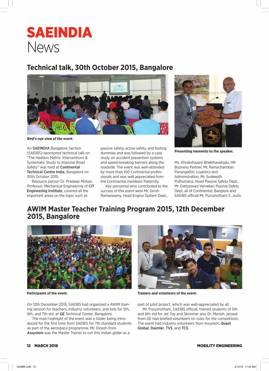
On 12th December 2015, SAEIBS had organized a AWIM train-ing session for teachers, industry volunteers, and kids for 5th, 6th, and 7th std. at GE Technical Center, Bangalore.
The main highlight of the event was a Glider being intro-duced for the first time from SAEBIS for 7th standard students as part of the aerospace programme. Mr. Dinesh from Assystem was the Master Trainer to run this Indian glider as a
part of pilot project, which was well-appreciated by all.Mr. Purushotham, SAEIBS official, trained students of 5th
and 6th std for Jet Toy and Skimmer also Dr. Manish Jaiswal from GE had briefed volunteers on rules for the competition. The event had industry volunteers from Assytem, Quest Global, Daimler, TVS, and TCS.
Technical talk, 30th October 2015, Bangalore
An SAEINDIA Bangalore Section (SAEIBS)-sponsored technical talk on “The Haddon Matrix: Interventions & Systematic Study to Improve Road Safety” was held at Continental Technical Centre India, Bangalore on 30th October 2015.
Resource person Dr. Pradeep Mohan, Professor, Mechanical Engineering of CIT Engineering Institute, covered all the important areas on the topic such as
passive safety, active safety, and testing dummies and was followed by a case study on accident prevention systems and speed-breaking barriers along the roadside. The event was well-attended by more than 100 Continental profes-sionals and was well appreciated from the Continental members fraternity.
Key personnel who contributed to the success of this event were Mr. Girish Ramaswamy, Head Engine System Dept.,
Bird’s-eye view of the event.
Presenting memento to the speaker.
Participants of the event. Trainers and volunteers of the event.
Ms. Dhrakshayani Bhakthavatsalu, HR Business Partner, Mr. Ramachandran Panangattiri, Logistics and Administration, Mr. Sudeepth Puthumana, Head Passive Safety Dept., Mr. Dattprasad Vernekar, Passive Safety Dept, all of Continental, Banglore and SAEIBS official Mr. Purushotham S. Joshi.
1603ME.indb 12 2/12/16 11:44 AM

MOBILITY ENGINEERING MARCH 2016 13
SAEINDIA News
AWIM Regional Olympics 5th December 2015, Pune
SAEINDIA Western Section, in association with Automotive Research Association of India (ARAI), Eaton Technologies, John Deere, Cummins India and DC Design conducted “A World In Motion (AWIM) Pune Olympics 2015 at The Orchid School, Baner, Pune on 5th December 2015.”
This competition saw school students work as a team, applying scientific design concepts and exploring the principles of laws of motion, inertia, force, momentum,
friction, air resistance, jet propulsion, etc. to create moving vehicles like skimmer and balloon-powered jet-toy cars. The competition was judged by a panel of eminent personalities from the automo-tive and art fields in and around Pune.
The contest, full of fun and chal-lenges for school students called A World In Motion (AWIM), had two main ingredients in this innovative, hands-on, physical science curriculum, designed
by the Society of Automotive Engineers (SAE) USA. AWIM was started in the USA, with India the second country to conduct the competition at national level for school children.
AWIM National Olympics 2015 was scheduled at Mahindra Research Valley, Chennai, on 23rd January, 2016. The win-ning team from AWIM Pune Olympics for the “Jet Toy” and “Skimmer” participated in the competition.
Jet-Toy (6th Std.) winner: Panditrao Agashe School, Pune.
Lamp lighting ceremony, from left: Mr. Richard Vreeland, Mr. Sreekumar Panicker, Mr. Vinod Patel, Mr. Pramod Patil, Mr. Yatin Jayawant, Ms. Swapna Kelkar, Mr. B.V. Shasundara.
Mr. Abraham Joseph, CTO, Bajaj Auto Ltd., addressing the participants during valedectory.
Skimmer (5th Std.) Millennium National School, Pune.
JET-TOY (6TH STANDARD)S. NO. CATEGORY NAME OF THE SCHOOL
1 Overall Winner J34 - Panditrao Agashe School 2 Overall Runners-up J24 - Shriram Vidya Mandir, Bhosari 3 Distance J34 - Panditrao Agashe School J4 - SNBP School 4 Weight J13 - Moledina School 5 Accuracy J15 - Millennium National School 6 Speed J11 - New English School, Sasane Nagar J29 - PMC School 152 B, Balewadi J33 - Panditrao Agashe School 7 Time J7 - Mother Teresa High School, Kharadi 8 Presentation J9 – New English School, Ramanbag
WINNING TEAMSSKIMMER (5TH STANDARD)
S. NO. CATEGORY NAME OF THE SCHOOL 1 Overall Winner S 17 - Millennium National School, Karve Nagar 2 Overall Runners-up S2 - Ramchandra Gaikwad School, Dighi 3 Distance S21 - PMC School No. 152 B, Balewadi 4 Weight S7 - Mother Teresa High School, Kharadi 5 Accuracy S16 - Moledina School S20 - The Orchid School 6 Speed S18 - Karntiveer Vasudev Balwant Phadake School 7 Turnability S17 - Millennium National School, Karve Nagar 8 Presentation S13 – New English School, Sasane Nagar
1603ME.indb 13 2/12/16 11:44 AM

MOBILITY ENGINEERING14 MARCH 2016
SAEINDIA NewsLecture Meeting, 19th December 2015, Chennai
SINE 2015, 13th-24th December 2015, Pune
The first lecture meeting program on ‘‘Latest Trends in Brake System Developments” was organized by SAEINDIA Mahindra World City (MWC) Division on 19th December 2015 at ESB Seminar hall, SRM University, Chennai. The speakers of the event were Mr. S Raghupathi (M&M) and Mr. Vallabha Rao (M&M) Chennai.
Mr. C. Pradeep, Chairman, SAEISS MWC Division, inaugurated the lecture meeting in the traditional way of lighting
the kuthu vilaku. Mr. P. Baskara Sethupathi, Treasurer, SAEISS MWC Division, gave the welcome address.
The speakers of the event were Mr. S Raghupathi (M&M) and Mr. Vallabha Rao (M&M); Chennai began the speech on the topic. The entire session went well with precise information, presen-tation, knowledge-sharing and thoughts about the future and new technologies.
Being the first lecture meeting, the
participants also suggested various top-ics for similar future lecture sessions. Mr. N. Balasubramanian, Chairman, SAEISS gave some suggestions to the members regarding this topic and interacted with them. Mr. C. Pradeep explained about the purpose of the lecture meeting and future activities of the division.
The session came to an end with the presentation of a momento to the chief guest, Mr. S. Raghupathi (M&M), by Mr. N. Balasubramanian, Chairman, SAEISS.
Students INdustry Education (SINE) 2015 was held during December 2015 by the SAEINDIA Off-highway Board. The pro-gram is aimed at providing awareness of off-highway industry and technologies to students from engineering institutes around the country. Maintaining the importance of diversity, in the past two programs the participants’ focus has been on female students. Through a rigorous pre-defined process and with the help of a competent panel, 25 female engineering students from various colleges from eight different states across India were selected for this program.
It was yet another historic day for the off-highway board for all participants, who travelled to Pune with excitement, anxiety, and eagerness for the event. College of Engineering (COE) Pune sponsored arrangements for the participants at the Girls Hostel in Pune. The Inauguration of SINE 2015 was held at John Deere Technology Center at Pune in the presence of Mr. Nitin Agarwal, Chairman, SAEINDIA Off-Highway Board and Head, Asia Technology Innovation Center John Deere India, Mr. Anil Gupta, Convener for the SINE 2015, Dr. K. C. Vora, Vice President, SAEINDIA and Sr. Dy. Director & Head, ARAI Academy, and other SAEINDIA leadership members. The keynote was delivered by the chief guest, Ms. Alka Pande, Advisor at the Automotive Skills Development Council, along with addresses by other dignitaries from the industry and aca-demia. Three participants attending the first SINE 2013 now are working with the off-highway industries.
Speaking about the program at the inauguration, Mr. Nitin
Agarwal mentioned that SINE 2015 is a focused program to pro-mote gender diversity in the off-highway industries, explaining that the female students—selected from various engineering institutes—were scheduled to participate in the program for nearly two weeks. The program is targeted toward creating awareness of the technology advances and the inclusive work environment offered by this sector. The program provides an opportunity to experience the work environment in the manu-facturing factory floor, technology centers, simulation labs, test-ing and certification setups and so forth. Apart from technical
Mr. C. Pradeep, Chairman, Mahindra World City Division, giving the inaugural address.
Mr. N. Balasurbramanian, Chair, SAEISS, presenting memento to the chief guest, Mr. S. Raghupathi, M&M.
Inaugural of SINE 2015 lamp lighting by dignitaries.
1603ME.indb 14 2/12/16 11:44 AM

MOBILITY ENGINEERING MARCH 2016 15
SAEINDIA News
and behavioural training sessions, the students enjoy interaction with leaders from the industry. These interactions will help pro-vide perspective for the future of the sector in the backdrop of the changing techno-economic environment, with the focus on the infrastructure and agriculture sectors’ growth in the country. SINE 2015 also is a reflection of the commitment of SAEINDIA toward gender diversity and industry-academia relationship.
Participants underwent two weeks of extensive learning through product awareness, technology training, leadership interactions, interactive sessions, and industry and institutes visits at companies including Ansys, ARAI, Caterpillar, Cummins, Eaton, John Deere, PTC, and Varroc. Various ses-sions covered technologies such as hydraulics, machining, electronics, sensors, software, IoT, augmented reality, etc. They also learned functional approaches to quality, innovation, man-ufacturing, product development and testing. The industry shop-floor visits provided insight on the state-of-the-art man-ufacturing facilities and the technologies that help convert digital drawings into products and were provided a first-hand view of the professional environment in these industries.
The technology center visits provided insight on the advanced technology being used in the off-road sector to design and validate a multitude of products and the simula-tion and virtual reality environment that supports the industry at different phases of product development. The participants could witness the advance capabilities and the technologies the industry currently offers and get glimpses of the future of the sector. The visit to ARAI also provided insight on the advance capabilities it has for testing of the vehicles.
Mr. Anil Gupta, SAEINDIA Off-highway Board Member, Convener, SINE 2015 and Head, Hydraulics Engineering, Eaton India Engineering Center, said, “Over the years, SINE became a well-known event among the institutions and a brand for the SAEINDIA off-highway board. This not only provided a great plat-form for women engineering students to learn about off-highway industry, it ignited a passion for engineering and to create a dif-ference for community. Not only the participating students but associated industries also hugely benefited as the students bring in fresh perspective and energy during the interactions.”
The Valedictory function was at College of Engineering Pune on 24th December 2015 and was graced by the Chief
Guest Dr. Prashanth Ravi, Head Engineering Engine division, Caterpillar, and Guest of Honor was Dr. B. B. Ahuja, Director, COE, Pune. The session also was attended by the leadership from SAEINDIA and industry representatives. It was an emo-tional movement for all the participants, as well as the indus-try and academia representatives who interacted with the participants during the event. Listening to the participants’ experiences, the organising team was gratified about the steps the program has taken toward achieving its objectives.
The participants left with new awareness and knowledge about the off-highway sector. Apart from the technical learning and experience, they also were connected with fellow partici-pants and the industry-academia members. With the efforts of SAEINDIA Off-highway Board, the industry can look forward to seeing these young women potentially lead some of the affili-ated companies, while for now, the young engineers completed the program with added confidence and pride.
SINE 2013 participants sharing their experiences during the inaugural of SINE 2015.
Team SINE 2015 during inaugural function.
Dignitaries initiating the valedectory function by lamp lighting.
Participants sharing the
key learnings of the event.
1603ME.indb 15 2/12/16 11:44 AM

MOBILITY ENGINEERING16 MARCH 2016
SAEINDIA NewsAWIM Regional Olympics, 19th and 30th December 2015, Tirunelveli and ChennaiThe 8th AWIM Regional Olympics was held in two phases, the first at Tirunelveli and the second phase at Chennai. The first phase was held at St. John Higher Secondary School, PalayamKottai, Tirunelveli on 19th December 2015. The program was inau-gurated by Mr. Selvanayagam from CEO Office-Tirunelveli District.
Mr. Nandhan, SAEISS member, explained the program agenda to all students and teachers and the students
started constructing their jet toys from the kits distributed to them. The com-petition encompassed five performance tests: distance, time, speed, payload and presentation, with each test having 3 trials per team.
The second phase of the event was held at Crescent School, Chennai on 30th December 2015. The program was inaugurated by Mr. S. Yoosuf, Senior Principal of Crescent School, Dr. R. Rajendran, Professor of B.S. Abdur
Rahman University, and Mr. B. Kumaran, AWIM Champion, SAEISS and Mr. G. Vijayan, Deputy Director General, SAEINDIA, presided over the valedic-tory function.
This competition saw students work as a team to apply scientific design con-cepts and explore the principles of laws of motion, inertia, force, momentum, friction, air resistance and jet propulsion to create moving vehicles like the bal-loon-powered jet-toy.
SCHOOLS AWARDED UNDER EACHCATEGORY IN REGIONAL OLYMPICS
S. NO. CATEGORY SCHOOL NAME 1 Distance Devi Academy 2 Time Good Will Matric School 3 Speed SSM Academy 4 Weight SKV International School 5 Accuracy P S Senior Sec. School
Mr. Nandhan explaining the agenda at Tirunelveli.
One of the team during their presentation at Tirunelveli.
One of the teams during construction phase at Chennai.
One of the teams during prize distribution at Chennai.
THE WINNING AWIM TEAMS FROMSAEINDIA SOUTHERN SECTION
(Next participate in the National Olympics)S. NO. SCHOOL NAME 1 Amirta Vidyalayam 2 Maharishi Vidhya Mandhir 3 Devi Academy 4 SSM Matriculation 5 G.H.S.S., Maranthai 6 Avvaiyar G.G.Hr.Sec.School, Pavoorchatram
1603ME.indb 16 2/12/16 11:44 AM

MOBILITY ENGINEERING MARCH 2016 17
Industry NEWS
Tech Mahindra buys controlling stake in PininfarinaTech Mahindra Ltd. and Mahindra & Mahindra (M&M) have jointly entered into an agreement with Pincar S.r.l. to purchase a controlling stake in Pininfarina S.p.A., an Italian brand in auto-motive and industrial design. The move will give Tech Mahindra access to European companies with which Pininfarina has close ties, such as Ferrari, Alfa Romeo, Maserati, and Peugeot, and the opportunity for Tech Mahindra to influence product con-ceptualization, and design and styling. Pininfarina will gain “a newly heightened scale to its operations” due to Tech Mahindra’s presence in 90 countries and access to about 780 customers. As part of the agreement, Tech Mahindra and M&M will purchase 76.06% of Pininfarina shares from Pincar at a price of Euro 1.1 per share. The investment is via a joint venture company, held 60% by Tech Mahindra and 40% by M&M. Pininfarina will continue to remain an independent company, with Paolo Pininfarina continuing as the Chairman of its board.
“Pininfarina will add enormous value to Tech Mahindra’s portfolio of engineering services,” Anand Mahindra, Chairman of the Mahindra Group, said in a statement announcing the agreement. “But just as important is the fact that the legend-ary high-end design credentials of Pininfarina will significantly enhance the design capabilities of the entire Mahindra Group.”
Rockwell Collins expands India operations Rockwell Collins recently opened a new, expanded facility in Bangalore, India, that bolsters the company’s presence in the country. The company has signed a 15-year lease for the Bangalore building, which will initially house 30 employees but is expected to reach 100 employees after one year of op-eration. Rockwell Collins continues to expand in India as the country’s growing economy and aerospace industry presents new opportunities for the company.
HydraForce strengthens electrohydraulic-controls position in IndiaHydraForce, a manufacturer of hydraulic cartridge valves, manifolds, and electrohydraulic controls, has established a new LLC corporation in India. HydraForce India LLC, which will be based in the Vatika Business Center in Pune, Maharashtra, will support sales and engineering activities on
Pininfarina is a styling company known for its designs with car brands including Ferrari and Alfa Romeo. Pictured is the Ferrari Sergio concept car designed by Pininfarina.
Rockwell Collins’ expansion in India is a reflection of the increasing demand for services from its India Design Center in Hyderabad, which is focused on the design of display applications for commercial and military customers and Flight Management Systems.
“Adding Pininfarina’s legendary design skills to our Integrated Engineering Solutions enables a strong entry into automotive styl-ing, design, and development and reinforces our body engineer-ing capabilities,” added CP Gurnani, CEO and Managing Director, Tech Mahindra. “Further, Pininfarina’s 25-year design expertise in industries beyond automotive will give us [an] edge in areas such as aerospace, consumer electronics, architecture and interiors, and transportation where we already have a strong footprint.”
“The opening is a reflection of our commitment to India, as well as the increasing demand for services from our India Design Center (IDC) in Hyderabad,” said Sunil Raina, Managing Director of Rockwell Collins India. “We chose Bangalore because of the high concentration of engineering talent there and the fact that it is an aerospace hub.”
Rockwell Collins’ design center in Hyderabad augments the company’s existing engineering and information technology capabilities. The IDC was created to help the company expand its global footprint, meet the needs of customers in the region, and increase access to high-quality technical talent. The IDC is dedicated to product development for global markets, with ini-tial work focused on the design of display applications for com-mercial and military customers and Flight Management Systems. The design center currently has 630 employees, and the company plans to continue to grow the facility.
Rockwell Collins’ facility in Gurgaon, Haryana, near New Delhi, houses the business development, program manage-ment, systems engineering, and related support activities for net-enabled communications, navigation, surveillance, displays, sensors, simulation and training, and integrated systems and subsystems for airborne, ground, and maritime applications.
1603ME.indb 17 2/12/16 11:44 AM

MOBILITY ENGINEERING18 MARCH 2016
Industry NEWS
Magneti Marelli opens plant to produce automated manualsMagneti Marelli, through its Magneti Marelli Powertrain India Private Ltd. joint venture with Maruti Suzuki and Suzuki Motor Co., recently inaugurated a new industrial site for the production
Volvo launches first hybrid buses in IndiaThe first Volvo hybrid city bus pilot will start in the first half of 2016 in Navi Mumbai with Navi Mumbai Municipal Transport. To promote environmentally friendly vehicles, the Indian government has recently launched the FAME India (Faster Adoption and Manufacturing of
HydraForce India will support the advancing development of technology on off-highway equipment in India, specifically in the area of electrohydraulic control systems. Pictured is a manifold block equipped with proportional pressure control valves and a programmable electronic valve driver suitable for transmission controls, including power shuttle and power shift functions.
Magneti Marelli’s new facility near New Delhi will have a production capacity of 280,000 robotized gearbox kits per year.
Volvo is bringing its hybrid bus technology to India in the first half of 2016, promising a fuel-consumption benefit of 39% compared to diesel.
behalf of all HydraForce facilities and systems developers in India. HydraForce also maintains business relationships with a Global System Integrator manu-facturing partner in India—Dantal Hydraulics Pvt. Ltd. in Haryana—and fluid power distributor ServoControls & Hydraulics India Pvt. Ltd. in Karnataka.
“As India works to develop and strengthen its infrastructure—roads and highways, bridges, ports and airports—demand for locally produced construction and agricultural equipment is expected to increase,” explained Mark Wilson, HydraForce Sales Director. “Our LLC cor-poration will support the rapidly advanc-ing development of technology on off-highway equipment in India. It also will help HydraForce demonstrate a lead-ership position in our technology seg-ment of electrohydraulic control systems.”
HydraForce claims to have created thousands of custom control solutions for a variety of off-highway industries, including farming, construction, marine, material handling, mining, and forestry.
of automated manual transmissions (AMTs) for automobiles. The plant is located in Manesar, near New Delhi, in the same area where the company pro-duces powertrain electronic control units (ECUs). The new 7500-m² (80,700-ft²) facility houses the produc-tion lines and offices, and will employ approximately 115 people when fully operational. It will have a production capacity of 280,000 robotized gearbox kits per year. Magneti Marelli says the facility was built to address the growing market success of AMTs in India over the past two years and to meet the de-mand from local automakers for future implementations. The Maruti Celerio, Maruti Alto, Tata Nano, and Tata Zest are examples of cars already equipped with the company’s AMT.
The technology is based on the use of an ECU combined with an electrohydraulic system that controls the use of the clutch when changing gears, allowing the driver to shift gears without the use of the clutch, either sequentially or in a fully automatic way. The electronic optimiza-tion of the ATM gearbox results in reduced fuel consumption and CO2 emissions com-pared to standard automatic and manual transmissions, the company claims.
Hybrid and Electric vehicles in India) program, offering incentives on electric and hybrid vehicles. The Volvo hybrids will be manufactured in the company’s facility in Bangalore.
“Hybrid buses are an important solu-tion for cities that want to reduce vehi-cle emissions. I am very proud that Volvo is the first bus manufacturer to introduce hybrid buses in India,” Håkan Agnevall, President Volvo Buses, said in a statement.
“The unveiling of the first Volvo hybrid city bus in India is contextual given the impetus from the central gov-ernment to popularize public transport, while supporting the adoption of clean technology. Volvo has played a key role in redefining urban commute for mil-lions of passengers in Indian cities. Now, with the Volvo hybrid city bus we are confident of transforming the public transport landscape further, by inspiring more cities to adopt this solution,” said Akash Passey, Senior Vice President, Region International, Volvo Buses.
Volvo says that its hybrids offer a fuel consumption that is up to 39% lower than that of conventional diesel buses, which cuts CO2 emissions by the same amount and nitrogen oxides and particles by 50%. Volvo’s electric hybrids, which offer fuel savings of 75%, are currently running in regular traffic in the European cities of Gothenburg, Stockholm, and Hamburg.
1603ME.indb 18 2/12/16 11:44 AM

MOBILITY ENGINEERING MARCH 2016 19
TECHNOLOGYReport
AUTOMOTIVE POWERTRAIN
Low-friction techniques push advanced city-car project toward 84-mpg target
In the beginning there were Shell, Gordon Murray Design (GMD), Geo Technology, and an idea.
The idea was to create a very small gasoline engine that demonstrated super efficiency to provide a 3-seat, aerodynamic, lightweight and ultra-compact city car having forward opening single canopy access with zero-width swing. The car would have a combined fuel consumption of 2.8 L/100 km (84 mpg equivalent) or less, and a top speed of around 130 km/h (80 mph).
To achieve it, in April 2015 Project M (for mobility) was initiated and the part-ners agreed: “Let progress commence.”
It did, with R&D development of the Gordon Murray T25M. Now, as the proj-ect continues, the cloak of confidential-ity has been partially pulled aside. At Shell’s Hamburg [Germany] Technical Center, senior executives of the compa-nies involved revealed the shape of graphs to come.
Bob Mainwaring, Shell Lubricants Technology Manager for Innovation, said: “Shell supplied lubricants for Gordon Murray Design’s T25 city car program (http://articles.sae.org/10006/) in 2010,
with the result that fuel consumption improved by 6.5% in the European urban cycle and 4.7% in the combined cycle. Those results seeded the thinking that with energy consumption set to double by 2050, what would be the result if we worked together on an holistic, co-engi-neered approach with a new engine design to achieve a very high level of engine efficiency?”
The answer is emerging, with a major advance centering on reducing the friction of almost all moving parts of that engine using advanced lubrica-tion solutions complemented by exten-sive use of diamond-like carbon (DLC) coatings.
Mainwaring emphasized the need for companies to collaborate and to link hardware design with programs to reduce friction. That is well enough known but achieving it can be tough, he acknowledged.
“On one hand we want to reduce vis-cosity to lower drag forces and lower friction but on the other hand reducing viscosity, oil thicknesses within a com-ponent are likely to drop, making the hardware more vulnerable to wear,” he noted. “Balancing the two is very
important and we call that being ‘close to the edge but safe’.”
“Safe” in this context means push-ing the limits of viscosity while achiev-ing acceptable wear. Shell engineers adjusted the lubricant’s formulation to give as low viscosity as possible at low temperature, while keeping it as high as it needs to be (which might be a low value at high temperature) to stop sur-faces touching and wearing, he said, noting critical interfaces such as the cam-to-tappet and piston ring-to-cyl-inder liner.
By coating these surfaces with DLC, the Shell team was able to protect these and ensure that the lubricant-vs.-wear pinch point is the crankshaft and its journal bearings.
That pinch-point is in the control of the viscosity of the lubricant and the additives, Mainwaring explained, adding a simple summation: How low can the viscosity be for the loads that are imposed on the crankshaft?
An essential element of achieving this balance is to consider the lubricant as a design component: “Changing the hardware to match the lubricant and the lubricant to match the hardware will
The piston is the particular focus for attention to improve engine efficiency, explained Geo Technology’s Hidehito Ikebe.
Shell’s Bob Mainwaring emphasizes the importance of inter-company collaboration to achieve enhanced engine efficiency for the T25M project.
1603ME.indb 19 2/12/16 11:44 AM

MOBILITY ENGINEERING20 MARCH 2016
give the best fuel economy,” he told Automotive Engineering.
The prototype formulation for Project M is in the SAE 0W-12 range compared to the typical 5W-30 grade. Industry specifications do not recog-nize either 0W-12 or thicker 0W-16. In working with Geo Technology to co-engineer the engine and its oil, Shell engineers are essentially throw-ing away the specification book and the compromises it forces. Their aim instead is to design an engine oil that delivers the very low friction results that it is targeting. Use of friction mod-ifiers, some containing elements such as molybdenum will be used.
It is this bespoke approach that has been applied to the base 660-cm3 Mitsubishi 3-cylinder engine that will power the one-off technology demon-strator T25M. The base engine is high revving and powerful (55 kW/73-hp at 7500 rpm) for its size, but Hidehito Ikebe, Director of Engineering at Geo
Technology, said that to support the project’s criteria, this has been reduced to 36 kW (48 hp) at 5500 rpm. Compression ratio was raised from 10.8:1 to 12.4:1.
The company has designed some new parts, introduced “beehive” type valve springs, titanium valves, and incorporated DLC solutions to reduce friction in several areas.
Ikebe said the piston is the most significant area for reducing friction. Except for the crown, piston design for the T25M is all new. Two rings instead of the normal three are used, and the number of strakes reduced by 40%. The connecting rods were extended by 9%, and piston weight reduced by 40%. Collectively these changes pro-duce a 30% reduction in inertial mass, he explained.
There is no intention at present of bringing the T25M to market. Project M is a capability analysis exercise only, but all those involved in it clearly hope that it will represent a building block for future advances in efficiency for series produced engines. Certainly some “insights of value” have emerged, agree the participants.
The project is being funded by Shell, although no specific details
of its budget have been released. The timing of getting the
T25M to its unveiling stage (moved from an officially announced November 2015
to Q2 of 2016) is due both to the project being “very ambitious” and for the decision to first gather all the data needed and
compare it against three vehicle archetypes on an energy
and fuel consumption basis. Aerodynamics and materials also are
a significant part of Project M. With regard to aerodynamic efficiency, it might be thought that it is not of para-mount importance for a city car. But Andy Jones, GMD’s Design Director, emphasized that for a car carrying three, 95th-percentile adults, its sub-0,30 Cd figure is good. The vehicle is relatively high at 1.6 m/5.2 ft, but very short for “nose-in” parking at 2.65-m long and 1.35-m wide (8.7 x 4.4 ft) to permit three of the type to park in a standard parking space.
Achieving the relatively low Cd is significant, Jones explained, because city cars are often driven not just in cen-tral areas but into and around urban areas where speeds reached can be rel-atively high. The car’s designated 128 km/h (80 mph) Vmax capability makes aerodynamics significant.
Jones said that application of advanced materials and rethink of the vehicle’s primary structure is the second major element of the T25M’s “fight to reduce vehicle drive energy,” with a lightweighting philosophy “that goes beyond conventional architectures.”
The T25M contains the materials evo-lution that has led to GMD’s iStream Carbon, shown for the first time at the 2015 Tokyo Motor Show. It is the chassis technology used for the Yamaha Sports Ride Concept.
Stuart Birch
One aspect of how increased efficiency is being achieved for the T25M project.
Left to right: Bob Mainwaring, Shell; Andy Jones, GMD; and Hidehito Ikebe, Geo Technology, are working together to create the T25M.
The 660-cc Mitsubishi engine for the Gordon Murray Design T25M is subject to extensive development and testing.
TECHNOLOGY Report
1603ME.indb 20 2/12/16 11:44 AM
MOBILITY ENGINEERING MARCH 2016 21
OFF-HIGHWAY PROPULSION
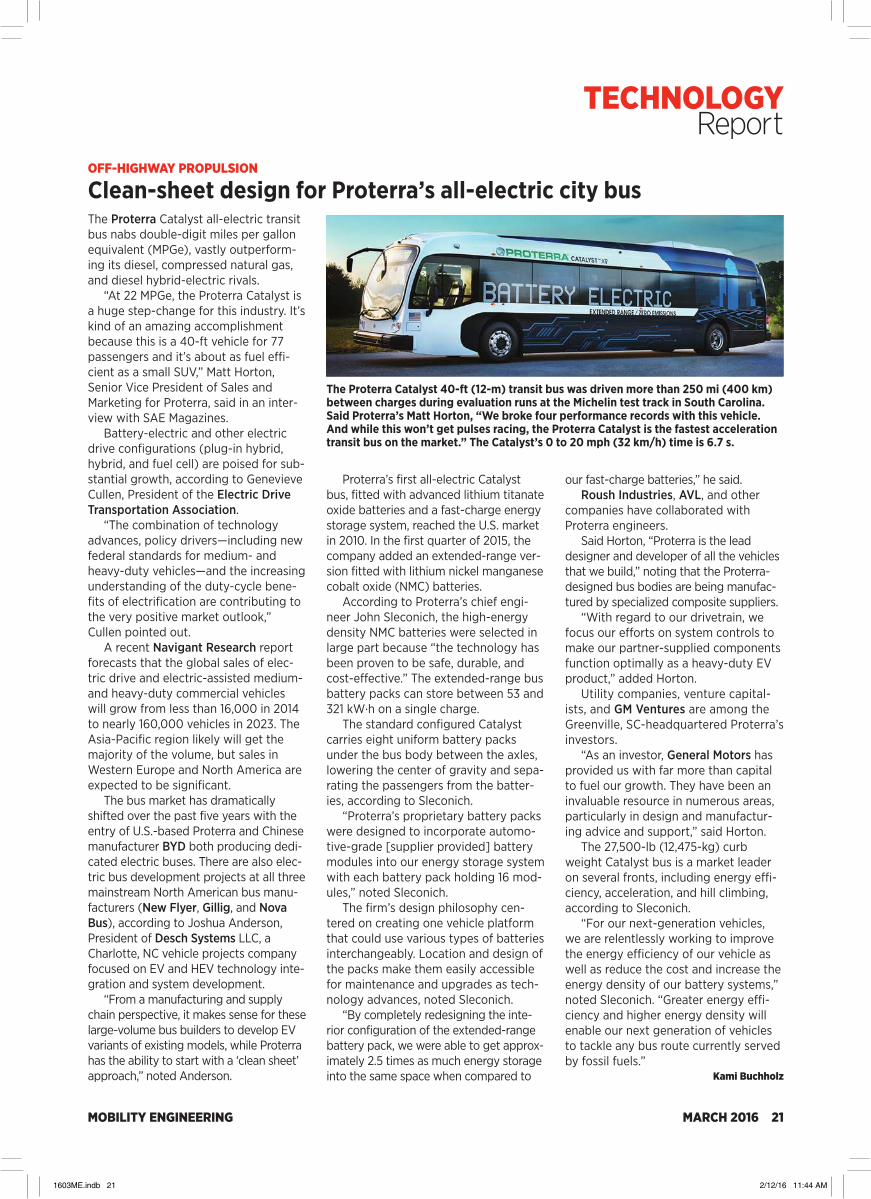
Clean-sheet design for Proterra’s all-electric city busThe Proterra Catalyst all-electric transit bus nabs double-digit miles per gallon equivalent (MPGe), vastly outperform-ing its diesel, compressed natural gas, and diesel hybrid-electric rivals.
“At 22 MPGe, the Proterra Catalyst is a huge step-change for this industry. It’s kind of an amazing accomplishment because this is a 40-ft vehicle for 77 passengers and it’s about as fuel effi-cient as a small SUV,” Matt Horton, Senior Vice President of Sales and Marketing for Proterra, said in an inter-view with SAE Magazines.
Battery-electric and other electric drive configurations (plug-in hybrid, hybrid, and fuel cell) are poised for sub-stantial growth, according to Genevieve Cullen, President of the Electric Drive Transportation Association.
“The combination of technology advances, policy drivers—including new federal standards for medium- and heavy-duty vehicles—and the increasing understanding of the duty-cycle bene-fits of electrification are contributing to the very positive market outlook,” Cullen pointed out.
A recent Navigant Research report forecasts that the global sales of elec-tric drive and electric-assisted medium- and heavy-duty commercial vehicles will grow from less than 16,000 in 2014 to nearly 160,000 vehicles in 2023. The Asia-Pacific region likely will get the majority of the volume, but sales in Western Europe and North America are expected to be significant.
The bus market has dramatically shifted over the past five years with the entry of U.S.-based Proterra and Chinese manufacturer BYD both producing dedi-cated electric buses. There are also elec-tric bus development projects at all three mainstream North American bus manu-facturers (New Flyer, Gillig, and Nova Bus), according to Joshua Anderson, President of Desch Systems LLC, a Charlotte, NC vehicle projects company focused on EV and HEV technology inte-gration and system development.
“From a manufacturing and supply chain perspective, it makes sense for these large-volume bus builders to develop EV variants of existing models, while Proterra has the ability to start with a ‘clean sheet’ approach,” noted Anderson.
Proterra’s first all-electric Catalyst bus, fitted with advanced lithium titanate oxide batteries and a fast-charge energy storage system, reached the U.S. market in 2010. In the first quarter of 2015, the company added an extended-range ver-sion fitted with lithium nickel manganese cobalt oxide (NMC) batteries.
According to Proterra’s chief engi-neer John Sleconich, the high-energy density NMC batteries were selected in large part because “the technology has been proven to be safe, durable, and cost-effective.” The extended-range bus battery packs can store between 53 and 321 kW·h on a single charge.
The standard configured Catalyst carries eight uniform battery packs under the bus body between the axles, lowering the center of gravity and sepa-rating the passengers from the batter-ies, according to Sleconich.
“Proterra’s proprietary battery packs were designed to incorporate automo-tive-grade [supplier provided] battery modules into our energy storage system with each battery pack holding 16 mod-ules,” noted Sleconich.
The firm’s design philosophy cen-tered on creating one vehicle platform that could use various types of batteries interchangeably. Location and design of the packs make them easily accessible for maintenance and upgrades as tech-nology advances, noted Sleconich.
“By completely redesigning the inte-rior configuration of the extended-range battery pack, we were able to get approx-imately 2.5 times as much energy storage into the same space when compared to
our fast-charge batteries,” he said.Roush Industries, AVL, and other
companies have collaborated with Proterra engineers.
Said Horton, “Proterra is the lead designer and developer of all the vehicles that we build,” noting that the Proterra-designed bus bodies are being manufac-tured by specialized composite suppliers.
“With regard to our drivetrain, we focus our efforts on system controls to make our partner-supplied components function optimally as a heavy-duty EV product,” added Horton.
Utility companies, venture capital-ists, and GM Ventures are among the Greenville, SC-headquartered Proterra’s investors.
“As an investor, General Motors has provided us with far more than capital to fuel our growth. They have been an invaluable resource in numerous areas, particularly in design and manufactur-ing advice and support,” said Horton.
The 27,500-lb (12,475-kg) curb weight Catalyst bus is a market leader on several fronts, including energy effi-ciency, acceleration, and hill climbing, according to Sleconich.
“For our next-generation vehicles, we are relentlessly working to improve the energy efficiency of our vehicle as well as reduce the cost and increase the energy density of our battery systems,” noted Sleconich. “Greater energy effi-ciency and higher energy density will enable our next generation of vehicles to tackle any bus route currently served by fossil fuels.”
Kami Buchholz
The Proterra Catalyst 40-ft (12-m) transit bus was driven more than 250 mi (400 km) between charges during evaluation runs at the Michelin test track in South Carolina. Said Proterra’s Matt Horton, “We broke four performance records with this vehicle. And while this won’t get pulses racing, the Proterra Catalyst is the fastest acceleration transit bus on the market.” The Catalyst’s 0 to 20 mph (32 km/h) time is 6.7 s.
TECHNOLOGY Report
1603ME.indb 21 2/12/16 11:44 AM

MOBILITY ENGINEERING22 MARCH 2016
AEROSPACE PROPULSION
GE’s clean-sheet turboprop engine to launch with Textron AviationTextron Aviation has opted for GE Aviation’s all-new turboprop engine to power its single engine turboprop (SETP). The 1300 shaft horsepower (SHP)-rated turboprop engine will be the first entry in GE’s new family of tur-boprop engines designed specifically for business and general aviation air-craft in the 850- to 1600-SHP range.
Brad Mottier, Vice President and General Manager of GE Aviation’s Business & General Aviation and Integrated Systems division, said during the recent announcement that “this new engine features an industry-best 16:1 overall pressure ratio (OPR), enabling the engine to achieve up to 20% less fuel consumption and 10% more cruise power compared to competitor offer-ings in the same size class, which usu-ally feature an OPR of 9:1. It also has 4000-6000 hour MTBO,” or mean time between overhauls, which is about 30% longer than with existing engines.
As an advantage of being part of GE, says Mottier, “We don’t have to pay for research, we just go to the GE store for proven technologies from GE’s large commercial and military engines and props. For example, we didn’t have to pay hundreds of millions of dollars into research for stator vanes.”
Other new design and manufacturing technologies leveraged from GE’s latest military and commercial engines include an all-titanium, 3D aero compressor design for lightweight and efficient power generation and additive manu-facturing capabilities pioneered for the CFM LEAP turbofan.
“For the past five years, GE conducted design studies and actively researched the turboprop market to identify and integrate the best of our next-gen com-mercial and military technologies at the lowest cost and risk to our business avia-tion customers,” said Mottier. “Our mis-sion is to make the operation of this engine look just like a jet.”
“Our SETP will combine the best of both clean-sheet aircraft and new engine designs,” said Christi Tannahill, Senior Vice President, Turboprops and Interior Design at Textron Aviation. “We expect it to outperform the competition in critical areas ranging from cabin size and acquisition cost to performance
capability and fuel savings.”Textron Aviation’s new aircraft is
expected to have a range of more than 1500 nmi and speeds higher than 280 knot. Part of the enablers to those sta-tistics are key features of the new tur-boprop engine that include a ruggedized, modular architecture based on the T700/CT7 turboshaft, and cooled turbine blades that enable higher thrust and fuel efficiency, also leveraged via technology from the T700/CT7. In the latter case, multi-stage turbines take air out of the com-pressors to cool the blades.
The engine also features integrated electronic propulsion control for opti-mized single-lever engine and propeller control. The new engine could be retro-fit on older aircraft, though there would have to be changes in the cockpit to accommodate it. There’s no official word yet on whether the propellers for the engine are being designed and sourced from GE’s Dowty.
There is no prototype of the engine running today, though GE expects to conduct the detailed design review (DDR) for the new turboprop in 2017 followed by the first full engine test in 2018, for which the company has
dedicated about 200 engineers, according to Mottier.
Continued development, testing, and production of the new turboprop engine will occur at GE Aviation’s new turboprop Center of Excellence in Europe, announced this past September. The new facility will represent an invest-ment exceeding $400 million and ulti-mately support 500-1000 new jobs. “All the engine systems will be integrated outside of the U.S.” said Mottier.
GE Aviation is combining the exper-tise gained from its Walter Engine turbo-prop facility in the Czech Republic with its other military and commercial jet engine technologies in its quest to pur-sue additional turboprop engines. GE research continues on a new 5000-SHP turboprop engine for the regional market that will leverage GE’s new GE38 tur-boshaft military helicopter engine (for the U.S. Marines’ CH53-K heavy lift heli-copter), as well as technologies across GE’s more broad jet engine portfolio.
GE Aviation claims to have the larg-est development engine portfolio in the jet propulsion industry and invests more than $2 billion annually in research and development.
Jean L. Broge
GE Aviation’s new 1300-SHP-rated turboprop engine is the first entry in GE’s new family of turboprop engines aimed at business and general aviation aircraft in the 850- to 1600-SHP range. It features some technology based on the T700/CT7 turboshaft such as a ruggedized, modular architecture and cooled turbine blades. It also features a titanium, 3D aero compressor design for lightweight and efficient power generation and an integrated electronic propulsion control for optimized single-lever engine and propeller control.
TECHNOLOGY Report
1603ME.indb 22 2/12/16 11:44 AM
MOBILITY ENGINEERING MARCH 2016 23
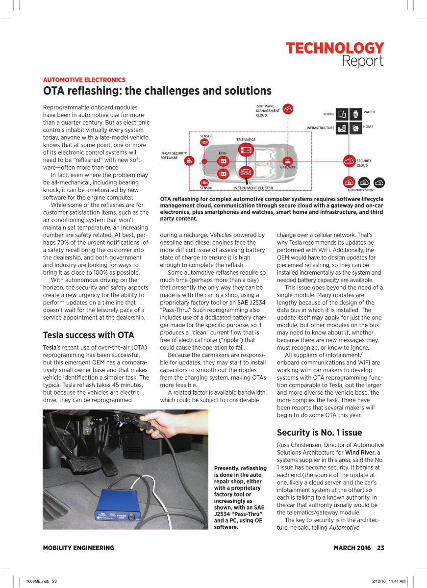
AUTOMOTIVE ELECTRONICS
OTA reflashing: the challenges and solutionsReprogrammable onboard modules have been in automotive use for more than a quarter century. But as electronic controls inhabit virtually every system today, anyone with a late-model vehicle knows that at some point, one or more of its electronic control systems will need to be “reflashed” with new soft-ware—often more than once.
In fact, even where the problem may be all-mechanical, including bearing knock, it can be ameliorated by new software for the engine computer.
While some of the reflashes are for customer satisfaction items, such as the air conditioning system that won’t maintain set temperature, an increasing number are safety related. At best, per-haps 70% of the urgent notifications of a safety recall bring the customer into the dealership, and both government and industry are looking for ways to bring it as close to 100% as possible.
With autonomous driving on the horizon, the security and safety aspects create a new urgency for the ability to perform updates on a timeline that doesn’t wait for the leisurely pace of a service appointment at the dealership.
Tesla success with OTA Tesla’s recent use of over-the-air (OTA) reprogramming has been successful, but this emergent OEM has a compara-tively small owner base and that makes vehicle identification a simpler task. The typical Tesla reflash takes 45 minutes, but because the vehicles are electric drive, they can be reprogrammed
during a recharge. Vehicles powered by gasoline and diesel engines face the more difficult issue of assessing battery state of charge to ensure it is high enough to complete the reflash.
Some automotive reflashes require so much time (perhaps more than a day) that presently the only way they can be made is with the car in a shop, using a proprietary factory tool or an SAE J2534 “Pass-Thru.” Such reprogramming also includes use of a dedicated battery char-ger made for the specific purpose, so it produces a “clean” current flow that is free of electrical noise (“ripple”) that could cause the operation to fail.
Because the carmakers are responsi-ble for updates, they may start to install capacitors to smooth out the ripples from the charging system, making OTAs more feasible.
A related factor is available bandwidth, which could be subject to considerable
change over a cellular network. That’s why Tesla recommends its updates be performed with WiFi. Additionally, the OEM would have to design updates for piecemeal reflashing, so they can be installed incrementally as the system and needed battery capacity are available.
This issue goes beyond the need of a single module. Many updates are lengthy because of the design of the data bus in which it is installed. The update itself may apply for just the one module, but other modules on the bus may need to know about it, whether because there are new messages they must recognize, or know to ignore.
All suppliers of infotainment/ onboard communications and WiFi are working with car makers to develop systems with OTA reprogramming func-tion comparable to Tesla, but the larger and more diverse the vehicle base, the more complex the task. There have been reports that several makers will begin to do some OTA this year.
Security is No. 1 issue Russ Christensen, Director of Automotive Solutions Architecture for Wind River, a systems supplier in this area, said the No. 1 issue has become security. It begins at each end (the source of the update at one, likely a cloud server, and the car’s infotainment system at the other) so each is talking to a known authority. In the car that authority usually would be the telematics/gateway module.
The key to security is in the architec-ture, he said, telling Automotive
OTA reflashing for complex automotive computer systems requires software lifecycle management cloud, communication through secure cloud with a gateway and on-car electronics, plus smartphones and watches, smart home and infrastructure, and third party content.
Presently, reflashing is done in the auto repair shop, either with a proprietary factory tool or increasingly as shown, with an SAE J2534 “Pass-Thru” and a PC, using OE software.
TECHNOLOGY Report
1603ME.indb 23 2/12/16 11:44 AM

MOBILITY ENGINEERING24 MARCH 2016
Engineering that presently such append-ages as the smartphone and watch, and keyless entry, hitherto not so considered, can be “threat vectors” into the car. He added that the CAN bus (Controller Area Network) was not designed for encryp-tion, although there are some strategies for accomplishing that.
Also required is a way to get an authenticated payload (the updated software) to the car and having an elec-tronic “place” to hold it, Christensen said. A manifest comes down with all updates; the car says okay, a signature comes from the cloud and the car validates it. The first update is then discharged to the ECU. Which raises this issue: if the instal-lation fails, the system needs to be able to activate a “restore” function to get the system back to original setting.
If there are three updates in the manifest, and the failure occurs during the third, there may need to be a removal function, so the system reflashes back to the original state.
“None of this is hard,” Christensen noted. “We just need the vehicle design to be able to do it.” He cited the exam-ple of an “atomic update,” where all updates must be installed at once or none should be.
Bypassing owner OK Christensen cited banking industry money transfers as an example of the way installations must be executed with secure protocols, where a scheduled data transfer must be completed instan-taneously, or the entire transaction goes back to its previous state.
When there is an urgent safety update, the comparatively slow pace that includes owner evaluation and approval may need a work-around. There might have to be a provision for abrogating authorization, although that would be a last resort for an OEM.
A critical aspect of the entire chal-lenge of OTA updating is identifying the vehicle configuration. Many OEMs right now do not have software configuration matrixes at a sufficient level of confi-dence to always be certain of the right software for all vehicles.
“The manufacturer can’t even rely on the VIN once the car has left the assem-bly line,” Christensen said, and certainly not if a module has been replaced.
Paul Weissler
AVIONICS
Clamoring for a connection
Rockwell Collins teamed with Inmarsat to provide wireless communications.
Many of today’s constantly connected consumers balk at spending a few hours without Web access. Commercials air-lines are responding by forging links with satellite providers that give flyers the same capabilities they have on the ground. Increasing bandwidth is one of the focal points for inflight entertain-ment and connectivity (IFEC) systems.
“High throughput satellites (HTS) are going to be launched in early 2016, which will make exponentially more capacity available,” said Panasonic Avionics Corp. spokesman Brian Bardwell. “Layering these HTS spot beams over our existing wide-beam network ensures both global coverage and the greatest throughput. Our wide-beam network today covers 99.6% of all commercial flight hours, offering up to 50 Mbps. HTS capacity that will bring 200 Mbps, as well as extremely high throughput capacity, that will bring up to 3.3 Gbps in certain regions.”
Panasonic’s satellite partner, Intelsat, currently estimates that its global broad-band aeronautical throughput is 350
Handheld devices are a central part of
Panasonic Aviation’s entertainment strategy.
Mbps. That’s expanding rapidly now that newly launched Intelsat’s EpicNG satel-lites each add 25-60 Gbps of capacity. They offer both wide and spot beams, enabling intelligent use of spectrum to provide as much as 200 Mbps to a plane flying through any given beam.
Other airline and satellite partners are making similar moves. Jazeera Airways plans to install Rockwell Collins’ PAVES Cabin Wireless and Inmarsat’s Global Xpress connectivity on its Airbus A320 aircraft by late 2016. That will let more than 500 pas-sengers stream video content simulta-neously while also using an array of apps and services.
“Inmarsat’s Global Xpress constella-tion is set to transform the passenger experience. Airlines can offer inflight connectivity that is fast, reliable and consistent, with coverage across the world,” said Leo Mondale, President of Inmarsat Aviation.
Inmarsat also equipped more than 150 Lufthansa planes with its Global Xpress commercial Ka-band satellite
TECHNOLOGY Report
1603ME.indb 24 2/12/16 11:44 AM

MOBILITY ENGINEERING MARCH 2016 25
network. Lufthansa plans to continue this rise in bandwidth.
“To keep up with the new Ka satellite technology, the Ku system used for the airlines will be upgraded to high-throughput satellites, and at a later stage to extreme high-throughput satel-lites,” said Sabine Hierschbiel, Connectivity & IFE Systems Manager at Lufthansa. “This will improve perfor-mance, providing much more band-width to the individual user.”
Passengers will readily ask for more bandwidth, but airlines and satellite pro-viders have to figure out how to provide it profitably. At some point, consumers and providers alike will determine that they’re no longer willing to continue the upward spiral. Airlines may be the ones to tell consumers that their usage will have some limits.
“All this has a natural end, either tech-nology-wise or in an economical aspect,” Hierschbiel said. “So it will be interesting to see how long the industry is willing to continue this growth, or if at some time the industry will set parameters to the kind of usage being offered inflight.”
Security will be a key factor regard-less of how much bandwidth is used. Connectivity always brings the down-side of the Internet: hackers and mal-ware. A hacker who figures out how to take control of a plane could extort huge sums.
System designers block attacks through the IFEC systems by isolating aircraft control systems from the infor-mation systems used by passengers and crew. That prevents a hacker or a problematic app from causing prob-lems with flight controls. Airlines are also ensuring that their IFEC systems aren’t compromised.
“We only use the latest IT security mechanisms to ensure the data trans-ferred over the connectivity system cannot be manipulated,” Hierschbiel said. “This includes end-to-end encryp-tion, use of certificates, hardening of connected devices, and the enforce-ment of strong passwords. Security analyses and audits are performed and continuously repeated. Additionally, airlines, aircraft manufacturers, and authorities are working together on regulation and processes to avoid the possibility of interference with any operational aircraft interface.”
Terry Costlow
COMMERCIAL VEHICLE INTERIORS
HMIs offer something for everyone
Equipment buyers typically focus on fac-tors like horsepower and lifting capability, but human-machine interfaces may be the most important factor for off-high-way vehicle operators. Differentiating these HMIs and customizing them for various models are critical factors during the development process.
Design teams must also figure out how to maintain a consistent look and feel across all the company’s vehicles. Design tools are making it simpler for developers to handle these and other tasks, often by providing a library of software modules that can be inserted to let OEMs quickly create software for common functions so they can focus on the more complex aspects of user inter-face development.
“Pre-programmed visual elements, which allow for easy customization, are available for use with a multitude of oper-ating parameters on different vehicles,” said Evan Artis, Product Manager, Electronic Controls & Software, at Eaton’s Hydraulics Group. “This allows customers to bypass much of the effort that is typi-cally required on the front-end of applica-tion development for visual HMI devices, facilitating rapid deployment.”
Those pre-programmed software modules continue to advance. When design teams get similar requests from a number of customers, they often create software that solves the issues. Some developers are already focusing on over-the-air updating, which will help OEMs reduce the cost of fixing software bugs
and update programs in the field.“Our tools are now enabling over-
the-air updates,” said Mike Juran, CEO at Altia, a supplier of UI engineering tools. “This helps OEMs keep the HMIs fresh, improve usability, add features, or fix bugs without needing a recall.”
This ability to alter software is a criti-cal factor for HMI suppliers. They must make it simple for their OEM customers to create HMIs that provide brand rec-ognition and a friendly look and feel.
“The ability to build smart operator interfaces that clearly differentiate the vehicle from the competition is very important for vehicle OEMs,” said Christiana Seethaler, Product Development Director, TTControl. “A customizable logo can be shown during boot-up of the device. Furthermore, the display application can be programmed in a way that allows end-users to adapt HMI parameters such as the menu to individual needs and preferences.”
As it becomes easier to change some parameters after vehicles leave the pro-duction line, fleet owners may get into the act. They may add company-spe-cific images or information.
“Large fleet owners like Amazon or WalMart may want to create their own experience for their own drivers,” said Manuela Papadopol, Marketing Director at Elektrobit, which makes HMI design tools. “It wouldn’t be difficult for them to create a specialized HMI that runs on top of the vehicle software.”
Terry Costlow
Fleet owners like Amazon could customize their screens using Elektrobit tools.
TECHNOLOGY Report
1603ME.indb 25 2/12/16 11:44 AM

MOBILITY ENGINEERING26 MARCH 2016
System shown in heat pump mode3-Way
Valve #12-Way Valve
& Orifice
OutsideCond.
2-WayValve Comp
Accu
3-Way Valve #2
Motor&
Inverter Chill
er
Evap
Battery
PTC HTR
A/C TXVInsideCond
AUTOMOTIVE INTERIORS
Secondary loop and heat pump climate control under evaluation once more
Is secondary loop climate control about to make an engineering splash? It got a close look for A/C when the industry was considering low-global-warming alterna-tives to R-134a, because it permitted confining a system using a refrigerant with safety/environmental issues to a safe underhood area. But once R-1234yf was seen as a safe albeit mildly-flamma-ble choice, usable with under-dash circu-lation in a direct expansion cycle with existing technology, secondary loop went into mothballs. However, at the re-cent SAE Thermal Management Systems Symposium (TMSS) it was once again identified as a promising alternative.
Direct expansion vaporizes the liquid refrigerant in the under-dash heat exchanger—the evaporator—a single heat exchange loop. A carefully pack-aged secondary loop allows safe use of R-152a, a low-cost, low-global-warming, modestly more flammable refrigerant.
However, secondary loop requires an additional heat exchange circuit—from the refrigerant to an underhood coolant chiller circulating water and antifreeze mixture into an under-dash heat exchanger for cabin climate control. The second circuit reduces overall system efficiency somewhat, of course. So why would it be worth a new look?
Heat pump, thermal storageEssentially reversing the refrigeration cycle (using control valves) allows the compressor to operate as a heat pump, both for electric vehicles (EVs) and fu-el-powered cars. If the system—A/C only
or with heat pump circuitry—is a second-ary loop, there are potential fuel-econo-my benefits with an idle stop system. The secondary loop is effectively “en-gine-off” liquid thermal storage and can provide long periods of cabin comfort.
According to a study presented at TMSS by the Department of Mechanical Engineering of the University of Maryland, the engine-off A/C cooling storage from secondary loop can be sized to exceed 10 minutes. Developing a system for thermal storage of heat for an EV is an obvious area for study, and research in that area reportedly will begin when funding, perhaps from a UN agency, becomes available.
The use of a water-antifreeze sec-ondary loop also simplifies the plumb-ing in vehicles with rear HVAC. Instead of high-pressure refrigerant lines, the system can use lower-cost heater-like lines and hoses.
Because the greatest gains are in A/C, a team of researchers looked at large population areas where the cli-mate includes a long cooling season. India, the example chosen, has winter temperatures of 20-25°C (68-77°F) in the mainland southeast, and long hot and humid warm seasons. By taking this geographic example, it could be seen if an optimized secondary loop A/C sys-tem could match or exceed the effi-ciency of a direct expansion system.
The question and accompanying research was presented at TMSS by Sangeet Kapoor and Prasanna Nagarhalli of Tata Motors, and Timothy Craig and Mark Zima of Mahle’s Delphi Thermal. They worked with refrigerant scientist James Baker and Dr. Stephen Andersen, retired EPA climate issues executive and now research director of IGSD (Institute for Governance and Sustainable Development), a non-gov-ernmental organization.
Refrigerant savingsSecondary loop is tough to package, adding a refrigerant-to-coolant heat exchanger/chiller, the pump to circulate the coolant, and extra piping. However, there is a 20% reduction in refrigerant, which results in a significant cost saving if it’s R-1234yf. Using R-152a, because it is very low in cost, saves even more. The coolant mixture used was 30% anti-freeze, 70% purified water, chosen for heat transfer efficiency.
A dynamometer test program looked at COP (Coefficient of Performance) for the secondary loop, running it through a complete Federal Test Procedure (FTP) at 28°C (82°F), the New European Drive Cycle (NEDC) at 28°C and an SCO3 cycle, the supple-mental EPA cycle for A/C operation, which is run at 33°C (91°F).
ExpansionValve
CompressorPassenger Compartment Engine Bay
Expansion Valve
Pump Compressor
Cabi
n Ai
r Flo
w
Evap
orat
or
Cond
ense
r
Cabi
n Ai
r Flo
w
Cool
er
Chille
r
Cond
ense
r
Air FlowAir Flow
Direct expansion A/C (top) vs. secondary loop.
Kia Soul EV’s switching
valves bypass evaporator and
direct hot liquid refrigerant
through under-dash inside condenser.
TECHNOLOGY Report
1603ME.indb 26 2/12/16 11:44 AM

MOBILITY ENGINEERING MARCH 2016 27
The tests were run with (1) no A/C, (2) continuous A/C with the cabin soaked to ambient temperature, (3) with the A/C compressor disengaged at idle, and (4) on acceleration. Although there was a modest improvement with the compres-sor stopped at idle, the combination with the disconnect-on-acceleration, taking greater advantage of the inherent thermal storage, produced dramatic fuel-economy improvements on all three cycles. The numbers: 6.5% on the FTP, 11.5% on the NEDC, and 12.5% on the SCO3.
R-152a has a global warming number below 150, so it is lower than interna-tional regulatory limits. Although this is higher than R-1234yf’s under 10, unlike R-1234yf it does not produce TFA (tri-fluoroacetic acid, a plant growth inhibi-tor) as a degradation product, although currently not regulated.
The compressor with a circuit reversal to operate as a heat pump, providing heat for the passenger compartment, is superior in a secondary loop because it also provides engine/EV-off heat from the thermal storage. Even a half-way step—heat pump in a direct expansion system—has demonstrated value for an electric drive vehicle, where conventional electric heating (resistance or Positive Temperature Coefficient) can sharply reduce winter driving range. The heat pump is much more efficient than con-ventional heating.
Nissan, Kia EVsBoth the Nissan Leaf and Kia Soul EV offer direct expansion heat pump sys-tems, presently using R-134a systems like the companies’ gasoline-engine
cars, but with R-1234yf on the horizon. There is a baby step into secondary loop: a water-antifreeze chiller circuit for cooling EV electronics, and Kia esti-mates a 27% improvement from the heat pump in electrical heating efficien-cy over the winter temperature range.
Conventional (resistance and Positive Temperature Coefficient) heating has a major effect on EV range in winter. A study with various sizes of cars, reported at TMSS by Dr. Gregor Homann of Volkswagen AG and Prof. Jurgen Kohler of the University of Brunswick, showed a loss of 20-50% with conventional electric heating. The greatest drop, not surpris-ingly, was suffered by the smallest vehi-cle, which has the smallest battery pack, in testing at -7°C (+19°F).
Heat pumps have a positive COP in ambient temperatures starting from above -15 to -18°C (0 to +5°F). They approach 2.8-3.5 at 10°C (50°F), the COP depending on refrigerant used and pump design. So although the heat pump makes a significantly positive contribution at moderately cold tem-peratures, in really cold weather con-ventional electric heating still is needed.
The heat pump might draw heat from warmer sources than ambient air, such as EV electronics, motor, and the battery pack. But these would require packaging a sophisticated ducting system and can make only minor contributions, if any, at low ambient temperatures. In many areas, however, the ambient tempera-tures during heating seasons are suffi-ciently high to make the heat pump a valuable addition for both EVs and even many fuel-powered vehicles.
Paul Weissler
AEROSPACE INTERIORS
SABIC showcases customizable sheet, 3D seat for aircraft interiorsSABIC recently showcased various ma-terial solutions for aircraft interiors that it believes can help airlines to reduce weight, differentiate their brands, mini-mize costs, and enhance their custom-ers’ flying experiences. Chief among these offerings is a new decorative sheet material to help customize the inside of planes and a 3D-printed econ-omy class aircraft seat.
The clarity and compliance limita-tions of traditional transparent materials are two factors that often restrict air-craft interior designers, according to SABIC. A new clear polycarbonate material from the supplier’s Polymershapes business, called Jet Panel sheet, reportedly offers designers more flexibility with a variety of custom colors, textures, and the ability to embed natural materials such as plant fibers to create unique interior ele-ments, such as dividers, security parti-tions, oversized interior windows, and back-lit signs.
The new sheet delivers 80% light transmission at 2-mm thickness. Based on SABIC’s Lexan XHR2000 sheet, Jet Panel is the first fully customizable and fully transparent material that complies
The prototype 3D printed seat, fabricated using filament made from SABIC’s Ultem
9085 resin, was created to inspireseating tiers to take a
fresh look at design andalternative manufacturing
methods.
Chart shows heater-caused loss of range in cold weather in different size EVs.
Source: Auto, Motor und Sport (2011)
TECHNOLOGY Report
1603ME.indb 27 2/12/16 11:44 AM

MOBILITY ENGINEERING28 MARCH 2016
with FST (flame, smoke, and toxicity) regulations such as FAR25.853, BSS7239 and ABD0031, and OSU 65/65 heat release requirements, as well as OEM specifications, the company claims.
Jet Panel sheet was in development for approximately 18 months, which took place in the U.S. and Europe. Challenges included working on a variety of designs that would meet regulatory requirements in final form and on a lot-to-lot basis, according to a company spokesperson.
Available exclusively through Polymershapes, Jet Panel is offered in minimum order quantities as low as one sheet.
“Our approach to the market employs use of a sample kit showing a number of designs ready for use. As the ability to customize is one of the key attributes of Jet Panel sheet, we believe end-users and the aerospace design community will drive further customization for these panel designs to fit an overall branding strategy for their respective airlines,” the spokes-person added.
SABIC’s other innovation, a proto-type 3D-printed economy class seat, capitalizes on the growing trend to cre-ate 3D-printed components or systems that promise reductions in assembly time, part counts, and weight.
“3D printing is already in use by sup-pliers to the aerospace industry, as it has demonstrated its value in quickly creat-ing low volume, highly complex shapes for air ducts, fluid handling, and other components within a plane’s hidden spaces,” said the spokesperson. “Using 3D printing allows for rapid prototyping and production, without the time or expense typically required for tooling.”
The company licensed the Studio Gavari design for a sleek and ergonomi-cally advanced seat. By doing so, it hopes “to inspire seating tiers to take a fresh look at seat design and fabrication.”
“It is not a flyable seat, but it was fabricated using filament made from SABIC’s Ultem 9085 resin, which is an aircraft-compliant thermoplastic mate-rial,” the spokesperson noted. “The seat also shows the potential for part consolidation.”
Use of 3D printing resulted in a seat with less than 15 components, com-pared to traditionally fabricated seats that can contain upwards of 150 sepa-rate parts.
Ultem 9085 resin is “highly compati-ble” with 3D printing, according to SABIC, and meets aircraft industry and OEM-specific heat release and FST requirements.
Ryan Gehm
Jet Panel polycarbonate sheet, which is based on SABIC’s Lexan XHR2000 sheet, is claimed to be the first fully customizable and fully transparent material that complies with FST regulations and OSU 65/65 heat release requirements.
AUTOMOTIVE BODY
Ford looks to spread Corning’s new lightweight Gorilla Glass beyond the 2017 GTWhile many supercar enthusiasts have “gone ape” over the Ford 2017 GT, the program development engineers have done the same for a new lightweight glazing solution.
Called “Gorilla Glass,” the three-layer laminate is claimed by its supplier, Corning Inc., to deliver more than five times the strength, pound for pound, of conventional automotive glass while offering significant mass reduction. In the case of the GT, more than 12 lb (5.4 kg) was saved by using Gorilla Glass in three areas: the windshield (first use for a production vehicle), the rear window, and in an acoustic separator in the rear bulkhead. It also helped reduce the car’s center of gravity by 3 mm (0.12 in).
Ford engineers are delighted with the performance of the new glass and are looking to increase its vehicle appli-cations beyond the GT.
Introduced in 2007 as a thin, durable screen material for smartphones and tablets, Gorilla Glass is currently used on 4.5 billion mobile devices from a variety of global consumer-electronics brands. Since then Corning has been developing an automotive-grade variant that is produced using a twist on the ion-exchange process used in alumina silica glass manufacturing. PGW (Pittsburgh Glass Works) also played a role in the material’s development.
Ford’s Fusion MMLV (Multi-Material Lightweight Vehicle) concept car debuted Gorilla Glass in 2014 in its windshield and side windows, delivering a 30% reduction in glazing weight, the companies claim.
The GT windshield is a tri-layer lami-nate comprised of a 0.7-mm (0.028-in) -thick inner layer of Gorilla Glass for Automotive, a 2.1-mm (0.08-in) outside layer of annealed soda-lime glass, and a 0.76-mm (0.03-in) resin foil interlayer. The Corning product enables the glass layers to be up to 50% thinner than con-ventional vehicle glass.
Work for the supercar application began in late 2014. “It was an accelerated
TECHNOLOGY Report
1603ME.indb 28 2/12/16 11:44 AM

MOBILITY ENGINEERING MARCH 2016 29
development program,” observed Paul Linden, Ford’s Advanced Mechanisms Body Exterior Lead. “We completed all our application testing in four months. The AR (application readiness) approval process typically takes us up to two years. My boss Ali Jamul put the team together and gave us the budget to build and test the vehicles. We went into this thinking it was a win-win, which it is, so we pulled out all the stops.”
As the GT program itself was also on a fast track, Jamul’s team completed its testing regime, including overlap, back-to-back, and rollover, on the vehicle’s critical path.
The new lightweight glazing technol-ogy offers opportunities across Ford’s global vehicle line, noted Hau Thai-Tang, Ford’s Group Vice President, Global Purchasing. He said a typical passenger vehicle has about 50 ft² (4.6 m²)—about 80 lb (36 kg)—of glass. A Ford Explorer with sunroof is laden with about 200 lb (91 kg), so a significant reduction in glazing-system mass has a “cascade”
effect on surrounding body structure, such as A-pillar cross section, wind-shield headers, and the upper cowl.
“The big thing for us in designing bod-ies is looking at not only static stiffness but also dynamic stiffness,” explained Thai-Tang, a veteran vehicle engineer and accomplished racecar driver. “Dynamic stiffness is the square root of k/m, so the lighter you can make the body-in-white system for the same equivalent torsional stiffness, the more you can drive up the dynamic stiffness. And that’s where we’re seeing the improvements with this glass technology.”
He said that in the GT application, the advantage of Gorilla Glass comes from more than the stiffer material. “It’s also a function of the windshield or win-dow’s shape; the GT’s windshield has a lot of curvature,” he told Automotive Engineering. “That was part of the answer to the different thicknesses of the laminate. We have some built-in tension in the glass system that adds the stiffness. But the main thing is we’re driving the mass down so the dynamic stiffness, the ‘k’ factor, increases.”
Panoramic sunroofs, which place sig-nificant glass mass far above a vehicle’s center of gravity, “are a huge potential application for this technology,” Thai-Tang said. “It’s clearly a big area we’re looking at.”
Gorilla Glass for Automotive also provides optical advantages compared with conventional float glass. It has no optical draw lines, making it ideal for extremely “fast” (low angle) windshield
Ballistics test demo at Ford replicates a 55-mph hailstone strike on a piece of Gorilla Glass for Automotive without damage to the glass. (All photos by Lindsay Brooke)
Paul Linden, Ford’s Advanced Mechanisms Body Exterior Lead and glass technology veteran, noted that all application testing of the Gorilla Glass program for the GT was completed in four months.
applications as in the GT.“A lot of times we can’t execute what
our designers want because of the glass distortion,” noted Thai-Tang. “Distortion is also a factor when you introduce HUDs [head-up displays], LiDARs, and radars. As we bring in more autonomous driving technologies, you can imagine a day where we project images and informa-tion onto the glass. In an autonomous vehicle the elimination of optical distor-tion becomes an important factor.”
The GT racecars being prepared by Ford and Multimatic will use Gorilla Glass in the 24 Hours of LeMans in June, he confirmed. While the car’s headlamp lens covers will remain polycarbonate initially, Ford engineers are looking at other applications including the interior.
“Instead of just having an informa-tion screen you can have a full center console that is a Gorilla Glass surface,” he asserted. “All the things being done in the consumer-electronics space for tablets and phones is applicable in vehi-cles. We want to pair the Corning tech-nology with not only the exterior guys but also the interior designers. But you won’t see us use Gorilla Glass on a refresh—the thinner glass will drive new door and body structures.”
The new exterior-glazing system requires no change to the vehicle assembly process; the Gorilla Glass components are installed using conven-tional robotics and urethane-bonding system. Corning produces the glass at its Harrodsburg, KY, plant.
Lindsay Brooke
Ford’s 2017 GT is the first production car to use Corning’s new glazing technology in a windshield application. Will SUVs be next?
TECHNOLOGY Report
1603ME.indb 29 2/12/16 11:44 AM

MOBILITY ENGINEERING30 MARCH 2016
AUTOMOTIVE BODY & CHASSIS
2016 Civic structure employs ‘first’ partial in-die soft zonesThe 2016 Honda Civic employs selec-tively-tempered in-die “soft zone” tech-nology in the B-pillars and rear frame rails, allowing zones within a single frame piece to have more ductile prop-erties than the surrounding ultra-high-strength hot-stamped steel. The tech-nology minimizes parts count and saves 15.6 lb (7 kg) compared to the previ-ous-generation Civic.
“Our method of application for this [in the rear frame rail] is a world’s first,” according to Ryan Miller, Performance Development Leader for the 2016 Civic. “Full-band soft zones [such as in the B-pillar] have been done before on a few other cars, but what we’ve done that’s unique is we’ve created partial soft zones; this is much more difficult to do.”
Honda co-developed this specific application with supplier Gestamp over the past three years.
“These soft zones give us the ability to completely control the frame crush mode and prevent cracking of the frame at the same time. It’s one stamped piece of material and we con-trol it by material property, not by thickness or any kind of tailor welding,” Miller explained.
The partial soft zones in the Civic’s rear frame rail varies from about 590-MPa advanced high-strength steel to 1500-MPa press-hardened steel.
“In a crash, we want this [part] to do an ‘accordion crush’—every bend absorbs energy. Without putting any geometric divots or anything like that in, it starts to crush here, then there, then there,” he said, pointing to the three varying soft
zones. “So the whole thing ‘accordians’ up and prevents any cracking from happen-ing in the high-strength steel. You can’t do that if you do full band, so that’s why we developed it this way.”
The process involves heating the sheet steel to 930°C (1706°F) before simultane-ously stamping and cooling key areas of the part. A laser cutting trimming process then completes the component.
“During the stamping process, there’s cooling lines that are applied in just certain areas that cool the material at different rates and create a different amount of tempering. It actually creates a different material grade even though it’s still one part, one thickness, and one stamping,” he said.
The soft zones in the rear frame rail address two important issues: rigidity and weight.
“The traditional way of doing it is to use multiple parts. Body rigidity is based on section size or thickness of
the material. If this was regular-grade material and we didn’t have these [soft zones], you’d have to put discontinuities in there—physical bend points to force it to bend where you want it to. Every time you do that you actually decrease the section in that area and then you lose rigidity,” Miller explained. “The other issue is that you have to absorb a given amount of energy, which means the material would have to be thicker, increasing weight. [This technology] solves those problems—it improves rigidity and reduces the weight.”
The next potential application for in-die soft zones is in the front frame rail, according to Miller. “It behaves very similarly to this [rear frame rail] except for the [crash] testing is a lot more extensive up there. Theoretically, that would be the next location.”
For more on the 2016 Civic, visit http://articles.sae.org/14351/.
Ryan Gehm
The partial soft zone on the 2016 Civic’s rear frame rail varies from about 590-MPa advanced high-strength steel (pink) to 1500-MPa press-hardened steel (deep purple). The yellow depicts the transition zone between the two grades. (Photo by Ryan Gehm)
Ryan Miller, Performance Development Leader for the 2016 Honda Civic, poses with the rear-frame-rail partial soft zone. (Photo by Ryan Gehm)
The 2016 Civic’s B-pillars also employ in-die soft zones, but of the full-band variety.
TECHNOLOGY Report
1603ME.indb 30 2/12/16 11:44 AM
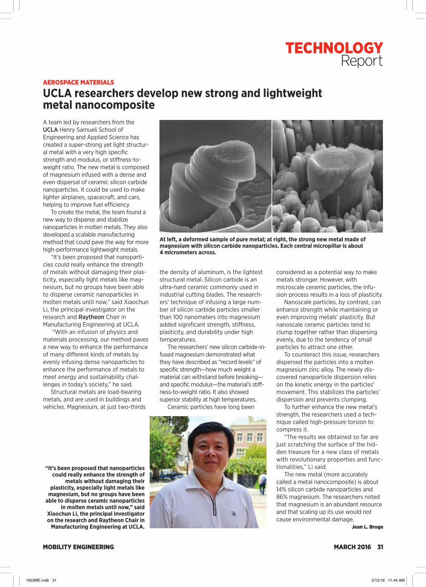
MOBILITY ENGINEERING MARCH 2016 31
AEROSPACE MATERIALS
UCLA researchers develop new strong and lightweight metal nanocompositeA team led by researchers from the UCLA Henry Samueli School of Engineering and Applied Science has created a super-strong yet light structur-al metal with a very high specific strength and modulus, or stiffness-to-weight ratio. The new metal is composed of magnesium infused with a dense and even dispersal of ceramic silicon carbide nanoparticles. It could be used to make lighter airplanes, spacecraft, and cars, helping to improve fuel efficiency.
To create the metal, the team found a new way to disperse and stabilize nanoparticles in molten metals. They also developed a scalable manufacturing method that could pave the way for more high-performance lightweight metals.
“It’s been proposed that nanoparti-cles could really enhance the strength of metals without damaging their plas-ticity, especially light metals like mag-nesium, but no groups have been able to disperse ceramic nanoparticles in molten metals until now,” said Xiaochun Li, the principal investigator on the research and Raytheon Chair in Manufacturing Engineering at UCLA.
“With an infusion of physics and materials processing, our method paves a new way to enhance the performance of many different kinds of metals by evenly infusing dense nanoparticles to enhance the performance of metals to meet energy and sustainability chal-lenges in today’s society,” he said.
Structural metals are load-bearing metals, and are used in buildings and vehicles. Magnesium, at just two-thirds
the density of aluminum, is the lightest structural metal. Silicon carbide is an ultra-hard ceramic commonly used in industrial cutting blades. The research-ers’ technique of infusing a large num-ber of silicon carbide particles smaller than 100 nanometers into magnesium added significant strength, stiffness, plasticity, and durability under high temperatures.
The researchers’ new silicon carbide-in-fused magnesium demonstrated what they have described as “record levels” of specific strength—how much weight a material can withstand before breaking—and specific modulus—the material’s stiff-ness-to-weight ratio. It also showed superior stability at high temperatures.
Ceramic particles have long been
considered as a potential way to make metals stronger. However, with microscale ceramic particles, the infu-sion process results in a loss of plasticity.
Nanoscale particles, by contrast, can enhance strength while maintaining or even improving metals’ plasticity. But nanoscale ceramic particles tend to clump together rather than dispersing evenly, due to the tendency of small particles to attract one other.
To counteract this issue, researchers dispersed the particles into a molten magnesium zinc alloy. The newly dis-covered nanoparticle dispersion relies on the kinetic energy in the particles’ movement. This stabilizes the particles’ dispersion and prevents clumping.
To further enhance the new metal’s strength, the researchers used a tech-nique called high-pressure torsion to compress it.
“The results we obtained so far are just scratching the surface of the hid-den treasure for a new class of metals with revolutionary properties and func-tionalities,” Li said.
The new metal (more accurately called a metal nanocomposite) is about 14% silicon carbide nanoparticles and 86% magnesium. The researchers noted that magnesium is an abundant resource and that scaling up its use would not cause environmental damage.
Jean L. Broge
“It’s been proposed that nanoparticles could really enhance the strength of
metals without damaging their plasticity, especially light metals like
magnesium, but no groups have been able to disperse ceramic nanoparticles
in molten metals until now,” said Xiaochun Li, the principal investigator on the research and Raytheon Chair in
Manufacturing Engineering at UCLA.
At left, a deformed sample of pure metal; at right, the strong new metal made of magnesium with silicon carbide nanoparticles. Each central micropillar is about 4 micrometers across.
TECHNOLOGY Report
1603ME.indb 31 2/12/16 11:44 AM
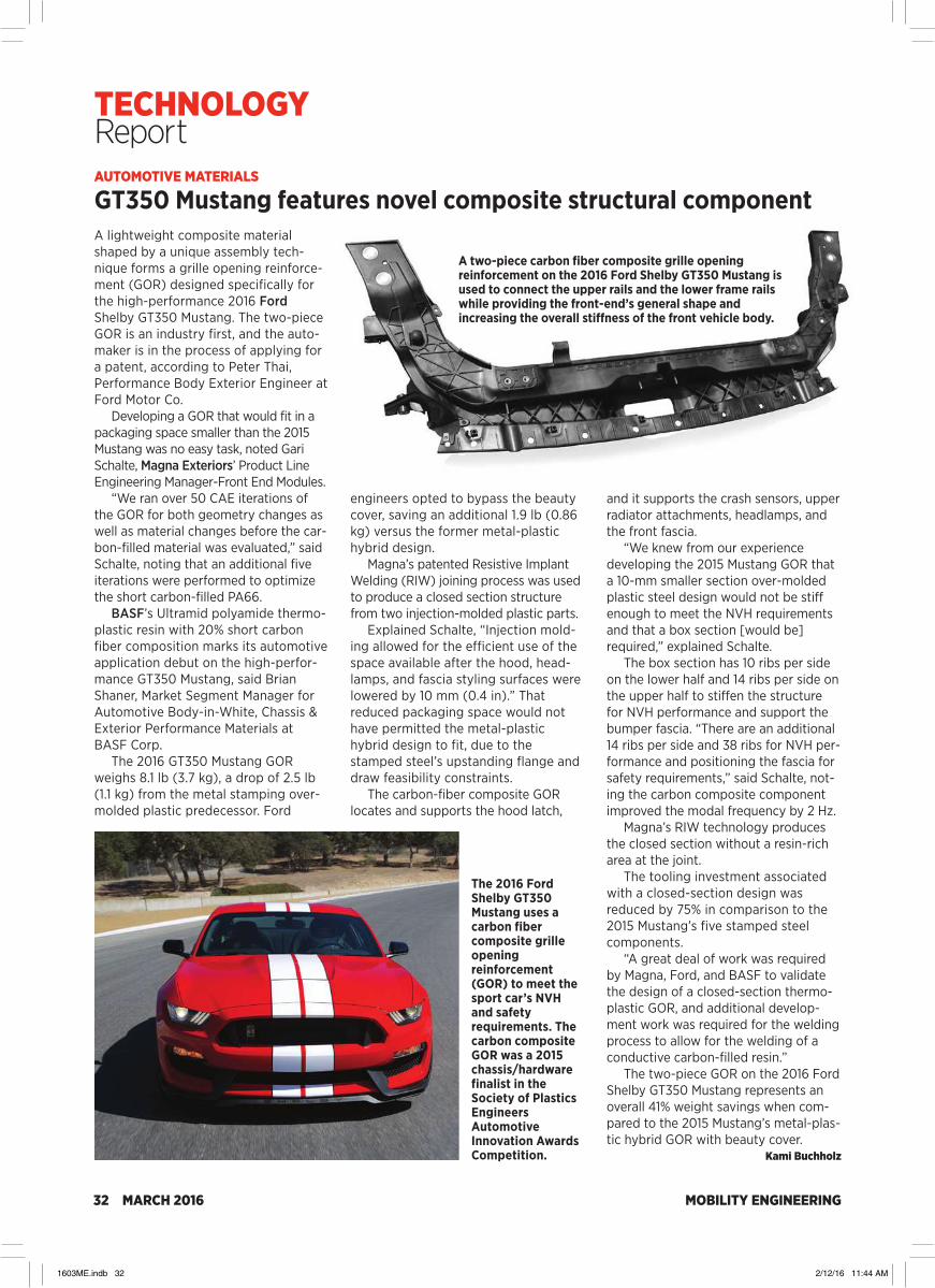
MOBILITY ENGINEERING32 MARCH 2016
AUTOMOTIVE MATERIALS
GT350 Mustang features novel composite structural component
The 2016 Ford Shelby GT350 Mustang uses a carbon fiber composite grille opening reinforcement (GOR) to meet the sport car’s NVH and safety requirements. The carbon composite GOR was a 2015 chassis/hardware finalist in the Society of Plastics Engineers Automotive Innovation Awards Competition.
A lightweight composite material shaped by a unique assembly tech-nique forms a grille opening reinforce-ment (GOR) designed specifically for the high-performance 2016 Ford Shelby GT350 Mustang. The two-piece GOR is an industry first, and the auto-maker is in the process of applying for a patent, according to Peter Thai, Performance Body Exterior Engineer at Ford Motor Co.
Developing a GOR that would fit in a packaging space smaller than the 2015 Mustang was no easy task, noted Gari Schalte, Magna Exteriors’ Product Line Engineering Manager-Front End Modules.
“We ran over 50 CAE iterations of the GOR for both geometry changes as well as material changes before the car-bon-filled material was evaluated,” said Schalte, noting that an additional five iterations were performed to optimize the short carbon-filled PA66.
BASF’s Ultramid polyamide thermo-plastic resin with 20% short carbon fiber composition marks its automotive application debut on the high-perfor-mance GT350 Mustang, said Brian Shaner, Market Segment Manager for Automotive Body-in-White, Chassis & Exterior Performance Materials at BASF Corp.
The 2016 GT350 Mustang GOR weighs 8.1 lb (3.7 kg), a drop of 2.5 lb (1.1 kg) from the metal stamping over-molded plastic predecessor. Ford
engineers opted to bypass the beauty cover, saving an additional 1.9 lb (0.86 kg) versus the former metal-plastic hybrid design.
Magna’s patented Resistive Implant Welding (RIW) joining process was used to produce a closed section structure from two injection-molded plastic parts.
Explained Schalte, “Injection mold-ing allowed for the efficient use of the space available after the hood, head-lamps, and fascia styling surfaces were lowered by 10 mm (0.4 in).” That reduced packaging space would not have permitted the metal-plastic hybrid design to fit, due to the stamped steel’s upstanding flange and draw feasibility constraints.
The carbon-fiber composite GOR locates and supports the hood latch,
and it supports the crash sensors, upper radiator attachments, headlamps, and the front fascia.
“We knew from our experience developing the 2015 Mustang GOR that a 10-mm smaller section over-molded plastic steel design would not be stiff enough to meet the NVH requirements and that a box section [would be] required,” explained Schalte.
The box section has 10 ribs per side on the lower half and 14 ribs per side on the upper half to stiffen the structure for NVH performance and support the bumper fascia. “There are an additional 14 ribs per side and 38 ribs for NVH per-formance and positioning the fascia for safety requirements,” said Schalte, not-ing the carbon composite component improved the modal frequency by 2 Hz.
Magna’s RIW technology produces the closed section without a resin-rich area at the joint.
The tooling investment associated with a closed-section design was reduced by 75% in comparison to the 2015 Mustang’s five stamped steel components.
“A great deal of work was required by Magna, Ford, and BASF to validate the design of a closed-section thermo-plastic GOR, and additional develop-ment work was required for the welding process to allow for the welding of a conductive carbon-filled resin.”
The two-piece GOR on the 2016 Ford Shelby GT350 Mustang represents an overall 41% weight savings when com-pared to the 2015 Mustang’s metal-plas-tic hybrid GOR with beauty cover.
Kami Buchholz
A two-piece carbon fiber composite grille opening reinforcement on the 2016 Ford Shelby GT350 Mustang is used to connect the upper rails and the lower frame rails while providing the front-end’s general shape and increasing the overall stiffness of the front vehicle body.
TECHNOLOGY Report
1603ME.indb 32 2/12/16 11:44 AM
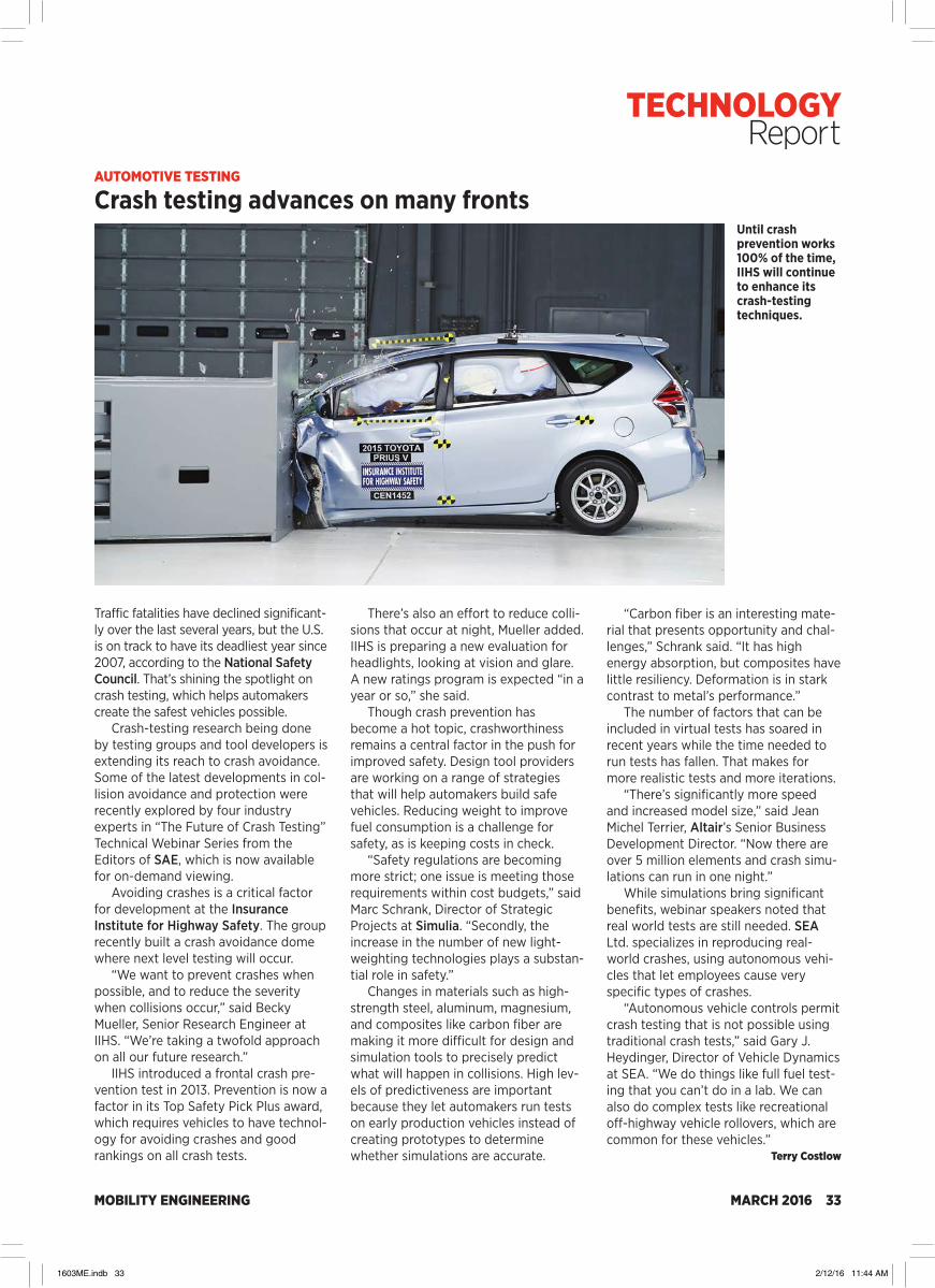
MOBILITY ENGINEERING MARCH 2016 33
AUTOMOTIVE TESTING
Crash testing advances on many fronts
Traffic fatalities have declined significant-ly over the last several years, but the U.S. is on track to have its deadliest year since 2007, according to the National Safety Council. That’s shining the spotlight on crash testing, which helps automakers create the safest vehicles possible.
Crash-testing research being done by testing groups and tool developers is extending its reach to crash avoidance. Some of the latest developments in col-lision avoidance and protection were recently explored by four industry experts in “The Future of Crash Testing” Technical Webinar Series from the Editors of SAE, which is now available for on-demand viewing.
Avoiding crashes is a critical factor for development at the Insurance Institute for Highway Safety. The group recently built a crash avoidance dome where next level testing will occur.
“We want to prevent crashes when possible, and to reduce the severity when collisions occur,” said Becky Mueller, Senior Research Engineer at IIHS. “We’re taking a twofold approach on all our future research.”
IIHS introduced a frontal crash pre-vention test in 2013. Prevention is now a factor in its Top Safety Pick Plus award, which requires vehicles to have technol-ogy for avoiding crashes and good rankings on all crash tests.
There’s also an effort to reduce colli-sions that occur at night, Mueller added. IIHS is preparing a new evaluation for headlights, looking at vision and glare. A new ratings program is expected “in a year or so,” she said.
Though crash prevention has become a hot topic, crashworthiness remains a central factor in the push for improved safety. Design tool providers are working on a range of strategies that will help automakers build safe vehicles. Reducing weight to improve fuel consumption is a challenge for safety, as is keeping costs in check.
“Safety regulations are becoming more strict; one issue is meeting those requirements within cost budgets,” said Marc Schrank, Director of Strategic Projects at Simulia. “Secondly, the increase in the number of new light-weighting technologies plays a substan-tial role in safety.”
Changes in materials such as high-strength steel, aluminum, magnesium, and composites like carbon fiber are making it more difficult for design and simulation tools to precisely predict what will happen in collisions. High lev-els of predictiveness are important because they let automakers run tests on early production vehicles instead of creating prototypes to determine whether simulations are accurate.
“Carbon fiber is an interesting mate-rial that presents opportunity and chal-lenges,” Schrank said. “It has high energy absorption, but composites have little resiliency. Deformation is in stark contrast to metal’s performance.”
The number of factors that can be included in virtual tests has soared in recent years while the time needed to run tests has fallen. That makes for more realistic tests and more iterations.
“There’s significantly more speed and increased model size,” said Jean Michel Terrier, Altair’s Senior Business Development Director. “Now there are over 5 million elements and crash simu-lations can run in one night.”
While simulations bring significant benefits, webinar speakers noted that real world tests are still needed. SEA Ltd. specializes in reproducing real-world crashes, using autonomous vehi-cles that let employees cause very specific types of crashes.
“Autonomous vehicle controls permit crash testing that is not possible using traditional crash tests,” said Gary J. Heydinger, Director of Vehicle Dynamics at SEA. “We do things like full fuel test-ing that you can’t do in a lab. We can also do complex tests like recreational off-highway vehicle rollovers, which are common for these vehicles.”
Terry Costlow
Until crash prevention works 100% of the time, IIHS will continue to enhance its crash-testing techniques.
TECHNOLOGY Report
1603ME.indb 33 2/12/16 11:44 AM

MOBILITY ENGINEERING34 MARCH 2016
OFF-HIGHWAY SIMULATION
Evaluating new forestry machines in a fraction of the time
The predominant forest harvesting method used in northern Europe is cut-to-length logging (CTL). CTL is based on a two-machine solution—a harvester is used for felling, delimbing, and buck-ing trees, and a forwarder carries the logs from the harvesting area to a road-side loading area where they can be picked up by a truck. These are both off-highway machines with a frame-mounted crane that operate in areas not accessible by conventional wheeled vehicles at low speed.
To stay competitive, the Swedish log-ging industry needs to increase produc-tivity by 2-3% per year. Increasing the speed with which forwarders can move logs is one area where logging compa-nies are hoping to achieve productivity improvements.
“A key limitation in the ability of for-warding machines to drive in the terrain is the vibrations that the driver is exposed to,” said Abbos Ismoilov, Ph.D. student at KTH Royal Institute of Technology. “In addition, forestry machines are heavy and the risk for rut-ting and soil compaction is high. Improving the productivity of forest machines will require new suspension
equipped with bogie suspension sys-tems. Bogies serve as a mechanism for averaging and smoothing the path of the center of gravity of the vehicle when it encounters obstacles in the terrain, but with bogie suspensions the only damp-ing is provided by the tires. Thus, severe limitations exist on the speed with which bogie machines can be driven without generating excessive vibrations in the cabin and causing soil damage.
One alternative that is being consid-ered is a pendulum suspended system in which each wheel is independently mounted on a link arm that is mounted on a revolute joint on the main frame. Usually a hydraulic cylinder is mounted between the arm and the frame to pro-vide vibration damping and potentially also a leveling function.
A fully suspended six-wheel proto-type was recently manufactured and assembled. This pendulum arm-sus-pended forwarder prototype will serve as a demonstrator of suspended logging machine technology and a research tool for active control and automation. A pendulum suspension enables all wheels to adapt individually to the terrain, mak-ing it easier to pass over large obstacles
Traditional forwarder on a steep slope.
Adams model and the physical test model of a traditional forwarder.
Simulation of a forwarder with pendulum arm suspension going over an obstacle.
systems that offer improved operator comfort and are gentler to the soil than current designs.”
A fully suspended forwarder prototypeSkogforsk (the Forestry Research Institute of Sweden) is the central re-search body for the Swedish forestry sector, and is financed jointly by the gov-ernment and the members of the Institute who include most of the major manufacturers of forestry equipment. Skogforsk has funded a KTH research initiative intended to help improve the suspension of forestry machines with the goal of achieving significant productivity improvements. But improving the design of forestry machines using conventional methods is very expensive and time con-suming. It can easily cost millions of dol-lars to build a prototype and test it in remote logging regions. KTH’s mission is to streamline the design process by vali-dating the capability to simulate the op-eration of forestry machines under re-al-world operating conditions.
Most current forwarders on the mar-ket have articulated steering and are
TECHNOLOGY Report
1603ME.indb 34 2/12/16 11:44 AM

MOBILITY ENGINEERING MARCH 2016 35
with good ride comfort. In addition, a pendulum suspension can be upgraded to an active system.
KTH researchers were asked to simu-late the new forwarder and validate the ability of the simulation to accurately predict its performance under realistic operating conditions.
Simulating suspension configurationsKTH researchers used MSC Software’s Adams to model three different suspen-sion concept configurations. The first is a standard Komatsu bogie forwarder with the wheels mounted on four bo-gies. The second configuration is a six-wheel machine with rear bogies and pendulum suspension for the two front wheels. The front and rear frames are connected with a roll joint and an artic-ulation joint so they cannot move verti-cally relative to each other. A variant of the second configuration has an addi-tional linkage between the middle joint and front frame to enable the front frame and cabin to move vertically rela-tive to the rear frame. The third configu-ration is a six-wheel vehicle with all wheels individually mounted on sepa-rate pendulum arms.
The CAD model with the dimension and mass parameters of a popular indus-try forwarder was imported into Adams. Three variants of the model were devel-oped and simulated on a representation of the standard Skogforsk hard ground test track. FTire was used to model the tires based on regular tire properties such as diameter and inflation pressure. Adams
calculated the wheel forces, joint forces, displacements, velocities, and accelera-tions on the test track. The time history responses were imported to MathWorks’ Matlab and transformed to the frequency domain for further analysis.
The performance of each concept was analyzed and its performance in terms of operator comfort and impact on the soil were estimated relative to the performance of the traditional for-warder. The relative values were defined in such a way that higher values indi-cate higher performance. The vehicle with the pendulum suspension per-formed substantially better than all of the other configurations. The simulation results for the traditional forwarder and pendulum suspended forwarder were compared to the existing prototypes, and both provided a very good match.
Real forwarder undergoing bump test on proving ground. Adams model simulating the same bump test.
Comparison between roll rate predicted by simulation (red) and measured during testing (blue) for front wagon (top chart) and rear wagon (bottom chart) of forwarder.
“Now that we have validated the ability of Adams to accurately simulate the per-formance of forwarders, we will be able to evaluate new design alternatives and opti-mize the performance of concept configu-rations in a fraction of the time required by the build and test method,” Ismoilov said. “The ability to evaluate more designs in less time will make it possible to optimize the suspension and other components of the vehicle to provide higher productivity without causing discomfort to the opera-tor or damage to the soil.”
Yijun Fan, Product Marketing Manager for Adams and Easy5 at MSC Software Corp., wrote this article for Off-Highway Engineering. This case study is based on an interview with Abbos Ismoilov, KTH Royal Institute of Technology, Sweden.
Yijun Fan
TECHNOLOGY Report
1603ME.indb 35 2/12/16 11:44 AM
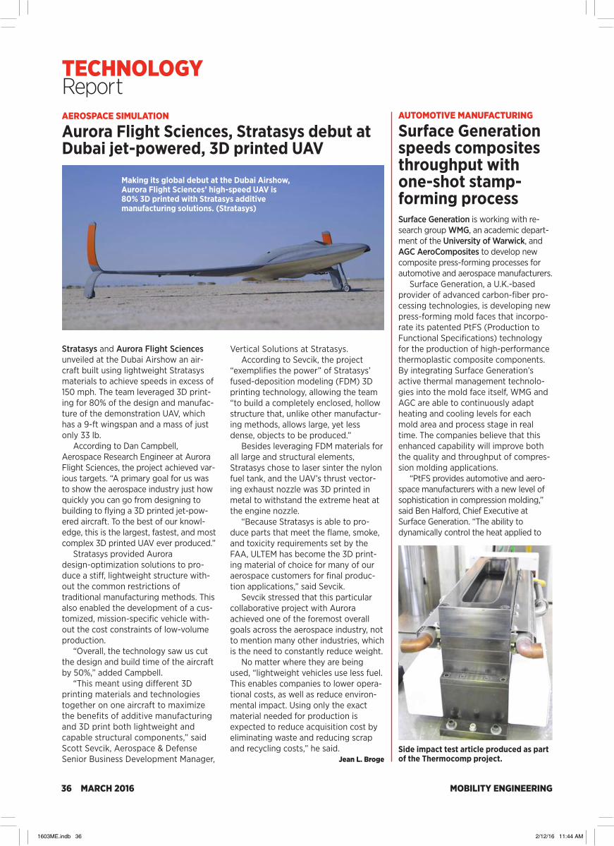
MOBILITY ENGINEERING36 MARCH 2016
AEROSPACE SIMULATION
Aurora Flight Sciences, Stratasys debut at Dubai jet-powered, 3D printed UAV
Stratasys and Aurora Flight Sciences unveiled at the Dubai Airshow an air-craft built using lightweight Stratasys materials to achieve speeds in excess of 150 mph. The team leveraged 3D print-ing for 80% of the design and manufac-ture of the demonstration UAV, which has a 9-ft wingspan and a mass of just only 33 lb.
According to Dan Campbell, Aerospace Research Engineer at Aurora Flight Sciences, the project achieved var-ious targets. “A primary goal for us was to show the aerospace industry just how quickly you can go from designing to building to flying a 3D printed jet-pow-ered aircraft. To the best of our knowl-edge, this is the largest, fastest, and most complex 3D printed UAV ever produced.”
Stratasys provided Aurora design-optimization solutions to pro-duce a stiff, lightweight structure with-out the common restrictions of traditional manufacturing methods. This also enabled the development of a cus-tomized, mission-specific vehicle with-out the cost constraints of low-volume production.
“Overall, the technology saw us cut the design and build time of the aircraft by 50%,” added Campbell.
“This meant using different 3D printing materials and technologies together on one aircraft to maximize the benefits of additive manufacturing and 3D print both lightweight and capable structural components,” said Scott Sevcik, Aerospace & Defense Senior Business Development Manager,
Vertical Solutions at Stratasys.According to Sevcik, the project
“exemplifies the power” of Stratasys’ fused-deposition modeling (FDM) 3D printing technology, allowing the team “to build a completely enclosed, hollow structure that, unlike other manufactur-ing methods, allows large, yet less dense, objects to be produced.”
Besides leveraging FDM materials for all large and structural elements, Stratasys chose to laser sinter the nylon fuel tank, and the UAV’s thrust vector-ing exhaust nozzle was 3D printed in metal to withstand the extreme heat at the engine nozzle.
“Because Stratasys is able to pro-duce parts that meet the flame, smoke, and toxicity requirements set by the FAA, ULTEM has become the 3D print-ing material of choice for many of our aerospace customers for final produc-tion applications,” said Sevcik.
Sevcik stressed that this particular collaborative project with Aurora achieved one of the foremost overall goals across the aerospace industry, not to mention many other industries, which is the need to constantly reduce weight.
No matter where they are being used, “lightweight vehicles use less fuel. This enables companies to lower opera-tional costs, as well as reduce environ-mental impact. Using only the exact material needed for production is expected to reduce acquisition cost by eliminating waste and reducing scrap and recycling costs,” he said.
Jean L. Broge
Making its global debut at the Dubai Airshow, Aurora Flight Sciences’ high-speed UAV is 80% 3D printed with Stratasys additive manufacturing solutions. (Stratasys)
AUTOMOTIVE MANUFACTURING
Surface Generation speeds composites throughput with one-shot stamp-forming processSurface Generation is working with re-search group WMG, an academic depart-ment of the University of Warwick, and AGC AeroComposites to develop new composite press-forming processes for automotive and aerospace manufacturers.
Surface Generation, a U.K.-based provider of advanced carbon-fiber pro-cessing technologies, is developing new press-forming mold faces that incorpo-rate its patented PtFS (Production to Functional Specifications) technology for the production of high-performance thermoplastic composite components. By integrating Surface Generation’s active thermal management technolo-gies into the mold face itself, WMG and AGC are able to continuously adapt heating and cooling levels for each mold area and process stage in real time. The companies believe that this enhanced capability will improve both the quality and throughput of compres-sion molding applications.
“PtFS provides automotive and aero-space manufacturers with a new level of sophistication in compression molding,” said Ben Halford, Chief Executive at Surface Generation. “The ability to dynamically control the heat applied to
Side impact test article produced as part of the Thermocomp project.
TECHNOLOGY Report
1603ME.indb 36 2/12/16 11:44 AM
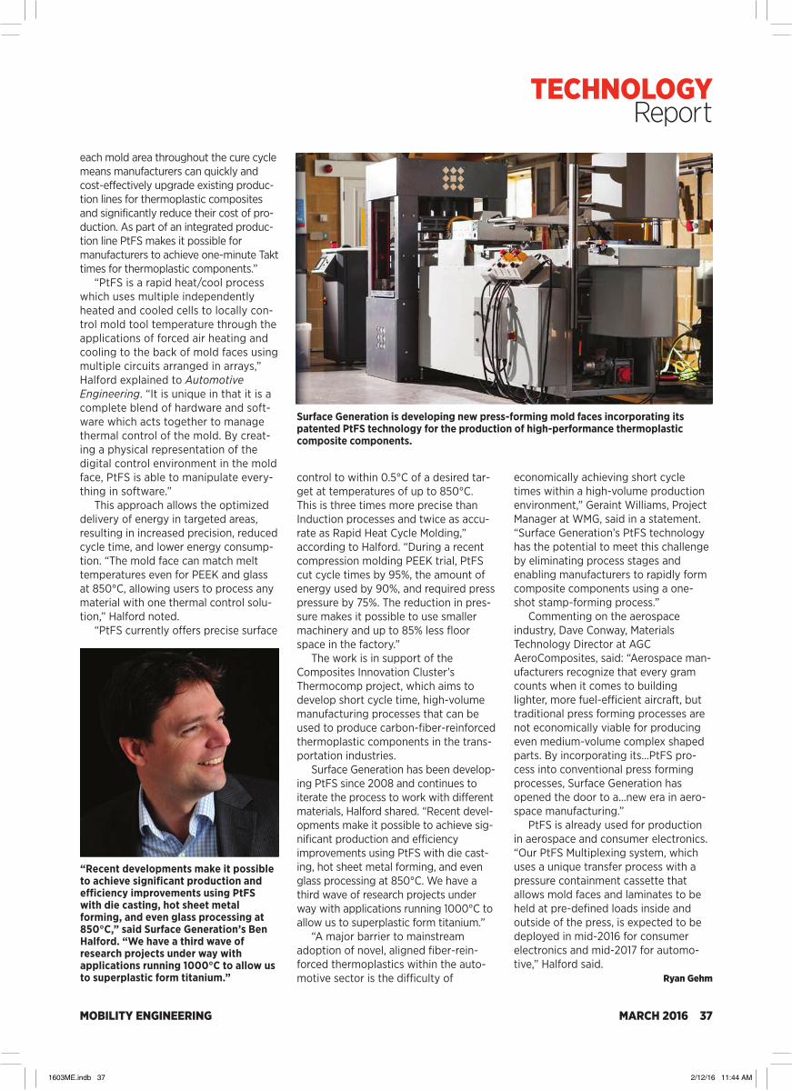
MOBILITY ENGINEERING MARCH 2016 37
each mold area throughout the cure cycle means manufacturers can quickly and cost-effectively upgrade existing produc-tion lines for thermoplastic composites and significantly reduce their cost of pro-duction. As part of an integrated produc-tion line PtFS makes it possible for manufacturers to achieve one-minute Takt times for thermoplastic components.”
“PtFS is a rapid heat/cool process which uses multiple independently heated and cooled cells to locally con-trol mold tool temperature through the applications of forced air heating and cooling to the back of mold faces using multiple circuits arranged in arrays,” Halford explained to Automotive Engineering. “It is unique in that it is a complete blend of hardware and soft-ware which acts together to manage thermal control of the mold. By creat-ing a physical representation of the digital control environment in the mold face, PtFS is able to manipulate every-thing in software.”
This approach allows the optimized delivery of energy in targeted areas, resulting in increased precision, reduced cycle time, and lower energy consump-tion. “The mold face can match melt temperatures even for PEEK and glass at 850°C, allowing users to process any material with one thermal control solu-tion,” Halford noted.
“PtFS currently offers precise surface
control to within 0.5°C of a desired tar-get at temperatures of up to 850°C. This is three times more precise than Induction processes and twice as accu-rate as Rapid Heat Cycle Molding,” according to Halford. “During a recent compression molding PEEK trial, PtFS cut cycle times by 95%, the amount of energy used by 90%, and required press pressure by 75%. The reduction in pres-sure makes it possible to use smaller machinery and up to 85% less floor space in the factory.”
The work is in support of the Composites Innovation Cluster’s Thermocomp project, which aims to develop short cycle time, high-volume manufacturing processes that can be used to produce carbon-fiber-reinforced thermoplastic components in the trans-portation industries.
Surface Generation has been develop-ing PtFS since 2008 and continues to iterate the process to work with different materials, Halford shared. “Recent devel-opments make it possible to achieve sig-nificant production and efficiency improvements using PtFS with die cast-ing, hot sheet metal forming, and even glass processing at 850°C. We have a third wave of research projects under way with applications running 1000°C to allow us to superplastic form titanium.”
“A major barrier to mainstream adoption of novel, aligned fiber-rein-forced thermoplastics within the auto-motive sector is the difficulty of
“Recent developments make it possible to achieve significant production and efficiency improvements using PtFS with die casting, hot sheet metal forming, and even glass processing at 850°C,” said Surface Generation’s Ben Halford. “We have a third wave of research projects under way with applications running 1000°C to allow us to superplastic form titanium.”
Surface Generation is developing new press-forming mold faces incorporating its patented PtFS technology for the production of high-performance thermoplastic composite components.
economically achieving short cycle times within a high-volume production environment,” Geraint Williams, Project Manager at WMG, said in a statement. “Surface Generation’s PtFS technology has the potential to meet this challenge by eliminating process stages and enabling manufacturers to rapidly form composite components using a one-shot stamp-forming process.”
Commenting on the aerospace industry, Dave Conway, Materials Technology Director at AGC AeroComposites, said: “Aerospace man-ufacturers recognize that every gram counts when it comes to building lighter, more fuel-efficient aircraft, but traditional press forming processes are not economically viable for producing even medium-volume complex shaped parts. By incorporating its...PtFS pro-cess into conventional press forming processes, Surface Generation has opened the door to a...new era in aero-space manufacturing.”
PtFS is already used for production in aerospace and consumer electronics. “Our PtFS Multiplexing system, which uses a unique transfer process with a pressure containment cassette that allows mold faces and laminates to be held at pre-defined loads inside and outside of the press, is expected to be deployed in mid-2016 for consumer electronics and mid-2017 for automo-tive,” Halford said.
Ryan Gehm
TECHNOLOGY Report
1603ME.indb 37 2/12/16 11:44 AM
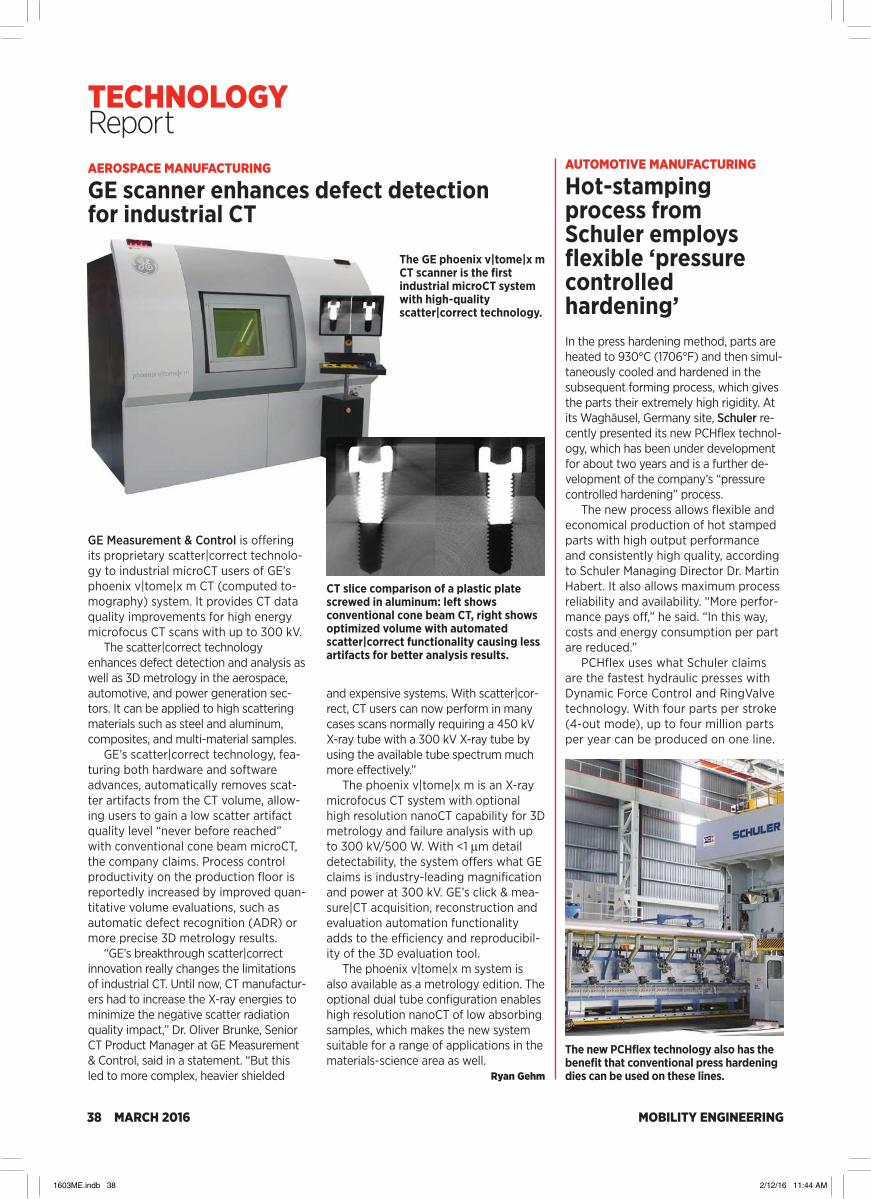
MOBILITY ENGINEERING38 MARCH 2016
AEROSPACE MANUFACTURING
GE scanner enhances defect detection for industrial CT
GE Measurement & Control is offering its proprietary scatter|correct technolo-gy to industrial microCT users of GE’s phoenix v|tome|x m CT (computed to-mography) system. It provides CT data quality improvements for high energy microfocus CT scans with up to 300 kV.
The scatter|correct technology enhances defect detection and analysis as well as 3D metrology in the aerospace, automotive, and power generation sec-tors. It can be applied to high scattering materials such as steel and aluminum, composites, and multi-material samples.
GE’s scatter|correct technology, fea-turing both hardware and software advances, automatically removes scat-ter artifacts from the CT volume, allow-ing users to gain a low scatter artifact quality level “never before reached” with conventional cone beam microCT, the company claims. Process control productivity on the production floor is reportedly increased by improved quan-titative volume evaluations, such as automatic defect recognition (ADR) or more precise 3D metrology results.
“GE’s breakthrough scatter|correct innovation really changes the limitations of industrial CT. Until now, CT manufactur-ers had to increase the X-ray energies to minimize the negative scatter radiation quality impact,” Dr. Oliver Brunke, Senior CT Product Manager at GE Measurement & Control, said in a statement. “But this led to more complex, heavier shielded
and expensive systems. With scatter|cor-rect, CT users can now perform in many cases scans normally requiring a 450 kV X-ray tube with a 300 kV X-ray tube by using the available tube spectrum much more effectively.”
The phoenix v|tome|x m is an X-ray microfocus CT system with optional high resolution nanoCT capability for 3D metrology and failure analysis with up to 300 kV/500 W. With <1 µm detail detectability, the system offers what GE claims is industry-leading magnification and power at 300 kV. GE’s click & mea-sure|CT acquisition, reconstruction and evaluation automation functionality adds to the efficiency and reproducibil-ity of the 3D evaluation tool.
The phoenix v|tome|x m system is also available as a metrology edition. The optional dual tube configuration enables high resolution nanoCT of low absorbing samples, which makes the new system suitable for a range of applications in the materials-science area as well.
Ryan Gehm
The GE phoenix v|tome|x m CT scanner is the first industrial microCT system with high-quality scatter|correct technology.
CT slice comparison of a plastic plate screwed in aluminum: left shows conventional cone beam CT, right shows optimized volume with automated scatter|correct functionality causing less artifacts for better analysis results.
The new PCHflex technology also has the benefit that conventional press hardening dies can be used on these lines.
AUTOMOTIVE MANUFACTURING
Hot-stamping process from Schuler employs flexible ‘pressure controlled hardening’In the press hardening method, parts are heated to 930°C (1706°F) and then simul-taneously cooled and hardened in the subsequent forming process, which gives the parts their extremely high rigidity. At its Waghäusel, Germany site, Schuler re-cently presented its new PCHflex technol-ogy, which has been under development for about two years and is a further de-velopment of the company’s “pressure controlled hardening” process.
The new process allows flexible and economical production of hot stamped parts with high output performance and consistently high quality, according to Schuler Managing Director Dr. Martin Habert. It also allows maximum process reliability and availability. “More perfor-mance pays off,” he said. “In this way, costs and energy consumption per part are reduced.”
PCHflex uses what Schuler claims are the fastest hydraulic presses with Dynamic Force Control and RingValve technology. With four parts per stroke (4-out mode), up to four million parts per year can be produced on one line.
TECHNOLOGY Report
1603ME.indb 38 2/12/16 11:44 AM

MOBILITY ENGINEERING MARCH 2016 39
With its PCH (pressure controlled hardening) technology, Schuler has succeeded in halving cooling times for parts. (All images: Schuler)
By controlling pressure during hard-ening, the necessary press force can be distributed evenly over the part. The flexible bed cushion ensures—within the part and distributed over several parts—a uniformly high contact pressure, result-ing in faster cooling, according to Jens Aspacher, Sales Manager Hot Forming at Schuler. “This ensures a reliable and opti-mized metallurgical transformation pro-cess,” he stated. The cooling time is claimed to be half that of conventional methods, while productivity and part quality are increased.
“The material properties are the same [as with other hot-stamping pro-cesses], but the martensitic transforma-tion becomes more reliable within the part, which leads to higher content of martensite and higher part quality,” Aspacher added.
What makes the PCHflex technology unique, according to Aspacher, is that automotive manufacturers and suppliers are more independent of die and material fluctuations for process reasons; different manufacturing tolerances and sheet thicknesses can be compensated for more easily. “This reduces scrap as well as downtime and idle losses that would otherwise occur due to the reworking of dies, for instance,” he shared.
An additional benefit of the new PCHflex technology is that existing conventional press hardening dies can be used on these lines, he noted. And
conversely, dies designed for PCHflex technology can be used on conven-tional lines.
A U.S. car manufacturer has placed an order with Schuler for four production lines to manufacture lightweight parts using PCHflex technology. Options have been agreed upon for four further lines. The supplier expects PCHflex to be in operation by the beginning of 2017.
“As a systems supplier, Schuler will not only be providing hydraulic presses and automation equipment, but also the roller hearth ovens and dies,” explained Habert. “Our employees will
“Commercial-vehicle manufacturers are also affected by the need to reduce CO2 emissions, which is why they, too, have to make use of lightweight parts with extremely high rigidity. And hot stamping is the most economical way to produce lightweight parts,” said Schuler’s Jens Aspacher.
also be helping launch production in the first few months.”
Is the pressure-controlled process suit-able for applications on on- and off-high-way heavy-duty vehicles? “Absolutely,” said Aspacher. “Commercial-vehicle man-ufacturers are also affected by the need to reduce CO2 emissions, which is why they, too, have to make use of lightweight parts with extremely high rigidity. And hot stamping is the most economical way to produce lightweight parts.”
Paired parts such as left and right of the rocker, A-, B- and C-pillars, or the roof frame are typical applications for the process. “Now, there are more and more roof bows or connector plates under the back seat, for example. More or less all structural parts which do not need to absorb energy in crash situa-tions [are possible],” Aspacher said. “Outer skin parts are not possible because of the rough surface.”
The press-hardening equipment sup-plier expects demand for such technol-ogy to grow in the coming years due to requirements for passenger protection and emissions reduction. In response, the company is planning to open a new Hot Stamping TechCenter at the Group’s main site in Göppingen, Germany, in early 2016. The technical center will serve both as a demonstration center as well as a location for training and research on press hardening.
Ryan Gehm
TECHNOLOGY Report
1603ME.indb 39 2/12/16 11:44 AM
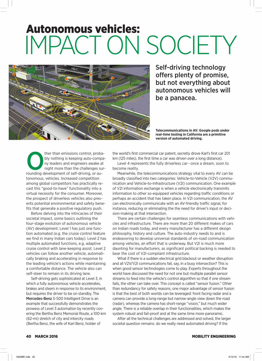
MOBILITY ENGINEERING40 MARCH 2016
Other than emissions control, proba-bly nothing is keeping auto-compa-ny leaders and engineers awake at night more than the challenges sur-
rounding development of self-driving, or au-tonomous, vehicles. Increased competition among global competitors has practically re-cast this “good-to-have” functionality into a virtual necessity for the consumer. Moreover, the prospect of driverless vehicles also pres-ents potential environmental and safety bene-fits that generate a positive regulatory push.
Before delving into the intricacies of their societal impact, some basics outlining the four-stage evolution of autonomous vehicle (AV) development: Level 1 has just one func-tion automated (e.g. the cruise control feature we find in many Indian cars today). Level 2 has multiple automated functions, e.g. adaptive cruise control with lane-keeping assist. Level 2 vehicles can follow another vehicle, automati-cally braking and accelerating in response to the leading vehicle’s actions while maintaining a comfortable distance. The vehicle also can self-steer to remain in its driving lane.
Self-driving gets sophisticated at Level 3, in which a fully autonomous vehicle accelerates, brakes and steers in response to its environment, but requires the driver to be on standby. The Mercedes-Benz S-500 Intelligent Drive is an example that successfully demonstrates the prowess of Level 3 automation by recently cov-ering the Bertha Benz Memorial Route, a 100-km (62-mi) stretch of city and intercity roads (Bertha Benz, the wife of Karl Benz, holder of
Autonomous vehicles:
the world’s first commercial car patent, secretly drove Karl’s first car 201 km (125 miles), the first time a car was driven over a long distance).
Level 4 represents the fully driverless car—once a dream, soon to become reality.
Meanwhile, the telecommunications strategy vital to every AV can be broadly classified into two categories: Vehicle-to-Vehicle (V2V) commu-nication and Vehicle-to-Infrastructure (V2I) communication. One example of V2I information exchange is when a vehicle electronically transmits information to other so-equipped vehicles regarding traffic conditions or perhaps an accident that has taken place. In V2I communication, the AV can electronically communicate with an AV-friendly traffic signal, for instance, reducing or eliminating the the need for driver’s input or deci-sion-making at that intersection.
There are certain challenges for seamless communications with vehi-cles and infrastructure. There are more than 20 different makes of cars on Indian roads today, and every manufacturer has a different design philosophy, history and culture. The auto-industry needs to and is endeavoring to develop universal standards of on-road communication among vehicles, an effort that is underway. But V2I is much more daunting for manufacturers, as significant political backing is needed to bear the cost of V2I-compliant infrastructure.
What if there is a sudden electrical grid blackout or weather disruption and all V2V/V2I communications fail, say, in a busy intersection? This is when good sensor technologies come to play. Experts throughout the world have discussed the need for not one but multiple parallel sensor streams to feed into the vehicle’s control algorithm so that if one stream fails, the other can take over. This concept is called “sensor fusion.” Other than redundancy for safety reasons, one major advantage of sensor fusion is that the best of both worlds can be leveraged: front facing radar and a camera can provide a long-range but narrow-angle view down the road (radar), whereas the camera has short-range “vision,” but much wider angle. There is a reliable overlap in their functionalities, which makes the system robust and fail-proof and at the same time more panoramic.
After all the technical challenges are addressed and solved, the larger societal question remains: do we really need automated driving? If the
Telecommunications in AV: Google pods under real-time testing in California are a primitive version of automated driving.
Self-driving technology offers plenty of promise, but not everything about autonomous vehicles will be a panacea.
IMPACT ON SOCIETY
1603ME.indb 40 2/12/16 11:44 AM

MOBILITY ENGINEERING MARCH 2016 41
AUTOMOTIVE ELECTRONICS FEATURE
answer is yes, then the billion-dollar business question becomes “why, what need does an AV address?” The answer lies in the fact that AVs offer not just release from the often stressful act of driving but also safety. Most road accidents are caused by human error, so in a not-so-distant future of fully autonomous driving, there theoretically could be no accidents at all.
That utopian evolution can be projected to arrive in two stages: first will be a mix of AVs and manually-driven vehicles, progressing to a time when almost all vehicles on the road are AVs. In the initial few years, traf-fic accidents might be reduced only to a certain extent but stress-reduc-tion and fuel-efficiency returns would drastically improve as driving would be more controlled. There would be less-frequent risky maneuvers and fuel-wasting acceleration and deceleration. Enhanced security fea-tures like automatic braking and lane-keeping assist already reduce the chances of collisions and other accidents.
But the advantages of AVs are not just about fuel-efficiency and reduced probability of collision; there are other ways in which the “cost of driving” is reduced with an AV. Most everyone would abhor an hour-long commute to work in bumper-to-bumper traffic, one that sees the work day start with fatigue and frustration. Imagine, instead, reading the newspaper, scheduling meetings for the day and consuming breakfast while “driving” the same one-hour stretch. Would the driver of an AV think it as much a waste of time?
With the reduced cost of driving, there would be an enormous change in the city architecture and planning as well. With proximity not a concern (less of a concern, to be more precise), cities could be spread apart and less dense. City centers would be more efficiently packed and a multitude of parking lots eliminated. Scattered parking lots could be combined into single multi-level mega parking lots, which would free an enormous amount of real estate for other purposes.
The widespread adoption of a driverless car may change the model of automotive manufacturing as it exists today. With the increased potential of car-sharing, an auto company might want to sell its line-up as a service rather than a product. And AVs will lead to change in the auto-insurance industry: accident liability may partially or completely shift from the vehicle owner to the manufacturer. This may be the case, anyway, as the vehicle owner increasingly will have little to do with operating the vehicle—other than perhaps planning a route.
However, just as Achilles had a vulnerability, AVs will not come with-out challenges.
Let us flashback to the opening paragraph that questioned the potential environmental benefits of the AV. In a world of self-driving technology in which every vehicle now comes with a free “lifetime chauffeur,” would a
consumer who might not otherwise have pur-chased a second vehicle, let’s say, now buy that additional vehicle to handle shuttling children to school and other errands? The autonomous-vehi-cle revolution might actually lead to an exponen-tial rise in the number of cars on roads, rather than a decrease. A marginal per-vehicle decrease in fuel consumption enabled by self-driving tech-nology would be vastly overpowered by a rising number of vehicles per capita.
Even if we accept that some better-off fam-ilies might buy more cars, it is also a fact that AVs would make car-sharing much more feasi-ble and affordable. But we already have road transportation available as service today: taxis, Uber and other ride-hailing services. Chauffeur service is quite expensive in the developed regions, so AVs might offer comparative cost advantages, but in India and other less-devel-oped places, driver expense is not that high. Would AV technology in a country like India, where labor is cheap, be of significant cost benefit? And in developed countries, how will the economy respond to the job loss of taxi and ride-share drivers?
It’s inarguable that AVs can be credited with some serious benefits—not just for the consumer but for society as a whole. At the same time, there are certain considerable challenges, making autonomous driving something of a bipolar con-cept. A successful implementation will require global leaders and auto-industry giants to con-join forces to come up with a single solution on the magnitude of E=MC2 or likewise.
This article was written for Mobility Engineering by Surojit Sen
Sensor fusion will be a vital aspect of all autonomous vehicle development.IMPACT ON SOCIETY
1603ME.indb 41 2/12/16 11:44 AM

MOBILITY ENGINEERING42 MARCH 2016
With the crankshaft being one of the key components in engine development, it draws outsized attention from powertrain developers seeking to ascertain its reliability. Crankshaft reliability depends on a number of parame-
ters such as general engine architecture, material property variations and manufacturing process variations.
Reliability is defined as the ability of a system or component to per-form its required functions under stated conditions for a specified period of time. The concept of reliability, however, is quickly evolving from component and engine validation to simulation and verification at the early stages of engine design. Reliable crankshafts provide assured performance and scalable design for future engine families.
Crankshaft reliabilityby integrated design,simulationand testingThis testing method is proven and beneficial for the design and development of the crankshaft and could be applied to other critical engine components, thereby extending to system reliability.
Engine Architecture
1D Simulation / ClassicalComputation
MBD / FEA
Component Testing
Engine Testing
Stress -Strength
Distribution
Reliability Demonstration
Cyclic Speed Irregularity
Engine Speed (RPM)
Angular Fluctuations
Figure 1: Requirements to reliability (R-R) approach for reliability demonstration.
Figure 2: 1-D cranktrain model and its typical output.
MethodologyFigure 1 illustrates the overall reliability meth-odology for crankshaft design. In the current scenario, misperceptions exist among engi-neers as where to begin the design for reliabili-ty (DFR) process—should it be from bench-marking data or engine architecture to validate a reliable design. This paper attempts to clarify the approach required for Requirements to Reliable (R-R) design as shown in Figure 1.
Our study result and approach is based on the stress-strength method, where the design
1603ME.indb 42 2/12/16 11:44 AM

MOBILITY ENGINEERING MARCH 2016 43
AUTOMOTIVE POWERTRAIN FEATURE
is carried out to 99.97% reliability with 90% statistical confidence to prove reliability via component and engine testing.
Engine architecture and simulationThis work explains the advanced engineering approach to the design of a crankshaft from requirements and engine architecture. Engine architecture requirements were 250,000 kilo-meters (155,350 miles) of engineering life, flat torque in a mid-rpm range and best brake specific fuel consumption (BSFC) and fuel effi-ciency (FE) with an engineering target for emissions. Based on that requirement, bore, stroke and other critical engine dimensions were finalized.
Classical computational models were used to arrive at crankshaft critical dimensions and generate a preliminary computer aided design (CAD) model.
1-D simulation tools use inputs from common computations such crankshaft dimensions, balance masses, etc. Typical outputs from the 1-D simulation tool are crank fluctuations, main bearing reactions and crankshaft mass balancing. Figure 2 shows 1-D cranktrain model and its outputs.
Correlation of 1D-simulation results with field measurement was car-ried out to ensure model robustness. The pressure-crank angle inputs for multi body dynamics (MBD) was taken from in-cylinder combustion simulation. Figure 3 shows the correlation of combustion peak pressure simulation and test results.
A Modified Goodman diagram (Figure 4) is plotted from inputs from finite element analysis (FEA) to find design factor of safety.
The objective of MBD is to simulate crankshaft behavior under vary-ing speeds and loads and understand the stress variation for a given Indian Driving Cycle (IDC). The MBD model uses IDC and pres-sure-crank angle as primary inputs separate from geometry inputs from CAD. Joint definitions in MBD are shown in Table 1.
The simulation was run for one full duty cycle and the stress history at the pin center and pin/journal fillets were obtained. Stress history,
Crank Angle (degrees)
P-Θ at 2250 rpm & 0% Load
Gas Pressure
Simulated Data
Test Data
Figure 3: Peak pressure prediction in-cylinder combustion simulation.
Modified Goodman Diagram
Mean/Average Stress (MPa)Al
tern
atin
g/Am
plitu
de S
tress
(MPa
)
600
500
400
300
200
100
0-1000 -800 -600 -400 -200 0 200 400 600 800 1000
GoodMan line
2.Pin fillet
Yield Line
3.Journal fillet
yield-comp
4. Web area
1.Pin Center
0.2% proofstrength330
0.6 * Fatiguestrength
204
2
3
41
-5500.2% proofstrength
550 0.2% proof strength
Ultimate Tensilestrength 950
Figure 4: Sample Modified Goodman Diagram
Figure 5: Typical MBD model for simulation.
TABLE 2: SIMULATION/TESTING - INPUTS & OUTPUTSSIMULATION/TESTING INPUT OUTPUT
Classical computation Engine architecture Critical CAD dimensions
1-D simulation CAD dimensions Crank fluctuations, bearing forces, crank mass balancing
IC engine combustion CAD, flow measurements Peak pressure (Pmax),simulation heat-release rate
FEA / MBD CAD, pressure-crank angle, Stress, strain at pin/journal fillet, bearing reaction forces pin center
Component fatigue Test load cycles/time, No. of cycles to failure,testing Strain gauging strain measurement
Physical testing Test load cycles/time No. of cycles to failure
TABLE 1: MULTIBODY DYNAMICS MODEL - JOINTS DEFINITION
COMPONENT 1 COMPONENT 2 JOINT TYPE
Piston Ground Translation
Piston Piston Pin Fixed
Piston Pin Connecting Rod Revolute
Connecting Rod Crankshaft Revolute
Crankshaft Ground Force component
1603ME.indb 43 2/12/16 11:44 AM

MOBILITY ENGINEERING44 MARCH 2016
StressFatigueStrength
Interference region
AUTOMOTIVE POWERTRAIN FEATURE
along with duty cycle, is used in MSC fatigue software to estimate cycles to failure for the design. Table 2 provides a summary of simula-tion inputs and outputs. Figure 5 shows a typi-cal MBD model bound for simulation.
Component fatigue testCrankshaft fatigue evaluation was done through the resonance bending method. Table 3 gives the test condition summary.
The component validation provided outputs such as stress concentration factor, strains at critical locations, fatigue strength and failure region identification. Magnetic particle inspec-tion was carried out to confirm crack initiation.
Engine validationThe crankshaft was validated through several engine metrics such as the resonance durabili-ty, cyclic durability, piston scuff, high-speed-no-load and deep thermal shock tests.
Accelerated testing was carried out for all durability testing. Tested crankshafts were inspected for wear, surface and sub-surface cracks (via magnetic particle inspection), change in hardness and fatigue strength.
Statistical tools in reliability demonstrationReliability calculations were carried out using in-house tools based on the stress-strength
approach. Stress variation (from FEA) and material strength variation (from testing) are input to the tool. The standard deviation and covari-ance are calculated at 3σ levels.
Interference region in Figure 8 provided the 99.997% reliability with 90% engineering confidence.
SummaryThe stated approach helped to develop crankshaft by requirements-re-liability with due correlation with part development and validation test data. The integration of 1D, MBD & FEA gave a complete understanding of stress distribution. Test Results (fatigue/engine testing) provided strength distribution and failure area with engineering confidence. The reliability tool is capable of understanding variations and mean shift and effectively produce a reliability (≥6ϭ) for the crankshaft. This ap-proach is proven and beneficial for design and development of the crankshaft and could be applied to other critical components, thereby extending to system reliability.
This article was written for Mobility Engineering by Prasanth Balasubramanian, Powertrain System
Engineer, Hindujatech Ltd. and Ravianandan M., FEA Lead Engineer, Hindujatech Ltd.
TABLE 3: FATIGUE TEST PARAMETERSPARAMETER VALUE
Sample Tested 8
Excitation Source electric Shaker @50Hz
Strain Ratio -1
Test Nature HALT (highly accelerated list test)
Strain gauging areas refer figure 6
Front side Rear flange side
4
1 2
5
3
Figure 6: Strain gauge locations in crankshaft.
Figure 7: Crankshaft test setup (courtesy
Ametek & Sumitomo Metal Corp.)
Figure 8: Stress-strength approach for crankshaft reliability.
Crankshaft reliabilityby integrated design,simulation and testing
1603ME.indb 44 2/12/16 11:44 AM

MOBILITY ENGINEERING MARCH 2016 45
Engine history bonus question for 100 points: What technology has been shared by the P-47 Thunderbolt fighter plane, Oldsmobile’s 1962 Jetfire V8, the Saab 99 Turbo, and the 2016 BMW M4 GTS?
Answer: Water injection, a proven technique for raising the knock threshold, enabling a higher compression ratio for more power output over a wide operating range. Water injection is particularly effective in highly boosted engines, hence BMW’s adoption of it in a limited-pro-duction run of M TwinPower 3.0-L Turbo inline six units powering the track-day-focused M4 GTS.
BMW’s engineering logic says that in turbocharged engines, the intake air is heated in the turbo compressor to as much as 160°C (320°F). But the effectiveness of intercoolers in reducing the pressurized intake-air temperature is limited by system size, configuration, and vehicle aerody-namics. So simply increasing boost pressure to raise engine power is not viable, as it would exceed the knock threshold.
Enter water injection where, in the case of the M4 GTS application, a fine mist of H2O is injected at 145 psi (10 bar) by three dedicated
NEW ENGINESHighlighting the design, engineering, and technologies inside some of the most competitive new gasoline and light-duty diesel ICEs.
by Lindsay Brooke, Stuart Birch, Kami Buchholz, and Paul Weissler
injectors into the intake plenum. This reduces the intake air temperature by an additional 27°C (80°F) beyond the intercoolers’ capabil-ity, allowing spark timing to be advanced and more efficient, lower-temperature combus-tion to be realized. The engine is calibrated for minimum 95 RON gasoline.
Water injection adds complexity and cost, as BMW realizes. In the M4, the water injection module consisting of a 1.3 gal plastic water tank, a pump, sensors and valves resides in a compartment under the trunk. Water supply lines connect to the engine’s intake plenum. The quantity of water injected varies depend-ing on load, rpm, and temperature; track-day flogging may require the water tank be topped off at each refueling, while normal street driv-ing extends the interval to about every fifth
2016
BMW’s first production use of water injection in automobiles
reduces the knock threshold in its new twin-turbocharged
3.0 L six. It is also the industry’s first use of the
technology since the 1970s. Note water injectors located
in the intake plenum.
AUTOMOTIVE POWERTRAIN FEATURE
1603ME.indb 45 2/12/16 11:44 AM

MOBILITY ENGINEERING46 MARCH 2016
XXXXXXXXXX
refueling, according to BMW engineers.The BMW M water injection system, devel-
oped in collaboration with Bosch, uses an expanded engine ECU and a unique self-diag-nosis system. If the water tank runs dry, or the system malfunctions, boost pressure and spark timing are adjusted so the engine continues to operate safely. And in everyday use, each time the engine is switched off, the water supply line automatically drains into the tank to prevent icing in freezing temperatures. (The early H2O-injected aero engines used a mixture of water and glycol for anti-icing measures.)
Besides its knock-mitigation capabilities, the BMW M4 GTS engine brims with technol-ogy for reduced mass, greater throttle response, and low friction. Its closed-deck cylinder block is engineered for increased rigidity, enabling higher cylinder pressure. The cylinder bores feature a twin-wire arc-sprayed (“plasma”) coating that reduces weight versus a linered block. The twin tur-bochargers are single-scroll types, and the 24 valves are actuated by Valvetronic variable lift control and Double-VANOS continuously variable camshaft timing. The result is a claimed 493 hp (368 kW) at 6250 rpm, and 442 lb·ft (599 N·m) at 4000-5500 rpm.
Porsche’s 3.0-L turbo Boxer rebellion Porsche joins the downsized-and-boosted trend in 2016, with an all-new turbocharged 3.0-L horizontally-opposed “boxer” six replac-ing naturally-aspirated 3.4-L and 3.8-L engines in the 911 Carrera and Carrera S. Known inter-nally as 9A2, this is an entirely new architec-ture targeting increased efficiency and lower CO2 emissions with added power.
The 3.0-L as fitted to the Carrera gets an
extra 20 hp (15 kW), with peak output now at 365 hp (272 kW). The Carrera S engine also gains 20 hp, for 414 hp (309 kW) total. Peak torque also is increased by 44 lb·ft (60 N·m), to 331 and 368 lb·ft (450 and 500 N·m) on the respective models, available from 1700 to 5000 rpm.
The new boxer uses one BorgWarner turbocharger per cylinder bank. The hotter S version of the 3.0 L features modified turbine com-pressors, a specific exhaust system and tuned engine management. The mono-scroll, fixed-vane turbos use a vacuum-operated wastegate system to manage boost pressure, set at 13 psi (0.9 bar) in the Carrera and 16 psi (1.1 bar) in the Carrera S. Compression ratio on both variants was reduced 12.5:1 to 10.0:1, and both are rev-limited to 7500 rpm.
The Carrera and S will not carry “Turbo” badges; that will remain the province of the super-high-performance 911 GT, according to the com-pany. Besides improved acceleration and top speed, the turbo engine enables the Carrera models to achieve lower fuel consumption and emissions: the S with PDK transmission has a combined figure of 7.7 L/100 km, an improvement of 1.0 L/100 km. Claimed CO2 emissions are 169 g/km for the regular Carrera, 174 g/km for the S.
The move to turbocharging required a new engine airflow system for combustion and intercooling in this industry-unique rear engine appli-cation, with combustion air entering the car body in the center of the rear spoiler and flowing through ducts to the induction manifold and twin intercoolers. The 3.0-L’s Continental-supplied, centrally-located injectors are fed by two fuel pumps, one per cylinder bank, operating
Boosted engine, high compression ratio, and water injection help make BMW’s new street-legal M4 GTS a track-day star. Note complexity of the H2O injection system in the bottom image.
NEW ENGINES2016
1603ME.indb 46 2/12/16 11:44 AM
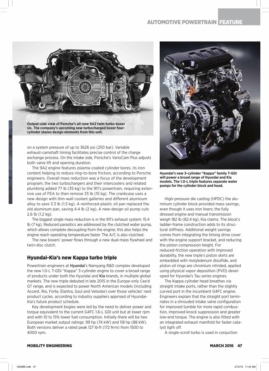
MOBILITY ENGINEERING MARCH 2016 47
on a system pressure of up to 3626 psi (250 bar). Variable exhaust-camshaft timing facilitates precise control of the charge exchange process. On the intake side, Porsche’s VarioCam Plus adjusts both valve lift and opening duration.
The 9A2 engine features plasma-coated cylinder bores, its iron content helping to reduce ring-to-bore friction, according to Porsche engineers. Overall mass reduction was a focus of the development program; the two turbochargers and their intercoolers and related plumbing added 77 lb (35 kg) to the 911’s powertrain, requiring exten-sive use of FEA to then remove 33 lb (15 kg). The crankcase uses a new design with thin-wall coolant galleries and different aluminum alloy to save 3.3 lb (1.5 kg). A reinforced-plastic oil pan replaced the old aluminum pan, saving 4.4 lb (2 kg). A new-design oil pump cuts 2.6 lb (1.2 kg).
The biggest single mass reduction is in the 911’s exhaust system: 15.4 lb (7 kg). Reduced parasitics are addressed by the clutched water pump, which allows complete decoupling from the engine; this also helps the engine reach operating temperature faster. The A/C is also clutched.
The new boxers’ power flows through a new dual-mass flywheel and twin-disc clutch.
Hyundai-Kia’s new Kappa turbo triplePowertrain engineers at Hyundai’s Namyang R&D complex developed the new 1.0-L T-GDi “Kappa” 3-cylinder engine to cover a broad range of products under both the Hyundai and Kia brands, in multiple global markets. The new triple debuted in late 2015 in the Europe-only Cee’d GT range, and is expected to power North American models (including Accent, Rio, Forte, Elantra, Soul and Veloster) over those vehicles’ next product cycles, according to industry suppliers apprised of Hyundai-Kia’s future product schedule.
Key development bogies were led by the need to deliver power and torque equivalent to the current G4FC 1.6-L GDI unit but at lower rpm and with 10 to 15% lower fuel consumption. Initially there will be two European market output ratings: 99 hp (74 kW) and 118 hp (88 kW). Both versions deliver a rated peak 127 lb·ft (172 N·m) from 1500 to 4000 rpm.
High-pressure die casting (HPDC) the alu-minum cylinder block provided mass savings, even though it uses iron liners; the fully dressed engine and manual transmission weigh 182 lb (82.4 kg), Kia claims. The block’s ladder-frame construction adds to its struc-tural stiffness. Additional weight savings comes from integrating the timing drive cover with the engine support bracket, and reducing the piston compression height. For reduced-friction operation with improved durability, the new triple’s piston skirts are embedded with molybdenum disulfide, and piston oil rings are chromium nitrided, applied using physical vapor deposition (PVD) devel-oped for Hyundai’s Tau series engines.
The Kappa cylinder head breathes via straight intake ports, rather than the slightly curved port in the incumbent G4FC engine. Engineers explain that the straight port termi-nates in a shrouded intake valve configuration for improved tumble for more rapid combus-tion, improved knock suppression and greater low-end torque. The engine is also fitted with an integrated exhaust manifold for faster cata-lyst light off.
A single-scroll turbo is used in conjuction
Output-side view of Porsche’s all-new 9A2 twin-turbo boxer six. The company’s upcoming new turbocharged boxer four-cylinder shares design elements from this unit.
Hyundai’s new 3-cylinder “Kappa” family T-GDi will power a broad range of Hyundai and Kia models. The 1.0-L triple features separate water pumps for the cylinder block and head.
AUTOMOTIVE POWERTRAIN FEATURE
1603ME.indb 47 2/12/16 11:44 AM

MOBILITY ENGINEERING48 MARCH 2016
XXXXXXXXXX
with an electrically operated wastegate. Each fuel injector features six laser-bored holes arrayed in a pyramid configuration for opti-mum dispersion in the combustion chamber. The injection systems operates at up to 2900 psi (200 bar).
Two thermostats allow independent cooling of the block and head. The head’s thermostat opens at 190°F (88°C) to avoid detonation, while the block’s opens at 221°F (105°C) to reduce mechanical friction.
GM brings 2.8-L Duramax diesel to midsized trucksThe official EPA fuel economy estimates—31 mpg highway, 22 city, and 25 combined—make the 2016 Chevrolet Colorado and GMC Canyon powered by GM’s 2.8-L Duramax 4-cylinder turbodiesel the most fuel-efficient pickups sold in North America. Automotive Engineering has put many road-test miles on the new midsized diesel trucks, in Michigan and California, and found it’s easy to exceed 30 mpg on a highway trip sans load.
The new engine—part of the trucks’ North American product plan since its inception—produces SAE-rated 181 hp (135 kW) and 369 lb·ft (500 N·m), giving the Colorado/Canyon towing capability of 7600 lb and 7700 lb (3447 and 3492 kg) in their respective 4WD and 2WD variants, topping a number of full-size spark-ignited competitors including the latest Ram 1500 V6 and naturally aspirated Ford F-150 3.5 L V6. The diesel is paired with GM’s 6L-50 6-speed planetary automatic, with
standard 3.42:1 final drive gearing that includes the G80 limited-slip/locking differential.
A descendant of GM’s previous diesel-development relationship with Fiat, the Thailand-built “mini Duramax” carries DNA from VM Motori—it’s a cousin to the VM-sourced diesel briefly available in the Jeep Liberty, and has a 2.5-L variant for global markets. “The team spent more than three years developing the new 2.8 for use in the midsize trucks,” explained Assistant Chief Engineer Scott Yackley. “There was a lot of detail work in not only making the engine emissions compliant, but also able to meet North American customer requirements for smooth and quiet operation.”
The four-cylinder Duramax was launched in 2011, its architecture combining a cast-iron cylinder block and aluminum head, the latter secured with 10 head bolts. A laminated steel-and-aluminum “acoustic” oil pan is part of a comprehensive NVH attenuation package—twin bal-ance shafts; unique fuel injection timing map in the Continental ECU; a centrifugal pendulum absorber (CPA); hydraulic engine mounts; and strategic insulation including three acoustic absorbers on top of the engine—for North America that is quite effective in making the diesel almost invisible to ears inside the cabin.
Yackley noted that engineers relocated the oil pump so it is now driven off of a balance shaft, measurably smoothing the pump’s vibra-tion profile. A segment-first technology he’s proud of is the CPA, inte-grated with the torque converter and supplied by Luk. The CPA, a type of tuned mass absorber, contains a secondary spring mass that, when energized, cancel the diesel’s amplitude of torsional vibrations. CPAs are currently used on BMW and Mercedes automotive diesels, an area in which Luk (part of Schaeffler Group) has deep experience.
The Honeywell M12 EC-5 turbocharger is a variable-geometry
Cutaway of the aluminum DOHC cylinder head of GM’s new 2.8-L Duramax diesel shows injector details, clamping arrangement. (Lindsay Brooke)
Duramax’s robustly engineered balance-shaft module also drives the oil pump. (Lindsay Brooke)
NEW ENGINES2016
1603ME.indb 48 2/12/16 11:44 AM

MOBILITY ENGINEERING MARCH 2016 49
machine operating at 35-40 psi boost pressures under peak loads. It features a new compressor wheel design optimized for performance and low noise, Yackley said. Exhaust exits through a long mega-phone-shaped “venturi-cooled” tailpipe similar to those used on Duramax V8-equipped 2500/3500 trucks. There is no muffler on the diesel Colorado/Canyon, because the truck meets GM’s pass-by noise standards. Yackley noted that sans muffler, the system produces less backpressure downstream of the DPF (diesel particulate filter).
Another segment first is the integrated, driver-selectable exhaust brake system, similar to that used on GM’s HD diesel models. When the exhaust brake is engaged in Cruise mode, algorithms signal the cruise control system to maintain the desired downhill vehicle speed, keeping the driver from having to apply the brakes and exit cruise control to maintain speed. In non-cruise mode, the transmission and the exhaust brake deliver the correct amount of braking to assist in vehicle control, regardless of vehicle load.
A somewhat controversial design/engineering decision is the diesel’s timing belt, rather than a chain, which Yackley claimed is suitably robust for a 150,000 mi (241,000 km) service life before replacement. The choice of a belt has GM diesel fans buzzing on various Internet blogs.
Cold-start was another focus for Yackley’s team. The Duramax employs a ceramic-tip glow plug in each cylinder to pre-heat the com-bustion chamber, along with a larger output starter and bigger-amp-hours battery. A block heater kit is available for extreme-cold conditions.
Fully dressed, the Duramax weighs about 510 lb (231 kg), according to Yackley. With its full emissions suite including cooled EGR module, diesel oxidation cat, SCR, and particulate filter, the diesel option is 250 to 300-lb (113 to 136-kg) heavier than the GM 3.6-L all-aluminum gasoline V6 also available in the trucks, and about 430 lb (195 kg)
heavier than the spark-ignited 2.5-L inline four base engine.
As an integrated package, the 2.8-L Duramax and Colorado/Canyon are impressive despite the diesel’s $3700 option price. Broad torque delivery, a responsive throttle, minimal turbo lag at low rpm, and a nearly perfect match of transmission and final gearing make the trucks unique and desirable, and not just for diesel enthusiasts.
Nissan VR30DETT: new 3.0-L twin turboThe first Nissan twin-turbo V6 to power an Infiniti-brand model debuts in the 2016 Q50 Red Sport 400, a special high-performance sedan aimed at BMW’s M5.
Based on Nissan’s VR-series V6 launched in 3.8-L form on the 2007 GT-R, the new direct-injected engine is designated VR30DETT. It will be available with two per-formance ratings: 400 hp (298 kW) and 350 lb·ft (475 N·m), and 300 hp (224 kW) and 295 lb·ft (400 N·m). Both engines make peak power at 6400 rpm, with peak torque avail-able from 1600-5200 rpm.
The aluminum 60° cylinder block features “square” 86 x 86-mm (3.39-in) bore and stroke dimensions, with thermal-arc-sprayed bores. The technology, also known as “plasma coating,” is claimed to reduce ring-to-bore
The Luk centrifugal pendulum absorber is integrated with the 6L-50 transmission torque converter and helps quell the 4-cylinder Duramax diesel’s vibes.
Nissan’s all-new 3.0-L VR30DETT—the TT stands for twin turbo—is available in two performance ratings and is thus far an Infiniti-only power unit.
AUTOMOTIVE POWERTRAIN FEATURE
1603ME.indb 49 2/12/16 11:44 AM
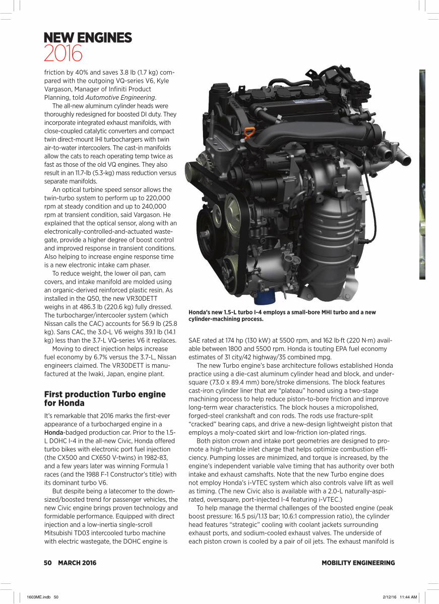
MOBILITY ENGINEERING50 MARCH 2016
XXXXXXXXXX
friction by 40% and saves 3.8 lb (1.7 kg) com-pared with the outgoing VQ-series V6, Kyle Vargason, Manager of Infiniti Product Planning, told Automotive Engineering.
The all-new aluminum cylinder heads were thoroughly redesigned for boosted DI duty. They incorporate integrated exhaust manifolds, with close-coupled catalytic converters and compact twin direct-mount IHI turbochargers with twin air-to-water intercoolers. The cast-in manifolds allow the cats to reach operating temp twice as fast as those of the old VQ engines. They also result in an 11.7-lb (5.3-kg) mass reduction versus separate manifolds.
An optical turbine speed sensor allows the twin-turbo system to perform up to 220,000 rpm at steady condition and up to 240,000 rpm at transient condition, said Vargason. He explained that the optical sensor, along with an electronically-controlled-and-actuated waste-gate, provide a higher degree of boost control and improved response in transient conditions. Also helping to increase engine response time is a new electronic intake cam phaser.
To reduce weight, the lower oil pan, cam covers, and intake manifold are molded using an organic-derived reinforced plastic resin. As installed in the Q50, the new VR30DETT weighs in at 486.3 lb (220.6 kg) fully dressed. The turbocharger/intercooler system (which Nissan calls the CAC) accounts for 56.9 lb (25.8 kg). Sans CAC, the 3.0-L V6 weighs 39.1 lb (14.1 kg) less than the 3.7-L VQ-series V6 it replaces.
Moving to direct injection helps increase fuel economy by 6.7% versus the 3.7-L, Nissan engineers claimed. The VR30DETT is manu-factured at the Iwaki, Japan, engine plant.
First production Turbo engine for HondaIt’s remarkable that 2016 marks the first-ever appearance of a turbocharged engine in a Honda-badged production car. Prior to the 1.5-L DOHC I-4 in the all-new Civic, Honda offered turbo bikes with electronic port fuel injection (the CX500 and CX650 V-twins) in 1982-83, and a few years later was winning Formula 1 races (and the 1988 F-1 Constructor’s title) with its dominant turbo V6.
But despite being a latecomer to the down-sized/boosted trend for passenger vehicles, the new Civic engine brings proven technology and formidable performance. Equipped with direct injection and a low-inertia single-scroll Mitsubishi TD03 intercooled turbo machine with electric wastegate, the DOHC engine is
SAE rated at 174 hp (130 kW) at 5500 rpm, and 162 lb·ft (220 N·m) avail-able between 1800 and 5500 rpm. Honda is touting EPA fuel economy estimates of 31 city/42 highway/35 combined mpg.
The new Turbo engine’s base architecture follows established Honda practice using a die-cast aluminum cylinder head and block, and under-square (73.0 x 89.4 mm) bore/stroke dimensions. The block features cast-iron cylinder liner that are “plateau” honed using a two-stage machining process to help reduce piston-to-bore friction and improve long-term wear characteristics. The block houses a micropolished, forged-steel crankshaft and con rods. The rods use fracture-split “cracked” bearing caps, and drive a new-design lightweight piston that employs a moly-coated skirt and low-friction ion-plated rings.
Both piston crown and intake port geometries are designed to pro-mote a high-tumble inlet charge that helps optimize combustion effi-ciency. Pumping losses are minimized, and torque is increased, by the engine’s independent variable valve timing that has authority over both intake and exhaust camshafts. Note that the new Turbo engine does not employ Honda’s i-VTEC system which also controls valve lift as well as timing. (The new Civic also is available with a 2.0-L naturally-aspi-rated, oversquare, port-injected I-4 featuring i-VTEC.)
To help manage the thermal challenges of the boosted engine (peak boost pressure: 16.5 psi/1.13 bar; 10.6:1 compression ratio), the cylinder head features “strategic” cooling with coolant jackets surrounding exhaust ports, and sodium-cooled exhaust valves. The underside of each piston crown is cooled by a pair of oil jets. The exhaust manifold is
Honda’s new 1.5-L turbo I-4 employs a small-bore MHI turbo and a new cylinder-machining process.
NEW ENGINES2016
1603ME.indb 50 2/12/16 11:44 AM

MOBILITY ENGINEERING MARCH 2016 51
cast integrally with the head, following the industry trend toward faster catalyst light off.
To optimize space in the compact, 4-valve combustion chamber M12-type spark plugs rather than the larger M14 type are used.
A low-friction, silent-chain drives the two camshafts—both of them hollow for reduced reciprocating mass. And low-friction oil seals are used throughout.
Turbo Civic models offer a Honda-engineered CVT that was developed from the unit used in 4-cylinder Accord models, but with a final-drive ratio that is 4.7% higher, for reduced engine rpm during highway operation. Uniquely, Honda’s CVT uses a twin-damper torque converter to help reduce turbocharger lag during acceleration. In a series of test drives of the 2016 Civic Turbo, Automotive Engineering found performance to be far superior to that of the 2.0-L model, and about on par with Honda’s 2.4-L engine, with linear power delivery through the 5500-rpm torque peak.
FCA adds water-cooled EGR to Pentastar V6FCA’s “Pentastar” 3.6-L gasoline V6 receives significant upgrades for 2016 that enable the broadly-used engine to gain efficiency, while posi-tioning it for a move to direct injection and advanced aftertreatment strategies at a future date.
The addition of new liquid-cooled EGR, a new two-step variable valve lift system on the intake side, and increased compression ratio to 11.3:1 (from 10.2), enable the V6 to deliver 6% greater fuel economy on the combined U.S. FTP along with a 5.0 hp/3.7 kW increase (to 295 hp/220 kW) and 15% more torque under 3000 rpm, according to Bob Lee, FCA North America Vice President of Engine, Powertrain and
Electrified Propulsion.The new water-cooled EGR, typically a fea-
ture of heavy diesels, reduces exhaust-gas tem-perature from 650°C to 130°C (1202°F to 266°F), Lee told Automotive Engineering. The reduced gas temperature helps enable the higher compression ratio by suppressing knock at higher loads. And the EGR in itself delivers a 0.8% improvement in fuel economy and low NOx emissions, he said. High-tumble intake ports and shrouded valves further enhance fuel, air, and exhaust mixing.
The new valvetrain (https://youtu.be/YZtqCq9TXZg) is situated in a new, lighter thin-wall cylinder head. It is activated by oil pressure under control by four solenoid valves—two for each cylinder head. Each roller cam follower incorporates a high-lift section held in place by a spring-loaded lockpin; the high-lift mode (10.3 mm/0.41 in) is the default.
On acceleration, a solenoid valve opens and oil pressure pushes the lockpin, releasing the high-lift follower section. It pivots down on a bushing, and the roller follower runs on low-valve-lift (5.75 mm/0.23 in) cam lobes, in which the engine stays through to the 2800-rpm switchover point.
The switchover reduces pumping work and contributes to improved combustion, which delivers both the modest increase in horse-power and boosts fuel economy by 2.7%, Lee explained. New eight-hole fuel injectors (vs. the previous four-hole), high-tumble intake ports and 100-mJ ignition coils combine for a claimed 1% fuel economy improvement. The 2016 engine’s VVT authority has been increased to a range of 70°, vs. 50° previously. (VVT on the old Chrysler-designed engine was part of the control system that eliminated the need for EGR.) And the system expands the operating range of the carryover idle stop/restart system—a real-world fuel economy benefit that also gives FCA a CAFE credit.
These upgrades added 13 lb (6 kg) to the engine’s overall mass, the EGR and variable lift system accounting for over 7.5 lb/3.4 kg. Along with the lighter head castings, weight reduction actions include a lighter (by almost 2 lb/0.9 kg) and stronger block; smaller oil pan; the new two-piece intake manifold, and even details like nodular cast-iron main bearing caps vs. the old powder cast iron—a 0.8-lb (0.4-kg) savings. On average the upgraded Pentastar V6 weighs 4 lb/1.8 kg less than its predecessor.
Various friction-reducing improvements, including slimmer crankshaft journals and crankpins, improve fuel economy 1%.
FCA’s significantly upgraded 3.6-L Pentastar V6 now includes a liquid-cooled EGR module. (Paul Weissler)
AUTOMOTIVE POWERTRAIN FEATURE
1603ME.indb 51 2/12/16 11:44 AM
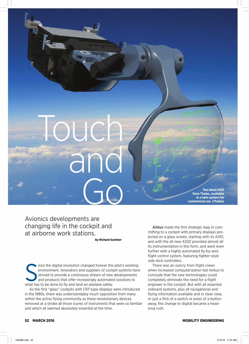
MOBILITY ENGINEERING52 MARCH 2016
Since the digital revolution changed forever the pilot’s working environment, innovators and suppliers of cockpit systems have strived to provide a continuous stream of new developments and products that offer increasingly automated solutions to
what has to be done to fly and land an airplane safely. As the first “glass” cockpits with CRT-type displays were introduced
in the 1980s, there was understandably much opposition from many within the active flying community as these revolutionary devices removed at a stroke all those scores of instruments that were so familiar and which all seemed absolutely essential at the time.
Airbus made the first strategic leap in com-mitting to a cockpit with primary displays pro-jected on a glass screen, starting with its A310, and with the all-new A320 provided almost all its instrumentation in this form, and went even further with a highly automated fly-by-wire flight control system, featuring fighter-style side stick controllers.
There was an outcry from flight crews when increased computerization led Airbus to conclude that the new technologies could completely eliminate the need for a flight engineer in the cockpit. But with all essential onboard systems, plus all navigational and flying information available and in clear view, or just a flick of a switch or press of a button away, the change to digital became a head-long rush.
Touch and Go
Avionics developments are changing life in the cockpit and at airborne work stations.
by Richard Gardner
The latest HUDfrom Thales, available
in a twin system for commercial use. (Thales)
1603ME.indb 52 2/12/16 11:44 AM

MOBILITY ENGINEERING MARCH 2016 53
Human FactorsFollowing recent high-profile aircraft losses and other flight incidents, some critics have suggested that industry has made the profes-sion of flying too easy and too relaxed. When an aircraft’s key integrated flight data inputs are supposedly protected by five separate computer systems and a series of fail-safe flight control recovery modes, and yet the crew become confused as the computers be-come overwhelmed by conflicting information returns, there is a need for quick and decisive, but appropriate, corrective action.
Human factors are often the key to analyz-ing what has gone wrong and so the onward march of cockpit automation and component miniaturization, which has led to even very small executive jets and general aviation air-craft being fitted with highly automated dis-plays, now has to seriously consider if enough scope is being allowed for pilots to actually fly the aircraft and not just assume it will fly itself—even though it usually does!
All the leading cockpit system suppliers are now well advanced in designing and bringing to market what appear to be approaching the ultimate in user-friendly dis-plays. Even quite recently some of these developments have looked more like sci-ence-fiction inventions, but the availability of new materials and new manufacturing pro-cesses that can embed touch-sensitive switches and controls into large wraparound transparent panels, have been made possible by adopting much technology that has come from the gaming and CGI sector as well as the Grand Prix car racing sector.
Making these applications robust enough for safe everyday use in life-critical aviation use is more time-consuming from a regulatory angle, as ease of use has to be balanced by sufficient tactile interaction between man and machine so that there is no loss of authority or confidence on the part of the pilot, who ulti-mately must remain in charge.
HUD AdvancesThe day when civil air passengers will fly in commercial aircraft that have no human pilots on board could happen very soon, technically, but it won’t, as no airline, and few customers, would want to take the risk. However, an iden-tical flight, with two crew in the cockpit as monitors and who could take control in an emergency, will probably be the most likely way forward, with little difference in delivery and presentation to today’s operations. Truly
disruptive advanced avionics technology will more likely appear first in the military sector.
One development that certainly has its origins in military aviation but which has now taken pilot situational awareness (SA) to new lev-els in the commercial market is the head-up display (HUD). Certified by Airbus this year, Thales has now introduced a twin HUD configura-tion that enables all the projected information to be seen by both pilots simultaneously.
With eyes focused outside, viewing the presentation of the flight-path, acceleration, visual glideslope angle, and the runway aim point, both crew members can achieve greater precision and SA at all times and can interact with one another with the same information during the most critical phases of the flight, especially in bad weather and low light conditions.
In late September, Thales announced that its latest dual HUD system had been selected by China Southern Airlines for use aboard its 30 new A320s. It is a significant order as it’s the first dual HUD to be ordered by a Chinese airline and the country’s Civil Aviation Administration of China has made it mandatory for all Chinese regis-tered aircraft to be equipped with HUDs.
As China’s skies become more congested, HUDs are fast becoming a mainstay for pilots and the country is leading the world in adopting this technology. China has progressed in under two decades from operating some of the world’s oldest airline fleets, flying largely Russian-designed aircraft, to having some of the world’s youngest air-line fleets, flying the latest models from Airbus, Boeing, Bombardier, and Embraer. As well as placing orders for thousands of new Western aircraft, China is developing its own indigenous aircraft and in due course will no doubt design and build more of its own avionics sys-tems in place of buying Western products.
Helmet-Mounted Display CaseTaking the avionics progress story on the SA theme back into the mili-tary sector, the latest developments go beyond HUDs with ever more sophisticated helmet-mounted displays (HMDs). Recently BAE Systems
Current standard of airline cockpit—the latest Boeing 787-900. (Richard Gardner)
FEATUREAVIONICS
1603ME.indb 53 2/12/16 11:44 AM

MOBILITY ENGINEERING54 MARCH 2016
presented its latest, fifth-generation HMD, the Striker II, which incorpo-rates features that were developed to give pilots flying aircraft such as the F-35 and Typhoon a comprehensive, game-changing capability.
The F-35 is presently unique in new combat aircraft in so far as it doesn’t have a HUD but depends on an HMD to provide all the key tar-get and flying cues and data ahead of the pilot’s normal vision. During the F-35’s lengthy development phase BAE’s Striker was used as an interim alternative while the incumbent supplier solved image vibration issues. In the meantime the Striker has been proven operationally in use with Typhoon and Gripen fighter aircraft and has now been enhanced by making it an all-digital solution. In addition the helmet has been fit-ted with an integral night vision camera.
The key to exploiting HMD usage in modern combat aircraft is to give the pilot minimal interference or restrictions in operation, while remaining lightweight and comfortable. This is easier described than solved as such a system has to not only provide crystal clear imagery
under all environmental conditions, by day or night, but must not result in creating any blind spots or causing extra strain on the neck and upper torso.
The new Striker II enables the HMD to show imagery from any source and adds new levels of functionality. As well as projecting night vision imagery and standard weap-ons-aiming and flight symbology, the digital architecture allows a zooming function and the ability to present picture-within-picture imagery and even images from external (off-board) sensors that could aid the pilot in tar-get identification. This new comprehensive digital capability can incorporate sensor mix-ing to increase SA significantly, and this work is under active development.
Although the HMD is aimed primarily at use onboard fighters and attack helicopters, the system architecture is adaptable to allow it to be integrated into almost any aircraft. An ana-log converter has been developed so the hel-met can be compatible with older systems as well. The addition of an embedded night vision camera replaces the traditional night vision goggles (NVGs) that are clipped onto a helmet in front of the visor.
With NVGs the pilot’s ability to look around from the cockpit is usually restricted and they also upset the natural mass balance of the hel-met assembly. If a pilot wears NVGs for some time then this can cause neck fatigue as well as leading to restrictions on the g-limits being imposed on the aircraft, not a good feature with combat agility an important requirement for all military fast jets.
On the Striker II helmet the night vision function can be switched on or off through a hands-on throttle and stick control. Trials and feedback from operations indicate that this new function will be particularly valuable at dawn or dusk when a pilot may have some difficulty deciding whether visibility is better with or without the night vision imagery. Another benefit from the new helmet is an advanced head-tracker system that supple-ments the aircraft’s optical tracker. This gives increased tracking accuracy and continues to track the helmet in positions in which some of the optical tracking is lost.
Multi-Mission FunctionalityThe evolution of digital avionics is taking many other paths in addition to revolutioniz-ing the pilot’s cockpit. A good example is the new functionality that can be applied to the displays and controls needed aboard
The Thales AMASCOS Multi-Mission display console with touchscreens and integrated target identification system. (Thales)
Touch and Go
Cockpit display of the future? ODICIS wraparound touchscreen. (Richard Gardner)
1603ME.indb 54 2/12/16 11:44 AM

MOBILITY ENGINEERING MARCH 2016 55
AVIONICS FEATURE
Close up of an AMASCOS display.
multi-mission aircraft. The traditional interior of a multi-engine military sensor platform air-craft has rows of display consoles, each faced by an operator who is allocated specialist tasks collecting, searching for or analyzing data that is streamed into the aircraft.
On aircraft such as the Boeing E-3 Sentry or other electronic communications and sig-nals intelligence platforms, the specialist crews onboard can number around 30 and have bespoke display stations with opera-tional managers keeping the data flows mov-ing and helping to set priorities. So much data can be collected on these missions that infor-mation overload is a real challenge. Although automated data filtration systems can narrow down some of the input so operators includ-ing signals specialists can focus on mission priorities or unusual data, it is highly skilled personnel who ultimately identify, track, and deal with suspect information and then dis-tribute it accordingly.
In the case of maritime patrol and surveil-lance air platforms, the aircraft cabins are also filled by displays and operator desks. Major defense system companies, such as Raytheon, Northrop Grumman, L-3, Boeing, Lockheed Martin, Thales, and Selex ES are all engaged in the development and supply of integrated mission systems for specialist air platforms. Thales has just introduced AMASCOS, a new airborne mission system for maritime and ground surveillance aircraft that may have a similar design impact to that which accompa-nied the first Airbus glass cockpit.
The main feature that sets AMASCOS apart in a very competitive market is the innovative operator screen display configuration, which is particularly user-friendly, thanks to easy-to-learn interactive touchscreens, which are part of a flexible networked integrated system. It makes maximum use of the latest display technologies and is linked to the latest gener-ation of sensors, including radar, laser, and electro-optical systems and is built around a tactical command system.
With its modular architecture, the network centric system can be configured to optimize the crew task sharing for either a lightweight version for simple surveillance tasks (such as coastal or border patrol in a small twin turbo-prop platform) right up to full-function anti-submarine or surface warfare versions (for an MPA aircraft such as P-8 or P-3 size platform), with typically up to five consoles controlling radar, IFF, EO/IR sensors, electronic intelligence, acoustics, magnetic anomaly
detection, datalinks, sonobuoys, and weapons. This formula allows the system to be integrated onto an optimized
platform for customer requirements, offering a wide range of multi-mission capabilities. The operator workload is kept to efficient levels as a result of the high level of system automation. This includes data fusion, identification, and classification. There is a large data base in support of sensors with both an onboard library and access through secure datalinks to additional library databases.
All the data available can be shared between single or multiple oper-ators as needed, and the touchscreen layout allows “saved” tracking information and situational maps and radar pictures to be continuously updated in real time with sub-displays dragged across to another dis-play so the operator can investigate or carry out actions with the maxi-mum awareness of all relevant information in front of him or her, and without having to look away to operate another screen and its controls. The operational picture can thus be as simple or as complex as needs demand. The compact design of the displays and their utility enables a smaller platform aircraft, with a smaller number of crews, to carry out the mission with no loss of capability.
This new system is not the only product on the market, but as state-of-the-art avionics for maximizing exploitation of the new technologies while keeping volume, crew demands, and costs affordable, it shows the way ahead. The old convention of operating many different surveil-lance aircraft types in small numbers for specialist roles is becoming unaffordable and very demanding on training infrastructure. Introducing more flexible multi-mission aircraft that are adaptable to different ISTAR (intelligence, surveillance, targeting, and reconnais-sance) tasks is now a more practical solution, thanks to the availability of avionics solutions that allow fewer to do more with less.
1603ME.indb 55 2/12/16 11:44 AM

MOBILITY ENGINEERING56 MARCH 2016
Single LobeCamshaft
CDA SRFF
DFHLA
Valve Retainerand Keepers
Valve Spring
Valve Guide
Valve
Valve Seat
Bearing Axle
Lost Motion Springs
SwitchingPressure Port
Lash CompensatorPressure Port
ECU
Oil Control Valve(OCV)
Engine OilPump
Cylinder deactivation (CDA) is an effective method to fine-tune engine displacement for maximum output and improve fuel economy by adjusting the number of active cylinders in com-bustion engines.
A switching roller finger follower (SRFF) is an economic solution for CDA that minimizes changes and preserves the overall width, height, or length of dual overhead cam (DOHC) engines. The SRFF is a mechani-cally actuated device that is hydraulically controlled using engine oil. A CDA SRFF provides the flexibility of either transferring or suppressing the camshaft movement to the valves influencing the engine perfor-mance and fuel economy by reducing the pumping losses.
The fuel economy benefits of CDA technology are estimated to be between 2-14%, depending on engine displacement and the number of cylinders that are deactivated. Typical fuel economy gains are 3-6% for six- and eight-cylinder engines. The improvements in fuel economy are possible by reducing the pumping losses when the engine operates in partial load conditions.
Researchers from Eaton recently studied the performance and durability of a CDA SRFF system that meets the reliability require-ments for gasoline automotive engines. Of most importance, this technology—which provides a means for aftertreatment temperature management and fuel economy benefits—is scalable and can be applied to light-, medium-, and heavy-duty applications for gasoline, diesel, and natural gas engines.
Extensive tests were conducted to demonstrate the dynamic stability
at high engine speeds and the system capacity of switching between high and low engine dis-placement within one camshaft revolution. The system durability was demonstrated with high and low engine speeds, various oil tempera-tures, mode switching, and abuse tests, meet-ing the end of life criteria in wear and function.
CDA system descriptionSeveral CDA systems exist today, each custom-ized for a specific valvetrain architecture. The CDA design during the Eaton research project was configured for DOHC engines, in which a SRFF was used along with a single lobe cam-shaft for each of the deactivated valves.
The system included two single lobe cam-shafts, four CDA SRFFs (two SRFFs for intake and two for exhaust valves), four dual-feed hydraulic lash adjusters (DFHLAs), one oil con-trol valve (OCV), and four sets of the valve sub-system that include valve retainers, keepers, valve springs, valve guides, valves, and seats.
The camshaft for the CDA SRFF is very simi-lar to camshafts used on traditional DOHC engines. The difference is that the camshaft
IMPROVING HEAVY-DUTY ENGINE COMPONENT EFFICIENCIES
Schematic showing the complete system for deactivating one
cylinder in a double overhead cam (DOHC) engine.
Cylinder deactivation can improve fuel economy by using a reduced number of cylinders that operate at higher loads and thermal efficiency, while other cylinders are turned off, when the engine operates at partial load conditions. A switching roller finger follower is one of the technologies that help make it work.
1603ME.indb 56 2/12/16 11:44 AM
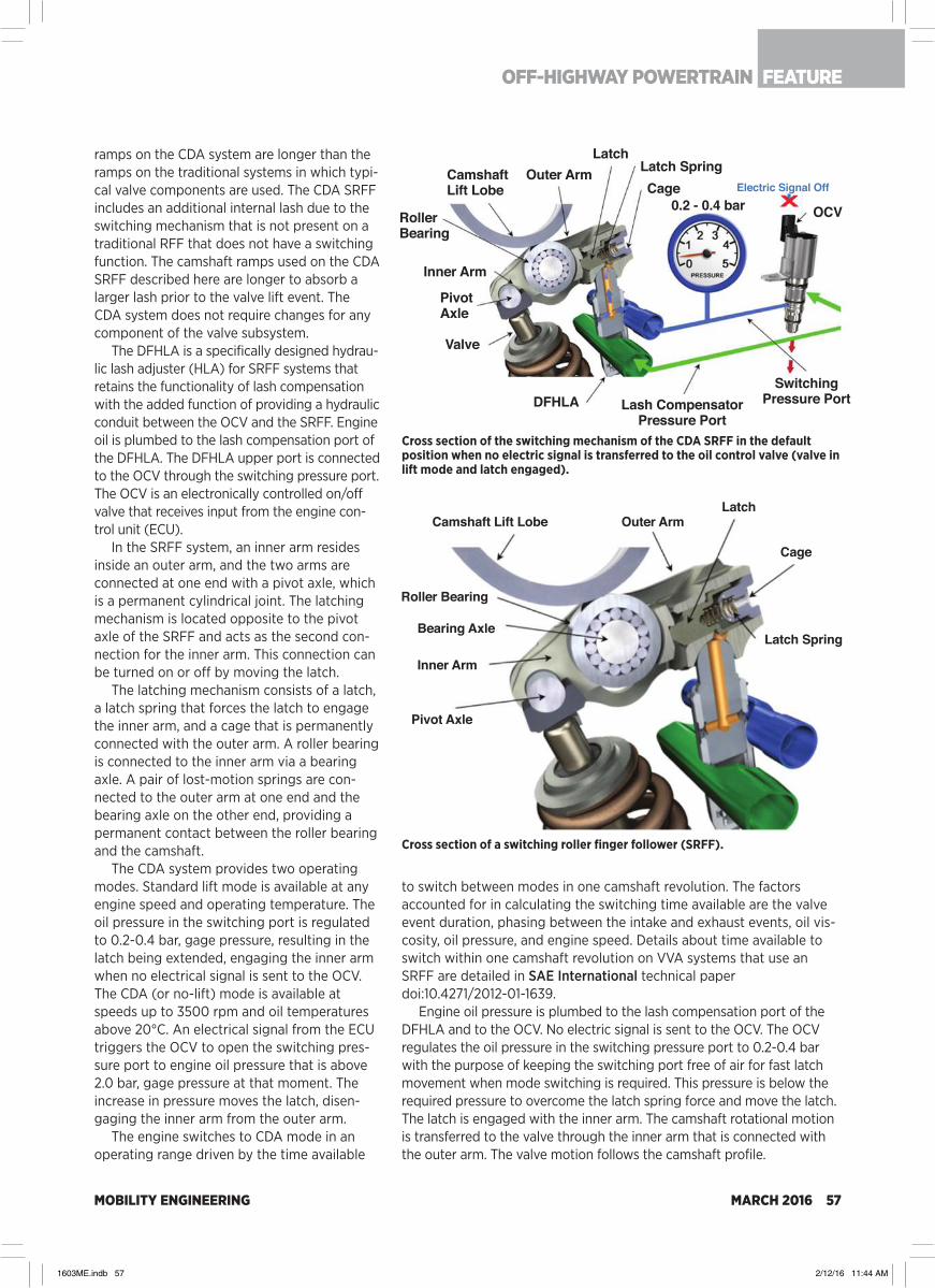
MOBILITY ENGINEERING MARCH 2016 57
ramps on the CDA system are longer than the ramps on the traditional systems in which typi-cal valve components are used. The CDA SRFF includes an additional internal lash due to the switching mechanism that is not present on a traditional RFF that does not have a switching function. The camshaft ramps used on the CDA SRFF described here are longer to absorb a larger lash prior to the valve lift event. The CDA system does not require changes for any component of the valve subsystem.
The DFHLA is a specifically designed hydrau-lic lash adjuster (HLA) for SRFF systems that retains the functionality of lash compensation with the added function of providing a hydraulic conduit between the OCV and the SRFF. Engine oil is plumbed to the lash compensation port of the DFHLA. The DFHLA upper port is connected to the OCV through the switching pressure port. The OCV is an electronically controlled on/off valve that receives input from the engine con-trol unit (ECU).
In the SRFF system, an inner arm resides inside an outer arm, and the two arms are connected at one end with a pivot axle, which is a permanent cylindrical joint. The latching mechanism is located opposite to the pivot axle of the SRFF and acts as the second con-nection for the inner arm. This connection can be turned on or off by moving the latch.
The latching mechanism consists of a latch, a latch spring that forces the latch to engage the inner arm, and a cage that is permanently connected with the outer arm. A roller bearing is connected to the inner arm via a bearing axle. A pair of lost-motion springs are con-nected to the outer arm at one end and the bearing axle on the other end, providing a permanent contact between the roller bearing and the camshaft.
The CDA system provides two operating modes. Standard lift mode is available at any engine speed and operating temperature. The oil pressure in the switching port is regulated to 0.2-0.4 bar, gage pressure, resulting in the latch being extended, engaging the inner arm when no electrical signal is sent to the OCV. The CDA (or no-lift) mode is available at speeds up to 3500 rpm and oil temperatures above 20°C. An electrical signal from the ECU triggers the OCV to open the switching pres-sure port to engine oil pressure that is above 2.0 bar, gage pressure at that moment. The increase in pressure moves the latch, disen-gaging the inner arm from the outer arm.
The engine switches to CDA mode in an operating range driven by the time available
to switch between modes in one camshaft revolution. The factors accounted for in calculating the switching time available are the valve event duration, phasing between the intake and exhaust events, oil vis-cosity, oil pressure, and engine speed. Details about time available to switch within one camshaft revolution on VVA systems that use an SRFF are detailed in SAE International technical paper doi:10.4271/2012-01-1639.
Engine oil pressure is plumbed to the lash compensation port of the DFHLA and to the OCV. No electric signal is sent to the OCV. The OCV regulates the oil pressure in the switching pressure port to 0.2-0.4 bar with the purpose of keeping the switching port free of air for fast latch movement when mode switching is required. This pressure is below the required pressure to overcome the latch spring force and move the latch. The latch is engaged with the inner arm. The camshaft rotational motion is transferred to the valve through the inner arm that is connected with the outer arm. The valve motion follows the camshaft profile.
Camshaft Lift Lobe
Roller Bearing
Bearing Axle
Inner Arm
Pivot Axle
Outer ArmLatch
Cage
Latch Spring
CamshaftLift Lobe
Outer ArmLatch
Latch SpringCage
0.2 - 0.4 barElectric Signal Off
OCVRollerBearing
Inner Arm
PivotAxle
Valve
DFHLA Lash CompensatorPressure Port
SwitchingPressure Port
Cross section of a switching roller finger follower (SRFF).
Cross section of the switching mechanism of the CDA SRFF in the default position when no electric signal is transferred to the oil control valve (valve in lift mode and latch engaged).
FEATUREOFF-HIGHWAY POWERTRAIN
1603ME.indb 57 2/12/16 11:44 AM

MOBILITY ENGINEERING58 MARCH 2016
During the no-lift mode, an electric signal from the ECU energizes the solenoid inside the OCV, opening the switching pressure port to the engine oil pressure. A minimum of 2.0 bar oil pressure is needed to overcome the latch spring. The increase in pressure moves the latch to the retracted position, disengaging the inner arm. The inner arm and the outer arm remain connected at the pivot axle.
The absence of the secondary connection between the two components
results in the camshaft rotational motion being transferred to the inner arm, which pivots around the axle and no camshaft motion is transferred to the valve, resulting in the valve remaining seated.
Engine life testingQuality Function Deployment (QFD) method-ology was used to understand the connection between the engine performance and durabili-ty requirements to SRFF targets for design, performance, durability, and reliability.
The CDA SRFF was divided into four pri-mary subsystems: fatigue, wear-out, switch-ing mechanism, and lost-motion. Each of the four subsystems was investigated to deter-mine the appropriate life targets equivalent to 200,000 mi.
The 200,000 mi target was converted into a number of events that each subsystem would encounter over its lifetime. The number of valve events equivalent to 200,000 mi engine life is more than 300 million. This number was calcu-lated based on a series of duty cycle scenarios.
Valvetrain component wear was accelerated by increasing the engine speed to reduce the test time. A proprietary high-speed durability test cycle was utilized to establish valvetrain wear that is equivalent to 330 million valve events while only requiring a fraction of the test time.
An aggressive target of 15 switching events (lift to deactivation and back to lift again) per mile was established to ensure a robust design. The resulting target was 3 million switching events for the life of the engine. The lost-mo-tion system life target was defined by a high-end user, which provided a conservative target.
The resultant life target was approximately 160 million lost-motion cycles. The SRFF must withstand several abuse events such as critical shifts (unintentional switches from lift mode to deactivation partway through a lift event) and high-speed excursions at speeds above the designed operating range over the course of 200,000 mi.
A target of 5000 critical shifts was set during the development of the CDA SRFF, a conservative approach considering the low fre-quency of critical shift occurrences. Excursions of five consecutive 10 second bursts were con-sidered as the target for the over-speed test when in lift mode. The system was additionally tested to twice the rated lost-motion speed for a total of 10 million cycles to protect the engine in case of an SRFF being in CDA mode uninten-tionally for an extended time.
Valvetrain lash is a key end-of-life measure-able for tests performed on the CDA SRFF. The
Camshaft on Base Circle
Outer Arm
Latch Latch Spring
SwitchingPressure Port
Electric Signal On
> 2 bar
Roller Bearing
Inner Arm
Pivot Axle
Lash CompensatorPressure Port
LatchLatch Spring
The CDA, or no-lift mode, is illustrated here (valve in CDA mode and latch disengaged).
The durability and performance tests were conducted on two motored engine fixtures: a V-6 and an inline four-cylinder. The V-6 fixture was used for performance verification and extreme limit testing. The four-cylinder engine (shown with camshaft cover removed) was used for subsystem testing and accelerated aging.
IMPROVING HEAVY-DUTY ENGINE COMPONENT EFFICIENCIES
1603ME.indb 58 2/12/16 11:44 AM
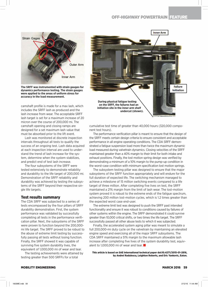
MOBILITY ENGINEERING MARCH 2016 59
camshaft profile is made for a max lash, which includes the SRFF lash as produced and the lash increase from wear. The acceptable SRFF lash target is set for a maximum increase of 20 micron over the course of 200,000 mi. The camshaft opening and closing ramps are designed for a set maximum lash value that must be absorbed prior to the lift event.
Lash was monitored at discrete inspection intervals throughout all tests to qualify the success of an ongoing test. Lash data acquired at each inspection interval are used to under-stand the trend of lash increase for the sys-tem, determine when the system stabilizes, and predict end of test lash increase.
The four subsystems of the SRFF were tested extensively to demonstrate reliability and durability to the life target of 200,000 mi. Demonstration of the SRFF reliability and durability was achieved by testing the subsys-tems of the SRFF beyond their respective sin-gle life targets.
Test results summaryThe CDA SRFF was subjected to a series of tests encompassed by the four pillars of SRFF durability demonstration. First, the system performance was validated by successfully completing all tests in the performance verifi-cation pillar. Next, the subsystems of the SRFF were proven to function beyond the 200,000-mi life target. The SRFF proved to be robust to the abuse of extreme limit testing by success-fully passing all tests without losing function. Finally, the SRFF showed it was capable of surviving five system durability lives, the equivalent of 1,000,000 mi of wear and tear.
The testing achievements were attained by testing greater than 500 SRFFs for a total
cumulative test time of greater than 40,000 hours (320,000 compo-nent test hours).
The performance verification pillar is meant to ensure that the design of the SRFF meets certain design criteria to ensure consistent and acceptable performance in all engine operating conditions. The CDA SRFF demon-strated a fatigue suspension load more than twice the maximum dynamic load measured during valvetrain dynamics. Closing velocities of the SRFF maintained greater than a 40% margin to their limit for both intake and exhaust positions. Finally, the lost motion spring design was verified by demonstrating a minimum of a 10% margin to the pump-up condition in the worst-case condition with minimum specification lost motion springs.
The subsystem testing pillar was designed to ensure that the major subsystems of the SRFF function appropriately and will endure for the full duration of expected life. The switching mechanism managed to achieve a milestone of 15 million switching events compared to a life target of three million. After completing five lives on test, the SRFF maintained a 21% margin from the limit of lash wear. The lost-motion system proved it is robust to the extreme ends of the fatigue spectrum, achieving 200 million lost-motion cycles, which is 1.2 times greater than the expected worst case end-user.
The extreme limit test was designed to push the SRFF past intended functionality and ensure it was robust to conditions caused by failures of other systems within the engine. The SRFF demonstrated it could survive greater than 10,000 critical shifts, or two times the life target. The SRFF successfully passed all other abuse tests to which it was subjected.
Finally, the accelerated system aging pillar was meant to simulate a full 200,000-mi duty cycle on the valvetrain by maintaining an elevated engine speed and exercising all of the major SRFF subsystems. The CDA SRFF maintained a 51% margin to the maximum allowable lash increase after completing five lives of the system durability test, equiv-alent to 1,000,000 mi of wear and tear.
This article is based on SAE International technical paper doi:10.4271/2015-01-2816, by Andrei Radulescu, Leighton Roberts, and Eric Yankovic, Eaton.
The SRFF was instrumented with strain gauges for dynamics performance testing. The strain gauges were applied to the areas of uniform stress for accuracy in the load measurement.
During physical fatigue testing on the SRFF, the failures had an
initiation site in the inner arm shelf undercut (shown).
FEATUREOFF-HIGHWAY POWERTRAIN
1603ME.indb 59 2/12/16 11:44 AM

MOBILITY ENGINEERING60 MARCH 2016
GlobalVEHICLESBUDD-e concept forecasts what VW zero-emission van could be in 2019
At the 2016 CES in Las Vegas, Volkswagen attempted to focus atten-tion away from its diesel engine emis-sions challenge by providing a glimpse into its electric future with an all-electric BUDD-e minivan concept. It would be the first model based on a new compa-ny “technology matrix” for electric vehi-cles called MEB, short for Modular Electric Drive Kit.
Advantages of the MEB promised by VW include spacious interiors and the smallest possible traffic footprint; greater agility, acceleration, and maneu-verability; distinct design identity thanks to new proportion and styling possibilities; and cost-effective access to e-mobility, accompanied by long ranges to match today’s gasoline-pow-ered cars. Better MEB packaging means that the HVAC system, for instance, can be completely integrated in the front end of the van, allowing for bigger and better filters and better acoustics due to a reduction in fan noise.
The concept van is 181.0 in (4597 mm) long, 76.4 in (1940 mm) wide, and 72.2 in (1835 mm) tall, putting it between Volkswagen’s Touran and Multivan T6 vans in terms of length, although the
concept is wider than both. A relatively long wheelbase of 124.1 in (3151 mm) results in very short overhangs.
BUDD-e has electric four-wheel drive with a front motor producing 100 kW and the rear 125 kW. The 92.4 kW·h bat-tery pack enables a theoretical range of up to 233 mi (375 km) in U.S. EPA esti-mated “real-world driving” or 533 km (331 mi) in the more optimistic Euro NEDC test. Theoretical top speed is 112 mph (180 km/h) and from 0 to 60 mph (0-97 km/h) acceleration is 6.9 s.
The flat battery pack, integrated into almost the entire vehicle floor, supplies two electric motors for all-wheel-drive capability, the one in front producing 100 kW and 200 N·m (148 lb·ft) and the rear 125 kW and 290 N·m (214 lb·ft). The battery can be charged by plug or induction, with 150 kW DC enabling an 80% charge fill in about 30 min.
The concept is designed with the option to be driven autonomously. Automated driving “will be part of our everyday lives and will change mobility completely. Volkswagen has a lot of ideas how to use these cutting-edge technologies and bring them to our cus-tomers,” said Dr. Herbert Diess,
Chairman of the Volkswagen Passenger Cars brand, who gave a keynote address on the evening before CES opened its doors to the public.
One of those ideas is behind a strate-gic partnership with Mobileye, announced at the CES, that involves image-processing and swarm-data technology. The central focus of the joint venture is camera-based real-time image processing technology that—in conjunction with highly precise digi-talized maps—is the key to autonomous driving, according to the partners.
“Digital representation of the real world in real time will play a key role in automated driving,” said Diess.
One of the goals of the joint venture, exclusively for Europe, will be to develop intelligent surroundings-monitoring technologies. Mobileye optical sensor systems will be used in the front cameras of future VW products to continually improve what are known as car-sur-roundings maps. Once a large number of vehicles are equipped with this technol-ogy, more precise real-time information can be generated to better serve the entire automated vehicle population.
VW says that by around 2019, when
Dr. Herbert Diess, Chairman of the Volkswagen Passenger Cars brand, introduced the BUDD-e electric van concept in the lead up to the CES.
1603ME.indb 60 2/12/16 11:44 AM
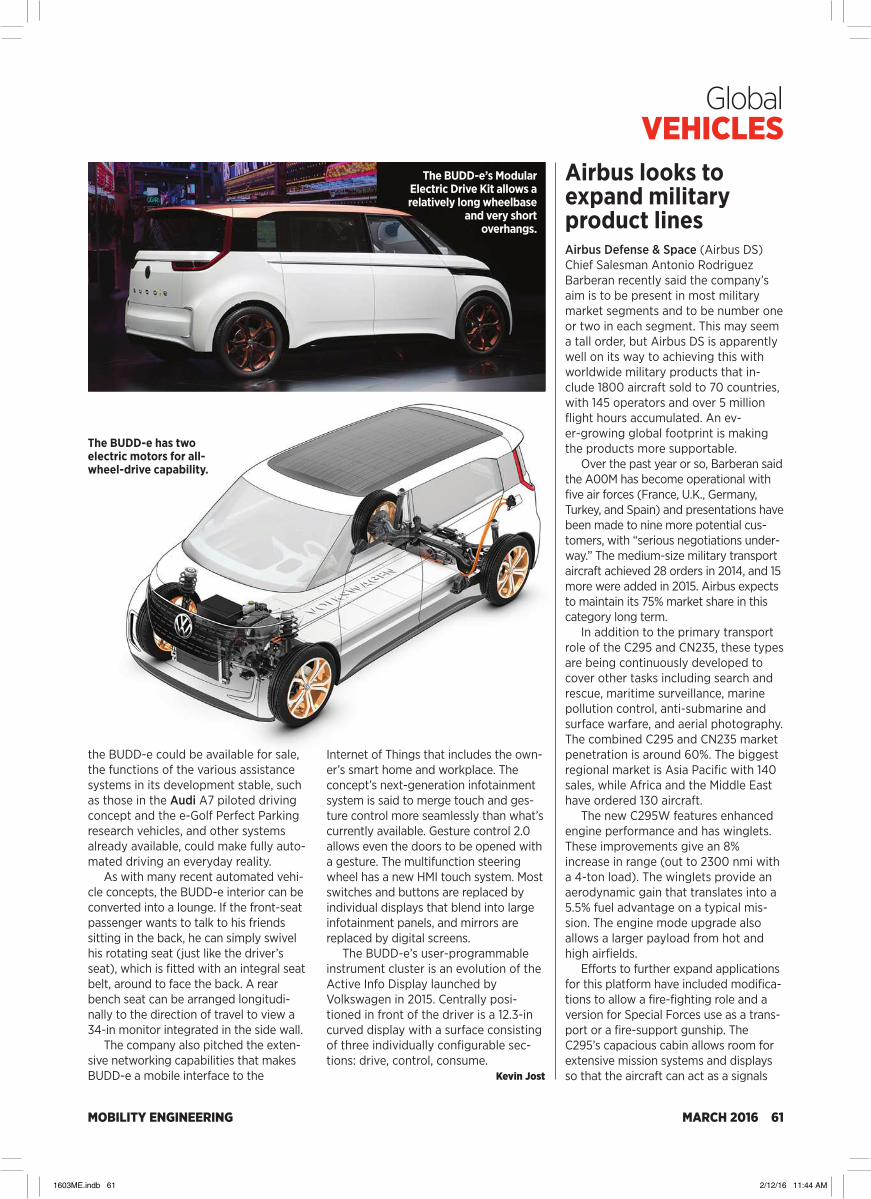
MOBILITY ENGINEERING MARCH 2016 61
Global VEHICLES
the BUDD-e could be available for sale, the functions of the various assistance systems in its development stable, such as those in the Audi A7 piloted driving concept and the e-Golf Perfect Parking research vehicles, and other systems already available, could make fully auto-mated driving an everyday reality.
As with many recent automated vehi-cle concepts, the BUDD-e interior can be converted into a lounge. If the front-seat passenger wants to talk to his friends sitting in the back, he can simply swivel his rotating seat (just like the driver’s seat), which is fitted with an integral seat belt, around to face the back. A rear bench seat can be arranged longitudi-nally to the direction of travel to view a 34-in monitor integrated in the side wall.
The company also pitched the exten-sive networking capabilities that makes BUDD-e a mobile interface to the
Internet of Things that includes the own-er’s smart home and workplace. The concept’s next-generation infotainment system is said to merge touch and ges-ture control more seamlessly than what’s currently available. Gesture control 2.0 allows even the doors to be opened with a gesture. The multifunction steering wheel has a new HMI touch system. Most switches and buttons are replaced by individual displays that blend into large infotainment panels, and mirrors are replaced by digital screens.
The BUDD-e’s user-programmable instrument cluster is an evolution of the Active Info Display launched by Volkswagen in 2015. Centrally posi-tioned in front of the driver is a 12.3-in curved display with a surface consisting of three individually configurable sec-tions: drive, control, consume.
Kevin Jost
The BUDD-e’s Modular Electric Drive Kit allows a relatively long wheelbase
and very short overhangs.
The BUDD-e has two electric motors for all-wheel-drive capability.
Airbus looks to expand military product linesAirbus Defense & Space (Airbus DS) Chief Salesman Antonio Rodriguez Barberan recently said the company’s aim is to be present in most military market segments and to be number one or two in each segment. This may seem a tall order, but Airbus DS is apparently well on its way to achieving this with worldwide military products that in-clude 1800 aircraft sold to 70 countries, with 145 operators and over 5 million flight hours accumulated. An ev-er-growing global footprint is making the products more supportable.
Over the past year or so, Barberan said the A00M has become operational with five air forces (France, U.K., Germany, Turkey, and Spain) and presentations have been made to nine more potential cus-tomers, with “serious negotiations under-way.” The medium-size military transport aircraft achieved 28 orders in 2014, and 15 more were added in 2015. Airbus expects to maintain its 75% market share in this category long term.
In addition to the primary transport role of the C295 and CN235, these types are being continuously developed to cover other tasks including search and rescue, maritime surveillance, marine pollution control, anti-submarine and surface warfare, and aerial photography. The combined C295 and CN235 market penetration is around 60%. The biggest regional market is Asia Pacific with 140 sales, while Africa and the Middle East have ordered 130 aircraft.
The new C295W features enhanced engine performance and has winglets. These improvements give an 8% increase in range (out to 2300 nmi with a 4-ton load). The winglets provide an aerodynamic gain that translates into a 5.5% fuel advantage on a typical mis-sion. The engine mode upgrade also allows a larger payload from hot and high airfields.
Efforts to further expand applications for this platform have included modifica-tions to allow a fire-fighting role and a version for Special Forces use as a trans-port or a fire-support gunship. The C295’s capacious cabin allows room for extensive mission systems and displays so that the aircraft can act as a signals
1603ME.indb 61 2/12/16 11:44 AM

MOBILITY ENGINEERING62 MARCH 2016
Global VEHICLES
intelligence or ground surveillance plat-form, with specialist sensors and multiple target tracking radar, with communica-tions intercept and jamming equipment.
Modifications to give the C295 more weapons capability in the Maritime Patrol (MPA) and anti-submarine (ASW) roles is underway so that air-launched homing torpedoes and air-to-surface missiles can be carried. The C295 and CN235 can both be given a cost-effec-tive MPA or SAR role as they feature high maneuverability at low levels above the sea surface, combined with an endurance of up to 11 hours. The U.S. Coast Guard uses a large fleet of CN235s for law enforcement, border patrols, and para-rescue operations.
Special large size bubble windows give excellent visual coverage for crew mem-bers, while electrooptical video cam-eras, including IR, allow all-weather and night operations.
Palletized ISR mission systems can be provided for the C295 MPA/ASW so that the aircraft can be used for trans-port duties when not required for ISR or MPA duties. If required to provide elec-tronic surveillance, onboard ELINT/COMINT analysis or electronic counter-measures can also be supplied in a very compact package.
Israel’s ELTA has supplied a fourth-generation AESA radar, which has been trialed atop a C295 in an aero-dynamic rotating dome for the detection
In addition to the primary transport role of the C295 (Chilean aircraft shown) and
CN235, these types are being continuously improved to cover other tasks including
search and rescue, maritime surveillance, marine pollution control, anti-submarine
and surface warfare, and aerial photography. New roles being developed
include ISTAR/EW, signals intelligence, fire-fighting, airborne early warning, and a
gunship fire-support role. (Airbus DS)
of multiple small and fast targets, giving 360˚ coverage. For the ground surveil-lance task, the C295 can carry high-res-olution SAR/GMTI radar arrays and an EO/IR target designation turret, ESM, ELINT, and COMINT. It would seem that Airbus is keen to exploit every possible combination of ISR and EW mission roles that can carried aboard its C295 and CN235 aircraft.
It’s been suggested that close air support would be an ideal role for the C295, which could deploy parachutists and supplies and also carry underwing weapons and stores. However, the com-pany’s future planning is already look-ing beyond the C295 platform.
Richard Gardner
A400Ms are shown during mission prep on the flightline. Airbus DS was known previously as Airbus Military but it now also includes other defense businesses of the former EADS, which have combined and been re-packaged. (Richard Gardner)
1603ME.indb 62 2/12/16 11:44 AM

AGC AeroComposites ............................ 36Airbus ..........................................................52Airbus Defense & Space ........................ 61Alfa Romeo .................................................17Altair ............................................................33Altia ..............................................................25Amazon.......................................................25American Trucking Associations ........ 64Ametek ......................................................44Android .........................................................4Ansys .......................................................6, 15Apple .............................................................4ARAI...............................................................6ARAI Academy ......................................... 14Assystem .....................................................12Audi.............................................................. 61Aurora Flight Sciences .......................... 36Automotive Skills Development
Council ................................................... 14BAE Systems .............................................53BASF ............................................................32BMW ....................................................45, 49Boeing .........................................................53Bombardier ................................................53BorgWarner .............................................. 46Bosch ..................................................... 4, 46B.S. Abdur Rahman University ............ 16BYD ...............................................................21Caterpillar ...............................................6, 15CFM ..............................................................22Chevrolet .............................................. 4, 48China Southern Airlines .........................53Chrysler ....................................................... 51CIT Engineering Institute ........................12Civil Aviation Administration
of China .................................................53College of Engineering, Pune ......... 10, 14Continental .......................................... 4, 48Continental Technical Centre India ......12Corning ...................................................... 28Cummins ................................................6, 15Cummins India .......................................... 13Daimler .........................................................12Dantal Hydraulics ..................................... 18Dassault ........................................................8DC Design .................................................. 13Delphi Thermal ........................................ 26
Desch Systems ...........................................21Dowty ..........................................................22Eaton ........................................ 6, 15, 25, 56Eaton Technologies ................................. 13Electric Drive Transportation
Association ............................................21Elektrobit ....................................................25ELTA ............................................................ 62Embraer ......................................................53EPA ....................................................... 26, 48Faraday Future ...........................................4FCA .............................................................. 51Ferrari ...........................................................17Fiat .............................................................. 48Ford ............................................... 28, 32, 48Freightliner ............................................... 64GE ..................................................................12GE Aviation ................................................22GE Measurement & Control ................. 38General Motors ..............................4, 21, 48Geo Technology ....................................... 19Gestamp .................................................... 30Gillig ..............................................................21GMC ............................................................ 48GM Ventures ...............................................21Gordon Murray Design ........................... 19Guru Nanak Dev Engineering College,
Ludhiana ............................................... 10Harman .........................................................4Hindujatech ..............................................44Honda ..................................................30, 50Honeywell.................................................. 48HydraForce .................................................17HydraForce India .......................................17Hyundai ...................................................... 47ICAT ...............................................................8IEEE IAS ........................................................6Infiniti ......................................................... 49Inmarsat ..................................................... 24Insurance Institute for Highway
Safety .....................................................33Intelsat ....................................................... 24International ............................................. 64Jazeera Airways ...................................... 24Jeep ............................................................ 48John Deere ...................................... 6, 13, 14Kalasalingam University ........................ 10
Kia .........................................................27, 47Komatsu......................................................35KTH Royal Institute of Technology .... 34L-3 ................................................................55Lockheed Martin ......................................55Lovely Professional University ...............8Lufthansa................................................... 24Luk ............................................................... 48Magna Exteriors .......................................32Magneti Marelli ......................................... 18Magneti Marelli Powertrain India......... 18Mahindra & Mahindra ..................10, 14, 17Mahindra Research Valley ..................... 10Mahle .......................................................... 26Maruti Suzuki ........................................8, 18Maserati .......................................................17MathWorks .................................................35Mercedes-Benz ........................................40Michelin ........................................................21Mitsubishi .................................................. 20Mobileye ....................................................60MSC Software ...........................................35Multimatic ................................................. 29National Safety Council .........................33Navigant Research ...................................21Navistar ...................................................... 64New Flyer ....................................................21Nissan .................................................. 27, 49Northrop Grumman.................................55Nova Bus .....................................................21Oldsmobile ................................................ 45Panasonic Avionics ................................. 24Peugeot .......................................................17PGW ............................................................ 28Pincar............................................................17Pininfarina ...................................................17Porsche ...................................................... 46Proterra ........................................................21PSNA College of Engg. & Tech ............ 10PTC ...........................................................6, 15Quest Global...............................................12Ram ............................................................. 48Raytheon ............................................. 31, 55Rockwell Collins ................................ 17, 24Roush Industries, AVL .............................21Saab ............................................................ 45SABIC ..........................................................27
SAE .............................................................. 48SAEINDIA ......................6, 10, 12, 13, 14, 16SAE International ....6, 20, 23, 26, 33, 48, 57SAEISS.............................................10, 14, 16SAENIS ..........................................................8Sant Longowal Institute of
Engineering and Technology .......... 10Schaeffler Group ..................................... 48Schuler ....................................................... 38SEA...............................................................33Selex ES ......................................................55ServoControls & Hydraulics India ........ 18Shell ............................................................. 19Siemens ........................................................8Simulia.........................................................33Skogforsk .................................................. 34Society of Plastics Engineers ...............32SRM University ...................................10, 14Stratasys .................................................... 36Studio Gavari............................................ 28Sumitomo Metal ......................................44Surface Generation ................................. 36Suzuki Motor ............................................. 18TAFE ............................................................ 10Tata Motors ......................................... 18, 26TCS ................................................................12Tech Mahindra ............................................17Tesla ...............................................................4Textron Aviation .......................................22Thales ..........................................................53TTControl ....................................................25TVS ................................................................12UCLA ........................................................... 31University of Brunswick .........................27University of Maryland .......................... 26University of Warwick ........................... 36U.S. Marines ...............................................22Varroc ......................................................6, 15Visteon ........................................................ 10VM Motori .................................................. 48Volkswagen ...................................4, 27, 60Volvo ............................................................ 18WalMart ......................................................25Wind River .................................................23WMG ........................................................... 36Yamaha ...................................................... 20ZF ...................................................................4
Allegro Microsystems Inc. .........................................................................7 ............................... http://www.allegromicro.com/camp1254
Altair Engineering India Pvt Ltd. .............................................................5 .................................................... www.altairhyperworks.in/aoc
AR RF/Microwave Instrumentation contact for India .......................9 ...................................................... www.arworld.us/EMCsource ........................................................................................................................................................................................................ www.complus.in
Borg Warner ......................................................................................Cover 3 ............................................................................. borgwarner.com
COMSOL Inc. .................................................................................... Cover 4 .....................................................................................comsol.co.in
Hindustan University.................................................................................. 11 ............................................................. www.hindustanuniv.ac.in
SAINT-GOBAIN .................................................................................Cover 2 ......................................................... makingabigdifference.com ..........................................................................................................................................................................www.bearings.saint-gobain.com
Smalley Steel Ring Company ...................................................................3 ..................................................................................... smalley.com
COMPANIES MENTIONED
AD INDEX
MOBILITY ENGINEERING MARCH 2016 63
1603ME.indb 63 2/12/16 11:44 AM

MOBILITY ENGINEERING64 MARCH 2016
Q&A
“I view the truck almost like an iPhone, in that it’s got all these modules on it—on your iPhone we call them apps,” said Navistar CIO Terry Kline.
Connectivity a core pillar at NavistarNavistar announced last year its plans to offer over-the-air (OTA) reprogramming of engine control modules in 2016 for International trucks powered by its N9, N10, and N13 propri-etary engines. This technology joins the company’s al-ready-in-service OnCommand Connection tool as part of its overall connectivity strategy. OTA reprogramming can be per-formed at the customer’s facility over a secure Wi-Fi connec-tion. Future advancements include expanding to other soft-ware modules on the truck like transmissions and chassis, ac-cording to Terry Kline, Senior Vice President and Chief Information Officer at Navistar Inc. Kline recently spoke with SAE Magazines about the company’s vehicle connectivity plans and its current solutions. Read the full transcript at http://articles.sae.org/14551/.
What is Navistar’s connected vehicle strategy?It’s one of the core pillars of our corporate strategy to the Board of Directors; a cornerstone of what we’re investing in and moving forward. The connected vehicle strategy is a key enabler to some of the other strategies like “up time,” mean-ing that the trucks are running and moving down the road.
We’ve got OnCommand Connection as one of our corner-stones, and it basically is a diagnostic tool that’s an open sys-tem, open architecture, that works with and across all the telematics providers…We’ve got about 160,000 vehicles tied to that system today that we’re reading data from and able to do everything from health reports to repair maps—given these codes from the truck that means you need these parts, this kind of technician, and this bay capability. Based off these codes you can drive 1500 more miles but don’t drive 1501. So we know what’s going to happen to that truck and we’ve been able with OCC to take repair and maintenance, which averages 15 cents a mile according to ATA (American Trucking Associations) and some others, down to 2 to 3 cents by doing predictive maintenance, predictive analytics on when things need to be done vs. doing them the traditional way; this is
with customers that we’re actively working with [who have] fleets of 200, 300 trucks.
This year, probably one of the biggest things coming out is what we call ‘smart routing.’ When your truck throws a code or throws a set of codes, we’ll know where you’re at, what the urgency of that repair is, what parts are necessary, and we would actually allow our dealers to offer up their services to you. It’s not just about what’s the price going to be but ‘when can I get my truck back,’ because one of your trucks is sitting idle.
What’s the idea behind OnCommand’s open architecture?The 160,000 trucks we’ve got on OnCommand, it’s really im-portant to know that more than 50% of those aren’t our trucks, they are competitors’ trucks. And that’s important for a couple of reasons. One, if you own a fleet of trucks, it’s not likely you’re going to own one brand. So we give that fleet owner one place to shop for this type of data, whether they own an International brand, or they own a Freightliner. We’re pretty proud of the fact that we’re open, and we believe we’re unique in that we accept other brands into the solution. Why would we do that? Well, we believe everybody that owns a truck is a potential future customer, and whether that’s to-morrow at the service department buying parts, or that’s the next time they buy a new truck.
As you can imagine we’re getting tons of data; it’s like hav-ing 160,000 test trucks on the road. So whenever we have a ‘what if,’ we generally have a fleet of trucks we can look at to study that [scenario]. It’s been invaluable to increase the qual-ity of our vehicles by looking at these trucks and how they’re performing, or even help customers to understand that the way they’re using the truck is not how it was engineered. In the trucking business, trucks are highly customized; they’re highly designed for [specific] applications—a truck built to have a cement mixer put on the back is much different than a long-haul truck. So maybe people aren’t using these trucks the way they were engineered. We’re starting to notice those things and we can reach out and help; sometimes it’s as easy as reprogramming the shifting patterns of the truck.
How does over-the-air reprogramming fit in? It’s another key piece of our strategy, and we believe it’s unique in the truck space. Obviously people are doing over-the-air programming in other spaces—I’m sure you’ve got a smart phone; it gets programmed over the air all the time. But especially in the heavy trucking industry that we play in, we believe we’re first to market...We’ve got it running in our plants right now, reprogramming trucks. We’ve got it in pilot at some of our dealers and at some of our big customers. And as you would imagine, we’re using it heavily on our own captured fleet.
What’s the goal with OTA reprogramming?Engines are first. I view the truck almost like an iPhone, in that it’s got all these modules on it—on your iPhone we call them apps. On a truck we call them engine control modules, trans-missions have software, brake systems, etc. We want to get to where we program and have the ability to reflash all these devices that have software on them remotely, wirelessly.
Ryan Gehm
1603ME.indb 64 2/12/16 11:44 AM

ME BorgWarner Ad 0316.qxp_Mobility FP 1/28/16 5:17 PM Page 1
1603ME.indb 3 2/12/16 11:44 AM

NOW AVAILABLE
© Copyright 2015 COMSOL. COMSOL, COMSOL Multiphysics, Capture the Concept, COMSOL Desktop, COMSOL Server , LiveLink, and Simulation for Everyone are either registered trademarks or trademarks of COMSOL AB. All other trademarks are the property of their respective owners, and COMSOL AB and its subsidiaries and products are not affiliated with, endorsed by, sponsored by, or supported by those trademark owners. For a list of such trademark owners, see www.comsol.com/trademarks
COMSOL Multiphysics® and its Application Builder provide you with tools to easily design a custom interface for your multiphysics applications. Use COMSOL Server™ to distribute your apps to colleagues and customers worldwide.
To learn about simulation apps, visit comsol.co.in.
From Model to App to Server BRING SIMULATION TO EVERYONE
MODEL WITH COMSOL MULTIPHYSICS®
BUILD SIMULATION APPS
SHARE WITH COMSOL SERVER™
ME COMSOL Ad 1215.qxp_Mobility FP 11/4/15 10:49 AM Page 1
1603ME.indb 4 2/12/16 11:44 AM