Embed Size (px)
Citation preview
OL-27282-05
C H A P T E R 25
Mobile Unified CommunicationsRevised: April 30, 2013; OL-27282-05
Mobile Unified Communications solutions and applications provide the ability to deliver features and functionality of the enterprise IP communications environment to mobile workers wherever they might be. With mobile Unified Communications solutions, mobile users can handle business calls on a multitude of devices and access enterprise applications whether moving around the office building, between office buildings, or between geographic locations outside the enterprise. Mobile Unified Communications solutions provide mobile workers with persistent reachability and improved productivity as they move between, and work at, a variety of locations.
Unified Communications mobility solutions can be divide into two main categories:
• Mobility within the enterprise
This type of mobility is limited to movement of users within enterprise locations.
• Mobility beyond the enterprise
This type of mobility refers to mobility beyond the enterprise infrastructure and typically involves some form of Internet, mobile voice network, and/or mobile data network traversal.
Mobility within the enterprise is limited to utilization within the network boundaries of the enterprise, whether those boundaries span only a single physical building, multiple physical buildings in close proximity or separated by long distances, or even home offices where network infrastructure is still controlled and managed by the enterprise when it is extended to the home office.
On the other hand, mobility beyond the enterprise involves a bridging of the enterprise infrastructure to the Internet or mobile provider infrastructures and finds users leveraging public and private networks for connectivity to enterprise services. In some cases the lines between these two types of mobility are somewhat blurred, especially in scenarios where mobile devices are connecting back to the enterprise for Unified Communications services over the Internet or mobile data and mobile voice networks.
Mobility within the enterprise can be divided into three main areas based on feature sets and solutions:
• Campus or single-site mobility
With this type of enterprise mobility, users move around within a single physical location typically bounded by a single IP address space and PSTN egress/ingress boundary. This type of mobility involves operations and features such as phone movement from one physical network port to another, wireless LAN device roaming between wireless infrastructure access points, and even Cisco Extension Mobility (EM), where users temporarily apply their device profile including their enterprise number to a particular phone in a different area.
25-1Cisco Unified Communications System 9.0 SRND
Chapter 25 Mobile Unified Communications
• Multisite mobility
With this type of mobility, users move within the enterprise from one physical location to another, and this movement typically involves crossing IP address spaces as well as PSTN egress/ingress boundaries. This type of mobility involves the same types of operations and features as with campus mobility (physical hardware moves, WLAN roaming, and Cisco Extension Mobility) but replicated at each site within the enterprise. In addition, the Device Mobility feature can be leveraged to ensure that, as user's move devices between sites, phone calls are routed through the local site egress gateway, media codecs are negotiated appropriately, and call admission control mechanisms are aware of the device's location.
• Remote site mobility
With this type of mobility, users move to a location outside the enterprise but still have some form of secure connection back to the enterprise, which virtually extends the enterprise network to the remote location. This type of mobility typically involves remote teleworker solutions such as Cisco Virtual Office as well as other remote connectivity methods such as VPN-based phones and the Office Extend Access Point feature.
Mobility beyond the enterprise can be divided into two high-level Cisco solution sets:
• Cisco Unified Mobility
As part of Cisco Unified Communications Manager (Unified CM), the Cisco Unified Mobility feature suite offers the ability to associate a mobile user's enterprise number to their mobile or remote devices and provides connectivity between the user's fixed enterprise desk phone on the enterprise network and the user’s mobile device on the mobile voice provider network. This type of functionality is sometimes referred to as fixed mobile convergence.
• Cisco Mobile Client Solutions
Cisco mobile client applications run on dual-mode smartphones and other mobile devices, and they provide access to enterprise voice and collaboration applications and services. Dual-mode phones provide dual radio antennas for connecting to both 802.11 wireless LAN networks and cellular voice and data networks. With a Cisco mobile client deployed on mobile devices, they can be registered to Cisco Unified CM through the enterprise wireless LAN or over the Internet through public or private Wi-Fi hot spots or the mobile data network, and they can in turn leverage the IP telephony infrastructure of the enterprise for making and receiving calls through voice over IP (VoIP). In the case of dual-mode phones, when mobile users are not associated to the enterprise WLAN or securely attached to the enterprise network with these devices, phone calls are made using the mobile voice provider network. In addition to enabling voice services for the mobile device, Cisco mobile clients also provide access to other collaboration services such as voice and instant messaging, presence, and enterprise directory access.
The various applications and features discussed in this chapter apply to all Cisco Unified Communications deployment models unless otherwise noted.
This chapter begins with a discussion of mobility features and solutions available within the enterprise infrastructure. It includes an examination of functionality and design considerations for campus or single-site deployments, multisite deployments, and even remote site deployments. This comprehensive set of solutions provides many benefits for mobile workers within the enterprise, including enterprise-class communications and improved productivity regardless of physical location. This discussion of mobility within the enterprise paves the way for examination of mobility solutions beyond the enterprise that leverage the mobile provider and Internet provider infrastructure and capabilities. These solutions enable a bridging of the enterprise network infrastructure and mobile functionality to the provider network infrastructure in order to leverage advanced mobile features and communication flows that can be built on the solid enterprise mobility infrastructure.
25-2Cisco Unified Communications System 9.0 SRND
OL-27282-05
Chapter 25 Mobile Unified CommunicationsWhat's New in This Chapter
This chapter provides a comprehensive examination of mobility architectures, functionality, and design and deployment implications for enterprise Unified Communications mobility solutions. The analysis and discussions contained within this chapter are organized at a high level as follows:
• Mobility within the Enterprise
– Campus Enterprise Mobility, page 25-4
– Multisite Enterprise Mobility, page 25-11
– Remote Enterprise Mobility, page 25-26
• Mobility beyond the Enterprise
– Cisco Unified Mobility, page 25-32
– Cisco Mobile Clients and Devices, page 25-60
What's New in This ChapterTable 25-1 lists the topics that are new in this chapter or that have changed significantly from previous releases of this document.
Table 25-1 New or Changed Information Since the Previous Release of This Document
New or Revised Topic Described in Revision Date
A few minor updates Various sections April 30, 2013
Dial plan guidance for Device Mobility with local route group, and limitations of line/device approach
Dial Plan Design Considerations, page 25-21
September 28, 2012
Guidance and behavior regarding remote destination number configuration and caller ID matching
Remote Destination Configuration and Caller ID Matching, page 25-50
September 28, 2012
Cisco Unified Mobility dial plan guidance as it relates to Standard Local Route Group and Local Route Group
Dial Plan Considerations for Cisco Unified Mobility, page 25-53
September 28, 2012
Cisco mobile clients and devices architecture, including video capabilities and cloud-based integrations
Cisco Mobile Clients and Devices Architecture, page 25-61
September 28, 2012
Cisco Jabber for iPad mobile client Cisco Jabber for iPad, page 25-76 September 28, 2012
Cisco Jabber mobile clients, including QoS and Bring Your Own Device (BYOD) considerations
Mobile Client and Device Quality of Service, page 25-63
Cisco Bring Your Own Device (BYOD) Infrastructure, page 25-70
September 28, 2012
Capacity information related to video calls per WLAN channel cell
Capacity Planning for Campus Enterprise Mobility, page 25-9
September 28, 2012
Detailed capacity planning information has been moved to the chapter on Unified Communications Design and Deployment Sizing Considerations.
Unified Communications Design and Deployment Sizing Considerations, page 29-1
June 28, 2012
Enhanced Single Enterprise Voicemail Box (mobile voicemail avoidance feature) — adding DTMF-based user answer confirmation to ensure that mobile voicemail is not connected
Mobile Voicemail Avoidance with Single Enterprise Voicemail Box, page 25-40
June 28, 2012
25-3Cisco Unified Communications System 9.0 SRND
OL-27282-05
Chapter 25 Mobile Unified CommunicationsMobility Within the Enterprise
Mobility Within the EnterpriseThis section examines mobility features and solutions available within the enterprise. This examination includes discussions related to architecture, functionality, and design and deployment implications for the following types of enterprise mobility
• Campus Enterprise Mobility, page 25-4
• Multisite Enterprise Mobility, page 25-11
• Remote Enterprise Mobility, page 25-26
Campus Enterprise MobilityCampus or single-site enterprise mobility refers to mobility within a single physical location typically bounded by a single IP address space and PSTN egress/ingress boundary. Mobility here not only includes the movement of users within this physical location but also the movement of endpoint devices.
Campus Enterprise Mobility Architecture
As illustrated in Figure 25-1, the enterprise campus mobility architecture is based on a single physical location that may include a single building or multiple buildings (as depicted) in close proximity, such that users are able to move freely within the campus and maintain IP and PSTN connectivity. Typically campus deployments involve a shared common connection or set of connections to the PSTN and Internet provider networks bound by a single IP address space and PSTN egress/ingress boundary. All users within this enterprise campus are connected to and reachable from a common network infrastructure.
Ring All Shared Line, which provides enhancement to the Intelligent Session Control feature
Intelligent Session Control and Ring All Shared Lines, page 25-55
June 28, 2012
Nokia Call Connect, Cisco Unified Mobile Communicator, and Cisco Mobile 8.5 for Nokia have reached End-of-Sale (EoS) and are no longer covered in this chapter
Various sections removed from this chapter
June 28, 2012
Table 25-1 New or Changed Information Since the Previous Release of This Document (continued)
New or Revised Topic Described in Revision Date
25-4Cisco Unified Communications System 9.0 SRND
OL-27282-05
Chapter 25 Mobile Unified CommunicationsMobility Within the Enterprise
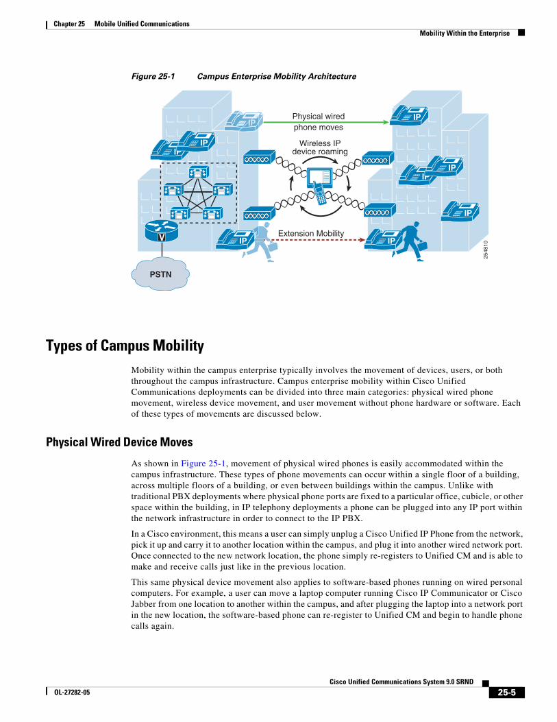
Figure 25-1 Campus Enterprise Mobility Architecture
Types of Campus MobilityMobility within the campus enterprise typically involves the movement of devices, users, or both throughout the campus infrastructure. Campus enterprise mobility within Cisco Unified Communications deployments can be divided into three main categories: physical wired phone movement, wireless device movement, and user movement without phone hardware or software. Each of these types of movements are discussed below.
Physical Wired Device Moves
As shown in Figure 25-1, movement of physical wired phones is easily accommodated within the campus infrastructure. These types of phone movements can occur within a single floor of a building, across multiple floors of a building, or even between buildings within the campus. Unlike with traditional PBX deployments where physical phone ports are fixed to a particular office, cubicle, or other space within the building, in IP telephony deployments a phone can be plugged into any IP port within the network infrastructure in order to connect to the IP PBX.
In a Cisco environment, this means a user can simply unplug a Cisco Unified IP Phone from the network, pick it up and carry it to another location within the campus, and plug it into another wired network port. Once connected to the new network location, the phone simply re-registers to Unified CM and is able to make and receive calls just like in the previous location.
This same physical device movement also applies to software-based phones running on wired personal computers. For example, a user can move a laptop computer running Cisco IP Communicator or Cisco Jabber from one location to another within the campus, and after plugging the laptop into a network port in the new location, the software-based phone can re-register to Unified CM and begin to handle phone calls again.
2548
10IP
IPIP
PSTN
V IP
IPIP
IPIPIP
Extension Mobility
Physical wiredphone moves
Wireless IPdevice roaming
IP
25-5Cisco Unified Communications System 9.0 SRND
OL-27282-05
Chapter 25 Mobile Unified CommunicationsMobility Within the Enterprise
To accommodate physical device mobility within the campus, care should be taken when physically moving phone devices or computers running software-based phones to ensure that the network connection used at a new location has the same type of IP connectivity, connection speed, quality of service, security, and network services such as in-line power and dynamic host control protocol (DHCP), as were provided by the previous location. Failure to replicate these connection parameters, services, and features will lead to reduced functionality or in some cases complete loss of functionality.
Wireless Device Roaming
Wireless devices can move or roam throughout the enterprise campus, as shown in Figure 25-1, provided a wireless LAN network has been deployed to provide wireless network connectivity to the campus edge.
Examples of wireless devices include Cisco Unified Wireless IP Phone 7925G, wirelessly attached Cisco Unified IP Phone 9971, Cisco Cius, and Cisco mobile clients such as Cisco Jabber (see Cisco Mobile Clients and Devices, page 25-60).
A WLAN network consists of one or more wireless access points (APs), which provide wireless network connectivity for wireless devices. Wireless APs are the demarcation point between the wireless network and the wired network. Multiple APs are deployed and distributed over a physical area of coverage in order to extend network coverage and capacity.
Because wireless devices and clients rely on the underlying WLAN infrastructure to carry both critical signaling and the real-time voice and video media traffic, it is necessary to deploy a WLAN network optimized for both data and real-time traffic. A poorly deployed WLAN network will be subjected to large amounts of interference and diminished capacity, leading not only to poor voice and video quality but in some cases dropped or missed calls. This will in turn render the WLAN deployment unusable for making and receiving voice calls. Therefore, when deploying wireless phones and clients, it is imperative to conduct a WLAN radio frequency (RF) site survey before, during, and after the deployment to determine appropriate cell boundaries, configuration and feature settings, capacity, and redundancy to ensure a successful voice and video over WLAN (VVoWLAN) deployment.
APs can be deployed autonomously within the network so that each AP is configured, managed, and operated independently from all other APs, or they can be deployed in a managed mode in which all APs are configured, managed, and controlled by a WLAN controller. In the latter mode, the WLAN controller
25-6Cisco Unified Communications System 9.0 SRND
OL-27282-05
Chapter 25 Mobile Unified CommunicationsMobility Within the Enterprise
is responsible for managing the APs as well as handling AP configuration and inter-AP roaming. In either case, to ensure successful VVoWLAN deployment, APs should be deployed using the following general guidelines:
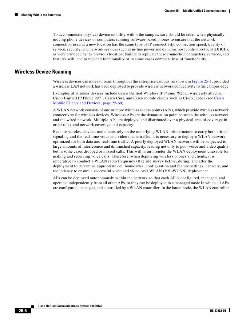
• As shown in Figure 25-2, non-adjacent WLAN AP channel cells should overlap by a minimum of 20%. This overlap ensures that a wireless device can successfully roam from one AP to the next as the device moves around within the campus location while still maintaining voice and data network connectivity. A device that successfully roams between two APs is able to maintain an active voice call without any noticeable change in the voice quality or path.
Figure 25-2 WLAN Channel Cell Overlap
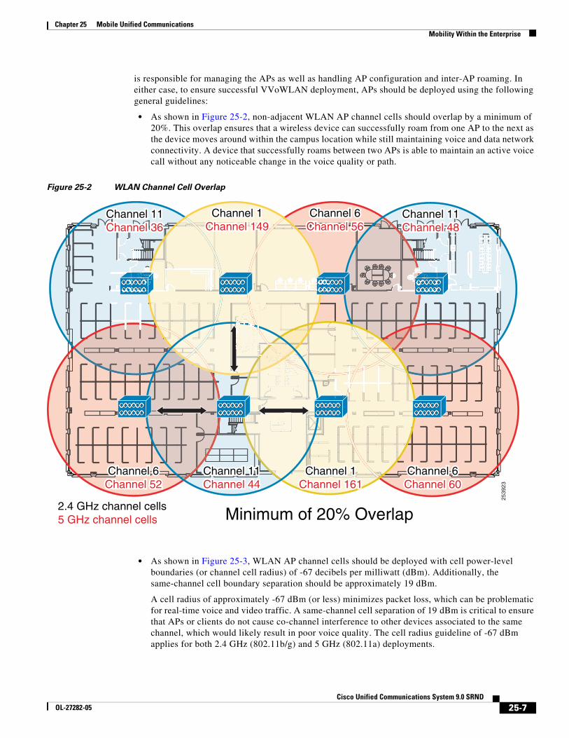
• As shown in Figure 25-3, WLAN AP channel cells should be deployed with cell power-level boundaries (or channel cell radius) of -67 decibels per milliwatt (dBm). Additionally, the same-channel cell boundary separation should be approximately 19 dBm.
A cell radius of approximately -67 dBm (or less) minimizes packet loss, which can be problematic for real-time voice and video traffic. A same-channel cell separation of 19 dBm is critical to ensure that APs or clients do not cause co-channel interference to other devices associated to the same channel, which would likely result in poor voice quality. The cell radius guideline of -67 dBm applies for both 2.4 GHz (802.11b/g) and 5 GHz (802.11a) deployments.
2539
23
Minimum of 20% Overlap2.4 GHz channel cells5 GHz channel cells
Channel 1Channel 1Channel 149Channel 149
Channel 6Channel 6Channel 56Channel 56
Channel 11Channel 11Channel 36Channel 36
Channel 11Channel 11Channel 48Channel 48
Channel 1Channel 1Channel 161Channel 161
Channel 6Channel 6Channel 60Channel 60
Channel 6Channel 6Channel 52Channel 52
Channel 11Channel 11Channel 44Channel 44
Channel 1Channel 149
Channel 6Channel 56
Channel 11Channel 36
Channel 11Channel 48
Channel 1Channel 161
Channel 6Channel 60
Channel 6Channel 52
Channel 11Channel 44
25-7Cisco Unified Communications System 9.0 SRND
OL-27282-05
Chapter 25 Mobile Unified CommunicationsMobility Within the Enterprise
Figure 25-3 WLAN Cell Radius and Same Channel Cell Separation
Note The 19 dBm same-channel cell separation is simplified and is considered ideal. It is very unlikely that this 19 dBm of separation can be achieved in most deployments. The most important RF design criteria are the -67 dBm cell radius and the minimum 20% recommended overlap between cells. Designing to these constraints optimizes channel separation.
Wireless roaming is not limited to wireless phones but also applies to software-based phones running on wireless personal computers. For example, a user can roam wirelessly throughout the campus with a laptop computer running Cisco IP Communicator or Cisco Jabber.
Most wireless APs, wireless phones, and wireless PC clients provide a variety of security options for providing secure access to the enterprise WLAN. In all cases, select a security method supported by both the WLAN infrastructure and the wireless devices that matches the security policies and requirements of the enterprise.
For more information on the Cisco Unified Wireless Network Infrastructure, see Wireless LAN Infrastructure, page 3-54. For more details on Voice over WLAN design, refer to the Voice over Wireless LAN Design Guide, available at
http://www.cisco.com/en/US/solutions/ns340/ns414/ns742/ns820/landing_voice_wireless.html
Extension Mobility (EM)
As shown in Figure 25-1, in addition to physical movement of wired and wireless phones, the users themselves can also move around within the campus infrastructure without phone or PC hardware. In these cases, a user can move their enterprise extension or number from one device to another by applying a device profile containing the user's enterprise number and other settings.
The EM feature allows users to log on to IP phones located throughout the campus using a set of security credentials (user ID and PIN number). Once logged on, the user's personal device profile, including their enterprise phone number, calling privileges, and even their configured speed dials, is applied to the phone temporarily until the user logs out of the device or the login times out. The EM feature is available as part of Unified CM.
The RADIUSof the cell
should be:–67 dBm
The separation ofsame channel cellsshould be:19 dBm
–67 dBm –86 dBm
2538
94
25-8Cisco Unified Communications System 9.0 SRND
OL-27282-05
Chapter 25 Mobile Unified CommunicationsMobility Within the Enterprise
This feature is particularly useful for mobile enterprise users who spend considerable amounts of time outside the enterprise and are physically in the office only occasionally. By providing temporary office space for these types of mobile users, sometimes referred to as hot seating or free seating, a system administrator can accommodate large numbers of mobile users who only occasionally and temporarily need to use IP phone hardware.
To leverage EM within the campus the Unified CM administrator must configure user device profile(s) and user credentials, and subscribe IP phone(s) to the EM phone service.
For more information about EM, see Extension Mobility, page 19-8.
Campus Enterprise Mobility High AvailabilityCampus enterprise mobility features and solutions should be configured and deployed in a redundant fashion to ensure high availability of mobility functions and features.
For example, to effectively support hard-wired IP phones and computers running software-based IP phones, redundant and prevalent network connections or ports should be made available. Furthermore, these redundant network connections should be deployed with appropriate characteristics, including appropriate security, quality of service, and other network-based features to ensure optimal operation and voice quality for wired devices as they are moved from location to location. Ultimately a successful campus mobility deployment is possible only if the underlying network connectivity, PSTN connectivity, and other applications and services are deployed in a highly available fashion.
Likewise, when deploying or tuning a WLAN network for wireless device connectivity and roaming, it is also important to consider high availability for wireless services. To ensure resilient and sufficient coverage for the number of devices being deployed, a WLAN network should be deployed in a manner that ensures that adequate and redundant cells of coverage are provided without overlapping same-channel cells. Network connectivity for wireless devices and clients can be made highly available by providing ample cell coverage without same-channel cell overlap and sufficient overlap of different channel cells in order to facilitate roaming between APs.
Finally, when leveraging EM for user mobility within the campus, you should deploy this feature in a redundant fashion so that the failure of a single node within the Unified CM cluster does not prevent the operation of the Extension Mobility feature. For information on deploying Cisco Extension Mobility in a highly available manner, see High Availability for Extension Mobility, page 19-16.
Capacity Planning for Campus Enterprise MobilityDeploying campus enterprise mobility successfully requires providing ample capacity to accommodate all mobile users exercising these mobility features and solutions.
Capacity considerations for physical movement of wired devices and computers depend completely on the number of network ports that are made available within the campus network infrastructure. In order for users to move devices around the campus, there must be some number of available network ports in each location that can be used to connect these mobile users' devices. A shortage of network ports to accommodate this wired device movement can result in an inability to move a device physically from one location to another.
When deploying wireless devices and leveraging wireless device roaming within the enterprise WLAN, it is also important to consider the device connectivity and call capacity of the WLAN infrastructure. Oversubscription of the campus WLAN infrastructure in terms of number of devices or number of active calls will result in dropped wireless connections, poor voice and video quality, and delayed or failed call setup. The chances of oversubscribing a deployment of voice and video over WLAN (VVoWLAN) are
25-9Cisco Unified Communications System 9.0 SRND
OL-27282-05
Chapter 25 Mobile Unified CommunicationsMobility Within the Enterprise
greatly minimized by deploying sufficient numbers of APs to handle required call capacities. AP call capacities are based on the number of simultaneous voice and/or video bidirectional streams that can be supported in a single channel cell area. The general rule for VVoWLAN call capacities is as follows:
• Maximum of 27 simultaneous voice over WLAN (VoWLAN) bidirectional streams per 802.11g/n (2.4 GHz) channel cell with Bluetooth disabled and 24 Mbps or higher data rates.
• Maximum of 27 simultaneous VoWLAN bidirectional streams per 802.11a/n (5 GHz) channel cell with 24 Mbps or higher data rates.
• Assuming a video resolution of 720p (high-definition) and a video bit rate of up to 1 Mbps, a maximum of 8 simultaneous VVoWLAN bidirectional streams per 802.11 g/n (2.4 GHz) with Bluetooth disabled or 802.11 a/n (5 GHz) channel cell.
These voice and video call capacity values are highly dependent upon the RF environment, the configured or supported video resolution and bit rates, the wireless endpoint and its specific capabilities, and the underlying WLAN system features. Actual capacities for a particular deployment could be less.
Note A single call between two wireless endpoints associated to the same AP is considered to be two simultaneous bidirectional streams.
Scalability of EM is dependent almost completely on the login/logout rate of the feature within Unified CM. It is important to know the number of extension mobility users enabled within the Unified CM cluster as well as how many users are moving around the campus and exercising this feature at any given time to ensure that sufficient EM login/logout capacity can be provided to these mobile users. For more information on EM capacity planning, see the chapter on Unified Communications Design and Deployment Sizing Considerations, page 29-1.
In all cases, the Unified CM cluster within the campus must have sufficient device registration capacity to handle device registration for moved devices, regardless of whether they are wired or wireless devices. Of course, assuming all devices being moved throughout the campus are already deployed within the campus network, then sufficient capacity within Unified CM should already be in place prior to the movement of devices. If new devices are added to the deployment for mobility purposes, however, device registration capacity should be considered and, if necessary, additional capacity should be added.
Finally, given the many features and functions provided by Unified CM, configuration and deployment of these mobility solutions does have sizing implications for the overall system. Determining actual system capacity is based on considerations such as number of endpoint devices, EM users, and busy hour call attempt (BHCA) rates to number of CTI applications deployed. For more information on general system sizing, capacity planning, and deployment considerations, see the chapter on Unified Communications Design and Deployment Sizing Considerations, page 29-1.
Design Considerations for Campus Enterprise MobilityObserve the following design recommendations when deploying campus enterprise mobility features and solutions:
• To accommodate physical device mobility within the campus ensure that the network connection used at a new location has the same type of IP connectivity (VLANs, inter-VLAN routing, and so forth), connection speed, quality of service, security, and network services (in-line power, dynamic host control protocol (DHCP), and so forth) as provided by the previous network connection. Failure to replicate these connection parameters, services, and features will lead to diminished functionality and in some case complete loss of functionality.
25-10Cisco Unified Communications System 9.0 SRND
OL-27282-05
Chapter 25 Mobile Unified CommunicationsMultisite Enterprise Mobility
• When deploying wireless IP devices and software-based clients, it is imperative to conduct a WLAN radio frequency (RF) site survey before, during, and after the deployment to determine appropriate cell boundaries, configuration and feature settings, capacity, and redundancy to ensure a successful voice over WLAN (VoWLAN) deployment.
• APs should be deployed with a minimum cell overlap of 20%. This overlap ensures that a dual-mode device can successfully roam from one AP to the next as the device moves around within a location, while still maintaining voice and data network connectivity.
• APs should be deployed with cell power level boundaries (or channel cell radius) of -67 dBm in order to minimize packet loss. Furthermore, the same-channel cell boundary separation should be approximately 19 dBm. A same-channel cell separation of 19 dBm is critical for ensuring that APs or clients do not cause co-channel interference to other devices associated to the same channel, which would likely result in poor voice and video quality.
• Deploy EM services in a highly redundant manner so that the loss of a single Unified CM node does not have adverse effects on the feature operation. If EM services are critical, consider deploying a server load balancing solution to route around Unified CM node failures and provide highly available functionality. For more information on EM high availability, see High Availability for Extension Mobility, page 19-16.
• Provide sufficient wireless voice and video call capacity on the campus network by deploying the appropriate number of wireless APs to handle the desired call capacity based on wireless user BHCA rates. Each 802.11g/n (2.4 GHz) or 802.11a/n (5 GHz) channel cell can support a maximum of 27 simultaneous voice-only calls with 24 Mbps or higher data rates. Each 802.11g/n (2.4 GHz) or 802.11a/n (5 GHz) channel cell can support a maximum of 8 simultaneous video calls assuming 720p video resolution at up to 1 Mbps bit rate. For 2.4 GHz WLAN deployments, Bluetooth must be disabled to achieve this capacity. Actual call capacity could be lower depending on RF environment, wireless endpoint type, and WLAN infrastructure.
Multisite Enterprise MobilityMultisite enterprise mobility refers to mobility within an enterprise with multiple physical locations, each with a unique IP address space and PSTN egress/ingress boundary. Mobility in this case includes not only the movement of users and endpoint devices within each physical location but also movement of users and endpoint devices between sites and locations.
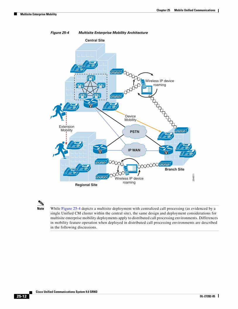
Multisite Enterprise Mobility ArchitectureAs shown in Figure 25-4, the multisite enterprise mobility architecture is based on two or more locations or sites geographically separated. Sites may vary in size from large numbers of users and devices in a central or campus site to smaller numbers of users and devices in medium-sized regional sites or smaller branch sites. Typically multisite enterprise deployments consist of IP WAN links interconnecting sites as well as local PSTN egress/ingress at each location. In addition, critical services are often replicated at each physical site in order to maintain features and functions during network outages between sites. From a mobility perspective, users and their devices may be mobile within a site or between sites.
25-11Cisco Unified Communications System 9.0 SRND
OL-27282-05
Chapter 25 Mobile Unified CommunicationsMultisite Enterprise Mobility
Figure 25-4 Multisite Enterprise Mobility Architecture
Note While Figure 25-4 depicts a multisite deployment with centralized call processing (as evidenced by a single Unified CM cluster within the central site), the same design and deployment considerations for multisite enterprise mobility deployments apply to distributed call processing environments. Differences in mobility feature operation when deployed in distributed call processing environments are described in the following discussions.
2548
11
IPIP
V
IPIP
IP
IP
V IP
IPIP WAN
IP
ExtensionMobility
IP
DeviceMobility
PSTN
Branch Site
Regional Site
Central Site
Wireless IP deviceroaming
Wireless IP deviceroaming
V
25-12Cisco Unified Communications System 9.0 SRND
OL-27282-05
Chapter 25 Mobile Unified CommunicationsMultisite Enterprise Mobility
Types of Multisite Enterprise MobilityMobility within a multisite enterprise deployment involves not only the movement of devices, users, or both within a single site, but also movement of users and devices between sites.
The same types of mobility features and solutions supported with campus or single site enterprise deployments apply to intra-site movement of users and devices within any single site of a multisite deployment. These include physical wired phone movement, wireless phone roaming, and extension mobility. For information on these types of mobility solutions and functions, see Campus Enterprise Mobility, page 25-4.
For inter-site mobility in a multisite deployment, these same mobility features are also supported in much the same way. However, the key difference with these features when applied between two or more sites is that they are augmented with the Device Mobility feature. The Device Mobility feature provides a mechanism for dynamic location awareness of devices based on the IP address the device uses when connecting to the enterprise network.
Physical Wired Device Moves
Movement of physical wired phones is easily accommodated within each site of a multisite deployment as well as between sites. Just as with a campus or single-site deployment, wired device movement limited to a single site of a multisite deployment simply involves unplugging a Cisco Unified IP Phone from the network, moving it to another location within the site, and plugging it into another wired network port. Once connected to the new network location, the phone simply re-registers to Unified CM and is able to make and receive calls just like in the previous location.
Movement of wired devices between sites or locations in a multisite deployment involve the same basic behavior. However, the Device Mobility feature, when combined with this type of mobility, ensures that call admission control operations and gateway and codec selection are appropriate once the device re-registers in the new location to which it has been moved. See Device Mobility, page 25-14, for information about this feature.
Wireless Device Roaming
Just as with a single-site campus deployment, wireless devices can move or roam throughout a multisite enterprise deployment, as shown in Figure 25-4, provided wireless LAN network infrastructure is available at each site to provide wireless network connectivity. However, as with the movement of wired phones between sites, the Device Mobility feature should also be deployed for wireless devices to ensure that the correct gateway and codec are used when making and receiving calls and that call admission control manages bandwidth appropriately. See Device Mobility, page 25-14, for information about this feature.
For distributed call processing environments, just as with wired phones, wireless devices should be configured to register with only a single Unified CM cluster to avoid potential issues with call routing.
25-13Cisco Unified Communications System 9.0 SRND
OL-27282-05
Chapter 25 Mobile Unified CommunicationsMultisite Enterprise Mobility
Extension Mobility (EM)
In addition to supporting EM within a single site, as illustrated in Figure 25-4, this feature is also supported between sites to enable users to move between sites within the enterprise and log on to phones in each locations.
EM is also supported in distributed call processing deployments when users move between sites and phones on different Unified CM clusters. To support extension mobility in distributed call processing environments, you might need to configure the Cisco Extension Mobility Cross Cluster (EMCC) feature. For information about this feature, see Extension Mobility Cross Cluster (EMCC), page 19-10.
Device Mobility
In Cisco Unified Communications Manager (Unified CM), a site or a physical location is identified using various settings such as locations, regions, calling search spaces, and media resources. Cisco Unified IP Phones residing in a particular site are statically configured with these settings. Unified CM uses these settings for proper call establishment, call routing, media resource selection, and so forth. However, when dual-mode phones and other mobile client devices such as Cisco Cius or Cisco Unified Wireless IP Phones are moved from their home site to a remote site, they retain the home settings that are statically configured on the phones. Unified CM then uses these home settings on the phones in the remote site. This situation is undesirable because it can cause problems with call routing, codec selection, media resource selection, and other call processing functions.
Cisco Unified CM uses a feature called Device Mobility, which enables Unified CM to determine if the IP phone is at its home location or at a roaming location. Unified CM uses the device's IP subnets to determine the exact location of the IP phone. By enabling device mobility within a cluster, mobile users can roam from one site to another, thus acquiring the site-specific settings. Unified CM then uses these dynamically allocated settings for call routing, codec selection, media resource selection, and so forth.
This section begins with a discussion surrounding the main purpose for the Device Mobility feature, followed by an in-depth discussion of the Device Mobility feature itself. This discussion covers the various components and configuration constructs of the Device Mobility feature. This section also presents an in-depth discussion of the impact of the Device Mobility feature on the enterprise dial plan, including the implication for various dial plan models.
25-14Cisco Unified Communications System 9.0 SRND
OL-27282-05
Chapter 25 Mobile Unified CommunicationsMultisite Enterprise Mobility
Need for Device Mobility
This section explains the need for device mobility when there are many mobile users in a Unified CM cluster.
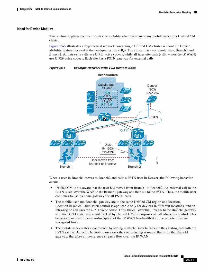
Figure 25-5 illustrates a hypothetical network containing a Unified CM cluster without the Device Mobility feature, located at the headquarter site (HQ). The cluster has two remote sites, Branch1 and Branch2. All intra-site calls use G.711 voice codecs, while all inter-site calls (calls across the IP WAN) use G.729 voice codecs. Each site has a PSTN gateway for external calls.
Figure 25-5 Example Network with Two Remote Sites
When a user in Branch1 moves to Branch2 and calls a PSTN user in Denver, the following behavior occurs:
• Unified CM is not aware that the user has moved from Branch1 to Branch2. An external call to the PSTN is sent over the WAN to the Branch1 gateway and then out to the PSTN. Thus, the mobile user continues to use its home gateway for all PSTN calls.
• The mobile user and Branch1 gateway are in the same Unified CM region and location. Location-based call admission control is applicable only for devices in different locations, and an intra-region call uses the G.711 voice codec. Thus, the call over the IP WAN to the Branch1 gateway uses the G.711 codec and is not tracked by Unified CM for purposes of call admission control. This behavior can result in over-subscription of the IP WAN bandwidth if all the remote links are low-speed links.
• The mobile user creates a conference by adding multiple Branch2 users to the existing call with the PSTN user in Denver. The mobile user uses the conferencing resource that is on the Branch1 gateway, therefore all conference streams flow over the IP WAN.
1901
77
Denver(303)
555-1234
PSTN
IP
M
M
M M
M
IP
CallManagerCluster
IP IP IP
Branch 1
Headquarters
V
IP
IP IP IP
Branch 2
G.711
User moves fromBranch1 to Branch2
Dials9-1-303-555-1234
25-15Cisco Unified Communications System 9.0 SRND
OL-27282-05
Chapter 25 Mobile Unified CommunicationsMultisite Enterprise Mobility
Note Device Mobility is an intra-cluster feature and does not span multiple Unified CM clusters. In distributed call processing environments, Device Mobility must be enabled and configured on each Unified CM cluster within the deployment.
Device Mobility Architecture
The Unified CM Device Mobility feature helps solve the problems mentioned above. This section briefly explains how the feature works. However, for a detailed explanation of this feature, refer to the product documentation available on http://www.cisco.com.
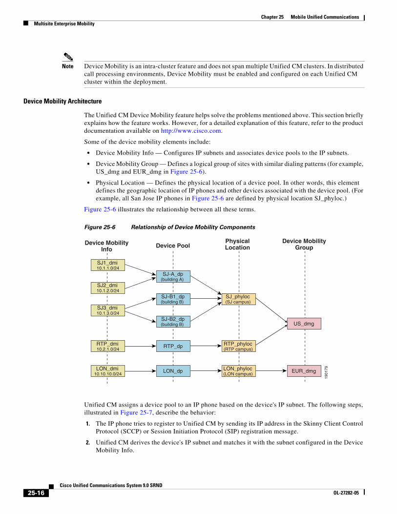
Some of the device mobility elements include:
• Device Mobility Info — Configures IP subnets and associates device pools to the IP subnets.
• Device Mobility Group — Defines a logical group of sites with similar dialing patterns (for example, US_dmg and EUR_dmg in Figure 25-6).
• Physical Location — Defines the physical location of a device pool. In other words, this element defines the geographic location of IP phones and other devices associated with the device pool. (For example, all San Jose IP phones in Figure 25-6 are defined by physical location SJ_phyloc.)
Figure 25-6 illustrates the relationship between all these terms.
Figure 25-6 Relationship of Device Mobility Components
Unified CM assigns a device pool to an IP phone based on the device's IP subnet. The following steps, illustrated in Figure 25-7, describe the behavior:
1. The IP phone tries to register to Unified CM by sending its IP address in the Skinny Client Control Protocol (SCCP) or Session Initiation Protocol (SIP) registration message.
2. Unified CM derives the device's IP subnet and matches it with the subnet configured in the Device Mobility Info.
1901
79
SJ1_dmi10.1.1.0/24
SJ2_dmi10.1.2.0/24
RTP_dmi10.2.1.0/24
SJ-A_dp(building A)
SJ-B1_dp(building B)
SJ3_dmi10.1.3.0/24
SJ-B2_dp(building B)
RTP_dp
LON_dmi10.10.10.0/24
LON_dp
SJ_phyloc(SJ campus)
RTP_phyloc(RTP campus)
LON_phyloc(LON campus)
US_dmg
EUR_dmg
Device MobilityInfo
Device PoolPhysicalLocation
Device MobilityGroup
25-16Cisco Unified Communications System 9.0 SRND
OL-27282-05
Chapter 25 Mobile Unified CommunicationsMultisite Enterprise Mobility
3. If the subnet matches, Unified CM provides the device with a new configuration based on the device pool configuration.
Figure 25-7 Phone Registration Process
Unified CM uses a set of parameters under the device pool configuration to accommodate Device Mobility. These parameters are of the following two main types:
• Roaming Sensitive Settings, page 25-17
• Device Mobility Related Settings, page 25-18
Roaming Sensitive Settings
The parameters under these settings will override the device-level settings when the device is roaming within or outside a Device Mobility Group. The parameters included in these settings are:
• Date/time Group
• Region
• Media Resource Group List
• Location
• Network Locale
• SRST Reference
• Physical Location
• Device Mobility Group
The roaming sensitive settings primarily help in achieving proper call admission control and voice codec selection because the location and region configurations are used based on the device's roaming device pool.
For more details on various call admission control techniques, see the chapter on Call Admission Control, page 11-1.
The roaming sensitive settings also update the media resource group list (MRGL) so that appropriate remote media resources are used for music on hold, conferencing, transcoding, and so forth, thus utilizing the network efficiently.
The roaming sensitive settings also update the Survivable Remote Site Telephony (SRST) gateway. Mobile users register to a different SRST gateway while roaming. This registration can affect the dialing behavior when the roaming phones are in SRST mode.
25-17Cisco Unified Communications System 9.0 SRND
OL-27282-05
Chapter 25 Mobile Unified CommunicationsMultisite Enterprise Mobility
For example, if a user moves with their phone to a new location that loses connectivity to Unified CM, then based on the roaming sensitive Device Mobility settings, a new SRST reference is configured for the moved phone and the moved phone will now be under control of the local roaming location SRST router. When this occurs, not only would the user's phone be unreachable from the PSTN or other sites because the device’s DID will not have changed and will still be anchored at their home location, but in addition reachabililty from devices within the local failed site might be difficult without the use of abbreviated dialing as implemented within SRST.
As an example, assume that a user moves a phone from their home location in San Jose, which has a directory number of 51234 and an associated DID of 408 555 1234 to a remote location in New York, and that the link between the New York site and San Jose fails shortly after the user roams to the New York location. In this scenario the phones in the New York site will all fail-over to the SRST router in that site. The roaming/moved phone will also register to the New York SRST router because its SRST reference was updated based on the device mobility roaming sensitive settings. In this scenario, the local New York devices will register to the SRST router with five-digit extensions just as they do to Unified CM, and as a result the roaming phone still has a directory number of 51234. To reach the roaming phone from all other sites and from the PSTN, the number 408 555 1234 will be routed to the San Jose PSTN gateway to which this particular DID is anchored. Because the New York site is disconnected from the San Jose site, any such calls will be routed to the users’ voicemail boxes since they will be unreachable at their desk phones. Likewise, calls internally within the local failed site will have to be dialed using five-digit abbreviated dialing or based on the configured digit prefixing as defined by the dialplan-pattern and extension-length commands within the SRST router. In either case, local callers will have to be understand the required dialing behavior for reaching the local roaming device by abbreviated dialing. In some cases this may be simply five-digit dialing or it may be that users have to dial a special digit prefix to reach the local roaming phone. The same logic applies to outbound dialing from the moved or roaming phone in New York because its dialing behavior might have to be altered in order to reach local extensions using abbreviated dialing. Outbound dialing to the PSTN from the local roaming device should remain the same, however.
Device Mobility Related Settings
The parameters under these settings will override the device-level settings only when the device is roaming within a Device Mobility Group. The parameters included in these settings are:
• Device Mobility Calling Search Space
• AAR Calling Search Space
• AAR Group
• Calling Party Transformation CSS
The device mobility related settings affect the dial plan because the calling search space dictates the patterns that can be dialed or the devices that can be reached.
25-18Cisco Unified Communications System 9.0 SRND
OL-27282-05
Chapter 25 Mobile Unified CommunicationsMultisite Enterprise Mobility
Device Mobility Group
Device Mobility Group, as explained earlier, defines a logical group of sites with similar dialing patterns (for example, sites having the same PSTN access codes and so forth). With this guideline, all sites have similar dialing patterns in the site-specific calling search spaces. Sites having different dialing behavior are in a different Device Mobility Group. As illustrated in Figure 25-6, the San Jose and RTP sites’ Device Mobility Info, Device Pools, and Physical Locations are different; however, all of these have been assigned to the same Device Mobility Group US_dmg because the required dialing patterns and PSTN access codes are the same between the two locations. On the other hand, the London site is assigned to a separate Device Mobility Group EUR_dmg due to the fact that the required dialing patterns and PSTN access codes there are different than those of the US sites. A user roaming within a Device Mobility Group may preserve his dialing behavior at the remote location even after receiving a new calling search space. A user roaming outside the Device Mobility Group may still preserve his dialing behavior at the remote location because he uses his home calling search space.
However, if a Device Mobility Group is defined with sites having different dialing patterns (for example, one site requires users to dial 9 to get an outside line while another site requires users to dial 8 to get an outside line), then a user roaming within that Device Mobility Group might not preserve his same dialing behavior at all locations. A user might have to dial digits differently at different locations after receiving a new calling search space at each location. This behavior can be confusing for users, therefore Cisco recommends against assigning sites with different dialing patterns to the same Device Mobility Group.
25-19Cisco Unified Communications System 9.0 SRND
OL-27282-05
Chapter 25 Mobile Unified CommunicationsMultisite Enterprise Mobility
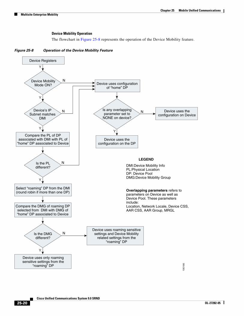
Device Mobility Operation
The flowchart in Figure 25-8 represents the operation of the Device Mobility feature.
Figure 25-8 Operation of the Device Mobility Feature
1901
66
Y
Y
Y
Y
Y
Y
N
N N
Device MobilityMode ON?
Is the PLdifferent?
Is the DMGdifferent?
Device uses configurationof “home” DP
Device uses theconfiguration on the DP
Overlapping parameters refers toparameters on Device as well asDevice Pool. These parametersinclude:Location, Network Locale, Device CSS,AAR CSS, AAR Group, MRGL
Is any overlappingparameter set to
NONE on device?
LEGEND
DMI:Device Mobility InfoPL:Physical LocationDP: Device PoolDMG:Device Mobility Group
Device Registers
Device’s IPSubnet matches
DMI
Compare the PL of DPassociated with DMI with PL of
“home” DP associated to Device
Select “roaming” DP from the DMI(round robin if more than one DP)
Compare the DMG of roaming DPselected from DMI with DMG of“home” DP associated to Device
Device uses only roamingsensitive settings from the
“roaming” DP
NDevice uses roaming sensitivesettings and Device Mobility
related settings from the“roaming” DP
N
Device uses theconfiguration on Device
25-20Cisco Unified Communications System 9.0 SRND
OL-27282-05
Chapter 25 Mobile Unified CommunicationsMultisite Enterprise Mobility
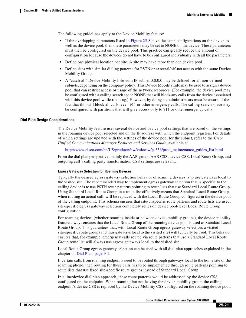
The following guidelines apply to the Device Mobility feature:
• If the overlapping parameters listed in Figure 25-8 have the same configurations on the device as well as the device pool, then these parameters may be set to NONE on the device. These parameters must then be configured on the device pool. This practice can greatly reduce the amount of configuration because the devices do not have to be configured individually with all the parameters.
• Define one physical location per site. A site may have more than one device pool.
• Define sites with similar dialing patterns for PSTN or external/off-net access with the same Device Mobility Group.
• A "catch-all" Device Mobility Info with IP subnet 0.0.0.0 may be defined for all non-defined subnets, depending on the company policy. This Device Mobility Info may be used to assign a device pool that can restrict access or usage of the network resources. (For example, the device pool may be configured with a calling search space NONE that will block any calls from the device associated with this device pool while roaming.) However, by doing so, administrators must be aware of the fact that this will block all calls, even 911 or other emergency calls. The calling search space may be configured with partitions that will give access only to 911 or other emergency calls.
Dial Plan Design Considerations
The Device Mobility feature uses several device and device pool settings that are based on the settings in the roaming device pool selected and on the IP address with which the endpoint registers. For details of which settings are updated with the settings of the device pool for the subnet, refer to the Cisco Unified Communications Manager Features and Services Guide, available at
http://www.cisco.com/en/US/products/sw/voicesw/ps556/prod_maintenance_guides_list.html
From the dial plan perspective, mainly the AAR group, AAR CSS, device CSS, Local Route Group, and outgoing call’s calling party transformation CSS settings are relevant.
Egress Gateway Selection for Roaming Devices
Typically the desired egress gateway selection behavior of roaming devices is to use gateways local to the visited site. The recommended way to implement egress gateway selection that is specific to the calling device is to use PSTN route patterns pointing to route lists that use Standard Local Route Group. Using Standard Local Route Group in a route list effectively means that Standard Local Route Group, when routing an actual call, will be replaced with the Local Route Group configured in the device pool of the calling endpoint. This schema ensures that site-unspecific route patterns and route lists are used; site-specific egress gateway selection completely relies on device pool-level Local Route Group configuration.
For roaming devices (whether roaming inside or between device mobility groups), the device mobility feature always ensures that the Local Route Group of the roaming device pool is used as Standard Local Route Group. This guarantees that, with Local Route Group egress gateway selection, a visited site-specific route group (and thus gateways local to the visited site) will typically be used. This behavior ensures that, for example, emergency calls routed via route patterns that use a Standard Local Route Group route list will always use egress gateways local to the visited site.
Local Route Group egress gateway selection can be used with all dial plan approaches explained in the chapter on Dial Plan, page 9-1.
If certain calls from roaming endpoints need to be routed through gateways local to the home site of the roaming phone, then routing for these calls has to be implemented through route patterns pointing to route lists that use fixed site-specific route groups instead of Standard Local Group.
In a line/device dial plan approach, these route patterns would be addressed by the device CSS configured on the endpoint. When roaming but not leaving the device mobility group, the calling endpoint’s device CSS is replaced by the Device Mobility CSS configured on the roaming device pool.
25-21Cisco Unified Communications System 9.0 SRND
OL-27282-05
Chapter 25 Mobile Unified CommunicationsMultisite Enterprise Mobility
If fixed egress gateway selection is required for some calls and the route patterns for those calls are addressed by the device CSS, you have to make sure that roaming devices always roam across device mobility groups. This will guarantee that roaming endpoints always use the device CSS configure on the endpoint.
When using the +E.164 dial plan approach explained in the chapter on Dial Plan, page 9-1, all PSTN route patterns are accessible by the line CSS, which is not changed or updated for roaming devices. In this dial plan, site-specific route patterns tying specific PSTN destinations to fixed gateways (for example, in the home location of the roaming device) are not affected by device mobility operation.
25-22Cisco Unified Communications System 9.0 SRND
OL-27282-05
Chapter 25 Mobile Unified CommunicationsMultisite Enterprise Mobility
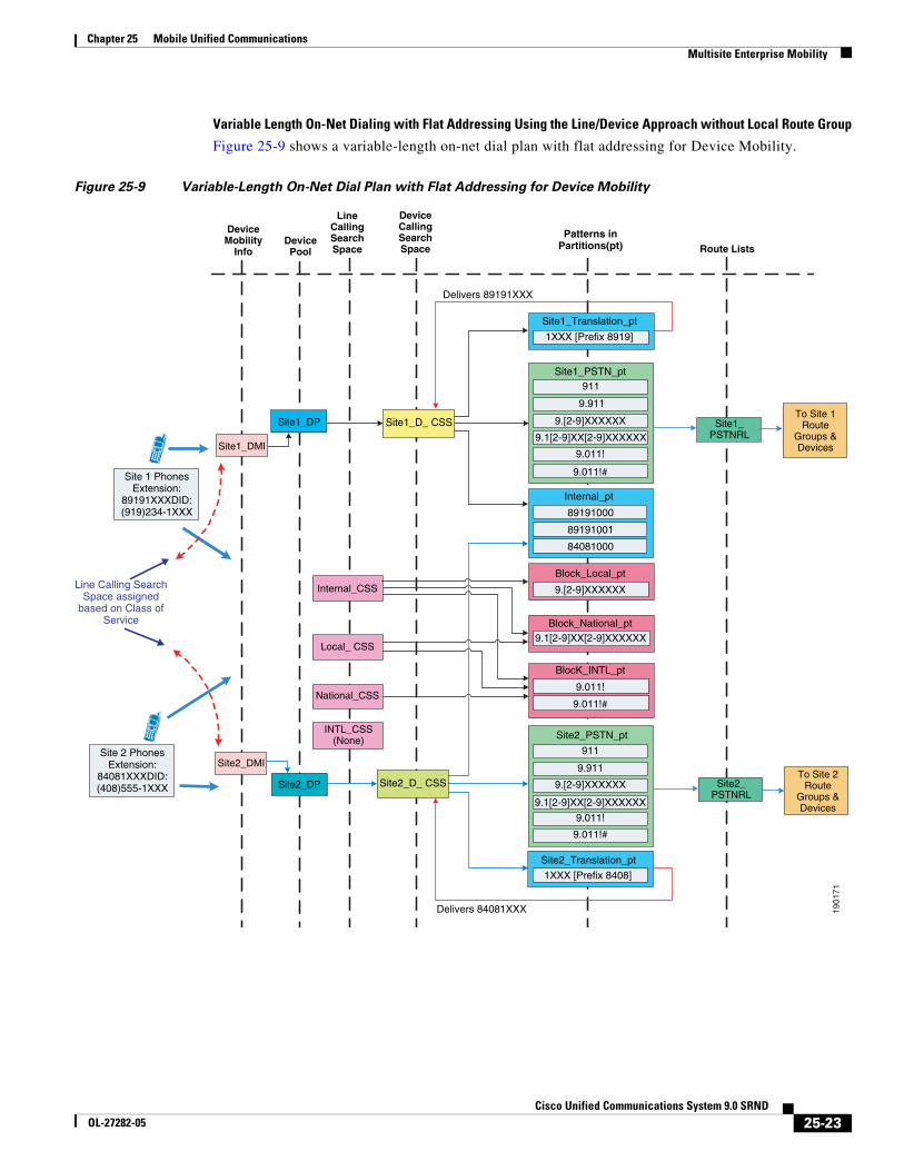
Variable Length On-Net Dialing with Flat Addressing Using the Line/Device Approach without Local Route Group
Figure 25-9 shows a variable-length on-net dial plan with flat addressing for Device Mobility.
Figure 25-9 Variable-Length On-Net Dial Plan with Flat Addressing for Device Mobility
1901
71
911
9.911
Line Calling SearchSpace assigned
based on Class ofService
Site1_DMI
Site1_DP
Site2_DMI
Site2_DP Site2_PSTNRL
To Site 2Route
Groups &Devices
To Site 1Route
Groups &Devices
Site1_PSTNRL
DeviceMobility
InfoDevicePool
LineCallingSearchSpace
DeviceCallingSearchSpace
Patterns inPartitions(pt) Route Lists
INTL_CSS(None)
National_CSS
Local_ CSS
Internal_CSS
Site1_D_ CSS
Site2_D_ CSS
Site1_PSTN_pt
9.[2-9]XXXXXX
9.1[2-9]XX[2-9]XXXXXX
9.011!
9.011!#
Block_Local_pt
9.[2-9]XXXXXX
Block_National_pt9.1[2-9]XX[2-9]XXXXXX
BlocK_INTL_pt
9.011!
9.011!#
9.911
9.[2-9]XXXXXX
9.1[2-9]XX[2-9]XXXXXX
9.011!
9.011!#
Site2_PSTN_pt
911
Delivers 89191XXX
Internal_pt
Delivers 84081XXX
Site 1 PhonesExtension:
89191XXXDID:(919)234-1XXX
Site 2 PhonesExtension:
84081XXXDID:(408)555-1XXX
Site1_Translation_pt
1XXX [Prefix 8919]
89191000
89191001
84081000
Site2_Translation_pt
1XXX [Prefix 8408]
25-23Cisco Unified Communications System 9.0 SRND
OL-27282-05
Chapter 25 Mobile Unified CommunicationsMultisite Enterprise Mobility
The following design considerations apply to the dial plan model in Figure 25-9:
• In this dial plan the translation patterns implementing 4-digit intra-site dialing are addressed by the device CSS. This is done to avoid the requirement to have site-specific line CSSs. Mobile users inherit the intra-site dialing of the visited site because the device CSS is updated with the roaming device pool’s device mobility CSS (assuming the user is roaming inside the device mobility group). If this behavior is not desired, consider defining each site as a Device Mobility Group. However, users must be aware that, for any external PSTN calls, the mobile phone continues to use the home gateway and therefore consumes WAN bandwidth. This can be avoided by using Standard Local Route Group (see Egress Gateway Selection for Roaming Devices, page 25-21).
• Additional device calling search spaces may be configured for roaming users with access only to the PSTN and internal phones partitions. This configuration will need at least one additional device pool and calling search space per site. Thus, N sites will need N device pools and N calling search spaces. However, this configuration will not require defining each site as a Device Mobility Group. With this configuration mobile users, when roaming, will not have access to dialing habits through translation patterns in their device CSS.
• Mobile users registered with a remote SRST gateway have unique extensions. However, mobile users must be aware that no PSTN user can call them when they are registered to a remote SRST gateway.
+E.164 Dial Plan with Traditional Approach and Local Route Group
As described in the chapter on Dial Plan, page 9-1, the line/device approach has some specific issues, and creating a +E-164 dial plan based on the line/device approach is not recommended. The recommended approach for +E.164 dial plans is to combine class of service selection and dialing normalization on the line CSS and use the Local Route Group feature to address the requirement for site-specific egress gateway selection. In this approach the device CSS on the phone is not used at all. If you combine this approach with device mobility, the only roaming sensitive component of the design is the device pools’ local route group. For a roaming phone (whether roaming inside or between device mobility groups), the local route group defined on the phone’s home device pool will always be updated with the local route group defined on the roaming device pool. This guarantees that all calls always egress through a gateway local to the visited site.
Multisite Enterprise Mobility High AvailabilityMultisite enterprise mobility features and solutions should be configured and deployed in a redundant fashion in order to ensure high availability of mobility functionality. High availability considerations for wired phone moves, wireless roaming, and EM in multisite mobility deployments are similar to those for campus mobility deployments. Just as with campus environments, redundant network ports, wireless cell coverage, and Unified CM nodes handling extension mobility logins and logouts should be provided to ensure highly available services.
Similarly, it is important to consider high availability of the Device Mobility feature. Because Device Mobility is natively integrated within Unified CM, the failure of a cluster node should have no impact on the functionality of Device Mobility. Device pool, Device Mobility Info, Device Mobility Group, and all other configurations surrounding Device Mobility are preserved if there is a failure of the publisher node or a call processing (subscriber) node. Additionally, if there is a call processing node failure, affected phones will fail-over to their secondary call processing node or Survivable Remote Site Telephony (SRST) reference router as usual based on the Unified CM Group construct.
25-24Cisco Unified Communications System 9.0 SRND
OL-27282-05
Chapter 25 Mobile Unified CommunicationsMultisite Enterprise Mobility
Capacity Planning for Multisite Enterprise MobilityAs for Device Mobility scalability considerations, there are no specific or enforced capacity limits surrounding this feature and the various configuration constructs (device pools, device mobility groups, and so forth). For more information on general system sizing, capacity planning, and deployment considerations, see the chapter on Unified Communications Design and Deployment Sizing Considerations, page 29-1
Design Considerations for Multisite Enterprise MobilityAll campus enterprise mobility design considerations apply to multisite enterprise mobility deployments as well (seeDesign Considerations for Campus Enterprise Mobility, page 25-10). The following additional design recommendations apply specifically to multisite mobility environments:
• Ensure that all critical services (device registration, PSTN connectivity, DNS, DHCP, and so forth) are deployed at each site in a multisite deployment so that failure of the connection between the site and other sites does not disrupt critical operations. In addition, ensure that a sufficient number of physical network ports and wireless LAN APs are available at each site to support movement of devices and required call capacity.
• In situations in which sites with different dialing patterns (for example, sites having different PSTN access codes) are configured in the same Device Mobility Group, roaming users might have to dial numbers differently based on their location, which can be confusing. For this reason, Cisco recommends assigning sites with similar dialing patterns (for example, sites having the same PSTN access codes) to the same Device Mobility Group. Doing so ensures that roaming users can dial numbers the same way at all sites within the Device Mobility Group.
• The Device Mobility settings from the "roaming" device pool are applied only when users roam within the same Device Mobility Group; therefore, avoid roaming between different Device Mobility Groups because the resulting call routing behavior will cause originated calls from the moved phone to be routed using the "home" or device-configured calling search space. This can lead to unnecessary consumption of WAN bandwidth because the call might be routed through a different site's gateway rather than the local "roaming" gateway.
• Define only one physical location per site. This ensures that device mobility is engaged only in scenarios in which a user is roaming between sites. For roaming within the same site, the concerns that mandate Device Mobility (for example, WAN bandwidth consumption, codec selection, and call admission control) are not present because low-speed links typically are not deployed within a single site.
• In failover scenarios, "roaming" phones will utilize the SRST reference/gateway as dictated by the "roaming" device pool's roaming sensitive settings. Therefore, in these situations the "roaming" phone is unreachable from the PSTN due to the fact that the DID for this phone is anchored in another location's PSTN gateway. Furthermore, for outbound calls from the "roaming" phone, dialing behavior might have to be altered for things such as PSTN access codes, and speed dials configured on the phone might not be usable.
• If your system requires the ability to use abbreviated dialing or to use speed dials that rely on abbreviated dialing, Cisco recommends using a Uniform On-net dial plan model because it will ensure that abbreviated dialing (direct or through speed dials) continues to work even when the mobile user's phone is in a roaming location. Abbreviated dialing is still possible with this dial plan model because all extensions or directory numbers are unique across all sites, and therefore abbreviated dialing can be used universally due to the fact that there are no overlapping extensions.
25-25Cisco Unified Communications System 9.0 SRND
OL-27282-05
Chapter 25 Mobile Unified CommunicationsRemote Enterprise Mobility
• If your system uses a Variable Length On-net dial plan model (using either the line/device or the line-CSS-only +E.164 dial plan approach), Cisco recommends configuring speed dials in a universal way so that a single unique extension can be reached when called. By configuring speed dials using full +E.164 numbers or using site or access codes, you can enable roaming users to use the same speed dials at any location.
• If Device Mobility is enabled for users who on occasion access the enterprise network through a VPN connection, Device Mobility Info (DMI) for VPN attached phones should contain IP subnets distributed or owned by the VPN concentrators to ensure that "roaming" to a VPN location results in appropriate dynamic Device Mobility configuration changes. Be sure to associate the DMI with the same device pool that is used for any devices co-located with the VPN concentrators.
Remote Enterprise MobilityRemote enterprise mobility refers to mobile users in locations remote from the enterprise but still attached to the enterprise network infrastructure through secure connections over the public Internet. Mobility here deals with the placement of endpoint devices in these remote locations and the movement of users, and in some cases their mobile devices, between the enterprise and these locations either frequently or on occasion.
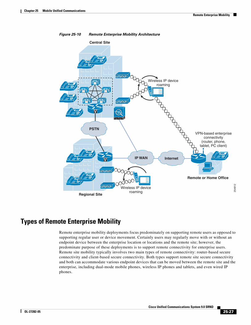
Remote Enterprise Mobility ArchitectureAs illustrated in Figure 25-10, the remote enterprise mobility architecture is based on a remote physical location, typically an employee home office but also any remote location capable of secure connection back to the enterprise over the Internet. These remote sites typically consist of an IP network with connections for a user's computer, telephone, and other equipment or endpoints. In some cases this IP network may be behind an enterprise controlled and configured VPN router that provides a secure tunnel between the remote location and the enterprise network. In other cases, the remote site IP network is connected to the Internet through a user-provided router, and user computer or endpoint devices must use software-based VPN client capabilities to create secure connections back to the enterprise network. Wireless connectivity may also be provided in the remote location to allow wireless attachment of the user's computer or endpoint. When wireless connectivity is provided at the remote location, wireless phones may be moved from the enterprise network to the home office, allowing users to leverage wireless enterprise devices or mobile phones within the remote location to make and receive calls.
25-26Cisco Unified Communications System 9.0 SRND
OL-27282-05
Chapter 25 Mobile Unified CommunicationsRemote Enterprise Mobility
Figure 25-10 Remote Enterprise Mobility Architecture
Types of Remote Enterprise MobilityRemote enterprise mobility deployments focus predominately on supporting remote users as opposed to supporting regular user or device movement. Certainly users may regularly move with or without an endpoint device between the enterprise location or locations and the remote site; however, the predominate purpose of these deployments is to support remote connectivity for enterprise users. Remote site mobility typically involves two main types of remote connectivity: router-based secure connectivity and client-based secure connectivity. Both types support remote site secure connectivity and both can accommodate various endpoint devices that can be moved between the remote site and the enterprise, including dual-mode mobile phones, wireless IP phones and tablets, and even wired IP phones.
2548
12
IPIP
IPIP
IP WAN
IP
Remote or Home Office
Regional Site
Central Site
Wireless IP deviceroaming
Wireless IP deviceroaming
IPInternetIPIP
PSTN
V
V
VPN-based enterpriseconnectivity
(router, phone,tablet, PC client)
IP
IP
25-27Cisco Unified Communications System 9.0 SRND
OL-27282-05
Chapter 25 Mobile Unified CommunicationsRemote Enterprise Mobility
Client-Based Secure Remote Connectivity
Wireless and wired IP phones and software-based PC telephony clients can be connected to remote site locations, as shown in Figure 25-10. These devices and endpoints are responsible for creating secure VPN connections back to the enterprise VPN head-end termination concentrator.
Examples of these types of devices include wirelessly attached mobile client devices using VPN client or application capabilities such as the Cisco Jabber for iPhone and Android clients (see Cisco Mobile Clients and Devices, page 25-60), wired Cisco Unified IP Phones such as the Cisco Unified IP Phone 7965 that uses a built-in VPN client, and personal computers running software-based telephony clients such as Cisco Jabber that uses a software-based VPN client for connectivity to the enterprise network.
Router-Based Secure Remote Connectivity
On the other hand, remote site connectivity can be handled through router-based secure VPN tunnels. In these types of scenarios the deployed remote site router, which may be able to provide wireless network connectivity as well, is responsible for setting up and securing a VPN tunnel back to the enterprise network. This in effect extends the enterprise network boundary to the remote site location. The advantage of this type of connectivity is that a wider range of devices and endpoints may be deployed in the remote site because these devices are not responsible for providing secure connectivity and therefore do not require special software or configuration. Instead, these devices simply connect to the remote site network and leverage the secure VPN IP path from the remote site router to the enterprise VPN head-end.
An example of this type of route-based remote site connectivity is the Cisco Virtual Office solution.
Device Mobility and VPN-Based Remote Enterprise Connectivity
Whether you are deploying client-based or router-based secure remote connectivity, the Device Mobility feature may be used to ensure that call admission control and codec are correctly negotiated for endpoint devices and that the appropriate enterprise site PSTN gateway and media resources are utilized. Based on the IP address of the endpoint device as received over the VPN connection, Unified CM will dynamically determine the location of the device.
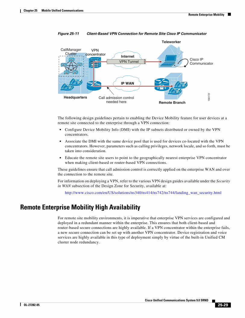
Figure 25-11 shows an example of client-based secure remote connectivity where a Cisco IP Communicator software phone is running on a remote site computer. This software-based IP phone is connected through a client-based VPN back to the enterprise and registered to Unified CM.
25-28Cisco Unified Communications System 9.0 SRND
OL-27282-05
Chapter 25 Mobile Unified CommunicationsRemote Enterprise Mobility
Figure 25-11 Client-Based VPN Connection for Remote Site Cisco IP Communicator
The following design guidelines pertain to enabling the Device Mobility feature for user devices at a remote site connected to the enterprise through a VPN connection:
• Configure Device Mobility Info (DMI) with the IP subnets distributed or owned by the VPN concentrators.
• Associate the DMI with the same device pool that is used for devices co-located with the VPN concentrators. However, parameters such as calling privileges, network locale, and so forth, must be taken into consideration.
• Educate the remote site users to point to the geographically nearest enterprise VPN concentrator when making client-based or router-based VPN connections.
These guidelines ensure that call admission control is correctly applied on the enterprise WAN and over the connection to the remote site.
For information on deploying a VPN, refer to the various VPN design guides available under the Security in WAN subsection of the Design Zone for Security, available at:
http://www.cisco.com/en/US/solutions/ns340/ns414/ns742/ns744/landing_wan_security.html
Remote Enterprise Mobility High AvailabilityFor remote site mobility environments, it is imperative that enterprise VPN services are configured and deployed in a redundant manner within the enterprise. This ensures that both client-based and router-based secure connections are highly available. If a VPN concentrator within the enterprise fails, a new secure connection can be set up with another VPN concentrator. Device registration and voice services are highly available in this type of deployment simply by virtue of the built-in Unified CM cluster node redundancy.
1901
72
VPN concentrator Internet
IP WANIP
M
M
M M
M
IP
CallManagerCluster
IP
IP
Cisco IPCommunicator
Teleworker
Remote BranchHeadquarters
VPN Tunnel
Call admission controlneeded here
25-29Cisco Unified Communications System 9.0 SRND
OL-27282-05
Chapter 25 Mobile Unified CommunicationsMobility Beyond the Enterprise
Capacity Planning for Remote Enterprise MobilityThe most critical scalability consideration for remote enterprise mobility environments is VPN concentrator capacity. Administrators must deploy sufficient VPN session capacity to accommodate all remote site connectivity, whether they are client-based or router-based secure tunnel connections. Failure to provide appropriate capacity will prevent some remote sites from connecting to the enterprise, thus eliminating access to even basic telephony services. Furthermore, just as with campus and multisite enterprise mobility deployments, it is important to provide sufficient device registration capacity within the enterprise to handle all remote user devices.
Design Considerations for Remote Enterprise MobilityConsider the following design recommendations when enabling remote site connectivity for mobile users:
• When using Device Mobility, remember to configure Device Mobility Info (DMI) with the IP subnets distributed or owned by the VPN concentrators, and assign the DMI to the same device pool that is configured for devices deployed in the same location as the VPN concentrators.
• Educate remote site users to select the nearest VPN concentrator for VPN connection.
• Ensure appropriate VPN session capacity is available in order to provide connectivity to all remote site users.
Mobility Beyond the EnterpriseWith Cisco’s mobile Unified Communications, mobility users can handle calls to their enterprise directory number, not only on their desk phone, but also on one or more remote phones. Mobility users can also make calls from a remote phone as if they are dialing inside the enterprise. In addition, mobility users can take advantage of enterprise features such as hold, transfer, and conference as well as enterprise applications such as voicemail, conferencing, and presence on their mobile phones. This ensures continued productivity for users even when they are traveling outside the organization.
Further, with dual-mode phones that provide connectivity to the mobile voice and data provider network as well as the 802.11 WLAN, users not only have the ability to leverage enterprise applications while away from the enterprise, but they can also leverage the enterprise telephony infrastructure when inside the enterprise or remotely attached to the enterprise network to make and receive calls without incurring mobile voice network per-minute charges.
The fixed mobile convergence (FMC) mobility functionality delivered within the Cisco Unified Mobility solution is provided through Cisco Unified Communications Manager (Unified CM) and can be used in conjunction with Cisco mobile clients and devices such as Cisco Jabber and Cisco Cius.
Cisco Unified Mobility provides the following mobility application functionality:
• Mobile Connect
Mobile Connect, also known as Single Number Reach, provides Cisco Unified Communications users with the ability to be reached at a single enterprise phone number that rings on both their IP desk phone and their mobile phone simultaneously. Mobile Connect users can pick up an incoming call on either their desk or mobile phones and at any point can move the in-progress call from one of these phones to the other without interruption.
25-30Cisco Unified Communications System 9.0 SRND
OL-27282-05
Chapter 25 Mobile Unified CommunicationsMobility Beyond the Enterprise
• Mid-Call Features
Mid-call features allow a user to invoke hold, resume, transfer, conferencing, and directed call park features from their mobile phone during in-progress mobility calls. These features are invoked from the mobile phone keypad and take advantage of enterprise media resources such as music on hold and conference bridges.
• Single Enterprise Voicemail Box
Single Enterprise Voicemail box provides mobile voicemail avoidance capabilities and ensures that any unanswered calls made to the user's enterprise number and extended to the user's mobile phone will end up in the enterprise voicemail system rather than in a mobile voicemail system. This provides a single consolidated voicemail box for all business calls and eliminates the need for users to check multiple voicemail systems for messages.
• Mobile Voice Access and Enterprise Feature Access two-stage dialing
Mobile Voice Access and Enterprise Feature Access two-stage dialing provide mobile users with the ability to make calls from their mobile phone as if they were calling from their enterprise IP desk phone. These features provide a cost savings in terms of toll charges for long distance or international calls as well as calls to internal non-DID extensions on the system that would not normally be reachable from outside the enterprise. These two-stage dialing features also provide the enterprise with an easy way to track phone calls made by users via a uniform and centrally located set of call detail records. Furthermore, these features provide the ability to mask a user's mobile phone number when sending outbound caller ID. Instead, the user's enterprise number is sent as caller ID. This ensures that returned calls to the user are made to the enterprise number, thus resulting in enterprise call anchoring.
Cisco mobile clients and devices provide the ability to attach to both the mobile provider network and 802.11 wireless networks for voice and data connectivity. This enables users to leverage both enterprise call control and in some cases mobile network call control from a single device. By leveraging the enterprise telephony infrastructure for making and receiving calls whenever possible and, in the case of dual-mode phones, falling back to the mobile voice network only when enterprise connectivity is unavailable, mobile clients and devices can help reduce telephony costs. Dual-mode phones and the clients that run on them also provide a handoff mechanism so that in-progress voice calls can be moved easily between the WLAN and mobile voice interfaces as a user moves in or out of the enterprise.
In addition to enabling mobile devices to make voice-over-IP calls via 802.11 WLAN or mobile data networks, Cisco mobile clients and devices also provide other unified communications services such as corporate directories access, presence and instant messaging (IM). These devices and clients enable mobile users to remain productive whether inside or outside the enterprise by providing access to collaboration applications while at the same time enabling users to make and receive enterprise calls from their mobile devices, whether outside the enterprise over public or private WiFi hot spots or the mobile data network, or inside the enterprise and over the WLAN network.
This section begins with a discussion of Unified Mobility features, functionality, and design and deployment considerations. Given the various benefits of Unified Mobility and the fact that mobile clients and devices can be integrated to take advantage of the features provided, this discussion paves the way for examination of mobile client applications such as Cisco Jabber. Following the mobile client and device discussion, this section includes a discussion of architecture, functionality, and design and deployment implications for the following mobility applications and features:
• Cisco Unified Mobility, page 25-32
• Cisco Mobile Clients and Devices, page 25-60
25-31Cisco Unified Communications System 9.0 SRND
OL-27282-05
Chapter 25 Mobile Unified CommunicationsMobility Beyond the Enterprise
Cisco Unified MobilityCisco Unified Mobility refers to the native mobility functionality within the Cisco Unified Communications Manager (Unified CM) and includes the Mobile Connect, Mobile Voice Access, and Enterprise Feature Access features.
Unified Mobility functionality depends on the appropriate configuration of Unified CM. For this reason, it is important to understand the nature of this configuration as well as the logical components.
Figure 25-12 illustrates the configuration requirements for Unified Mobility. First, as for all users, a mobility user’s enterprise phone is configured with appropriate line-level settings such as directory number, partition, and calling search space. In addition, the device-level settings of the enterprise phone include parameters such as device pool, common device configuration, calling search space, media resource group list, and user and network hold audio sources. All of these line and device settings on the user’s enterprise phone affect the call routing and music on hold (MoH) behavior for incoming and outgoing calls.
Next, a remote destination profile must be configured for each mobility user in order for them to take advantage of Unified Mobility features. The remote destination profile is configured at the line level with the same directory number, partition, and calling search space as the user’s enterprise phone line. This results in a shared line between the remote destination profile and the enterprise phone. The remote destination profile configuration includes device pool, calling search space, rerouting calling search space, and user and network hold audio source parameters. The remote destination profile should be thought of as a virtual phone whose configuration mirrors the user’s line-level enterprise phone settings, but whose profile-level configuration combined with the line-level settings determines the call routing and MoH behavior that the user’s remote destination phone will inherit. The user’s enterprise directory number, which is shared between the remote destination profile and the enterprise phone, allows calls to that number to be extended to the user’s remote destination.
25-32Cisco Unified Communications System 9.0 SRND
OL-27282-05
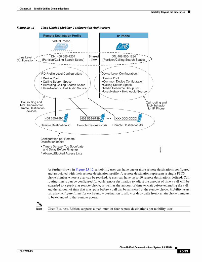
Chapter 25 Mobile Unified CommunicationsMobility Beyond the Enterprise
Figure 25-12 Cisco Unified Mobility Configuration Architecture
As further shown in Figure 25-12, a mobility user can have one or more remote destinations configured and associated with their remote destination profile. A remote destination represents a single PSTN phone number where a user can be reached. A user can have up to 10 remote destinations defined. Call routing timers can be configured for each remote destination to adjust the amount of time a call will be extended to a particular remote phone, as well as the amount of time to wait before extending the call and the amount of time that must pass before a call can be answered at the remote phone. Mobility users can also configure filters for each remote destination to allow or deny calls from certain phone numbers to be extended to that remote phone.
Note Cisco Business Edition supports a maximum of four remote destinations per mobility user.
1919
59
Configuration per RemoteDestination basis:
Timers (Answer Too Soon/Late and Delay Before Ringing) Allowed/Blocked Access Lists
IP IP
Remote Destination Profile
Line LevelConfiguration
DN: 408 555-1234(Partition/Calling Search Space)
DN: 408 555-1234(Partition/Calling Search Space)
SharedLine
RD Profile Level Configuration:
Device Pool Calling Search Space Rerouting Calling Search Space User/Network Hold Audio Source
Device Level Configuration:
Device Pool Common Device Configuration Calling Search Space Media Resource Group List User/Network Hold Audio Source
Call routing andMoH behavior for
Remote Destinationdevices
Call routing andMoH behaviorfor IP Phone
408 555-7890
Remote Destination #1
408 555-6789 XXX XXX-XXXX
Remote Destination #2 Remote Destination #3
IP Phone
Virtual Phone
25-33Cisco Unified Communications System 9.0 SRND
OL-27282-05
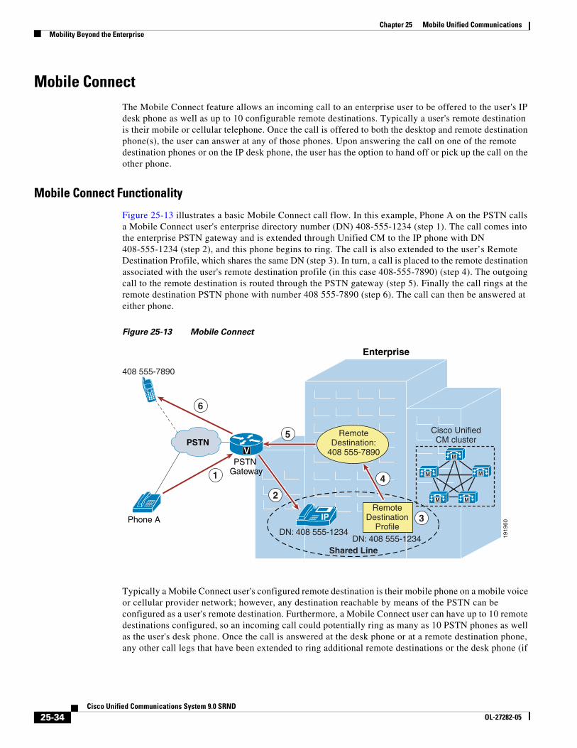
Chapter 25 Mobile Unified CommunicationsMobility Beyond the Enterprise
Mobile ConnectThe Mobile Connect feature allows an incoming call to an enterprise user to be offered to the user's IP desk phone as well as up to 10 configurable remote destinations. Typically a user's remote destination is their mobile or cellular telephone. Once the call is offered to both the desktop and remote destination phone(s), the user can answer at any of those phones. Upon answering the call on one of the remote destination phones or on the IP desk phone, the user has the option to hand off or pick up the call on the other phone.
Mobile Connect Functionality
Figure 25-13 illustrates a basic Mobile Connect call flow. In this example, Phone A on the PSTN calls a Mobile Connect user's enterprise directory number (DN) 408-555-1234 (step 1). The call comes into the enterprise PSTN gateway and is extended through Unified CM to the IP phone with DN 408-555-1234 (step 2), and this phone begins to ring. The call is also extended to the user’s Remote Destination Profile, which shares the same DN (step 3). In turn, a call is placed to the remote destination associated with the user's remote destination profile (in this case 408-555-7890) (step 4). The outgoing call to the remote destination is routed through the PSTN gateway (step 5). Finally the call rings at the remote destination PSTN phone with number 408 555-7890 (step 6). The call can then be answered at either phone.
Figure 25-13 Mobile Connect
Typically a Mobile Connect user's configured remote destination is their mobile phone on a mobile voice or cellular provider network; however, any destination reachable by means of the PSTN can be configured as a user's remote destination. Furthermore, a Mobile Connect user can have up to 10 remote destinations configured, so an incoming call could potentially ring as many as 10 PSTN phones as well as the user's desk phone. Once the call is answered at the desk phone or at a remote destination phone, any other call legs that have been extended to ring additional remote destinations or the desk phone (if
1919
60
6
5
4
3
2
1
Shared Line
408 555-7890
RemoteDestination
Profile
RemoteDestination:
408 555-7890PSTN
M
M
M M
M
IP
Enterprise
Phone A
PSTN Gateway
V
DN: 408 555-1234DN: 408 555-1234
Cisco UnifiedCM cluster
25-34Cisco Unified Communications System 9.0 SRND
OL-27282-05
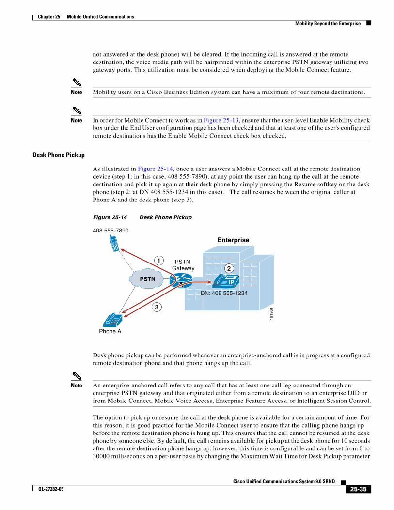
Chapter 25 Mobile Unified CommunicationsMobility Beyond the Enterprise
not answered at the desk phone) will be cleared. If the incoming call is answered at the remote destination, the voice media path will be hairpinned within the enterprise PSTN gateway utilizing two gateway ports. This utilization must be considered when deploying the Mobile Connect feature.
Note Mobility users on a Cisco Business Edition system can have a maximum of four remote destinations.
Note In order for Mobile Connect to work as in Figure 25-13, ensure that the user-level Enable Mobility check box under the End User configuration page has been checked and that at least one of the user's configured remote destinations has the Enable Mobile Connect check box checked.
Desk Phone Pickup
As illustrated in Figure 25-14, once a user answers a Mobile Connect call at the remote destination device (step 1: in this case, 408 555-7890), at any point the user can hang up the call at the remote destination and pick it up again at their desk phone by simply pressing the Resume softkey on the desk phone (step 2: at DN 408 555-1234 in this case). The call resumes between the original caller at Phone A and the desk phone (step 3).
Figure 25-14 Desk Phone Pickup
Desk phone pickup can be performed whenever an enterprise-anchored call is in progress at a configured remote destination phone and that phone hangs up the call.
Note An enterprise-anchored call refers to any call that has at least one call leg connected through an enterprise PSTN gateway and that originated either from a remote destination to an enterprise DID or from Mobile Connect, Mobile Voice Access, Enterprise Feature Access, or Intelligent Session Control.
The option to pick up or resume the call at the desk phone is available for a certain amount of time. For this reason, it is good practice for the Mobile Connect user to ensure that the calling phone hangs up before the remote destination phone is hung up. This ensures that the call cannot be resumed at the desk phone by someone else. By default, the call remains available for pickup at the desk phone for 10 seconds after the remote destination phone hangs up; however, this time is configurable and can be set from 0 to 30000 milliseconds on a per-user basis by changing the Maximum Wait Time for Desk Pickup parameter
1919
613
21
408 555-7890
VPSTN IP
Enterprise
Phone A
PSTN Gateway
DN: 408 555-1234
25-35Cisco Unified Communications System 9.0 SRND
OL-27282-05
Chapter 25 Mobile Unified CommunicationsMobility Beyond the Enterprise
under the End User configuration page. Desk phone pickup can also be performed after invoking the mid-call hold feature at the remote destination phone. However, in these cases, the Maximum Wait Time for Desk Pickup parameter setting has no effect on the amount of time the call will be available for pickup. A call placed on mid-call hold will remain on hold and be available for desk phone pickup until manually resumed at either the remote or desktop phone.
Another method for performing desk phone pickup is to use the mid-call session handoff feature. This mid-call feature is invoked by manually keying *74, the default enterprise feature access code for session handoff, which in turn generates a DTMF sequence back to Unified CM. When this feature is invoked, Unified CM sends a new call to the user's enterprise desk phone. Once this new call is flashing or ringing at the desk phone, the user then must answer the call to complete the session handoff.
The benefit of this desk phone pickup method over other methods (such as hanging up the call at the mobile phone or using the mid-call hold feature) is that the conversation between the user and the far-end phone is maintained throughout the handoff process. Once the *74 sequence has been keyed, the user can continue the conversation because the handoff call is sent to the user's desk phone. When the user answers the call at the desk phone, the call legs are shuffled so that the call leg to the far-end is connected to the new call leg created at the desk phone, thus resulting in an uninterrupted or near-instantaneous cut-through of the audio path. The original call leg at the mobile device is subsequently cleared.
Unlike the hang-up method for invoking desk phone pickup, where the end-user’s Maximum Wait Time for Desk Pickup setting determines how long the call will be available for pickup at the desk phone, with session handoff the Session Handoff Alerting Timer service parameter determines the amount of time the call will ring or flash at the desk phone before the handoff call is cleared. The default handoff alerting time is 10 seconds. Further, with session handoff, any call forward settings configured on the desk phone do not get invoked. As a result, the handoff feature does not forward to voicemail or any other call-forward destination. If a call is not answered by the end of Session Handoff Alerting Timer period, then the call is cleared and the Remote In Use state is removed from the user's desk phone line. However, in this scenario the original call is maintained at the mobile phone.
For additional information about session handoff and other mid-call features, see Mid-Call Features, page 25-37.
Remote Destination Phone Pickup
Figure 25-15 illustrates Mobile Connect remote destination phone pickup functionality. Assuming Phone A calls the Mobile Connect user's enterprise DN 408 555-1234 and the call is answered at the user's desk phone and is in progress (step 1), the user must push the Mobility softkey. Assuming the Mobile Connect feature is enabled for this phone and remote destination pickup is available, the user presses the Select softkey (step 2). A call is generated to the user's remote destination phone (in this case, 408 555-7890), and the remote phone begins to ring. Once the call is answered at the remote phone, the call resumes between Phone A and the Mobile Connect user's remote phone with number 408 555-7890 (step 3).
25-36Cisco Unified Communications System 9.0 SRND
OL-27282-05
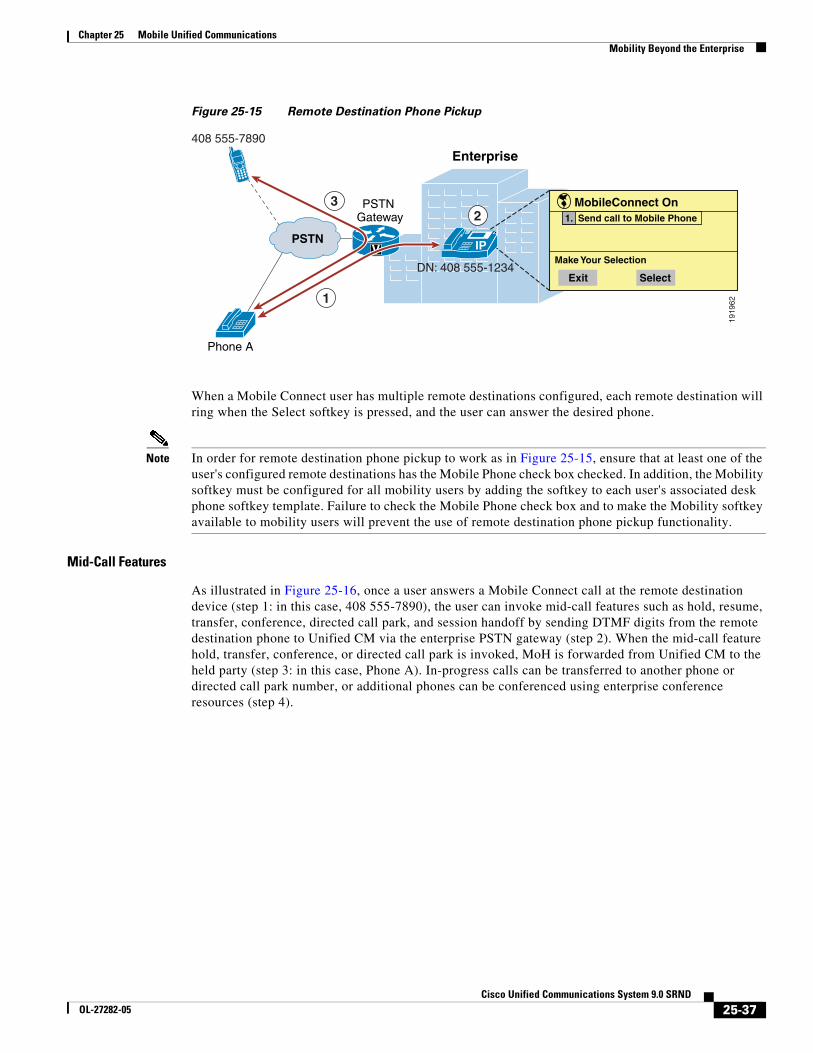
Chapter 25 Mobile Unified CommunicationsMobility Beyond the Enterprise
Figure 25-15 Remote Destination Phone Pickup
When a Mobile Connect user has multiple remote destinations configured, each remote destination will ring when the Select softkey is pressed, and the user can answer the desired phone.
Note In order for remote destination phone pickup to work as in Figure 25-15, ensure that at least one of the user's configured remote destinations has the Mobile Phone check box checked. In addition, the Mobility softkey must be configured for all mobility users by adding the softkey to each user's associated desk phone softkey template. Failure to check the Mobile Phone check box and to make the Mobility softkey available to mobility users will prevent the use of remote destination phone pickup functionality.
Mid-Call Features
As illustrated in Figure 25-16, once a user answers a Mobile Connect call at the remote destination device (step 1: in this case, 408 555-7890), the user can invoke mid-call features such as hold, resume, transfer, conference, directed call park, and session handoff by sending DTMF digits from the remote destination phone to Unified CM via the enterprise PSTN gateway (step 2). When the mid-call feature hold, transfer, conference, or directed call park is invoked, MoH is forwarded from Unified CM to the held party (step 3: in this case, Phone A). In-progress calls can be transferred to another phone or directed call park number, or additional phones can be conferenced using enterprise conference resources (step 4).
1919
62
32
1
408 555-7890
MobileConnect On
SelectExit
Make Your Selection
1. Send call to Mobile Phone
PSTN IP
Enterprise
Phone A
PSTN Gateway
DN: 408 555-1234
V
25-37Cisco Unified Communications System 9.0 SRND
OL-27282-05
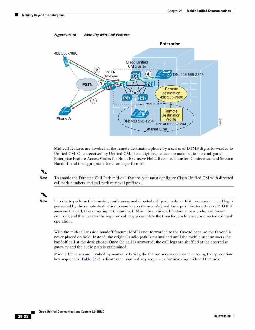
Chapter 25 Mobile Unified CommunicationsMobility Beyond the Enterprise
Figure 25-16 Mobility Mid-Call Feature
Mid-call features are invoked at the remote destination phone by a series of DTMF digits forwarded to Unified CM. Once received by Unified CM, these digit sequences are matched to the configured Enterprise Feature Access Codes for Hold, Exclusive Hold, Resume, Transfer, Conference, and Session Handoff, and the appropriate function is performed.
Note To enable the Directed Call Park mid-call feature, you must configure Cisco Unified CM with directed call park numbers and call park retrieval prefixes.
Note In order to perform the transfer, conference, and directed call park mid-call features, a second call leg is generated by the remote destination phone to a system-configured Enterprise Feature Access DID that answers the call, takes user input (including PIN number, mid-call feature access code, and target number), and then creates the required call leg to complete the transfer, conference, or directed call park operation.
With the mid-call session handoff feature, MoH is not forwarded to the far-end because the far-end is never placed on hold. Instead, the original audio path is maintained until the mobile user answers the handoff call at the desk phone. Once the call is answered, the call legs are shuffled at the enterprise gateway and the audio path is maintained.
Mid-call features are invoked by manually keying the feature access codes and entering the appropriate key sequences. Table 25-2 indicates the required key sequences for invoking mid-call features.
1919
63
4
3
2
Shared Line
408 555-7890
PSTN
M
M
M M
M
IP
Enterprise
Phone A
V
DN: 408 555-1234DN: 408 555-1234
Cisco UnifiedCM cluster
RemoteDestination:
408 555-7890
IP DN: 408 555-2345
RemoteDestination
Profile
1
PSTNGateway
25-38Cisco Unified Communications System 9.0 SRND
OL-27282-05
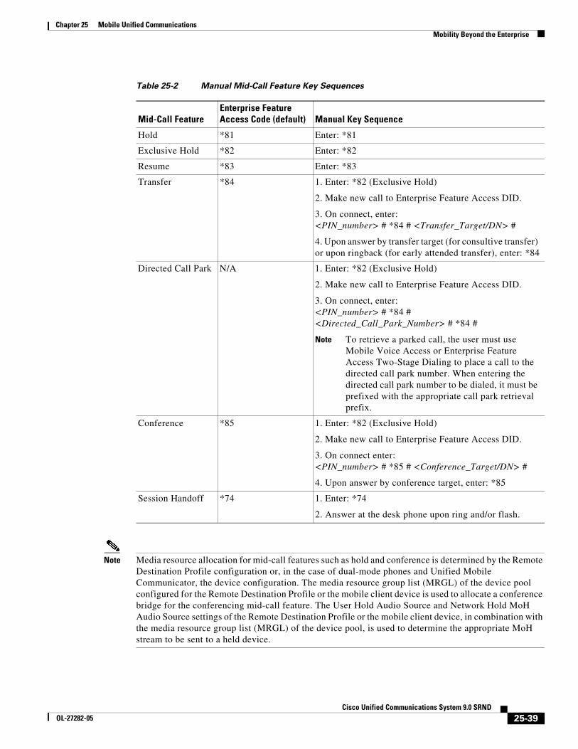
Chapter 25 Mobile Unified CommunicationsMobility Beyond the Enterprise
Note Media resource allocation for mid-call features such as hold and conference is determined by the Remote Destination Profile configuration or, in the case of dual-mode phones and Unified Mobile Communicator, the device configuration. The media resource group list (MRGL) of the device pool configured for the Remote Destination Profile or the mobile client device is used to allocate a conference bridge for the conferencing mid-call feature. The User Hold Audio Source and Network Hold MoH Audio Source settings of the Remote Destination Profile or the mobile client device, in combination with the media resource group list (MRGL) of the device pool, is used to determine the appropriate MoH stream to be sent to a held device.
Table 25-2 Manual Mid-Call Feature Key Sequences
Mid-Call FeatureEnterprise Feature Access Code (default) Manual Key Sequence
Hold *81 Enter: *81
Exclusive Hold *82 Enter: *82
Resume *83 Enter: *83
Transfer *84 1. Enter: *82 (Exclusive Hold)
2. Make new call to Enterprise Feature Access DID.
3. On connect, enter: <PIN_number> # *84 # <Transfer_Target/DN> #
4. Upon answer by transfer target (for consultive transfer) or upon ringback (for early attended transfer), enter: *84
Directed Call Park N/A 1. Enter: *82 (Exclusive Hold)
2. Make new call to Enterprise Feature Access DID.
3. On connect, enter:<PIN_number> # *84 # <Directed_Call_Park_Number> # *84 #
Note To retrieve a parked call, the user must use Mobile Voice Access or Enterprise Feature Access Two-Stage Dialing to place a call to the directed call park number. When entering the directed call park number to be dialed, it must be prefixed with the appropriate call park retrieval prefix.
Conference *85 1. Enter: *82 (Exclusive Hold)
2. Make new call to Enterprise Feature Access DID.
3. On connect enter: <PIN_number> # *85 # <Conference_Target/DN> #
4. Upon answer by conference target, enter: *85
Session Handoff *74 1. Enter: *74
2. Answer at the desk phone upon ring and/or flash.
25-39Cisco Unified Communications System 9.0 SRND
OL-27282-05
Chapter 25 Mobile Unified CommunicationsMobility Beyond the Enterprise
Mobile Voicemail Avoidance with Single Enterprise Voicemail Box
An additional consideration with Cisco Unified Mobility Mobile Connect is mobile voicemail avoidance. The single enterprise voicemail box feature ensures that all unanswered enterprise business calls end up at the enterprise voicemail system. This prevents a user from having to check multiple mailboxes (enterprise, mobile, home, and so forth) for calls to their enterprise phone number that are unanswered. This feature provides two methods for avoiding mobile or non-enterprise voicemail:
• Timer Control method — With this method the system relies on a set of timers (one per remote destination) in conjunction with system call-forward timers to ensure that, when and if a call is forwarded to a voicemail system on ring-no-answer, the enterprise voicemail system receives the call.
• User Control method — With this method the system relies on a DTMF confirmation tone from the remote destination when the call is answered to determine if the call was received by the user or a non-enterprise voicemail system.
System settings determine whether the timer control or user control method is used. The method used can be set globally via the Voicemail Selection Policy service parameter or for individual remote destinations via the Single Number Reach Voicemail Policy. By default the system and all remote destinations use the timer control method
Timer Control Mobile Voicemail Avoidance
For this method, the system relies on a set of timers on the Remote Destination configuration page. The purpose of these timers is to ensure that, when and if a call is forwarded to a voicemail system on ring-no-answer, the call is forwarded to the enterprise voicemail system rather than any remote destination voicemail system. These timers in conjunction with other system forward-no-answer timers should be configured to avoid non-enterprise voicemail systems as follows:
• Ensure the system forward-no-answer time is shorter at the desk phone than at the remote destination phones.
To do so, ensure that the global Forward No Answer Timer field in Unified CM or the No Answer Ring Duration field under the individual phone line is configured with a value that is less than the amount of time a remote destination phone will ring before forwarding to the mobile voicemail system. In addition, the Delay Before Ringing Timer parameter under the Remote Destination configuration page can be used to delay the ringing of the remote destination phone in order to further lengthen the amount of time that must pass before a remote destination phone will forward to its own mobile voicemail box. However, when adjusting the Delay Before Ringing Timer parameter, take care to ensure that the global Unified CM Forward No Answer Timer (or the line-level No Answer Ringer Duration field) is set sufficiently high enough so that the mobility user has time to answer the call on the remote destination phone. The Delay Before Ringing Timer parameter can be set for each remote destination and is set to 4,000 milliseconds by default.
• Ensure that the remote destination device stops ringing before the incoming call is forwarded to the mobile voicemail system.
You can accomplish this with the Answer Too Soon and Answer Too Late timers for each remote destination. First the Answer Too Soon Timer parameter under the Remote Destination configuration page should be configured with a value that is more than the amount of time it takes a call extended to a powered-off or out-of-range mobile phone to be forwarded to the mobile voicemail system. By default this timer is set 1,500 milliseconds (or 1.5 seconds). If the call is answered before the Answer Too Soon Timer expires, the system will disconnect the call leg to the remote destination. This ensures that calls forwarded immediately to the mobile voicemail system will not be connected, but those answered by the user after ring-in are connected.
25-40Cisco Unified Communications System 9.0 SRND
OL-27282-05
Chapter 25 Mobile Unified CommunicationsMobility Beyond the Enterprise
Next configure the Answer Too Late Timer parameter under the Remote Destination configuration page with a value that is less than the amount of time that a remote destination phone will ring before forwarding to its voicemail box. By default this timer is set to 19,00 milliseconds (or 19 seconds). If the call is not answered before this timer expires, the system will disconnect the call leg to the remote destination. This ensures that the remote destination phone stops ringing before the call is forwarded to the mobile voicemail system.
Note Incoming calls to a remote destination that are manually diverted by the mobility user can end up in the mobile voicemail box if the manual diversion occurs after the Answer Too Soon timer has expired. To prevent this from happening, mobility users should be configured for the user control method or advised to ignore or silence the ringing of incoming calls they wish to divert to voicemail. This will ensure that unanswered calls always end up in the enterprise voicemail system.
Note In most deployment scenarios, the default Delay Before Ringing Timer, Answer Too Late Timer, and Answer Too Soon Timer values are sufficient and do not need to be changed.
User Control Mobile Voicemail Avoidance
For this method, the system relies on DTMF confirmation tone from the remote destination when the call is answered. If a DTMF tone is received by the system, then the system knows that the user answered the call and pressed a key to generate the DTMF tone. On the other hand, if the DTMF tone is not received by the system, the system assumes the call leg was answered by a non-enterprise voicemail system and it disconnects the call leg.
When the user control method is enabled, on answer the end user will hear an audio prompt requesting that they press a key pad button to generate a DTMF tone. By default the audio prompt is played to the user one second after the call is answered. The user may not hear the audio prompt if they press the keypad to generate a DTMF tone immediately upon answering. The audio prompt is played only on the remote destination call leg and therefore the far-end party will not hear this prompt. Once the audio prompt is played to the user, by default the system will wait 5 seconds to receive the DTMF tone. If the tone is not received, the system disconnects the call leg but continues to ring the user's other configured devices until the call is answered by the user or forwarded to the enterprise voicemail system.
Note The user control mobile voicemail avoidance method is completely dependent on successful relay of the DTMF tone from the remote destination on the mobile voice network or PSTN all the way to Unified CM. The DTMF tone must be sent out-of-band to Unified CM. If DTMF relay is not properly configured on the network and system, DTMF will not be received and all call legs to remote destinations relying on the user control method will be disconnected. The system administrator should ensure proper DTMF interoperation and relay across the enterprise telephony network prior to enabling the user control method. If DTMF cannot be effectively relayed from the PSTN to Unified CM, then the timer control mobile voicemail avoidance method should be used instead.
25-41Cisco Unified Communications System 9.0 SRND
OL-27282-05
Chapter 25 Mobile Unified CommunicationsMobility Beyond the Enterprise
Enabling and Disabling Mobile Connect
The Mobile Connect feature can be enabled or disabled by using one of the following methods:
• Cisco Unified CM Administration or Cisco Unified CM User Options pages
An administrator or user unchecks the Mobile Connect box to disable, or checks the Mobile Connect box to enable, the feature. This is done per remote destination.
• Mobile Voice Access or Enterprise Feature Access
A Mobility-enabled user dials into the Mobile Voice Access or Enterprise Feature Access DID and, after entering appropriate credentials, enters the digit 2 to enable or 3 to disable. With Mobile Voice Access, the user is prompted to enable or disable Mobile Connect for a single remote destination or all of their remote destinations. With Enterprise Feature Access, the user can enable or disable Mobile Connect only for the remote destination device from which they are calling.
• Desk phone Mobility softkey
The user presses the Mobility softkey when the phone is in the on-hook state and selects either Enable Mobile Connect or Disable Mobile Connect. With this method, Mobile Connect is enabled or disabled for all of the user's remote destinations.
Access Lists for Allowing or Blocking Mobile Connect Calls
Access lists can be configured within Cisco Unified CM and associated to a remote destination. Access lists are used to allow or block inbound calls (based on incoming caller ID) from being extended to a mobility-enabled user's remote destinations. Furthermore, these access lists are invoked based on the time of day.
Access lists are configured for mobility-enabled users as either blocked or allowed. Access lists contain one or more members or filters consisting of a specific number or number mask, and the filters are compared against the incoming caller ID of the calling party. In addition to containing specific number strings or number masks for matching caller ID, access lists can also contain a filter for incoming calls where the caller ID is not available or is set to private. A blocked access list contains an implicit "allow all" at the end of the list so that calls from any numbers entered in the access list will be blocked but calls from all other numbers will be allowed. An allowed access list contains an implicit "deny all" at the end of the list so that calls from any numbers entered in the access list will be allowed but calls from all other numbers will be blocked.
Once configured access lists are associated with a configured Ring Schedule under the Remote Destination configuration screen, the configured Ring Schedule in combination with the selected access list provides time-of-day call filtering for Mobile Connect calls on a per-remote-destination basis. Access lists and Ring Schedules can be configured and associated to a remote destination by an administrator using the Cisco Unified CM Administration interface or by an end user using the Cisco Unified CM User Options interface.
Mobile Connect Architecture
The architecture of the Mobile Connect feature is as important to understand as its functionality. Figure 25-17 depicts the message flows and architecture required for Mobile Connect. The following sequence of interactions and events can occur between Unified CM, the Mobile Connect user, and the Mobile Connect user's desk phone:
1. The Mobile Connect phone user who wishes to either enable or disable the Mobile Connect feature or to pick up an in-progress call on their remote destination phone pushes the Mobility softkey on their desk phone (see step 1 in Figure 25-17).
25-42Cisco Unified Communications System 9.0 SRND
OL-27282-05
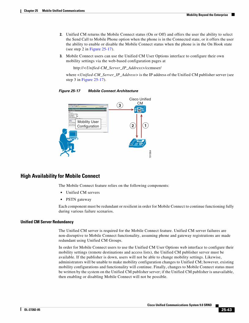
Chapter 25 Mobile Unified CommunicationsMobility Beyond the Enterprise
2. Unified CM returns the Mobile Connect status (On or Off) and offers the user the ability to select the Send Call to Mobile Phone option when the phone is in the Connected state, or it offers the user the ability to enable or disable the Mobile Connect status when the phone is in the On Hook state (see step 2 in Figure 25-17).
3. Mobile Connect users can use the Unified CM User Options interface to configure their own mobility settings via the web-based configuration pages at
http://<Unified-CM_Server_IP_Address>/ccmuser/
where <Unified-CM_Server_IP_Address> is the IP address of the Unified CM publisher server (see step 3 in Figure 25-17).
Figure 25-17 Mobile Connect Architecture
High Availability for Mobile Connect
The Mobile Connect feature relies on the following components:
• Unified CM servers
• PSTN gateway
Each component must be redundant or resilient in order for Mobile Connect to continue functioning fully during various failure scenarios.
Unified CM Server Redundancy
The Unified CM server is required for the Mobile Connect feature. Unified CM server failures are non-disruptive to Mobile Connect functionality, assuming phone and gateway registrations are made redundant using Unified CM Groups.
In order for Mobile Connect users to use the Unified CM User Options web interface to configure their mobility settings (remote destinations and access lists), the Unified CM publisher server must be available. If the publisher is down, users will not be able to change mobility settings. Likewise, administrators will be unable to make mobility configuration changes to Unified CM; however, existing mobility configurations and functionality will continue. Finally, changes to Mobile Connect status must be written by the system on the Unified CM publisher server; if the Unified CM publisher is unavailable, then enabling or disabling Mobile Connect will not be possible.
1919
64
12Mobility UserConfiguration
IP
M
Cisco UnifiedCM3
25-43Cisco Unified Communications System 9.0 SRND
OL-27282-05
Chapter 25 Mobile Unified CommunicationsMobility Beyond the Enterprise
PSTN Gateway Redundancy
Because the Mobile Connect feature relies on the ability to extend additional call legs to the PSTN to reach the Mobile Connect users’ remote destination phones, PSTN gateway redundancy is important. Should a PSTN gateway fail or be out of capacity, the Mobile Connect call cannot complete. Typically, enterprise IP telephony dial plans provide redundancy for PSTN access by providing physical gateway redundancy and call re-routing capabilities as well as enough capacity to handle expected call activity. Assuming that Unified CM has been configured with sufficient capacity, multiple gateways, and route group and route list constructs for call routing resiliency, the Mobile Connect feature can rely on this redundancy for uninterrupted functionality.
Mobile Voice Access and Enterprise Feature AccessMobile Voice Access (also referred to as System Remote Access) and Enterprise Feature Access two-stage dialing are features built on top of the Mobile Connect application. Both features allow a mobility-enabled user who is outside the enterprise to make a call as though they are directly connected to Unified CM. This functionality is commonly referred to as Direct Inward System Access (DISA) in traditional telephony environments. These features benefit the enterprise by limiting toll charges and consolidating phone billing directly to the enterprise rather than billing to each mobile user. In addition, these features allow the users to mask their mobile phone or remote destination numbers when sending outbound caller ID. Instead, the user's enterprise directory number is sent as caller ID. This ensures that returned calls to the user are made to the enterprise number, thus resulting in enterprise call anchoring. These features also enable mobile users to dial internal extensions or non-DID enterprise numbers that would not normally be reachable from outside the enterprise.
Mobile Voice Access is accessed by calling a system-configured DID number that is answered and handled by an H.323 or SIP VoiceXML (VXML) gateway. The VoiceXML gateway plays interactive voice response (IVR) prompts to the Mobile Voice Access user, requesting user authentication and input of a number to be dialed via the user phone keypad.
Enterprise Feature Access functionality includes the previously discussed mid-call transfer and conference features as well as two-stage dialing functionality. Two-stage dialing works the same way as Mobile Voice Access, but without the IVR prompts. The system-configured Enterprise Feature Access DID is answered by Unified CM. The user then uses the phone keypad or Smart Phone softkeys to input authentication and the number to be dialed. These inputs are received without prompts.
With both the Mobile Voice Access and Enterprise Feature Access two-stage dialing features, once the call to the input number is connected, users can invoke mid-call features or pick up the call on their desk phones just as with a Mobile Connect calls. This is possible because the call is anchored at the enterprise gateway.
Mobile Voice Access IVR VoiceXML Gateway URL
The Mobile Voice Access feature requires the Unified CM VoiceXML application to reside on the H.323 or SIP gateway. The URL used to load this application is:
http://<Unified-CM-Publisher_IP-Address>:8080/ccmivr/pages/IVRMainpage.vxml
where <Unified-CM-Publisher_IP-Address> is the IP address of the Unified CM publisher node.
25-44Cisco Unified Communications System 9.0 SRND
OL-27282-05
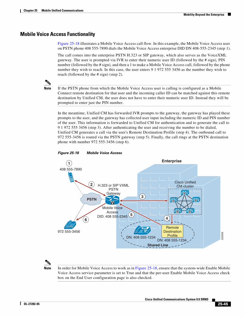
Chapter 25 Mobile Unified CommunicationsMobility Beyond the Enterprise
Mobile Voice Access Functionality
Figure 25-18 illustrates a Mobile Voice Access call flow. In this example, the Mobile Voice Access user on PSTN phone 408 555-7890 dials the Mobile Voice Access enterprise DID DN 408-555-2345 (step 1).
The call comes into the enterprise PSTN H.323 or SIP gateway, which also serves as the VoiceXML gateway. The user is prompted via IVR to enter their numeric user ID (followed by the # sign), PIN number (followed by the # sign), and then a 1 to make a Mobile Voice Access call, followed by the phone number they wish to reach. In this case, the user enters 9 1 972 555 3456 as the number they wish to reach (followed by the # sign) (step 2).
Note If the PSTN phone from which the Mobile Voice Access user is calling is configured as a Mobile Connect remote destination for that user and the incoming caller ID can be matched against this remote destination by Unified CM, the user does not have to enter their numeric user ID. Instead they will be prompted to enter just the PIN number.
In the meantime, Unified CM has forwarded IVR prompts to the gateway, the gateway has played these prompts to the user, and the gateway has collected user input including the numeric ID and PIN number of the user. This information is forwarded to Unified CM for authentication and to generate the call to 9 1 972 555 3456 (step 3). After authenticating the user and receiving the number to be dialed, Unified CM generates a call via the user's Remote Destination Profile (step 4). The outbound call to 972 555-3456 is routed via the PSTN gateway (step 5). Finally, the call rings at the PSTN destination phone with number 972 555-3456 (step 6).
Figure 25-18 Mobile Voice Access
Note In order for Mobile Voice Access to work as in Figure 25-18, ensure that the system-wide Enable Mobile Voice Access service parameter is set to True and that the per-user Enable Mobile Voice Access check box on the End User configuration page is also checked.
2529
396
2
1
Shared Line
408 555-7890
RemoteDestination
Profile
5
3PSTN
M
M
M M
M
IP
Enterprise
972 555-3456
V
DN: 408 555-1234DN: 408 555-1234
Cisco UnifiedCM cluster
4
H.323 or SIP VXMLPSTN
Gateway
Mobile VoiceAccess
DID: 408 555-2345
25-45Cisco Unified Communications System 9.0 SRND
OL-27282-05
Chapter 25 Mobile Unified CommunicationsMobility Beyond the Enterprise
Note The Mobile Voice Access feature relies on the Cisco Unified Mobile Voice Access Service, which must be activated manually from the Unified CM Serviceability configuration page. This service can be activated on the publisher node only.
Mobile Voice Access Using Hairpinning
In deployments where the enterprise PSTN gateways are not using H.323 or SIP, Mobile Voice Access functionality can still be provided using hairpinning on a separate gateway running H.323. Mobile Voice Access using hairpinning relies on off-loading the VoiceXML functionality to a separate H.323 gateway. Figure 25-19 illustrates a Mobile Voice Access call flow using hairpinning. In this example, just as in the previous example, the Mobile Voice Access user on PSTN phone 408 555-7890 dials the Mobile Voice Access enterprise DID DN 408-555-2345 (step 1). The call comes into the enterprise PSTN gateway (step 2) and is forwarded to Unified CM for call handling (step 3). Unified CM next routes the inbound call to the H.323 VoiceXML gateway (step 4). The user is then prompted by IVR to enter their numeric user ID, PIN, and then a 1 to make a Mobile Voice Access call, followed by the phone number they wish to reach. Again the user enters 9 1 972 555 3456 as the number they wish to reach (followed by the # sign).
Note When using Mobile Voice Access with hairpinning, users calling into the system will not be identified automatically by their caller ID. Instead, users will have to key in their remote destination number manually prior to entering their PIN. The reason the user is not automatically identified is that, for hairpinning deployments, the PSTN gateway must first route the call to Unified CM to reach the hairpinned Mobile Voice Access gateway. Because the call is routed to Unified CM first, the conversion of the calling number from a mobile number to an enterprise directory number occurs prior to the call being handled by the Mobile Voice Access gateway. This results in the Mobile Voice Access gateway being unable to match the calling number with a configured remote destination, and therefore the system prompts the user to enter their remote destination number. This is unique to hairpinning deployments; with normal Mobile Voice Access flows, the PSTN gateway does not have to route the call to Unified CM first in order to access Mobile Voice Access because the functionality is available on the local gateway.
In the meantime, the H.323 VoiceXML gateway collects and forwards the user input to Unified CM and then plays the forwarded IVR prompts to the PSTN gateway and the Mobile Voice Access user. Unified CM in turn receives user input, authenticates the user, and forwards appropriate IVR prompts to the H.323 VoiceXML gateway based on user input (step 5). After receiving the number to be dialed, Unified CM generates a call using the user's Remote Destination Profile (step 6). The outbound call to 972 555-3456 is routed through the PSTN gateway (step 7). Finally, the call rings at the PSTN destination phone with number 972 555-3456 (step 8).
25-46Cisco Unified Communications System 9.0 SRND
OL-27282-05
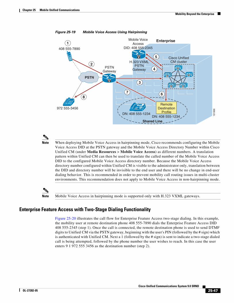
Chapter 25 Mobile Unified CommunicationsMobility Beyond the Enterprise
Figure 25-19 Mobile Voice Access Using Hairpinning
Note When deploying Mobile Voice Access in hairpinning mode, Cisco recommends configuring the Mobile Voice Access DID at the PSTN gateway and the Mobile Voice Access Directory Number within Cisco Unified CM (under Media Resources > Mobile Voice Access) as different numbers. A translation pattern within Unified CM can then be used to translate the called number of the Mobile Voice Access DID to the configured Mobile Voice Access directory number. Because the Mobile Voice Access directory number configured within Unified CM is visible to the administrator only, translation between the DID and directory number will be invisible to the end user and there will be no change in end-user dialing behavior. This is recommended in order to prevent mobility call routing issues in multi-cluster environments. This recommendation does not apply to Mobile Voice Access in non-hairpinning mode.
Note Mobile Voice Access in hairpinning mode is supported only with H.323 VXML gateways.
Enterprise Feature Access with Two-Stage Dialing Functionality
Figure 25-20 illustrates the call flow for Enterprise Feature Access two-stage dialing. In this example, the mobility user at remote destination phone 408 555-7890 dials the Enterprise Feature Access DID 408 555-2345 (step 1). Once the call is connected, the remote destination phone is used to send DTMF digits to Unified CM via the PSTN gateway, beginning with the user's PIN (followed by the # sign) which is authenticated with Unified CM. Next a 1 (followed by the # sign) is sent to indicate a two-stage dialed call is being attempted, followed by the phone number the user wishes to reach. In this case the user enters 9 1 972 555 3456 as the destination number (step 2).
1919
66
8
2
1
Shared Line
408 555-7890
RemoteDestination
Profile
7
3PSTN
IP
Enterprise
972 555-3456
V
DN: 408 555-1234DN: 408 555-1234
Cisco UnifiedCM cluster
6
H.323 VXMLPSTN
Gateway
Mobile VoiceAccess
DID: 408 555-2345
PSTNGateway
V
4 M
M
M M
M
5
25-47Cisco Unified Communications System 9.0 SRND
OL-27282-05
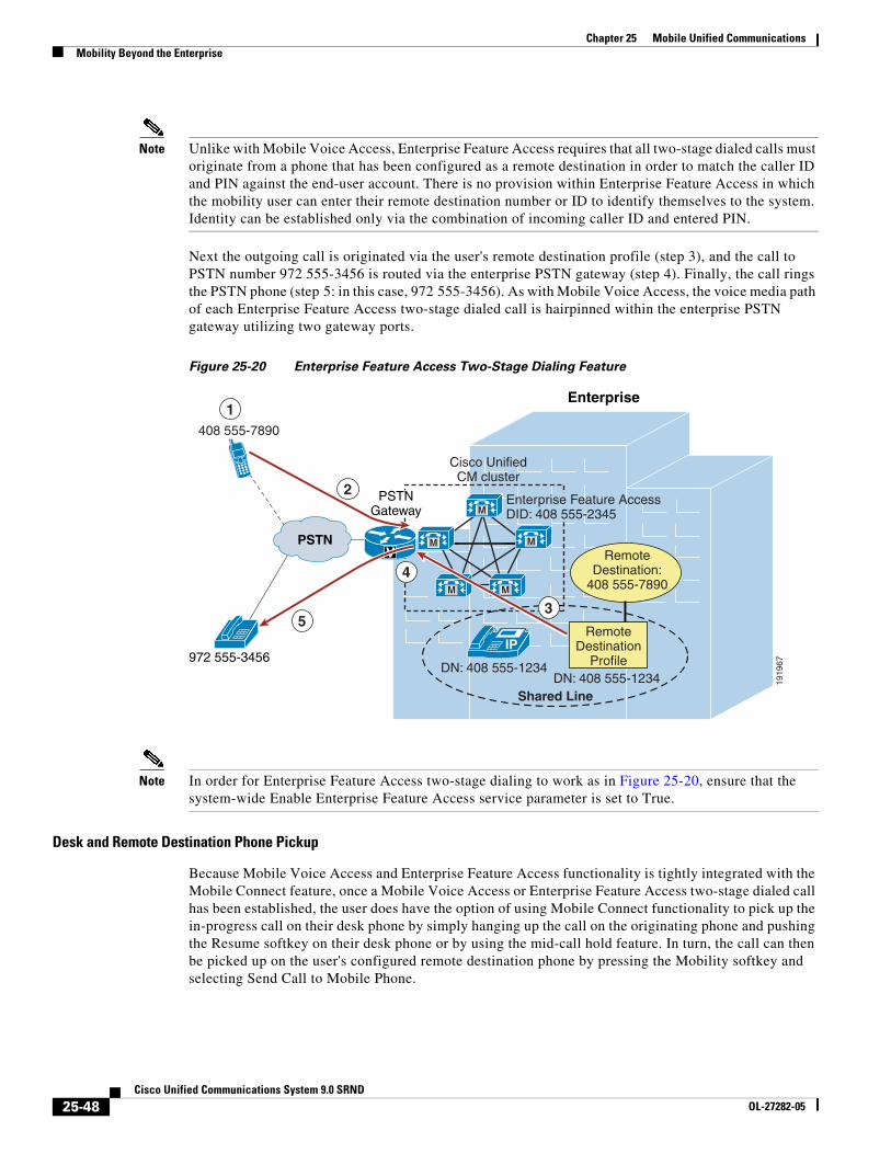
Chapter 25 Mobile Unified CommunicationsMobility Beyond the Enterprise
Note Unlike with Mobile Voice Access, Enterprise Feature Access requires that all two-stage dialed calls must originate from a phone that has been configured as a remote destination in order to match the caller ID and PIN against the end-user account. There is no provision within Enterprise Feature Access in which the mobility user can enter their remote destination number or ID to identify themselves to the system. Identity can be established only via the combination of incoming caller ID and entered PIN.
Next the outgoing call is originated via the user's remote destination profile (step 3), and the call to PSTN number 972 555-3456 is routed via the enterprise PSTN gateway (step 4). Finally, the call rings the PSTN phone (step 5: in this case, 972 555-3456). As with Mobile Voice Access, the voice media path of each Enterprise Feature Access two-stage dialed call is hairpinned within the enterprise PSTN gateway utilizing two gateway ports.
Figure 25-20 Enterprise Feature Access Two-Stage Dialing Feature
Note In order for Enterprise Feature Access two-stage dialing to work as in Figure 25-20, ensure that the system-wide Enable Enterprise Feature Access service parameter is set to True.
Desk and Remote Destination Phone Pickup
Because Mobile Voice Access and Enterprise Feature Access functionality is tightly integrated with the Mobile Connect feature, once a Mobile Voice Access or Enterprise Feature Access two-stage dialed call has been established, the user does have the option of using Mobile Connect functionality to pick up the in-progress call on their desk phone by simply hanging up the call on the originating phone and pushing the Resume softkey on their desk phone or by using the mid-call hold feature. In turn, the call can then be picked up on the user's configured remote destination phone by pressing the Mobility softkey and selecting Send Call to Mobile Phone.
1919
67
2
Shared Line
408 555-7890
PSTN
M
M
M M
M
IP
Enterprise
972 555-3456
V
DN: 408 555-1234DN: 408 555-1234
Cisco UnifiedCM cluster
RemoteDestination:
408 555-7890
RemoteDestination
Profile
1
PSTNGateway
3
4
Enterprise Feature AccessDID: 408 555-2345
5
25-48Cisco Unified Communications System 9.0 SRND
OL-27282-05
Chapter 25 Mobile Unified CommunicationsMobility Beyond the Enterprise
Enabling and Disabling Mobile Connect
In addition to providing users of Mobile Voice Access and Enterprise Feature Access with the ability to make calls from the PSTN as though they are within the enterprise, the functionality provided by Mobile Voice Access on the H.323 or SIP VoiceXML gateway and provided by Enterprise Feature Access also gives users the ability to remotely enable and disable their Mobile Connect functionality for each remote destination via their phone keypad. Rather than entering a 1 to make a call, users enter a 2 to turn the Mobile Connect feature on and a 3 to turn the Mobile Connect feature off.
If a user has more than one remote destination configured when using Mobile Voice Access, they are prompted to key in the remote destination phone number for which they wish to enable or disable the Mobile Connect feature. When using Enterprise Feature Access, a user can enable or disable Mobile Connect only for the remote destination phone from which they are calling.
Note When the Enable Mobile Voice Access service parameter is set to False, resulting in an inability to make two-stage dialed calls, Mobile Voice Access still provides users with the ability to enable and disable mobile connect remotely. As long as the Mobile Voice Access Directory Number has been configured on the system, the user's account has been enabled for Mobile Voice Access, and the Cisco Unified Mobile Voice Access service is running on the publisher, a calling user can still enable or disable Mobile Connect.
Mobile Voice Access and Enterprise Feature Access Number Blocking
Administrators might want to prevent users of Mobile Voice Access and Enterprise Feature Access two-stage dialing from dialing certain numbers when using these features. In order to restrict or block calls to certain numbers when using these features for off-net calls, a comma-separated list of those numbers can be configured in the System Remote Access Blocked Numbers service parameter field. Once this parameter is configured with blocked numbers, those numbers will not be reachable from a user's remote destination phone when using Mobile Voice Access or Enterprise Feature Access features. Numbers that administrators might want to block can include emergency numbers such as 911. When configuring blocked numbers, ensure they are configured as they would be dialed by an enterprise user, with appropriate prefixes or steering digits. For example, if an emergency number is to be blocked and the emergency number is dialed by system users as 9911, then the number configured in the System Remote Access Blocked Numbers field should be 9911.
Access Numbers for Mobile Voice Access and Enterprise Feature Access
While the Unified CM system allows the configuration of only a single Mobile Voice Access Directory Number, this does not preclude the use of multiple externally facing numbers that can access these internally configured numbers. For example, consider a system deployed in the US in New York with a remote site in San Jose as well as an overseas site in London. Even though the system may have the Mobile Voice Access directory number configured as 555-1234, the gateways at each location can be configured to map a local or toll-free DID number to this Mobile Voice Access directory number. For example, the gateway in New York may have DIDs of +1 212 555 1234 and +1 800 555 1234, which both map to the Mobile Voice Access number, while the gateway in San Jose has a DID of +1 408 666 5678 and the gateway in London has a DID of +44 208 777 0987, which also map to the Mobile Voice Access number of the system. The Unified CM system does permit the configuration of multiple Enterprise Feature Access Numbers so that location-specific system access numbers can be configured for each geographic location of the deployment. This enables local or toll-free Enterprise Feature Access two-stage dialing functionality for all users regardless of geographic location.
25-49Cisco Unified Communications System 9.0 SRND
OL-27282-05
Chapter 25 Mobile Unified CommunicationsMobility Beyond the Enterprise
By acquiring multiple local or toll-free DID numbers, system administrators can ensure that two-stage dialed calls will always originate as a call into the system that is either local or toll-free, thus providing further reductions in telephony costs.
Remote Destination Configuration and Caller ID Matching
When authenticating users for Mobile Voice Access and Enterprise Feature Access two-stage dialing functionality as well as the DTMF-based mid-call features Transfer and Conference, the caller ID of the calling remote destination phone is matched against all remote destinations configured within the system. Matching of this caller ID depends on a number of factors, including how the remote destination numbers are configured, whether digit prefixing is required to include PSTN steering digits on the system, and whether the Matching Caller ID with Remote Destination parameter is set to Partial or Complete Match. In all cases, the requirement is to be able to uniquely identify each mobility user based on the their remote destination number or numbers. For this reason, it is critical not only that remote destination numbers be configured uniquely within the system, but also that inbound caller ID matching (whether using complete or partial matching) must always uniquely correspond to a single remote destination. If a single or unique match is not found, caller ID matching will fail.
To control the nature of this matching, consider the following two approaches.
Using Complete Caller ID Matching
With this approach, remote destination numbers are configured exactly as the caller ID would be presented from the PSTN. For example, if the caller ID from the PSTN for a remote destination phone is presented to the system as 4085557890, then this number should be configured on the Remote Destination configuration page.
In order to route Mobile Connect calls appropriately to this remote destination, it is necessary to configure the dial plan to use either +E.164 dialing methods or a digit prefix mechanism to prefix necessary PSTN access codes and other required digits. For example, if you are not using a global +E.164 dial plan and assuming a 9 or other PSTN steering digits or country codes are required to reach the PSTN when dialing calls from the enterprise, then digit prefixing must be configured to add the appropriate PSTN steering digit and country code to the beginning of the configured remote destination number. Digit prefixing should be facilitated by using translation patterns, route patterns, or route list constructs within the Unified CM system. When using this complete match approach and a digit prefixing method, the Matching Caller ID with Remote Destination parameter should be left at the default setting of Complete Match.
Application Dial Rules may also be used to provide digit prefixing in these scenarios. However, it is worth noting that Application Dial Rules are applied based on called digit-string length and cannot be partitioned, meaning that they are applied globally across the system. This severely limits the use of Application Dial Rules, especially in scenarios where multiple dialing domains (for example, different countries) need to be supported on a single Unified CM cluster.
Note Not only are Application Dial Rules applied to Mobile Connect, Mobile Voice Access, and Enterprise Feature Access calls, but they are also applied to calls made with Cisco WebDialer, Cisco Unified CM Assistant, and Cisco Jabber applications. For this reason, exercise care when configuring these rules to ensure that dialing behavior across all applications is as expected.
The recommended dial plan approach is always to globalize the caller ID to +E.164 on ingress from the PSTN and always to configure remote destinations as +E.164. This will guarantee that the caller ID from the PSTN (after normalization) will always provide a unique match when compared against all configured remote destinations. Combined with a dial plan supporting +E.164 dialing, this eliminates the need for digit prefixing and ensures unique identification of remote destination users and numbers
25-50Cisco Unified Communications System 9.0 SRND
OL-27282-05
Chapter 25 Mobile Unified CommunicationsMobility Beyond the Enterprise
even when supporting multiple international numbering plans. Because the recommended dial plan approach is to globalize the caller ID on ingress and localize on egress according to trunk requirements and/or user expectations, using the unmodified caller ID as presented from the PSTN is not compatible with this approach.
Using Partial Caller ID Matching
With this approach, remote destinations are configured as they would be dialed from the system to the PSTN. For example, if the number for the remote destination is 14085557890 and PSTN access from the system requires a 9, then this number should be configured on the Remote Destination configuration page as 914085557890. This approach precludes the need for configuration of a digit prefixing mechanism on the system, but it requires setting the Matching Caller ID with Remote Destination service parameter to Partial Match and setting the Number of Digits for Caller ID Partial Match to the appropriate number of consecutive digits that should be matched against the remote destination caller ID. For example, if the caller ID for a remote destination is 14085557890 and the remote destination is configured as 914085557890, then the Number of Digits for Caller ID Partial Match would ideally be set to 10 or 11. In this example, this parameter could be set to a lower number of digits; however, always ensure that enough consecutive digits are matched so that all configured remote destinations in the system are matched uniquely. If there is no exact match or if more than one configured remote destination number is matched when using partial caller ID matching, the system treats this as if there is no matching remote destination number, thus requiring the user to enter their remote destination number/ID manually in the case of Mobile Voice Access before providing their PIN. With Enterprise Feature Access, there is no mechanism for the user to enter their remote destination number; therefore, when using this functionality, ensure that only unique matches occur.
Note If the PSTN service provider sends variable-length caller IDs, using partial caller ID matching is not recommended because ensuring a unique caller ID match for each inbound call might not be possible. In these scenarios, using complete caller ID matching and/or a +E.164 dial plan is the preferred method.
Mobile Voice Access and Enterprise Feature Access Architecture
The architecture of the Mobile Voice Access and Enterprise Feature Access feature is as important to understand as their functionality. Figure 25-21 depicts the message flows and architecture required for Mobile Voice Access and Enterprise Feature Access. The following sequence of interactions and events can occur between Unified CM, the PSTN gateway, and the H.323 or SIP VXML gateway:
1. Unified CM forwards IVR prompts and instructions to the H.323 or SIP VXML gateway via HTTP (see step 1 in Figure 25-21). This provides the VXML gateway with the ability to play these prompts for the inbound Mobile Voice Access callers.
2. The H.323 or SIP VXML gateway uses HTTP to forward Mobile Voice Access user input back to Unified CM (see step 2 in Figure 25-21).
3. The PSTN gateway forwards DTMF digits in response to user or Smart Phone key sequences from the remote destination phone for Enterprise Feature Access two-stage dialing and mid-call features (see step 3 in Figure 25-21).
25-51Cisco Unified Communications System 9.0 SRND
OL-27282-05
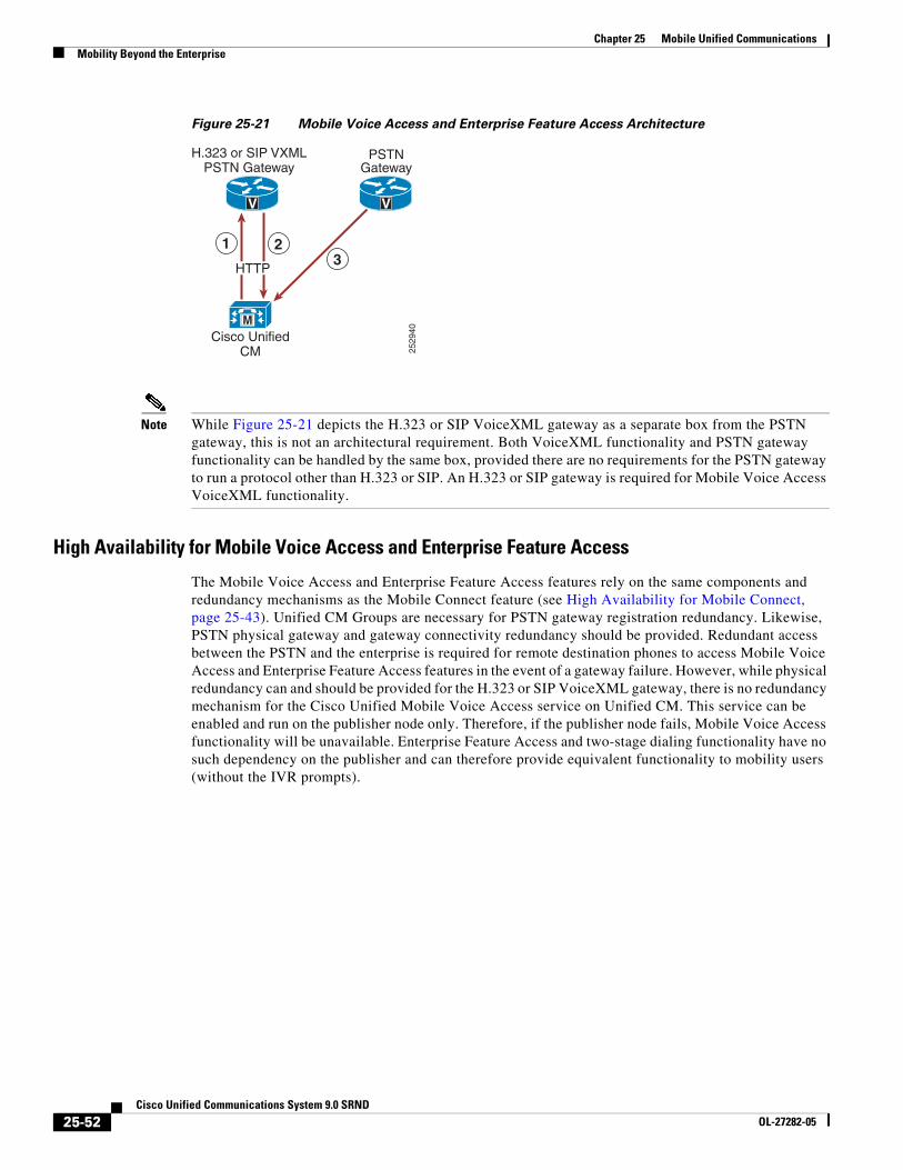
Chapter 25 Mobile Unified CommunicationsMobility Beyond the Enterprise
Figure 25-21 Mobile Voice Access and Enterprise Feature Access Architecture
Note While Figure 25-21 depicts the H.323 or SIP VoiceXML gateway as a separate box from the PSTN gateway, this is not an architectural requirement. Both VoiceXML functionality and PSTN gateway functionality can be handled by the same box, provided there are no requirements for the PSTN gateway to run a protocol other than H.323 or SIP. An H.323 or SIP gateway is required for Mobile Voice Access VoiceXML functionality.
High Availability for Mobile Voice Access and Enterprise Feature Access
The Mobile Voice Access and Enterprise Feature Access features rely on the same components and redundancy mechanisms as the Mobile Connect feature (see High Availability for Mobile Connect, page 25-43). Unified CM Groups are necessary for PSTN gateway registration redundancy. Likewise, PSTN physical gateway and gateway connectivity redundancy should be provided. Redundant access between the PSTN and the enterprise is required for remote destination phones to access Mobile Voice Access and Enterprise Feature Access features in the event of a gateway failure. However, while physical redundancy can and should be provided for the H.323 or SIP VoiceXML gateway, there is no redundancy mechanism for the Cisco Unified Mobile Voice Access service on Unified CM. This service can be enabled and run on the publisher node only. Therefore, if the publisher node fails, Mobile Voice Access functionality will be unavailable. Enterprise Feature Access and two-stage dialing functionality have no such dependency on the publisher and can therefore provide equivalent functionality to mobility users (without the IVR prompts).
2529
40
1 2
H.323 or SIP VXMLPSTN Gateway
PSTNGateway
MCisco Unified
CM
3
V V
HTTP
25-52Cisco Unified Communications System 9.0 SRND
OL-27282-05
Chapter 25 Mobile Unified CommunicationsMobility Beyond the Enterprise
Designing Cisco Unified Mobility DeploymentsThe Cisco Unified Mobility solution delivers mobility functionality via Cisco Unified CM. Functionality includes Mobile Connect, Mobile Voice Access, and Enterprise Feature Access. When deploying this functionality it is important to understand dial plan implications, guidelines and restrictions, and performance and capacity considerations.
Dial Plan Considerations for Cisco Unified Mobility
In order to configure and provision Unified Mobility appropriately, it is important to understand the call routing behavior and dial plan implications of the remote destination profile configuration.
Remote Destination Profile Configuration
When configuring Unified Mobility, you must consider the following two settings on the Remote Destination Profile configuration page:
• Calling Search Space
This setting combines with the directory number or line-level calling search space (CSS) to determine which partitions can be accessed for mobility dialed calls. This affects calls made by the mobility user from the remote destination phone, including Mobile Voice Access and Enterprise Feature Access two-stage dialing as well as calls made in conjunction with mid-call transfer and conferencing features. Ensure that this CSS, in combination with the line-level CSS, contains all partitions that need to be accessed for enterprise calls originating from a user's remote destination phone. In a +E.164 dial plan using the line-only traditional approach with local route groups, this CSS is not required and can be set to <None>.
• Rerouting Calling Search Space
This setting determines which partitions are accessed when calls are sent to a user's remote destination phone. This applies to all Mobile Connect calls. When a call to a user's enterprise directory number is also sent via Mobile Connect to a user's remote destination, this CSS determines how the system reaches the remote destination phone. For this reason, the CSS should provide access to partitions with appropriate route patterns and gateways for reaching the PSTN or mobile voice network.
When configuring the Remote Destination Profile Rerouting CSS, Cisco recommends that the route patterns within this CSS point to a gateway that is in the same call admission control location as the gateway used to route the inbound call to the user's desk phone. This ensures that a call admission control denial due to insufficient bandwidth between two locations will not occur when routing calls out to the remote destination. Further, because subsequent call admission control checks after the initial Mobile Connect call is routed will not result in a denial if there is insufficient WAN bandwidth, routing the inbound and outbound call legs out a gateway or gateways in the same call admission control location ensures that subsequent desk phone or remote destination pickup operations during this call will not require call admission control, which could result in WAN bandwidth oversubscription.
When using route patterns pointing to route lists that use Standard Local Route Group, the local route group configured on the caller’s device pool will be used. In this case the egress gateway for the call leg to the remote destination will be local to the original calling device. For calls coming in from the PSTN, this will help to fulfill the above requirement to use egress gateways in the same call admission control location as the original caller (in this case the incoming gateway).
Likewise, it is equally important to ensure that call admission control denials are minimized when placing two-stage dialed calls. Call admission control denials for two-stage dialed calls can be minimized or avoided by using local route group constructs so that the egress gateway used to route the
25-53Cisco Unified Communications System 9.0 SRND
OL-27282-05
Chapter 25 Mobile Unified CommunicationsMobility Beyond the Enterprise
outbound call leg is chosen by the ingress gateway of the inbound call leg. With this method, the ingress and egress gateways used will be in the same call admission control location. Alternatively, the route patterns within the Remote Destination Profile device-level CCS should point to an egress gateway that is in the same call admission control location as the ingress gateway that handled the inbound call leg to the Mobile Voice Access or Enterprise Feature Access system access number. However, be aware that a subsequent desk phone pickup can result in WAN bandwidth oversubscription if the desk phone is in a different call admission control location than the gateway through which the Mobile Voice Access or Enterprise Feature Access system access numbers are reached.
Automatic Caller ID Matching and Enterprise Call Anchoring
Another aspect of the Unified Mobility dial plan that is important to understand is the system behavior with regard to automatic caller ID identification for inbound calls from configured remote destination phones. Whenever an inbound call comes into the system, the presented caller ID for that call is compared against all configured remote destination phones. If a match is found, the call will automatically be anchored in the enterprise, thus allowing the user to invoke mid-call features and to pick up in-progress calls at their desk phone. This behavior occurs for all inbound calls from any mobility user's remote destination phone, even if the inbound call is not originated as a mobility call using Mobile Voice Access or Enterprise Feature Access.
Note Automatic inbound caller ID matching for configured remote destination numbers is affected by whether the Matching Caller ID with Remote Destination service parameter is set to Partial or Complete Match. See Remote Destination Configuration and Caller ID Matching, page 25-50, for more information about this setting.
In addition to automatic enterprise call anchoring, inbound and outbound call routing must also be considered when a configured remote destination phone is calling into the enterprise. Inbound call routing for calls from configured remote destinations occurs in one of two ways, depending on the setting of the service parameter Inbound Calling Search Space for Remote Destination. By default, this service parameter is set to Trunk or Gateway Inbound Calling Search Space. With the service parameter set to the default value, inbound calls from configured remote destinations will be routed using the Inbound Calling Search Space (CSS) of the PSTN gateway or trunk on which the call is coming in. If, on the other hand, the parameter Inbound Calling Search Space for Remote Destination is set to the value Remote Destination Profile + Line Calling Search Space, inbound calls coming from remote destinations will bypass the Inbound CSS of the PSTN gateway or trunk and will instead be routed using the associated Remote Destination Profile CSS (in combination with the line-level CSS).
Given the nature of inbound call routing from remote destination phones, it is important to make sure that calling search spaces are configured appropriately in order to provide access for these inbound calls to any partitions required for reaching internal enterprise phones, thus ensuring proper call routing from remote destination phones.
Note Incoming calls that do not come from a configured remote destination phone are not affected by the Inbound Calling Search Space for Remote Destination service parameter because they will always use the trunk or gateway inbound CSS.
Outbound call routing for Mobile Voice Access or Enterprise Feature Access calls always uses a concatenation of the Remote Destination Profile line CSS and device-level CSS, therefore it is important to make sure that these calling search spaces are configured appropriately in order to provide access to any route patterns necessary for off-net or PSTN access, thus ensuring proper outbound call routing from remote destination phones.
25-54Cisco Unified Communications System 9.0 SRND
OL-27282-05
Chapter 25 Mobile Unified CommunicationsMobility Beyond the Enterprise
Intelligent Session Control and Ring All Shared Lines
The Intelligent Session Control feature enables automatic call anchoring for enterprise-originated calls made directly to configured remote destination numbers. Normally, mobility call anchoring is dependent exclusively on calls made to or on behalf of a user's enterprise number. The system already anchors externally originated calls made by enterprise two-stage dialing because these call are routed as internal calls. With the Intelligent Session Control feature enabled, the system will also anchor internally originated calls made directly to configured remote destinations.
This feature is enabled by setting the Reroute Remote Destination Calls to Enterprise Number service parameter to True. By default, this service parameter is set to False and the feature is disabled. When the feature is enabled, not only will the system route the call to the dialed remote destination by way of the PSTN, but it will also automatically anchor the call inside the enterprise gateway. By anchoring these types of calls, the system enables the called mobile user to invoke mid-call features and desk phone pickup or session handoff.
As an example, assume that the Intelligent Session Control feature has been enabled and that a mobility-enabled user has a remote destination number configured as 408 555 1234, which corresponds to their mobile number. If another system user dials the mobility-enabled user's remote destination number (408 555 1234) from their desk phone, the system will route the call through the PSTN to the remote destination and will simultaneously anchor the call in the enterprise gateway. Once the call is set up and anchored, the called mobility-enabled user now has the ability to invoke mid-call features such as hold, transfer, and conference, as well as the ability to perform a desk phone pickup or session handoff.
Taking this same example and assuming instead that the Intelligent Session Control feature is disabled, then when a system user dials the mobility-enabled user’s remote destination directly from a desk phone inside the enterprise, the call will still be routed to the called remote destination through the PSTN; however, the call will not be anchored. As a result, the mobile user would not be able to invoke mid-call hold or transfer and would have no ability to perform a desk phone pickup or session handoff.
When enabling this feature, it is important to understand the implications to dial plan configuration and call routing. To invoke the feature, the number dialed by an internal user to reach a remote destination number on the PSTN (including any required PSTN steering digits) must match the remote destination (or mobility identity) number as it is configured on the system. For example, if the remote destination number is configured on the system as 408 555 1234 but internal users must normally dial PSTN steering digits 91 in addition to the number they are calling, then rerouting and resulting enterprise call anchoring will not occur. This is because the user dialed 91 408 555 1234 to reach the remote destination on the PSTN but the remote destination was configured as 408 555 1234, so there is no match.
For this feature to function properly, matching must occur between the configured remote destination and the number that must be dialed to reach this remote destination on the PSTN. To ensure that this matching happens, set the service parameter Matching Caller ID with Remote Destination to Partial Match. By setting this parameter to Partial Match and then specifying the number of digits to partially match using the Number of Digits for Caller ID Partial Match service parameter, it is still possible to match the configured remote destination number with the dialed number even if it contains PSTN steering digits.
Using the previous example and assuming that system has been set to use partial match on ten digits, the dialed number 9 1 408 555 1234 can be matched to the configured remote destination 408 555 1234. This is because, with partial matching, the system attempts to match the same number of digits as specified by the Number of Digits for Caller ID Partial Match, which in this case is ten digits. The system attempts to match the two numbers by matching digits from right to left. The last ten digits of the dialed number 9 1 408 555 1234 are 408 555 1234, and these ten digits match the ten digits of the configured remote destination (408 555 1234). In this example, the resulting call is anchored in the enterprise and the called mobile user is able to invoke mid-call features and perform desk phone pickup or session handoff.
25-55Cisco Unified Communications System 9.0 SRND
OL-27282-05
Chapter 25 Mobile Unified CommunicationsMobility Beyond the Enterprise
At first glance it might appear that an easier way to handle this feature would be to configure remote destination or mobility identity numbers that include any required PSTN steering digits. However, when configuring these numbers with required PSTN steering digits, if you do not also configure partial caller ID matching, the system will not be able to perform automatic caller ID matching and enterprise anchoring for inbound calls from configured remote destinations or mobility identities. In the previous example, if the remote destination number had been configured as 9 1 408 555 1234 and complete caller ID matching had been used, an inbound call from the remote destination would present caller ID of 408 555 1234 and a match would not occur, meaning the inbound call from the remote destination would not be anchored as expected.
Based on this potential for mismatch between dialed numbers for outbound calls and configured remote destination numbers for inbound calls, Cisco recommends enabling partial (rather than complete) caller ID matching when using the Intelligent Session Control feature for all deployments that require one or more steering digits to reach the PSTN. This ensures that calls made directly to the remote destination number using PSTN steering digits are still matched and anchored. On the other hand, if steering digits are not required to reach the PSTN and users are able to dial the full E.164 number to route calls to the PSTN, then Cisco recommends the complete caller ID matching setting because the remote destination is configured to match the caller ID and is the same number as dialed by internal users to reach the remote destination or mobility identity on the PSTN.
When enabling the Intelligent Session Control feature, it is also important to understand the behavior of the enterprise and remote destination lines during the reroute feature operation. On call reroute, remote destination line settings Do Not Disturb (DND), Access Lists and Time of Day call filtering, and the Delay Before Ringing Timer are ignored. All reroute calls are routed unfiltered and immediately. Enterprise desk phone line settings are also ignored or bypassed by default. However, Call Forward All settings on the enterprise desk phone line can be honored during reroute feature operation by setting the Ignore Call Forward All on Enterprise DN service parameter to False. If this parameter is set to False, on reroute operation, calls will not be routed to the remote destination if the enterprise desk phone line has a call-forward-all destination set. Instead, the call will be routed to the call-forward-all destination. By default, this service parameter is set to True, and call-forward-all settings on enterprise desk phone lines are ignored.
Intelligent Session Control functionality may be further enhanced by using the Ring All Shared Lines feature. This feature is enabled by setting the Ring All Shared Lines service parameter to True. By default, this service parameter is set to True and the feature is enabled. However, the Ring All Shared Lines feature is dependent on the Intelligent Session Control feature, which must also be enabled in order use the Ring All Shared Line functionality. When the Ring All Shared Lines and Intelligent Session Control features are both enabled, not only will the system route internally originated calls to the dialed remote destination by way of the PSTN, but all of the user's other shared-line devices will also receive the call. This includes the user's enterprise desk phone as well as other configured remote destinations. The called user will then be able to answer the incoming call on any of their devices and the call will be anchored in the enterprise.
Note If Ring All Shared Lines is enabled, mobile client devices will not receive calls at the cellular voice interface of the device when the device is registered to Unified CM.
25-56Cisco Unified Communications System 9.0 SRND
OL-27282-05
Chapter 25 Mobile Unified CommunicationsMobility Beyond the Enterprise
Caller ID Transformations
Any calls made into the cluster by configured remote destination numbers will automatically have their caller ID or calling number changed from the calling remote destination phone number to the enterprise directory number of the associated desk phone. For example, if a remote destination phone with number 408 555-7890 has been configured and associated to a user's enterprise desk phone with number 555-1234, then any call from the user's remote destination phone destined for any directory number in the cluster will automatically have the caller ID changed from the remote destination number of 408 555-7890 to the enterprise directory number of 555-1234. This ensures that the active call caller ID display and call history log caller ID reflect a mobility user's enterprise desk phone number rather than their mobile phone number, and it ensures that any return calls are made to the user's enterprise number, thus anchoring those calls within the enterprise.
Likewise, calls from a remote destination phone to external PSTN destinations and anchored in the enterprise via Mobile Voice Access or Enterprise Feature Access two-stage dialing, or those calls forked to the PSTN as a result of Mobile Connect, will also have caller ID changed from the calling remote destination phone number to the associated enterprise directory number.
Finally, in order to deliver the calling party number as an enterprise DID number rather than an enterprise directory number to external PSTN phones, calling party transformation patterns can be used. By using calling party transformation patterns to transform caller IDs from enterprise directory numbers to enterprise DIDs, return calls from external destinations will be anchored within the enterprise because they will be dialed using the full enterprise DID number. For more information about these transformations and dial plan implications, see Special Considerations for Cisco Unified Mobility, page 9-125.
Guidelines and Restrictions for Unified Mobility
The following guidelines and restrictions apply with regard to deployment and operation of Mobile Connect within the Unified CM telephony environment:
• Mobile Connect is supported only with PRI TDM PSTN connections. T1 or E1-CAS, FXO, FXS, and BRI PSTN connections are not supported. This PRI requirement is based on the fact that Cisco Unified CM must receive expeditious answer and disconnect indication from the PSTN in order to ensure full feature support. Answer indication is needed in order for Cisco Unified CM to stop ringing the desk phone and other remote destinations when a Mobile Connect call is answered at a particular remote destination. In addition, answer indication is required in order to support the single enterprise voicemail box feature. Finally, disconnect indication is required for desk phone pickup. A PRI PSTN connection will always provide answer or disconnect indication.
• Mobile Connect is also supported over SIP trunk VoIP PSTN connections as long as the Cisco IOS Unified Border Element provides the demarcation point between the Unified CM SIP trunk and the service provider trunk and as long as mid-call features (or other DTMF-dependent features) are not in use. Mid-call features are not supported over VoIP PSTN connections. A VoIP-based PSTN connection is still able to provide expeditious answer and disconnect indication to Unified CM due to the end-to-end signaling path provided by VoIP-based PSTN connections.
• Mobile Connect can support up to two simultaneous calls per user. Any additional calls that come in are automatically transferred to the user’s voicemail.
• Mobile Connect does not work with Multilevel Precedence and Preemption (MLPP). If a call is preempted with MLPP, Mobile Connect features are disabled for that call.
• Mobile Connect services do not extend to video calls. A video call received at the desktop phone cannot be picked up on the cellular phone.
25-57Cisco Unified Communications System 9.0 SRND
OL-27282-05
Chapter 25 Mobile Unified CommunicationsMobility Beyond the Enterprise
• The Unified CM Forced Authorization Code and Client Matter Code (FAC/CMC) feature does not work with Mobile Voice Access or Enterprise Feature Access.
• Remote destinations must be Time Division Multiplex (TDM) devices or off-system IP phones on other clusters or systems. You cannot configure IP phones within the same Unified CM cluster as remote destinations.
For additional guidelines and restrictions, refer to the information on Cisco Unified Mobility in the latest version of the Cisco Unified Communications Manager Features and Services Guide, available at
http://www.cisco.com/en/US/products/sw/voicesw/ps556/prod_maintenance_guides_list.html
Capacity Planning for Cisco Unified Mobility
Cisco Unified Mobility supports a maximum of 15,000 remote destinations or mobility identities per Unified CM cluster. The maximum number of mobility-enabled users would thus be 15,000 users, assuming a single remote destination or mobility identity per user. As the number of remote destinations or mobility identities per user increases, the number of supported mobility-enabled users decreases.
Note A mobility-enabled user is defined as a user that has a remote destination profile and at least one remote destination or a mobility identity configured.
Note A mobility identity is configured just like a remote destination within the system, and it has the same capacity implications as a remote destination. Unlike a remote destination, however, the mobility identity is associated directly to a phone device rather than a remote destination profile. The mobility identity applies only to mobile client devices such as Cisco Jabber.
Scalability and performance of Cisco Unified Mobility ultimately depends on the number of mobility users, the number of remote destinations or mobility identities each user has, and the busy hour call attempt (BHCA) rates of those users. Multiple remote destinations per user and/or high BHCA per user can result in lower capacity for Cisco Unified Mobility. For more information on Cisco Unified Mobility sizing, including Unified CM server node capacities and hardware specific per-node and per-cluster capacities, see the chapter on Unified Communications Design and Deployment Sizing Considerations, page 29-1.
Design Considerations for Cisco Unified Mobility
Observe the following design recommendations when deploying Unified Mobility:
• Ensure that the PSTN gateway protocol is capable of out-of-band DTMF relay or allocate media termination points (MTPs) in order to covert in-band DTMF to out-of-band DTMF. When using Cisco IOS gateways for PSTN connectivity, out-of-band DTMF relay will be supported. However, third-party gateways might not support a common out-of-band DTMF method, and as a result an MTP might be required. In order to use Enterprise Feature Access Two-Stage Dialing and mid-call features, DTMF digits must be received out-of-band by Cisco Unified CM.
Note When relying on MTP for converting in-band DTMF to out-of-band DTMF, be sure to provide sufficient MTP capacity. If heavy or frequent use of Enterprise Feature Access Two-Stage Dialing or mid-call features is anticipated, Cisco recommends a hardware-based MTP or Cisco IOS software-based MTP.
25-58Cisco Unified Communications System 9.0 SRND
OL-27282-05
Chapter 25 Mobile Unified CommunicationsMobility Beyond the Enterprise
• Prior to deploying Unified Mobility, it is important to work with the PSTN provider to ensure the following:
– Caller ID is provided by the service provider for all inbound calls to the enterprise. This is a requirement if Enterprise Feature Access Two-Stage Dialing or mid-call transfer, conference, and directed call park features are needed.
– Outbound caller ID is not restricted by the service provider. This is a requirement if there is an expectation that mobility-enabled users will receive the caller ID of the original caller at their remote destination rather than a general enterprise system number or other non-meaningful caller ID.
Note Some providers restrict outbound caller ID on a trunk to only those DIDs handled by that trunk. For this reason, a second PRI trunk that does not restrict caller ID might have to be acquired from the provider. To obtain an unrestricted PRI trunk, some providers might require a signed agreement from the customer indicating they will not send or make calls to emergency numbers over this trunk.
Note Some providers allow unrestricted outbound caller ID on a trunk as long as the Redirected Dialed Number Identification Service (RDNIS) field or SIP Diversion Header contains a DID handled by the trunk. The RDNIS or SIP Diversion Header for forked calls to remote destinations can be populated with the enterprise number of the user by checking the Redirecting Number IE Delivery - Outbound check box on the gateway or trunk configuration page. Contact your service provider to determine if they honor the RDNIS or SIP Diversion Header and allow unrestricted outbound caller ID.
• Because mobility call flows typically involve multiple PSTN call legs, planning and allocation of PSTN gateway resources is extremely important for Unified Mobility. In cases where there are large numbers of mobility-enabled users, PSTN gateway resources will have to be increased. The following methods are recommend to minimize or reduce PSTN utilization:
– Limit the number of remote destinations per mobility-enabled user to one (1). This will reduce the number of DS0s that are needed to extend the inbound call to the user's remote destination. One DS0 is consumed for each configured remote destination when a call comes into the user's enterprise directory number, even if the call is not answered at one of the remote destinations. Note that a DS0 per remote destination may be used for as long as 10 seconds, even if the call is not answered at the remote destination.
– Use access lists to block or restrict the extension of calls to a particular remote destination based on incoming caller ID. Because access lists can be invoked based on the time of day, this eliminates the need for repeated updates of access lists by the end-user or the administrator.
– Educate end-users to disable Mobile Connect when not needed, to further eliminate DS0 utilization when a call comes in for that user's enterprise number. If Mobile Connect is disabled, incoming calls will still ring the desk phone and will still forward to enterprise voicemail if the call goes unanswered.
• Due to the potential for call admission control denials resulting from insufficient WAN bandwidth between locations and the possibility that a desk phone pickup or remote destination pickup may result in a WAN bandwidth oversubscription, Cisco recommends configuring Remote Destination Profile CSS and Rerouting CSS so that route patterns within these CSSs point to gateways that are located within the same call admission control location as the gateway on which the inbound call leg comes in. For more information, see Remote Destination Profile Configuration, page 25-53.
25-59Cisco Unified Communications System 9.0 SRND
OL-27282-05
Chapter 25 Mobile Unified CommunicationsMobility Beyond the Enterprise
• If you enable the Intelligent Session Control feature in deployments where PSTN steering digits must be dialed to access the PSTN, Cisco recommends setting the Matching Caller ID with Remote Destination service parameter to Partial Match and configuring the appropriate number of digits (Number of Digits for Caller ID Partial Match service parameter) to achieve a partial match of configured remote destinations or mobility identities. This will ensure proper functioning of the Intelligent Session Control feature and the mobility automatic caller ID matching and anchoring features.
Cisco Mobile Clients and DevicesAs the prevalence of mobile users, mobile phones, and mobile carrier services continues to increase, the ability to use a single device for voice, video, and data services both inside and outside the enterprise becomes increasingly attractive. Mobile devices, including dual-mode smartphones and the clients that run on them, afford an enterprise the ability to provide customized voice, video, and data services to users while inside the enterprise and to leverage the mobile carrier network as an alternate connection method for general voice and data services. By enabling voice, video, and data services inside the enterprise and providing network connectivity for mobile client devices, enterprises are able to provide these services locally at reduced connectivity costs. For example, voice over IP (VoIP) calls made on the enterprise network will typically incur less cost than those same calls made over the mobile voice network.
In addition to providing voice and video over IP (VVoIP) capabilities, these mobile clients and devices enable mobile users to access and leverage other back-end collaboration applications and services. Other services and applications that can be leveraged through Cisco mobile clients and services include enterprise directory, enterprise voicemail, and XMPP-based enterprise IM (instant messaging) and presence. Further, these clients and devices can be deployed in conjunction with Cisco Unified Mobility so that users can leverage additional features and functions with their mobile device, such as Mobile Connect, enterprise two-stage dialing through Mobile Voice Access or Enterprise Feature Access, and single enterprise voicemail box.
This section examines mobile client architecture and common functions and features provided by Cisco mobile clients and devices, including remote secure attachment and handoff considerations related to moving an active voice call between the enterprise WLAN network and the mobile voice network. After covering the general mobile client solution architecture and features and functions, this section provides coverage of various capabilities and integration considerations for the following specific mobile clients and devices:
• Cisco Jabber — A set of mobile clients for Android and iOS mobile devices including iPhone and iPad, providing the ability to make voice and/or video calls over IP on the enterprise WLAN network or over the mobile data network as well as the ability to access the corporate directory and enterprise voicemail services and XMPP-based enterprise IM and presence.
• Cisco Cius — A purpose-built Android-based enterprise tablet device providing the ability to make voice and video calls over WLAN or mobile data networks and to access additional enterprise services such as directory, voicemail, IM and presence.
In addition, this section discusses high availability and capacity planning considerations for Cisco mobile clients and devices.
25-60Cisco Unified Communications System 9.0 SRND
OL-27282-05
Chapter 25 Mobile Unified CommunicationsMobility Beyond the Enterprise
Cisco Mobile Clients and Devices Architecture
Cisco mobile clients are deployed on a wide range of mobile devices including tablets and handheld devices with only IP-based network connectivity capabilities (IEEE 802.11 wireless local area network or mobile provider data network) and dual-mode phones, which contain two physical interfaces or radios that enable the device to connect to both mobile voice and data carrier networks by means of traditional cellular or mobile network technologies and to connect to wireless local area networks (WLANs) using 802.11. Cisco mobile clients and devices enable on-premises data and real-time traffic (voice and video) connectivity through an 802.11 WLAN. In addition, these clients and devices provide remote data and real-time traffic (voice and video) connectivity to the enterprise through public or private WLANs or over the mobile data network. For devices with provider cellular voice radios, voice connectivity may also be enabled through the mobile voice network and PSTN.
Note The use of the term dual-mode phone in this section refers specifically to devices with 802.11 radios in addition to the cellular radio for carrier voice and data network connectivity. Dual-mode devices that provide Digital Enhanced Cordless Telecommunications (DECT) or other wireless radios and/or multiple cellular radios are outside the scope of this section.
Figure 25-22 depicts the basic Cisco mobile clients and devices solution architecture for connecting mobile client devices into a Cisco Unified Communications System. For voice and video services, mobile client devices associate to the enterprise WLAN or connect over the Internet (from a public or private WLAN hot spot or the mobile data network), and the Cisco mobile client registers to Cisco Unified CM as an enterprise phone using the Session Initiation Protocol (SIP). Alternatively, some mobile clients may instead register to Cisco Video Communications System (VCS) as a video endpoint using SIP. Once registered, the client device relies on the underlying enterprise Cisco IP telephony network for making and receiving calls. When the mobile device is connected to the enterprise network and the client is registered to Unified CM, the device is reachable through the user's enterprise number. Any inbound calls to the user's enterprise number will ring the mobile client device. If the user has a Cisco IP desk phone, then the mobile client registration enables a shared line instance for the user's enterprise number so that an incoming call rings both the user's desk phone and the mobile device. When unregistered, the mobile client device will not receive incoming enterprise calls unless the mobile device has an active cellular voice radio, the user has been enabled for Cisco Unified Mobility, and Mobile Connect (or single number reach) has been turned on for the user's mobile phone number. In these scenarios the mobile voice network and PSTN are used for making and receiving voice-only calls.
Unified Mobility features such as Mobile Connect are not compatible with tablets and other mobile client devices that do not have cellular voice radios because these non-dual-mode devices do not have a native PSTN reachable number. Non-dual-mode devices are able to make and receive enterprise calls only when connected to the enterprise and registered to the enterprise call control system.
As shown in Figure 25-22, when attached to the enterprise, Cisco mobile clients and devices can also communicate directly with other back-end application servers such as the LDAP corporate directory, Cisco Unity Connection enterprise voicemail system, and the Cisco IM and Presence Service for access to additional enterprise unified communications services such as messaging and presence. Cisco mobile clients and devices also integrate with cloud-based collaboration services such as Cisco WebEx, which delivers IM and presence, point-to-point IP calling, and web conferencing services.
25-61Cisco Unified Communications System 9.0 SRND
OL-27282-05
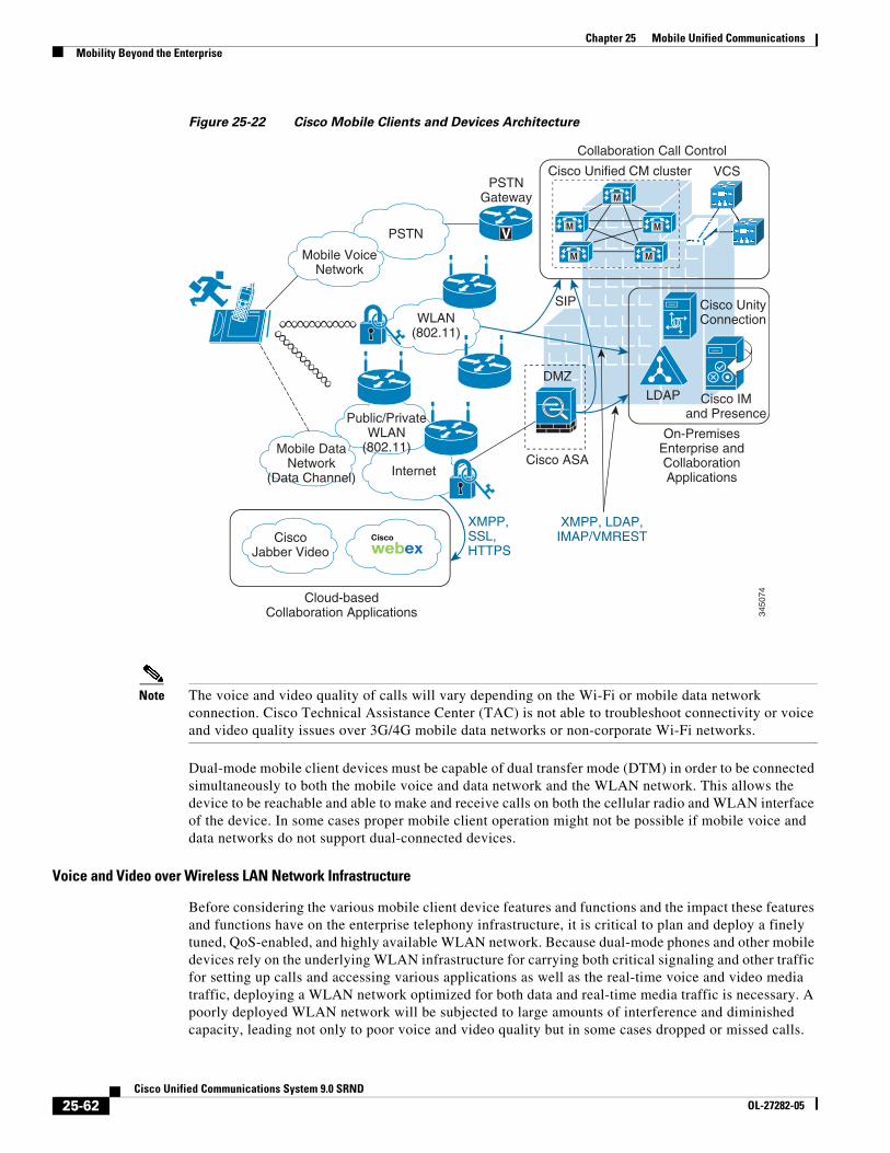
Chapter 25 Mobile Unified CommunicationsMobility Beyond the Enterprise
Figure 25-22 Cisco Mobile Clients and Devices Architecture
Note The voice and video quality of calls will vary depending on the Wi-Fi or mobile data network connection. Cisco Technical Assistance Center (TAC) is not able to troubleshoot connectivity or voice and video quality issues over 3G/4G mobile data networks or non-corporate Wi-Fi networks.
Dual-mode mobile client devices must be capable of dual transfer mode (DTM) in order to be connected simultaneously to both the mobile voice and data network and the WLAN network. This allows the device to be reachable and able to make and receive calls on both the cellular radio and WLAN interface of the device. In some cases proper mobile client operation might not be possible if mobile voice and data networks do not support dual-connected devices.
Voice and Video over Wireless LAN Network Infrastructure
Before considering the various mobile client device features and functions and the impact these features and functions have on the enterprise telephony infrastructure, it is critical to plan and deploy a finely tuned, QoS-enabled, and highly available WLAN network. Because dual-mode phones and other mobile devices rely on the underlying WLAN infrastructure for carrying both critical signaling and other traffic for setting up calls and accessing various applications as well as the real-time voice and video media traffic, deploying a WLAN network optimized for both data and real-time media traffic is necessary. A poorly deployed WLAN network will be subjected to large amounts of interference and diminished capacity, leading not only to poor voice and video quality but in some cases dropped or missed calls.
Internet
XMPP,SSL,HTTPS
SIP
PSTNGateway
WLAN(802.11)
Public/PrivateWLAN
(802.11)Mobile DataNetwork
(Data Channel)
CiscoJabber Video
Cisco
webex
VPSTN
Mobile VoiceNetwork
Cisco Unified CM cluster VCS
Cisco UnityConnection
LDAPDMZ
Cisco ASA
XMPP, LDAP,IMAP/VMREST
Cisco IMand Presence
Collaboration Call Control
On-PremisesEnterprise andCollaborationApplications
Cloud-basedCollaboration Applications
M
M
M M
M
3450
74
25-62Cisco Unified Communications System 9.0 SRND
OL-27282-05
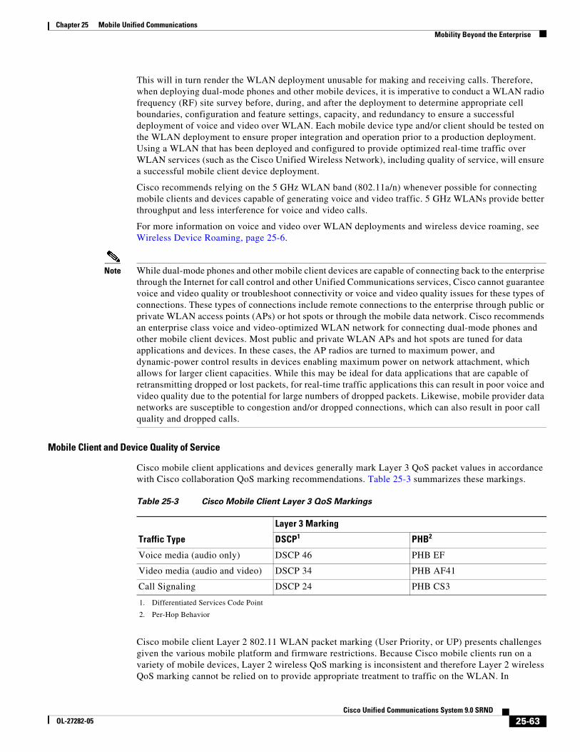
Chapter 25 Mobile Unified CommunicationsMobility Beyond the Enterprise
This will in turn render the WLAN deployment unusable for making and receiving calls. Therefore, when deploying dual-mode phones and other mobile devices, it is imperative to conduct a WLAN radio frequency (RF) site survey before, during, and after the deployment to determine appropriate cell boundaries, configuration and feature settings, capacity, and redundancy to ensure a successful deployment of voice and video over WLAN. Each mobile device type and/or client should be tested on the WLAN deployment to ensure proper integration and operation prior to a production deployment. Using a WLAN that has been deployed and configured to provide optimized real-time traffic over WLAN services (such as the Cisco Unified Wireless Network), including quality of service, will ensure a successful mobile client device deployment.
Cisco recommends relying on the 5 GHz WLAN band (802.11a/n) whenever possible for connecting mobile clients and devices capable of generating voice and video traffic. 5 GHz WLANs provide better throughput and less interference for voice and video calls.
For more information on voice and video over WLAN deployments and wireless device roaming, see Wireless Device Roaming, page 25-6.
Note While dual-mode phones and other mobile client devices are capable of connecting back to the enterprise through the Internet for call control and other Unified Communications services, Cisco cannot guarantee voice and video quality or troubleshoot connectivity or voice and video quality issues for these types of connections. These types of connections include remote connections to the enterprise through public or private WLAN access points (APs) or hot spots or through the mobile data network. Cisco recommends an enterprise class voice and video-optimized WLAN network for connecting dual-mode phones and other mobile client devices. Most public and private WLAN APs and hot spots are tuned for data applications and devices. In these cases, the AP radios are turned to maximum power, and dynamic-power control results in devices enabling maximum power on network attachment, which allows for larger client capacities. While this may be ideal for data applications that are capable of retransmitting dropped or lost packets, for real-time traffic applications this can result in poor voice and video quality due to the potential for large numbers of dropped packets. Likewise, mobile provider data networks are susceptible to congestion and/or dropped connections, which can also result in poor call quality and dropped calls.
Mobile Client and Device Quality of Service
Cisco mobile client applications and devices generally mark Layer 3 QoS packet values in accordance with Cisco collaboration QoS marking recommendations. Table 25-3 summarizes these markings.
Cisco mobile client Layer 2 802.11 WLAN packet marking (User Priority, or UP) presents challenges given the various mobile platform and firmware restrictions. Because Cisco mobile clients run on a variety of mobile devices, Layer 2 wireless QoS marking is inconsistent and therefore Layer 2 wireless QoS marking cannot be relied on to provide appropriate treatment to traffic on the WLAN. In
Table 25-3 Cisco Mobile Client Layer 3 QoS Markings
Traffic Type
Layer 3 Marking
DSCP1
1. Differentiated Services Code Point
PHB2
2. Per-Hop Behavior
Voice media (audio only) DSCP 46 PHB EF
Video media (audio and video) DSCP 34 PHB AF41
Call Signaling DSCP 24 PHB CS3
25-63Cisco Unified Communications System 9.0 SRND
OL-27282-05
Chapter 25 Mobile Unified CommunicationsMobility Beyond the Enterprise
deployments with Cisco Unified Wireless LAN Controllers, enabling wireless SIP call admission control (CAC) might provide some relief for incorrect or nonexistent Layer 2 WLAN marking. SIP CAC utilizes media session snooping and ensures that downstream voice and video frames are prioritized and/or treated correctly.
Despite appropriate mobile client application Layer 3 or even Layer 2 packet marking, mobile devices present many of the same challenges as desktop PCs in terms of generating many different types of traffic, including both data and real-time traffic. Given this, mobile devices generally fall into the untrusted category of collaboration endpoints. For deployments where mobile client devices are not considered trusted endpoints, packet marking or re-marking based on traffic type and port numbers is required to ensure that network priority queuing and dedicated bandwidth is applied to appropriate traffic. In addition to re-marking the mobile device traffic, Cisco recommends using network-based policing and rate limiting to ensure that the mobile client devices do not consume too much network bandwidth.
Alternatively, given appropriate Cisco mobile client Layer 3 marking and assuming mobile client devices are trusted, Cisco mobile client traffic will be queued appropriately as it traverses the enterprise network by using priority voice queuing and dedicated video media and call signaling bandwidth queues.
Cisco Mobile Clients and Devices Features and Functions
Cisco mobile clients and devices provide a range of features and functions. While features and operations may vary from device to device, the common operations and behaviors described in this section apply to all Cisco mobile client devices.
Enterprise Call Routing
Because Cisco mobile clients and devices are capable of making and receiving calls using the enterprise telephony infrastructure and call control services, it is important to understand the nature and behavior of call routing as it pertains to mobile client devices.
Inbound Call Routing
When mobile clients and devices register to Unified CM as an enterprise device with enterprise number, the mobile device rings when incoming calls to the system are destined for the user's enterprise number. This occurs for incoming calls originated on the PSTN or from other Unified CM clusters or enterprise IP telephony systems as well as for incoming calls originated within the Unified CM cluster by other users. If the mobile client device user has other devices or clients that are also associated to the enterprise number, these devices will also ring as shared lines; and once the call is answered at one of the devices or clients, ringing of all other devices and clients ceases.
In scenarios where a user has been enabled for Cisco Unified Mobility, and when Mobile Connect or single number reach is enabled for the user's dual-mode mobile phone number, the incoming call may also be extended to the mobility identity corresponding to the user's mobile phone number. However, this depends on whether the mobile device is connected to the enterprise WLAN network or attached to the enterprise network through secure VPN and registered to Unified CM. In situations in which the device is connected to the enterprise network directly or through a secure remote connection, an incoming call to the user's enterprise number will not be extended by Mobile Connect to the mobility identity of the mobile device even if Mobile Connect is turned on for this mobile number. The reason an incoming call to the enterprise number is not extended to the mobility identity of a dual-mode mobile device when it is registered to Unified CM is that the system is aware the device is connected to the enterprise network and available. Thus, in order to reduce utilization of enterprise PSTN resources, Unified CM does not extend the call to the dual-mode mobile phone's mobile voice network interface through the PSTN. Instead, only the WLAN or mobile data network interface corresponding to the enterprise number receives the call.
25-64Cisco Unified Communications System 9.0 SRND
OL-27282-05
Chapter 25 Mobile Unified CommunicationsMobility Beyond the Enterprise
For situations in which the mobile device is not connected to the enterprise network directly or through a secure remote connection or is not registered to Unified CM, incoming calls to the enterprise number will be extended to the dual-mode mobile phone number per the configured mobility identity, assuming that the user has been enabled for Unified Mobility and that Mobile Connect for the mobility identity is turned on. For more information on integration of mobile clients and devices with Unified Mobility, see Interactions Between Cisco Jabber and Cisco Unified Mobility, page 25-75.
The same behavior and logic described above also applies with the Ring All Shared Lines feature. If this feature is enabled, calls are extended to the mobility identity or cellular number only when the dual-mode mobile client device is not registered to Unified CM. For more information on the Ring All Share Line feature, see Intelligent Session Control and Ring All Shared Lines, page 25-55.
In all cases, incoming calls made directly to the dual-mode device's mobile network phone number will always be routed directly to the mobile voice interface of the dual-mode device on the mobile network, unless the provider network or device settings are such that calls are not extended to the device by the mobile network. This is considered appropriate behavior because these calls were not made to the user's enterprise number. These would be considered personal calls, and as such should not be routed through the enterprise.
Note Mobile client devices that do not have cellular voice radios, such as the Cisco Cius and other tablet devices, are not dual-mode devices and as such cannot be reached on a mobile voice network interface. These devices can be reached only at the enterprise number by voice-over-IP.
Outbound Call Routing
For outbound calls from the dual-mode mobile device, the interface used depends on the location and connectivity of the device at that particular time. If the dual-mode device is not connected to the enterprise and not registered to Unified CM, then calls are routed by the cellular voice radio interface to the mobile voice network as usual. However, when connected to the enterprise and registered to Unified CM, the mobile device should make all calls through the enterprise telephony infrastructure. If no enterprise connectivity is available or the mobile client is unregistered, then outbound calling is not possible from the enterprise number, and instead calls would have to use the mobile number of the mobile client device for making calls over the mobile voice network. Alternatively, users may use the two-stage dialing features provided with Cisco Unified Mobility (see Mobile Voice Access and Enterprise Feature Access, page 25-44).
Dial Plan
The enterprise dial plan determines the dialing behavior of the mobile client device when it is connected to the enterprise and registered to Unified CM. For example, if the enterprise dial plan is configured to allow abbreviated dialing to reach internal extensions, then a mobile device registered to Unified CM can use this abbreviated dialing. While it is certainly a convenience for dual-mode mobile phone users to be able to dial within the enterprise using enterprise dialing habits and abbreviated dialing as well as site-based and/or PSTN steering digits for outbound calls, it is also a somewhat unnatural dialing scheme because mobile phone users typically dial numbers for outgoing calls on their mobile phone by using full E.164 dial strings since this is what is expected by the mobile voice network for outbound calling.
The enterprise dialing experience for an end-user is ultimately up to the enterprise policies and administrator of the enterprise telephony deployment. However, for dual-mode mobile devices, Cisco recommends normalizing required dialing strings for dual-mode client devices so that user dialing habits are maintained whether the device is connected to the enterprise network and registered to Unified CM or not. Because dialing on the mobile voice network is typically done using full +E.164 (with a preceding '+') and mobile phone contacts are typically stored with full +E.164 numbers, Cisco recommends configuring the enterprise dial plan to accommodate full +E.164 with preceding '+' for dual-mode mobile devices. When the dial plan is configured within Unified CM to handle this type of
25-65Cisco Unified Communications System 9.0 SRND
OL-27282-05
Chapter 25 Mobile Unified CommunicationsMobility Beyond the Enterprise
outbound dialing for dual-mode phones, it is possible for users to store a single set of contacts on the phone in the +E.164 format and, when dialed from these contacts or manually using the full +E.164 number, calls will always be routed to the appropriate destination, whether the device is connected to the enterprise network directly or over secure remote connection and registered to Unified CM or connected only to the mobile voice network. Configuring the enterprise dial plan in this manner provides the best possible end-user dialing experience so that users' mobile device dialing habits are maintained and they do not have to be aware of whether the device has enterprise connectivity and is registered to Unified CM.
To achieve normalized dialing from dual-mode phones, whether connected to the enterprise or just the mobile voice network, configure the dial plan within Unified CM with the following considerations in mind:
• Ensure that the enterprise dial plan is capable of handling dial strings from dual-mode phones typically used on the mobile voice network. For example, the dial plan should be configured to handle the following strings, which might be dialed from a mobile phone to reach a particular phone through the mobile voice network: +1 408 555 1234, 408 555 1234. Supporting the latter 10-digit dialing method (for example, 408 555 1234) might potentially overlap with other dialing habits such as abbreviated intra-site dialing. In that case the administrator has to decide which of the colliding dialing habits (10-digit dialing or abbreviated intra-site) should be available for dual-mode phones registered to the enterprise network. The set of dialing habits supported on dual-mode phones often differs from the set of dialing habits supported on regular endpoints.
• For calls destined for other enterprise numbers, systems configured for abbreviated dialing should be capable of modifying dial strings and rerouting to enterprise extensions as appropriate. For example, assuming the enterprise dial plan is based on five-digit internal dialing, the system should be configured to handle call routing to an enterprise extension so that a call to made to +1 408 555 1234 or 408 555 1234 is modified and rerouted to 51234 if the call is made while the dual-mode device is registered to Unified CM.
• Ensure that all inbound calls to the enterprise destined for dual-mode devices have the calling number and/or caller ID prefixed with appropriate digits so that missed, placed, and received call history lists are in full +E.164 formats. This will allow dual-mode device users to dial from call history lists without the need for editing the dial string. Instead, users will be able to select a number from the call history list to redial, whether connected to the enterprise or not. For example, if an incoming call from inside the enterprise originates from 51234 to a dual-mode user's enterprise number and the call goes unanswered, Unified CM should be configured to manipulate the calling number so that the resulting entry within the history list of the dual-mode device shows either 408 555 1234 or +1 408 555 1234. This number can be dialed whether the dual-mode device is connected to the enterprise or just to the mobile voice network without the need for further manipulation.
The one exception to normalized dialing for dual-mode devices is for scenarios in which some enterprise extensions or phones are reachable only internally (that is, they have no externally reachable corresponding DID number). In these situations, non-externally reachable numbers can be dialed (manually or from contacts) using abbreviated formats. Because these numbers will never be available externally and can be dialed only from inside the enterprise, some sort of enterprise-only indication should be made when storing these numbers in the contact list. Further, incoming calls from these internal-only numbers should not have the calling number modified for call history lists because these numbers may be called only inside the enterprise. Instead, calls from these extensions should be listed in all call history lists without modification so that the abbreviated dial strings can be successfully dialed only while the device is connected to the enterprise and registered to Unified CM.
Mobile client devices that do not have cellular voice radios, such as the Cisco Cius, are dependent exclusively on enterprise connectivity and enterprise voice and video telephony or cloud-based collaboration services.
25-66Cisco Unified Communications System 9.0 SRND
OL-27282-05
Chapter 25 Mobile Unified CommunicationsMobility Beyond the Enterprise
Emergency Services and Dialing Considerations
Mobile client devices do present a slight challenge when it comes to making calls to emergency service numbers such as 911, 999, and 112. Because the mobile client devices may be located inside or outside the enterprise, providing location indication of a device and its user in the event of an emergency must be considered. Dual-mode mobile devices with cellular voice radios receive location services from their provider networks, and these location services are always available when the device is connected and typically able to pinpoint locations far more precisely than enterprise wireless networks; therefore, Cisco recommends that dual-mode device users rely on the mobile voice network for making emergency calls and determining device and user location. To ensure that Cisco dual-mode client devices rely exclusively on the mobile provider voice network for emergency and location services, these clients force all calls made to numbers configured in the Emergency Numbers field on the mobile client device configuration page to route over the mobile voice network. Further, dual-mode phone users should be advised to make all emergency calls over the mobile voice network rather than the enterprise network.
While making emergency calls over WLANs or mobile data networks is not recommended, mobile devices that do not have cellular voice radios are capable of making calls only through these data interfaces. Mobile devices that do not have cellular voice radios should not be relied upon for making emergency calls.
Enterprise Caller ID
When mobile client devices are connected to the enterprise and registered to Unified CM (either through the mobile data network or a WLAN), all calls made with the enterprise line over the WLAN or mobile data network will be routed with the user's enterprise number as caller ID. This ensures that returned calls made from call history lists at the far-end are always routed through the enterprise because the return call is to the user's enterprise number. If a dual-mode mobile device user has been enabled for Cisco Unified Mobility, and Mobile Connect is turned on for the mobile phone number, return calls to the enterprise number would also be extended to the dual-mode device through the PSTN whenever it is not connected to the enterprise.
Mid-Call Features
When mobile client devices are connected to the enterprise and registered to Unified CM as enterprise endpoints, they are able to invoke call processing supplementary services such as hold, resume, transfer, and conference, using SIP call signaling methods as supported by Unified CM. Just as with any IP phone or client registered to Unified CM, these devices are able to leverage enterprise media resources such as music on hold (MoH), conference bridges, media termination points, and transcoders.
External Call Routing
When dual-mode mobile client devices are not connected to the enterprise and/or not registered to Unified CM, they may make and receive calls only over the mobile voice network. For this reason, Unified CM has no visibility into any calls being made or received at the dual-mode mobile device while it is unregistered. The mobile number is the caller ID being sent to the network when calls are made from dual-mode phones not connected to the enterprise. This will likely result in unanswered calls being made directly back to the dual-mode device's mobile number instead of being routed back through the enterprise.
If the dual-mode mobile client device is integrated with Cisco Unified Mobility, enterprise two-stage dialing services may be leveraged for making calls through the enterprise network even when the dual-mode device is outside the enterprise and not registered to Unified CM. Unified Mobility two-stage dialing is done using either Mobile Voice Access or Enterprise Feature Access and requires the user to dial an enterprise system access DID number and enter credentials prior to dialing the number they are calling. For more information on Unified Mobility two-stage dialing features, see Mobile Voice Access and Enterprise Feature Access, page 25-44.
25-67Cisco Unified Communications System 9.0 SRND
OL-27282-05
Chapter 25 Mobile Unified CommunicationsMobility Beyond the Enterprise
Likewise, if the dual-mode phone is integrated with Unified Mobility, a user can also receive incoming calls to their enterprise number at the mobile number through Mobile Connect; can invoke mid-call features using DTMF key sequences including hold, resume, transfer, and conference; and can perform desk phone pickup to move an active call from the mobile phone to the enterprise desk phone.
Remote Secure Enterprise Connectivity
Mobile client devices can utilize the IP telephony infrastructure for enterprise voice and video over IP calling even when not connected to the enterprise, provided they have a secure connection back to the enterprise in order to register the client with Unified CM. Remote secure connectivity for these devices requires the use of a VPN solution such as Cisco AnyConnect mobile client in order to secure the client connection over the Internet.
Voice and video quality and user experience for remotely attached mobile client devices will vary depending on the nature of the Internet-based network connection. Cisco cannot guarantee acceptable voice and video quality nor successful connectivity for these types of client connections. Care should be taken when relying on these types of connections for business-critical communications. In the case of dual-mode devices with unreliable or low-bandwidth Internet connections, users with dual-mode devices should be advised to make calls over the mobile voice network if connectivity is available rather than relying on the enterprise telephony infrastructure.
Additional Services and Features
In addition to call processing or call control services, Cisco mobile clients and devices are capable of providing the additional features and services described in this section.
Dual-Mode Call Handoff
One very important aspect of dual-mode device deployments is call preservation as a user moves in and out of the enterprise or as the device connects to and disconnects from the enterprise network and network connectivity changes from the cellular voice radio to the WLAN radio, and vice versa. Because dual-mode phone users are often mobile, it is important to maintain any active call as a dual-mode user moves in or out of the enterprise. For this reason, dual-mode client devices and the underlying enterprise telephony network should be capable of some form of call handoff.
There are two types of call handoff that should be accommodated by both the dual-mode client and the underlying IP telephony infrastructure:
• Hand-out
Call hand-out refers to the movement of an active call from the WLAN or mobile data network interface of the dual-mode phone to the cellular voice interface of the dual-mode phone. This requires the call to be handed out from the enterprise IP network to the mobile voice network through the enterprise PSTN gateway.
• Hand-in
Call hand-in refers to the movement of an active call from the cellular voice interface of the dual-mode phone to the WLAN or mobile data network interface of the dual-mode phone. This requires the call to be handed in from the mobile voice network to the enterprise IP network through the enterprise PSTN gateway.
The handoff behavior of a dual-mode phone depends on the nature of the dual-mode client and its particular capabilities. Dual-mode client handoff may be invoked manually by the user or automatically based on network conditions. In manual handoff scenarios, the dual-mode users are responsible for engaging and completing the handoff operation based on their location and needs. With automatic handoff, the mobile client monitors the WLAN signal and makes handoff decision based on strengthening or weakening of the WLAN signal at the client. Hand-out is engaged in the case of a
25-68Cisco Unified Communications System 9.0 SRND
OL-27282-05
Chapter 25 Mobile Unified CommunicationsMobility Beyond the Enterprise
weakening WLAN signal, while hand-in is engaged in the case of a strengthening WLAN signal. Automatic handoff depends on the mobile device to provide capabilities for monitoring WLAN signal strength.
Handoff operations are critical for maximizing utilization of the enterprise IP telephony infrastructure for phone calls. These operations are also necessary for providing voice continuity and good user experience so that users do not have to hang up the original call and make another call to replace it.
XMPP-Based IM and Presence
Some mobile clients are capable of providing enterprise instant messaging (IM) and presence services based on the Extensible Messaging and Presence Protocol (XMPP), through integration to an on-premises or off-premises application server or service. In either case, the IM and presence capabilities of these mobile clients enable the following:
• Adding users to contact or buddy lists
• Setting and propagating user presence and availability status
• Reception of presence status for a buddy or contact
• Creating and sending of instant messaging (IM) or text messages
• Reception of IM or text messages
While IM and presence are not required functionality for mobile clients, they do enable users to make their availability status visible to contacts and to view the availability status of contacts, thus improving productivity. Further, users can send enterprise-based IM messages rather than incurring costs for mobile Short Message Service (SMS) messages.
Corporate Directory Access
Some mobile clients and devices are capable of accessing LDAP enterprise directory services, including directory lookups and personal contact lists. While this is not a required feature for mobile devices and clients, it does provide productivity improvements for mobile users when they are able to access corporate directory information from their mobile device.
Enterprise Voicemail Services
Many mobile clients and devices are also capable of accessing enterprise voicemail services. Cisco mobile clients are capable of receiving enterprise message waiting indication whenever an unread voicemail is in the user's enterprise voicemail box and the mobile device is attached to the enterprise network. Further, mobile clients can be used to retrieve enterprise voicemail messages. Typically enterprise voicemail messages are retrieved when the user dials the voicemail system number and navigates to their voicemail box after providing required credentials. However, Cisco Jabber mobile clients provide the ability to retrieve voicemail messages from the voicemail box by downloading and displaying a list of all messages in the voicemail box and then by selecting individual messages to be downloaded to the mobile device for listening. This is sometimes referred to as visual voicemail. Both the mobile client and the enterprise voicemail system must be capable of providing and receiving message waiting indication (MWI), voicemail message information, and downloads of the messages over the network. Cisco Unity Connection supports visual voicemail through IMAP or VMREST, and it can provide MWI and voicemail lists and downloads.
25-69Cisco Unified Communications System 9.0 SRND
OL-27282-05
Chapter 25 Mobile Unified CommunicationsMobility Beyond the Enterprise
Cisco Bring Your Own Device (BYOD) Infrastructure
Cisco mobile client applications such as Cisco Jabber provide core Unified Communications and collaboration capabilities, including voice, video, and instant messaging to users of mobile devices such as Android and Apple iOS smartphones and tablets. When a Cisco mobile client device is attached to the corporate wireless LAN, the client can be deployed within the Cisco Bring Your Own Device (BYOD) infrastructure.
Because Cisco mobile clients and devices rely on enterprise wireless LAN connectivity or remote secure attachment through VPN, they can be deployed within the Cisco Unified Access network and can utilize the identification, security, and policy features and functions delivered by the BYOD infrastructure.
The Cisco BYOD infrastructure provides a range of access use cases or scenarios to address various device ownership and access requirements. The following high-level access use case models should be considered:
• Basic Access — This use case enables basic Internet-only access for guest devices. This use case provides the ability to enable employee-owned personal device network connectivity without providing access to corporate resources.
• Limited Access — This use case enables full access to corporate network resources, but it applies exclusively to corporate-owned devices.
• Enhanced Access — This use case enables granular access to corporate network resources from employee-owned personal devices based on corporate policies.
Cisco collaboration mobile clients, whether running on corporate or personal devices, usually require access to numerous back-end on-premises enterprise application components for full functionality. For this reason the Limited or Enhanced Access use case scenarios generally apply to applications such as Cisco Jabber for Android or iPhone. The chief difference between these two access models is whether the client application is running on a corporate-owned or employee personal device.
In the case of cloud-based collaboration services, Cisco mobile clients and devices connect directly to the cloud through the Internet without the need for VPN or full enterprise network attachment. In these scenarios, user and mobile devices can be deployed using the Basic Access model because these use cases require only Internet access.
For more information about the Cisco BYOD infrastructure and BYOD access use cases, refer to the Cisco Bring Your Own Device (BYOD) Smart Solution Design Guide, available at
http://www.cisco.com/go/byoddesign
When deploying Cisco mobile clients and devices within the Cisco BYOD infrastructure, consider the following high-level design and deployment guidelines:
• The network administrator should strongly consider allowing voice and video-capable clients to attach to the enterprise network in the background (after initial provisioning), without user intervention, to ensure maximum use of the enterprises telephony infrastructure. Specifically, use of certificate-based identity and authentication helps facilitate an excellent user experience by minimizing network connection and authentication delay.
• In scenarios where Cisco mobile clients and devices are able to connect remotely to the enterprise network through a secure VPN:
– The network administrator should weigh the corporate security policy against the need for seamless secure connectivity without user intervention in order to maximize utilization of the enterprise telephony infrastructure. The use of certificate-based authentication and enforcement of a device pin-lock policy provides seamless attachment without user intervention and functionality similar to two-factor authentication because the end user must possess the device and know the pin- lock to access the network. If two-factor authentication is mandated, then user intervention will be required in order for the device to attach remotely to the enterprise.
25-70Cisco Unified Communications System 9.0 SRND
OL-27282-05
Chapter 25 Mobile Unified CommunicationsMobility Beyond the Enterprise
– It is important for the infrastructure firewall configuration to allow all required client application network traffic to access the enterprise network. Failure to open access to appropriate ports and protocols at the corporate firewall could result in an inability of the Cisco mobile clients or devices to register to on-premises Cisco call control for voice and video telephony services and/or the loss of other client features such as enterprise directory access or enterprise visual voicemail.
• When enterprise collaboration applications such as Cisco Jabber are installed on employee-owned mobile devices, if the enterprise security policy requires the device to be wiped or reset to factory default settings under certain conditions, device owners should be made aware of the policy and encouraged to backup personal data from their device regularly.
• When deploying Cisco collaboration mobile clients and devices, it is important for the underlying network infrastructure from end-to-end to support the necessary QoS classes of service, including priority queuing for voice media and dedicated video and signaling bandwidth, to ensure the quality of client application voice and video calls and appropriate behavior of all features.
Cisco Mobile Clients and Devices
This section discusses the following Cisco mobile clients and devices:
• Cisco Jabber for Android and iPhone, page 25-71
• Cisco Jabber for iPad, page 25-76
• Cisco Jabber IM, page 25-77
• Cisco Cius, page 25-77
Cisco Jabber for Android and iPhone
This section describes characteristics and deployment considerations for Cisco Jabber.
Cisco Jabber mobile clients are available for Android, iPhone, and other Apple iOS mobile devices. Once the client application is downloaded from the appropriate store or market (Apple Application Store or Google Play, formerly Android Market) and installed on the Apple iOS or Android device, it can connect to the enterprise network and register to Unified CM as a SIP enterprise phone.
To provide registration and call control services to the Cisco Jabber dual-mode Android or iPhone client, the device must be configured within Unified CM as a Cisco Dual-Mode for Android or iPhone device type. Next, the mobile device must be configured to access the enterprise WLAN for connectivity based on the enterprise WLAN infrastructure and security policies. Alternatively the mobile device can be connected to the enterprise network via the mobile data network or over non-enterprise WLANs. Once the mobile device has been configured to access the enterprise network, when the Cisco Jabber client is launched, it will register the device to Unified CM. To integrate to Unified Mobility and to leverage handoff functionality, the mobile number of the Android or iPhone must be configured as a mobility identity associated to the Cisco Dual-Mode for Android or iPhone device within Unified CM.
The Cisco Jabber client is supported on the following devices:
• Android
Various models in the Samsung Galaxy family of phones. (Consult the release notes referenced below for specific device and firmware support information.) These devices must be running firmware version 2.3, and in some cases version 4.0 might be required. Although not officially supported, Cisco Jabber for Android runs on many Android devices running version 2.3 or 4.0 with various degrees of limitations depending on the device. The WLAN interfaces of most Android devices support 802.11b, 802.11g, and 802.11n network connectivity. Some devices also support 802.11a.
25-71Cisco Unified Communications System 9.0 SRND
OL-27282-05
Chapter 25 Mobile Unified CommunicationsMobility Beyond the Enterprise
• Apple iOS
Various Apple iOS devices including iPhone and iPad. (Consult the release notes referenced below for specific device and firmware support information.) These devices must be running a minimum iOS version of 5.1.1. The WLAN interfaces of these Apple iOS devices support 802.11b, 802.11g, and 802.11n network connectivity.
For details on the latest specific device and firmware version support, refer to the product release notes for:
• Android
http://www.cisco.com/en/US/products/ps11678/prod_release_notes_list.html
• iPhone
http://www.cisco.com/en/US/products/ps11596/prod_release_notes_list.html
The Cisco Jabber for iPhone and Android clients not only provide voice-over-IP phone services but also provide directory lookup services when configured to access the enterprise LDAP directory and provide enterprise voicemail message waiting indication (MWI) and visual voicemail when integrated to Cisco Unity Connection.
The Cisco Jabber for iPhone and Android clients are capable of performing only manual hand-out as described in the section on Cisco Jabber Handoff, page 25-72.
For more information about the Cisco Jabber Android and iPhone clients, additional feature details, and supported hardware and software versions, refer to the Cisco Jabber documentation for:
• Android
http://www.cisco.com/en/US/products/ps11678/tsd_products_support_series_home.html
• iPhone
http://www.cisco.com/en/US/products/ps11596/tsd_products_support_series_home.html
Cisco Jabber Handoff
To properly deploy Cisco dual-mode clients such as Cisco Jabber, it is important to understand the nature of handoff operations within the client. The handoff method used by the Cisco Jabber dual-mode client depends on the Transfer to Mobile Network setting on the Cisco Dual-Mode for iPhone or Cisco Dual-Mode for Android device configuration page.
There are two methods of handoff, depending on the Transfer to Mobile Network setting:
• Mobility Softkey Method of Hand-Out, page 25-72
With this method the Transfer to Mobile Network setting should be set to Use Mobility Softkey (user receives call). In this type of handoff, the Unified CM system generates a call over the PSTN to the user's mobile number. This hand-out method is supported with all Cisco Jabber dual-mode clients.
• Handoff Number Method of Hand-Out, page 25-73
With this method the Transfer to Mobile Network setting should be set to Use HandoffDN Feature (user places call). In this type of handoff, the mobile client generates a call over the mobile voice network to the handoff number configured within the Unified CM system. This hand-out method is supported only with Cisco Jabber for iPhone clients.
Mobility Softkey Method of Hand-Out
The operation depicted in Figure 25-23 is of an active call on an iPhone or Android dual-mode device within the enterprise being moved manually from the WLAN interface to the mobile voice network or cellular interface of the device through the enterprise PSTN gateway. As shown, there is an existing call
25-72Cisco Unified Communications System 9.0 SRND
OL-27282-05
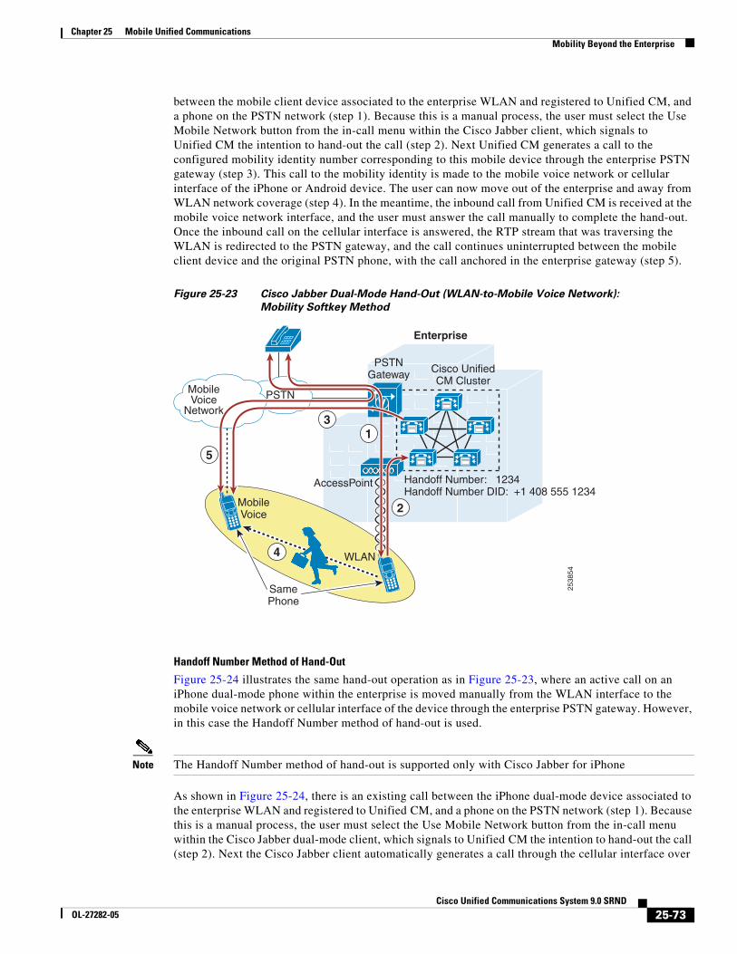
Chapter 25 Mobile Unified CommunicationsMobility Beyond the Enterprise
between the mobile client device associated to the enterprise WLAN and registered to Unified CM, and a phone on the PSTN network (step 1). Because this is a manual process, the user must select the Use Mobile Network button from the in-call menu within the Cisco Jabber client, which signals to Unified CM the intention to hand-out the call (step 2). Next Unified CM generates a call to the configured mobility identity number corresponding to this mobile device through the enterprise PSTN gateway (step 3). This call to the mobility identity is made to the mobile voice network or cellular interface of the iPhone or Android device. The user can now move out of the enterprise and away from WLAN network coverage (step 4). In the meantime, the inbound call from Unified CM is received at the mobile voice network interface, and the user must answer the call manually to complete the hand-out. Once the inbound call on the cellular interface is answered, the RTP stream that was traversing the WLAN is redirected to the PSTN gateway, and the call continues uninterrupted between the mobile client device and the original PSTN phone, with the call anchored in the enterprise gateway (step 5).
Figure 25-23 Cisco Jabber Dual-Mode Hand-Out (WLAN-to-Mobile Voice Network):
Mobility Softkey Method
Handoff Number Method of Hand-Out
Figure 25-24 illustrates the same hand-out operation as in Figure 25-23, where an active call on an iPhone dual-mode phone within the enterprise is moved manually from the WLAN interface to the mobile voice network or cellular interface of the device through the enterprise PSTN gateway. However, in this case the Handoff Number method of hand-out is used.
Note The Handoff Number method of hand-out is supported only with Cisco Jabber for iPhone
As shown in Figure 25-24, there is an existing call between the iPhone dual-mode device associated to the enterprise WLAN and registered to Unified CM, and a phone on the PSTN network (step 1). Because this is a manual process, the user must select the Use Mobile Network button from the in-call menu within the Cisco Jabber dual-mode client, which signals to Unified CM the intention to hand-out the call (step 2). Next the Cisco Jabber client automatically generates a call through the cellular interface over
MobileVoice
Network
2538
54
AccessPoint
V
PSTNGateway
SamePhone
Cisco UnifiedCM Cluster
Handoff Number: 1234Handoff Number DID: +1 408 555 1234
1
2MobileVoice
WLAN4
3
PSTN
Enterprise
5
25-73Cisco Unified Communications System 9.0 SRND
OL-27282-05
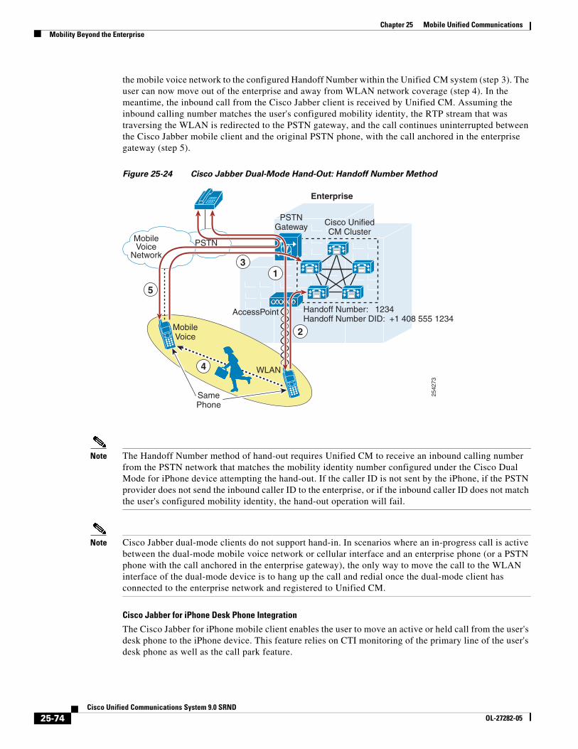
Chapter 25 Mobile Unified CommunicationsMobility Beyond the Enterprise
the mobile voice network to the configured Handoff Number within the Unified CM system (step 3). The user can now move out of the enterprise and away from WLAN network coverage (step 4). In the meantime, the inbound call from the Cisco Jabber client is received by Unified CM. Assuming the inbound calling number matches the user's configured mobility identity, the RTP stream that was traversing the WLAN is redirected to the PSTN gateway, and the call continues uninterrupted between the Cisco Jabber mobile client and the original PSTN phone, with the call anchored in the enterprise gateway (step 5).
Figure 25-24 Cisco Jabber Dual-Mode Hand-Out: Handoff Number Method
Note The Handoff Number method of hand-out requires Unified CM to receive an inbound calling number from the PSTN network that matches the mobility identity number configured under the Cisco Dual Mode for iPhone device attempting the hand-out. If the caller ID is not sent by the iPhone, if the PSTN provider does not send the inbound caller ID to the enterprise, or if the inbound caller ID does not match the user's configured mobility identity, the hand-out operation will fail.
Note Cisco Jabber dual-mode clients do not support hand-in. In scenarios where an in-progress call is active between the dual-mode mobile voice network or cellular interface and an enterprise phone (or a PSTN phone with the call anchored in the enterprise gateway), the only way to move the call to the WLAN interface of the dual-mode device is to hang up the call and redial once the dual-mode client has connected to the enterprise network and registered to Unified CM.
Cisco Jabber for iPhone Desk Phone Integration
The Cisco Jabber for iPhone mobile client enables the user to move an active or held call from the user's desk phone to the iPhone device. This feature relies on CTI monitoring of the primary line of the user's desk phone as well as the call park feature.
MobileVoice
Network
2542
73
AccessPoint
V
PSTNGateway
SamePhone
Cisco UnifiedCM Cluster
Handoff Number: 1234Handoff Number DID: +1 408 555 1234
1
2MobileVoice
WLAN4
3
PSTN
Enterprise
5
25-74Cisco Unified Communications System 9.0 SRND
OL-27282-05
Chapter 25 Mobile Unified CommunicationsMobility Beyond the Enterprise
The functionality provided by desk phone integration relies on active CTI monitoring of the primary line of the user's desk phone. Whenever an active or held call is sensed by the Cisco Jabber client, it prompts the user as to whether they want to transfer the call to the dual-mode device. If the user indicates they wish to transfer the call, the desk phone automatically parks the call and the mobile client automatically retrieves the call from the park number.
To enable desk phone integration, ensure that the user's end-user account is assigned to a CTI-enabled user group and that the user's desk phone is enabled to allow CTI control. In addition, the CTI Control Username field on the Cisco Dual-Mode for iPhone device must be configured with the user's end-user account userID.
Cisco Jabber for Android Desk Phone Integration
The Cisco Jabber for Android dual-mode client enables the user to move an active call from the Android device to the IP desk phone sharing a line with the mobile client device. This feature is invoked by placing the active call on hold through the Cisco Jabber client. When the call is placed on hold, the call can be resumed at either the shared-line IP desk phone or on the Cisco Jabber client.
WLAN Design Considerations for Cisco Jabber Mobile Clients
Consider the following WLAN guidelines when deploying Cisco Jabber mobile clients:
• Whenever possible, ensure that Cisco Jabber mobile clients roam on the WLAN only at Layer 2 so that the same IP address can be used on the WLAN interface of the device. In Layer 3 roaming scenarios where subnet boundaries are crossed due to device IP address changes, calls will be dropped.
• Deploy Cisco Jabber mobile clients on WLAN networks where the same SSID is used across all APs. Roaming between APs is much slower if SSIDs are different.
• Ensure all APs in the WLAN broadcast their SSID(s). If the SSID is not broadcast by the AP, the user may be prompted by the device to join other Wi-Fi networks or the device may automatically join other Wi-Fi networks. When this occurs the call is interrupted.
• Whenever possible, deploy Cisco Jabber mobile clients on the 5 GHz WLAN band (802.11a/n). 5 GHz WLANs provide better throughput and less interference for voice and video calls.
Interactions Between Cisco Jabber and Cisco Unified Mobility
The Cisco Jabber mobile clients can be integrated with Cisco Unified Mobility to leverage Cisco Mobile Connect, mid-call DTMF features, two-stage dialing, and single enterprise voicemail box mobile voicemail avoidance.
Integration with Unified Mobility requires the iPhone or Android dual-mode mobile phone number to be configured within Unified CM as a mobility identity associated with the Cisco Dual-Mode for iPhone or Cisco Dual-Mode for Android device. Once the mobile number is configured as a mobility identity within the system, Mobile Connect can be leveraged so that incoming calls to the user's enterprise number will be extended to the iPhone or Android dual-mode device through the mobile voice network as long as the iPhone or Android dual-mode device is not connected to the enterprise and not registered to Unified CM. In situations where the dual-mode device is connected to the enterprise and registered to Unified CM, an inbound call to the enterprise number will not be extended to the mobile voice network interface of the device. When the iPhone or Android dual-mode device is connected to the enterprise, only the WLAN or mobile data interface of the device will receive the inbound call. This prevents unnecessary consumption of enterprise PSTN gateway resources.
25-75Cisco Unified Communications System 9.0 SRND
OL-27282-05
Chapter 25 Mobile Unified CommunicationsMobility Beyond the Enterprise
When not connected to the enterprise and not registered to Unified CM, the iPhone or Android dual-mode device can invoke mid-call features by means of DTMF and perform desk phone pickup for any enterprise anchored call. The dual-mode device can also leverage Mobile Voice Access and Enterprise Feature Access two-stage dialing features when making outbound calls to route these calls through the enterprise and anchor them in the enterprise PSTN gateway.
In addition to configuring a mobility identity for the iPhone or Android dual-mode device, you can configure additional mobile phone numbers or off-system phone numbers as remote destinations and associate them to the Cisco Dual-Mode for iPhone or Cisco Dual-Mode for Android device within Unified CM. When associating the mobility identity and additional remote destinations to the dual-mode device, you do not have to configure a remote destination profile.
For more information about the Cisco Unified Mobility feature set as well as design and deployment considerations, see Cisco Unified Mobility, page 25-32.
Cisco Jabber for iPad
This section describes characteristics and deployment considerations for Cisco Jabber for iPad.
Cisco Jabber for iPad is a mobile client for the Apple iPad, and it provides voice and video calling capabilities as well as enterprise visual voicemail and directory access. The Cisco Jabber for iPad client also provides XMPP-based IM and presence when integrated to on-premises Cisco IM and Presence services or cloud-based collaboration services such as Cisco WebEx Messenger.
Once the client application is downloaded from the Apple Application Store and installed on the iPad device, it can connect to the enterprise network and register to Unified CM or Cisco TelePresence Video Communication Server (VCS) as a SIP enterprise endpoint. To provide registration and call control services to the Cisco Jabber iPad client, the device must be configured within Unified CM or VCS. When registering to Unified CM call control services, the client device is configured as a Cisco Jabber for Tablet device type. When registering to VCS call control services, the client device is configured and provisioned using the jabbertablet provisioning template and Cisco TelePresence Management Suite (TMS).
Next, the client device must be configured to access the enterprise WLAN for connectivity based on the enterprise WLAN infrastructure and security policies. Alternatively the device can be connected to the enterprise network through the mobile data network (if the device supports mobile provider data and if mobile data services are enabled) or over non-enterprise WLANs. Once the client device has been configured to access the enterprise network, when the Cisco Jabber for iPad client is launched, it will register the device to Unified CM or VCS for voice and video call control services.
The Cisco Jabber for iPad client is supported on the Apple iOS iPad 2 or the new iPad (third generation). WLAN interfaces of Apple iPad devices support 802.11a, 802.11b, 802.11g, and 802.11n.
For details on the latest specific device and firmware version support, refer to the product release notes at
http://www.cisco.com/en/US/products/ps12430/prod_release_notes_list.html
For more information about the Cisco Jabber for iPad client, additional feature details, and supported hardware and software versions, refer to the Cisco Jabber for iPad documentation at
http://www.cisco.com/en/US/products/ps12430/tsd_products_support_series_home.html
For more information about deploying Cisco Jabber for iPad, refer to the Cisco Jabber for iPad Deployment Guide, available at
http://www.cisco.com/en/US/products/ps12430/product_solution_overview_list.html
25-76Cisco Unified Communications System 9.0 SRND
OL-27282-05
Chapter 25 Mobile Unified CommunicationsMobility Beyond the Enterprise
Cisco Jabber IM
This section describes characteristics and deployment considerations for Cisco Jabber IM.
Cisco Jabber IM is an XMPP-based instant messaging (IM) and presence mobile client for Android, BlackBerry, iPhone, and other Apple iOS mobile devices. Once the client application is downloaded from the appropriate application store or download site (Apple Application Store, Google Play Store, or web) and installed on the Android, Apple iOS, or BlackBerry device, it can connect to the enterprise network for on-premises enterprise IM and presence services as provided by Cisco IM and Presence or to the Cisco WebEx Messenger service for off-premises enterprise IM and presence services. The mobile device must be configured to access the enterprise WLAN for connectivity based on the enterprise WLAN infrastructure and security policies. Alternatively the mobile device can be connected to the enterprise network through the mobile data network or over non-enterprise WLANs. Once the mobile device has been configured to access the enterprise network, when the Cisco Jabber IM client is launched, it will connect and register with the appropriate IM and presence service.
A Cisco Jabber IM client is available for most Android devices running Android 2.3, 4.0, or 4.1. A Cisco Jabber IM client is available for Apple iOS devices, including iPhone and iPad, with a minimum Apple iOS version of 4.2. A Cisco Jabber IM client is also available for a wide range of BlackBerry devices running BlackBerry OS 4.6 and later versions.
For more information on Cisco Jabber IM clients, refer to the following documentation:
• Cisco Jabber IM for BlackBerry data sheet
http://www.cisco.com/en/US/products/ps11763/products_data_sheets_list.html
• Cisco Jabber IM for Android data sheet
http://www.cisco.com/en/US/products/ps11678/products_data_sheets_list.html
• Cisco Jabber IM for iPhone data sheet
http://www.cisco.com/en/US/products/ps11596/products_data_sheets_list.html
Interactions Between Cisco Jabber IM and Cisco Jabber
The Cisco Jabber IM client enables escalation or cross-launch of the Cisco Jabber client (if installed) from the contact screen to an enterprise voice or video over IP call. In turn, the Cisco Jabber client is able to cross-launch Cisco Jabber IM (if installed) from the contact screen to an enterprise IM or chat.
Cisco Cius
This section describes characteristics and deployment considerations for Cisco Cius.
Cisco Cius is an Android-based enterprise tablet that provides native voice and video over WLAN or mobile data network when registered to Unified CM as a SIP enterprise device. To provide registration and call control services to the Cisco Cius native phone client, the device must be configured within Unified CM as a Cisco Cius device type. Next, the mobile device must be configured to access the enterprise WLAN for connectivity based on the enterprise WLAN infrastructure and security policies. Alternatively the mobile device can be connected to the enterprise network via the mobile data network if a mobile data network interface is available or over non-enterprise WLANs. Once the mobile device has been configured to access the enterprise network, when the Cius device is powered on, it will register the device to Unified CM.
The Cisco Cius supports not only voice calling but also video calling when connected with other Cius or other video-capable endpoints such as the Cisco Unified IP Phone 9971. As with other mobile clients and devices capable of voice and video over WLAN, Cisco recommends associating the Cius to the 5 GHz WLAN band (802.11a/n), which will provide better throughput and less interference for voice and video calls.
25-77Cisco Unified Communications System 9.0 SRND
OL-27282-05
Chapter 25 Mobile Unified CommunicationsMobility Beyond the Enterprise
For more information about deploying Cisco Cius wirelessly, including WLAN voice and video call capacity, refer to the Cisco Cius Deployment Guide, available at
http://www.cisco.com/en/US/products/ps11156/products_implementation_design_guides_list.html
The Cisco Cius also provides native support for enterprise directory access, enterprise visual voicemail, and XMPP-based IM and presence.
For more information about the Cisco Cius mobile device, additional feature and functionality details, and supported hardware and software versions, refer to the Cisco Cius product documentation available at
http://www.cisco.com/en/US/products/ps11156/tsd_products_support_series_home.html
Cisco AnyConnect Mobile Client
The Cisco AnyConnect mobile client provides secure remote connectivity capabilities for Cisco Cius and Cisco Jabber mobile device clients, enabling connectivity over mobile data networks and non-enterprise WLANs. The Cisco AnyConnect mobile client can be downloaded from the Apple Application Store or Google Play (formerly Android Market). Cisco AnyConnect is a native client application on the Cius. This client application provides SSL VPN connectivity for Apple iOS and Android mobile devices through the Cisco AnyConnect VPN solution available with the Cisco Adaptive Security Appliance (ASA) head-end.
When employing VPN network connectivity for connections over the mobile data network or public or private Wi-Fi hot spots, it is important to deploy a high-bandwidth secure VPN infrastructure that adheres to the enterprise's security requirements and policies. Careful planning is needed to ensure that the VPN infrastructure provides high bandwidth, reliable connections, and appropriate session or connection capacity based on the number of users and devices using this connectivity.
For more information on secure remote VPN connectivity using Cisco AnyConnect, refer to the Cisco AnyConnect Secure Mobile Client documentation available at
http://www.cisco.com/en/US/products/ps10884/tsd_products_support_series_home.html
High Availability for Cisco Mobile Clients and Devices
Although mobile devices and in particular dual-mode phones by their nature are highly available with regard to network connectivity (when the WLAN network is unavailable, the mobile voice and data networks can be used for voice and data services), enterprise WLAN and IP telephony infrastructure high availability must still be considered.
First, the enterprise WLAN must be deployed in a manner that provides redundant WLAN access. For example, APs and other WLAN infrastructure components should be deployed so that the failure of a wireless AP does not impact network connectivity for the mobile device. Likewise, WLAN management and security infrastructure must be deployed in a highly redundant fashion so that mobile devices are always able to connect securely to the network. Controller-based wireless LAN infrastructures are recommended because they enable centralized configuration and management of enterprise APs, thus allowing the WLAN to be adjusted dynamically based on network activity and AP failures.
Next, VPN infrastructure components, including the Cisco ASA head-end VPN or AnyConnect session terminator, should be deployed in a highly redundant fashion so that loss of a VPN session terminator does not impact or prevent remote secure enterprise connectivity for the mobile client.
Next, Unified CM call processing and registration service high availability must be considered. Just as with other devices within the enterprise that leverage Unified CM for call processing services, mobile client devices must register with Unified CM. Given the redundant nature of the Unified CM cluster
25-78Cisco Unified Communications System 9.0 SRND
OL-27282-05
Chapter 25 Mobile Unified CommunicationsMobility Beyond the Enterprise
architecture, which provides primary and backup call processing and device registration services, mobile device registration as well as call routing are still available even in scenarios in which a Unified CM server node fails.
Similar considerations apply to PSTN access. Just as with any IP telephony deployment, multiple PSTN gateways and call routing paths should be deployed to ensure highly available access to the PSTN. This is not unique to mobile client device deployments, but is an important consideration none the less.
Capacity Planning for Cisco Mobile Clients and Devices
Capacity planning considerations for Cisco mobile clients and devices, including dual-mode phones, are the same as for other IP telephony endpoints or devices that rely on the IP telephony infrastructure and applications for registration, call processing, and PSTN access services.
When deploying Cisco mobile clients and devices, it is important to consider the registration load on Unified CM as well as the Unified Mobility limits. A single Unified CM cluster is capable of handling a maximum of 40,000 device configurations and registrations. When deploying mobile clients and devices, you must consider the per-cluster maximum device support, and you might have to deploy additional call processing clusters to handle the added load.
In addition, as previously mentioned, the maximum number of remote destinations and mobility identities within a single Unified CM cluster is 15,000. Because most dual-mode mobile client devices will likely be integrated with Unified Mobility to take advantage of features such as Mobile Connect, single enterprise voicemail box mobile voicemail avoidance, desk phone pickup, and two-stage dialing, the mobile phone number of each of these dual-mode mobile devices must be configured as a mobility identity within the Unified CM cluster. This is necessary to facilitate integration to Unified Mobility as well as to facilitate handoff in some cases. Therefore, when integrating these dual-mode devices with Unified Mobility, it is important to consider the overall remote destination and mobility identity capacity of the Unified CM cluster to ensure sufficient capacity exists. If additional users or devices are already integrated to Unified Mobility within the system, they can limit the amount of remaining remote destination and mobility identity capacity available for dual-mode devices.
CTI capacity must also be considered when deploying the Cisco Jabber client for iPhone with desk phone integration. Because this feature relies on CTI monitoring of the primary line of the user's desk phone, each Cisco Jabber for iPhone mobility user enabled for desk phone integration will consume a CTI connection on the Unified CM system. This load must be considered in relation to the overall CTI capacity of the system.
Overall call processing capacity of the Unified CM or VCS system and PSTN gateway capacity must also be considered when deploying mobile client devices. Beyond handling the actual mobile device configuration and registration, these systems must also have sufficient capacity to handle the added BHCA impact of these mobile devices and users. Likewise, it is critical to ensure sufficient PSTN gateway capacity is available to accommodate mobile devices. This is especially the case for dual-mode mobile devices that are integrated to Unified Mobility because the types of users that would have dual-mode devices are typically highly mobile. Highly mobile users typically generate more enterprise PSTN gateway load from mobility features such as Mobile Connect, where an incoming call to a mobile user's enterprise number generates one or more calls to the PSTN, or from two-stage dialing, where a user makes a call through the enterprise by leveraging the enterprise PSTN gateway.
Finally, just as with enterprise mobility deployments, 802.11 WLAN call capacity must be considered when deploying Cisco mobile clients and device. As previously mentioned, a maximum of 27 VoWLAN calls or a maximum of 8 VVoWLAN calls are possible per 802.11 channel cell. This assumes no Bluetooth when devices are deployed on the 2.4 GHz band, 24 Mbps or higher data rates for VoWLAN calls, and 720p video resolution with bit rates up to 1 Mbps for VVoWLAN calls. Actual call capacity
25-79Cisco Unified Communications System 9.0 SRND
OL-27282-05
Chapter 25 Mobile Unified CommunicationsMobility Beyond the Enterprise
could be lower depending on the RF environment, wireless endpoint type, and WLAN infrastructure. See Capacity Planning for Campus Enterprise Mobility, page 25-9, for more details regarding 802.11 WLAN call capacity.
The above considerations are certainly not all unique to mobile clients and devices. They apply to all situations in which devices and users are added to Unified CM, resulting in additional load to the overall Unified Communications System.
For more information on general system sizing, capacity planning, and deployment considerations, see the chapter on Unified Communications Design and Deployment Sizing Considerations, page 29-1.
Design Considerations for Cisco Mobile Clients and Devices
Observe the following design recommendations when deploying Cisco mobile clients and devices:
• Dual-mode mobile devices must be capable of dual transfer mode (DTM) in order to be connected simultaneously to both the mobile voice and data network and the WLAN network so that the device is reachable and able to make and receive calls on both the cellular radio and WLAN interface of the device. In some cases, proper dual-mode client operation might not be possible if mobile voice and data networks do not support dual-connected devices.
• WLAN APs should be deployed with a minimum cell overlap of 20%. This overlap ensures that a mobile device can successfully roam from one AP to the next as the device moves around within a location, while still maintaining voice and data network connectivity.
• WLAN APs should be deployed with cell power level boundaries (or channel cell radius) of -67 dBm in order to minimize packet loss. Furthermore, the same-channel cell boundary separation should be approximately 19 dBm. A same-channel cell separation of 19 dBm is critical for ensuring that APs or clients do not cause co-channel interference to other devices associated to the same channel, which would likely result in poor voice and video quality.
• Whenever possible rely on the 5 GHz WLAN band (802.11a/n) for connecting mobile clients and devices capable of generating voice and video traffic. 5 GHz WLANs provide better throughput and less interference for voice and video calls.
• The enterprise wired and wireless LAN should be deployed and configured to support the necessary end-to-end QoS classes of service, including priority queuing for voice media and dedicated video and signaling bandwidth, to ensure the quality of client application voice and video calls and the appropriate behavior of all features. While most clients mark traffic appropriately at Layer 3 based on Cisco QoS recommendations, appropriate Layer 2 WLAN UP marking is dependent on the client device and vendor implementation. For this reason, Layer 2 marking is not consistent across platforms and as such cannot be relied upon.
• Because mobile devices are similar to desktop computers and can generate a large variety of data and real-time traffic, these devices are typically considered untrusted. For this reason, the network should be configured to re-mark all traffic from these client devices based on port number and/or protocol. Likewise, rate limiting and policing on ingress to the network is recommended.
• Cisco recommends using only an enterprise-class voice and video optimized WLAN network for connecting mobile devices and clients. While most mobile client devices are capable of attaching to public or private WLAN access points or hot spots for connecting back to the enterprise through the Internet for call control and other Unified Communications services, Cisco cannot guarantee voice and video quality for these types of connections.
25-80Cisco Unified Communications System 9.0 SRND
OL-27282-05
Chapter 25 Mobile Unified CommunicationsMobility Beyond the Enterprise
• When deploying Cisco collaboration mobile clients and devices on a Cisco Bring Your Own Device (BYOD) infrastructure, administrators should consider a network attachment method that does not require user intervention and which maximizes utilization of the IP telephony infrastructure. Further, for remote connectivity scenarios, all relevant ports must be opened in the corporate firewall in order for Cisco mobile clients and devices to be able to access collaboration services.
• If corporate policy dictates that the BYOD infrastructure must remotely wipe or factory-reset lost or stolen mobile devices, employees using personal mobile devices should be aware of the policy and should regularly back up personal data.
• The Unified Mobility Mobile Connect feature will not extend incoming calls to the dual-mode device's configured mobility identity if the dual-mode device is inside the enterprise and registered to Unified CM. This is by design in order to reduce utilization of enterprise PSTN resources. Because the dual-mode device registers to Unified CM, the system knows whether the device is reachable inside the enterprise; and if it is, there is no reason to extend the call to the PSTN in order to ring the dual-mode device's cellular voice radio. Only when the dual-mode device is unregistered will Mobile Connect extend incoming calls to the user's enterprise number out to the mobility identity number on the PSTN.
• When you deploy mobile devices, Cisco recommends normalizing required dialing strings so that users are able to maintain their dialing habits, whether the mobile device is connected to the enterprise or not. Because dialing on the mobile network is typically done using full E.164 (with or without a preceding '+') and mobile phone contacts are typically stored with full E.164 numbers, Cisco recommends configuring the enterprise dial plan to accommodate full E.164 or full E.164 with preceding '+' for mobile client devices. By configuring the enterprise dial plan in this manner, you can provide the best possible end-user dialing experience so that users do not have to be aware of whether the device is registered to Unified CM.
• Cisco recommends that dual-mode phone users rely exclusively on the mobile voice network for making emergency calls and determining device and user location. This is because mobile provider networks typically provide much more reliable location indication than WLAN networks. To ensure that dual-mode phones rely exclusively on the mobile voice network for emergency and location services, configure the Emergency Numbers field of the dual-mode devices within Unified CM with emergency numbers such 911, 999, and 112 in order to force these calls over the mobile voice network. Dual-mode phone users should be advised to make all emergency calls over the mobile voice network rather than the enterprise network. Although making emergency calls over corporate WLANs or mobile data networks is not recommended, mobile devices that do not have cellular voice radios are capable of making calls only through these data interfaces. Mobile devices that do not have cellular voice radios should not be relied upon for making emergency calls.
• When deploying Cisco Jabber for iPhone with desk phone integration, the end-user account for the Cisco Jabber user must be enabled for CTI. In addition, call park should be configured at a system level so that the desk phone can auto-park the call and the Cisco Jabber client can retrieve it whenever a call is moved from the desk phone to the Cisco Jabber client. CTI overhead of this feature should be considered when sizing the overall Unified CM system.
• When deploying Cisco Jabber for iPhone or Android mobile clients, configure the WLAN network to accommodate the following deployment guidelines:
– Minimize roaming of Cisco Jabber for iPhone and Android mobile devices at Layer 3 on the WLAN. Layer 3 roaming, where a device IP address changes, will result in longer roam times and dropped voice packets and could even result in dropped calls.
– Configure the same SSID across all APs utilized by the Cisco Jabber mobile client devices within the WLAN to ensure the fastest AP-to-AP roaming.
25-81Cisco Unified Communications System 9.0 SRND
OL-27282-05
Chapter 25 Mobile Unified CommunicationsMobility Beyond the Enterprise
– Configure all enterprise WLAN APs to broadcast their SSIDs in order to prevent mid-call prompts to join other APs within the WLAN infrastructure, which could result in interrupted calls.
• Provide sufficient wireless voice and video call capacity on the enterprise wireless network for Cisco mobile clients and devices by deploying the appropriate number of wireless APs to handle the desired call capacity based on mobility-enabled user BHCA rates. Each 802.11g/n (2.4 GHz) or 802.11a/n (5 GHz) channel cell can support a maximum of 27 simultaneous voice-only calls with 24 Mbps or higher data rates. Each 802.11g/n (2.4 GHz) or 802.11a/n (5 GHz) channel cell can support a maximum of 8 simultaneous video calls assuming 720p video resolution at up to 1 Mbps bit rate. For 2.4 GHz WLAN deployments, Bluetooth must be disabled to achieve this capacity. Actual call capacity could be lower depending on the RF environment, wireless endpoint type, and WLAN infrastructure.
25-82Cisco Unified Communications System 9.0 SRND
OL-27282-05