Embed Size (px)
Citation preview
Mobile Computing
Cellular Concepts
Cellular Networks • Wireless Transmission• Cellular Concept• Frequency Reuse• Channel Allocation• Call Setup• Cell Handoffs• Location Management
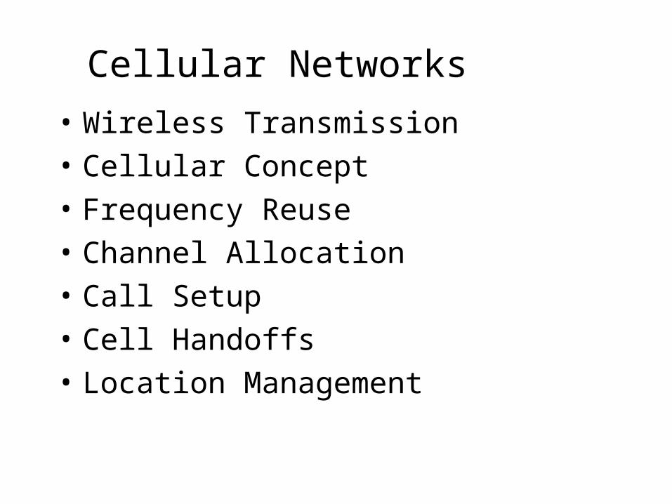
Basic Idea
• Single hop wireless connectivity to the wired world– Space divided into cells; A base station is
responsible to communicate with hosts in its cell
Wireless Transmission
• Communication Frequencies– Frequencies in the VHF range are used– Regulation bodies
• Antennas– Theoretically: equal radiation in all directions– Reality: directive effects, sectorized antennas
Wireless Transmission
• Signal Propagation– Classification: Analog/Digital, Periodic/Aperiodic– Parameters: Amplitude, Frequency and Phase shift
• Modulation Techniques– Amplitude, Frequency, Phase
• Multiplexing Mechanisms– Space (SDM), Frequency (FDM), Time (TDM), Code
(CDM)
Cellular Concept
• Mobile hosts can change cells while communicating– Hand-off occurs when a mobile host changes base
station• Factors for determining cell size
– No. of users to be supported– Multiplexing and transmission technologies
Cellular Concept
• Limited number of frequencies => limited channels• Single high power antenna => limited number of
users• Smaller cells => frequency reuse possible => more
number of users• As demand increases (more channels needed)
– Number of base stations is increased– Transmitter power is decreased
correspondingly to avoid interference

Cellular Concept
• Base stations (BS): implement space division multiplex– Each BS covers a certain transmission area (cell)– Each BS is allocated a portion of the total number of
channels available– Cluster: group of nearby BSs that together use all
available channels• Mobile stations communicate only via the base
station, using FDMA, TDMA, CDMA…
Cellular Concept
• Cell size:– 100 m in cities to 35 km on the country side
(GSM) – even less for higher frequencies

Cellular Concept
• Cell shape:– Hexagonal is useful for theoretical analysis– Practical footprint (radio coverage area) is
amorphous• BS placement:
– Center-excited cell: BS near center of cell • omni-directional antenna
– Edge-excited cell: BSs on cell vertices• sectored directional antennas
Cellular Concept
• Advantages:– higher capacity, higher number of users– less transmission power needed– more robust, decentralized– base station deals with interference, transmission
area etc. locally

Cellular Concept
• Problems:– fixed network needed for the base stations– handover necessary– interference with co-channel, adjacent-channel
• Important Issues:– Cell sizing; Frequency reuse planning– Channel allocation strategies
Bottom line: Attempt to maximize availability of channels in an area

Geometric Representation
• Cells are commonly represented by hexagons.
• Why hexagon? • How about circle?• How about square, or triangle?
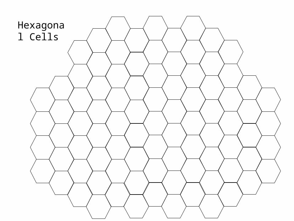
Hexagonal Cells
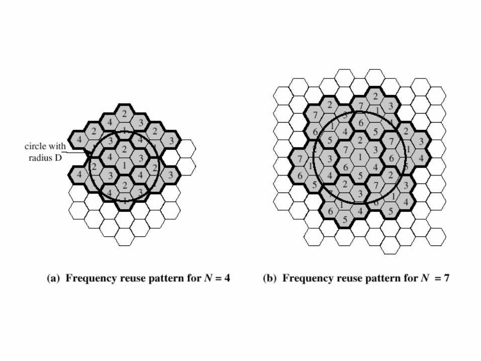
Channel Reuse
• The total number of channels are divided into K groups.– K is called reuse factor or cluster size.
• Each cell is assigned one of the groups.• The same group can be reused by two different
cells provided that they are sufficiently far apart.
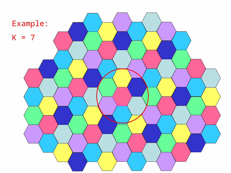
Example:
K = 7
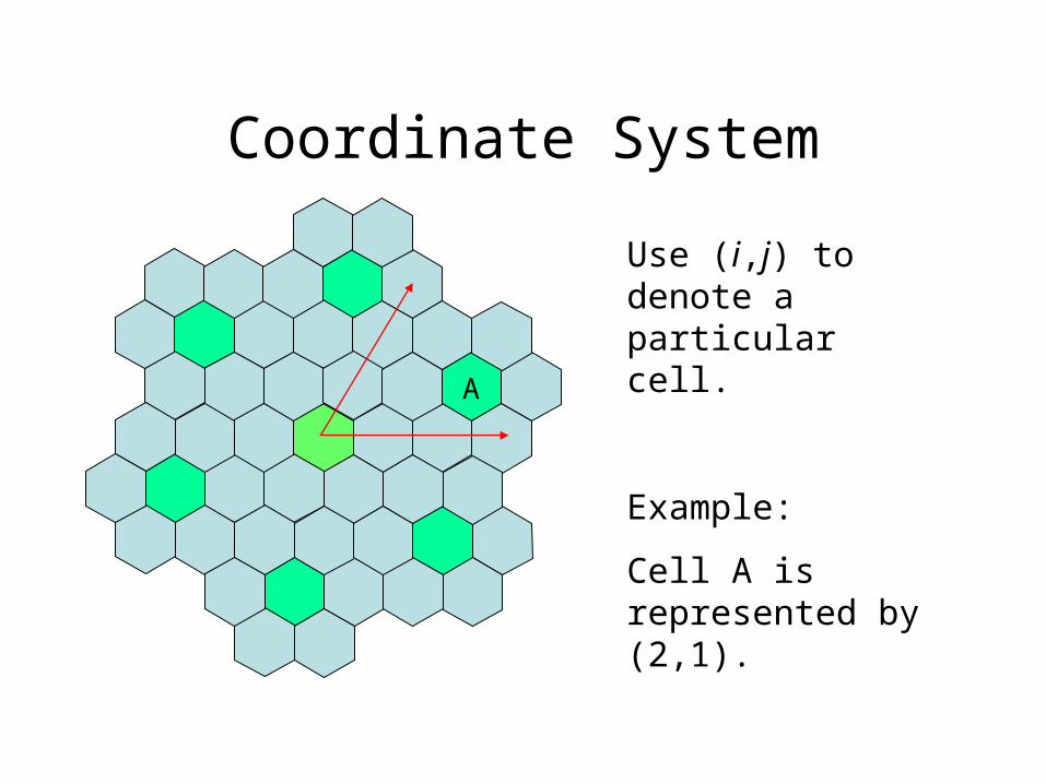
Coordinate System
Use (i,j) to denote a particular cell.
Example:
Cell A is represented by (2,1).
A
R D
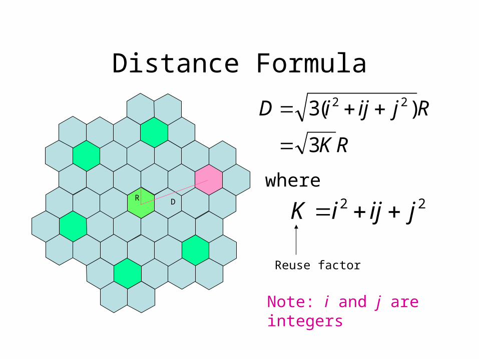
Distance Formula
RK
RjijiD
3
)(3 22
22 jijiK
Note: i and j are integers
where
Reuse factor
Cellular System Architecture
MSC MSC
HLR
VLR
HLR
VLR
To otherMSCs
PSTNPSTN
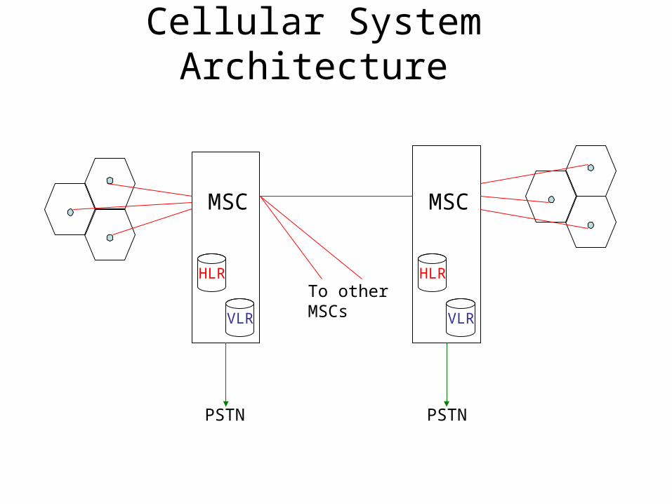
Cellular System Architecture
• Each cell is served by a base station (BS)• Each BS is connected to a mobile switching
center (MSC) through fixed links• Each MSC is connected to other MSCs and
PSTN

Cellular System Architecture• Each MSC is a local switching exchange that
handles switching of mobile user from one base station to another– Locating the current cell of a mobile user
• Home Location Register (HLR): database recording the current location of each mobile that belongs to the MSC
• Visitor Location Register (VLR): database recording the cell of “visiting” mobiles
– Interfacing with other MSCs and PSTN
Cellular System Architecture
• One channel in each cell is set aside for signalling information between BS and mobiles– Mobile-to-BS: location, call setup for outgoing,
response to incoming– BS-to-Mobile: cell identity, call setup for incoming,
location updating
Call Setup
• Outgoing call setup:– User keys in the number and presses send (no dial
tone)– Mobile transmits access request on uplink signaling
channel– If network can process the call, BS sends a channel
allocation message– Network proceeds to setup the connection
Call Setup (contd)
• Network activity:– MSC determines current location of target mobile
using HLR, VLR and by communicating with other MSCs
– Source MSC initiates a call setup message to MSC covering target area

Call Setup (contd)• Incoming call setup:
– Target MSC (covering current location of mobile) initiates a paging msg
– BSs forward the paging message on downlink channel in coverage area
– If mobile is on (monitoring the signaling channel), it responds to BS
– BS sends a channel allocation message and informs MSC
Hand-Offs
Mobile moves from one BS into another• BS initiated:
– BS monitors the signal level of the mobile– Handoff occurs if signal level falls below threshold– Increases load on BS
• Monitor signal level of each mobile• Determine target BS for handoff

Hand-Offs (contd)• Mobile assisted:
– Each BS periodically transmits beacon– Mobile, on hearing stronger beacon from a new BS,
sends it a greeting• changes routing tables to make new BS its
default gateway• sends new BS identity of the old BS
– New BS acknowledges the greeting and begins to route mobile’s call
Hand-Offs
• Intersystem: (Roaming)– Mobile moves across areas controlled by different
MSC’s– Handled similar to mobile assisted case with
additional HLR/VLR effort– Local call may become long-distance
Cellular Implementations
• First-generation: Analog cellular systems (450-900 MHz)– Frequency shift keying for signaling– FDMA for spectrum sharing– NMT (Europe), AMPS (US)
• Second-generation: Digital cellular systems (900, 1800 MHz)– TDMA/CDMA for spectrum sharing– Circuit switching– GSM (Europe), IS-136 (US), PDC (Japan)
Cellular Implementations
• 2.5G: Packet switching extensions– Digital: GSM to GPRS– Analog: AMPS to CDPD
• 3G:– High speed, data and Internet services– IMT-2000