Embed Size (px)
Citation preview

Bachelor’s Thesis Degree Program in Information Technology 2010
Chengcheng Li
Mobile Ad Hoc Network

ii
BACHELOR´S THESIS | ABSTRACT
UNIVERSITY OF APPLIED SCIENCES
Degree Program in Information Technology
Spring 2010 | 48
Vesa Slotte
Chengcheng Li
Mobile Ad Hoc Network As a new generation of wireless communication system, mobile ad-hoc network has
developed greatly during the past ten years. Endowed by great mobility, dynamic topology,
self-organizing and other unique features, it is commonly used in emergency operations,
disaster relief efforts and military networks. However, this new wireless network has lots of
technical challenges and potential benefits need to be discovered and conquered. Without a
doubt, we will soon be able to see ad-hoc network deployment everywhere in the near future.
This thesis first introduces the concept of mobile ad-hoc network including its main features,
network structure and applications. Then, it focuses on one of the key issues of the ad-hoc
network---routing. Finally, on-demand routing protocol (AODV, DSR, TORA) is selected and
compared in simulated small-scale networks by using the software OPNET Modeler, aiming to
find differences in their performances.
KEYWORDS:
Ad-hoc network, dynamic topology, self-organizing, network simulation
BACHELOR’S THESIS OF TURKU UNIVERSITY OF APPLIED SCIENCES | Chengcheng Li

iii
Table of Contents
Abstract ii
Table of Contents iii
Acronyms and abbreviations v
1 Introduction 1
1.1 Background of mobile ad hoc network and its value 1
2 Mobile Ad Hoc Network and its Routing Protocols 3
2.1 Overview 3
2.1.1 Conception 3
2.1.2 Features 3
2.1.3 Application 5
2.1.4 Routing protocol requirements 5
2.1.5 Network structure 8
2.2 Introduction of ad-hoc routing protocols 9
2.3 AODV Routing Protocol 11
2.3.1 Algorithm 11
2.3.2 Terminology 12
2.3.3 Packet format 14
2.3.4 Basic operation 16
2.4 DSR Routing Protocol 19
2.5 TORA Routing Protocol 22
3 Simulation Tool and Model 24
3.1 Overview 24
3.2 Introduction 24
3.2.1 What is OPNET Modeler 24
3.2.2 Feature 26
3.3 AODV Framework 27
BACHELOR’S THESIS OF TURKU UNIVERSITY OF APPLIED SCIENCES | Chengcheng Li

iv
3.3.1 Network mode 27
3.3.2 Node mode 28
3.3.3 Process mode 29
4 OPNET-based Simulation 32
4.1 Evaluation parameters 32
4.2 Analysis of three protocols 33
4.2.1 DSR 33
4.2.2 TORA 35
4.2.3 AODV 36
4.2.4 Overall analysis 39
5 Summary and Outlook 42
5.1 Evaluation 42
5.2 Outlook 44
References 45
Appendices 47
BACHELOR’S THESIS OF TURKU UNIVERSITY OF APPLIED SCIENCES | Chengcheng Li

BACHELOR’S THESIS OF TURKU UNIVERSITY OF APPLIED SCIENCES | Chengcheng Li
v
Acronyms and abbreviations
AODV Ad-hoc On-demand Distance Vector Routing
ARP Address Resolution Protocol
CDMA Code Division Multiple Access
DSDV Destination Sequence Distance Vector routing protocol
DSR Dynamic Source Routing
FTP File Transfer Protocol
GPRS General Packet Radio Service
GSM Global System for Mobile Communication
IMEP Internet MANET Encapsulation Protocol
IP Internet Protocol
MAC Media Access Control
OSI Open System Interconnection
PAN Personal Area Network
TCP Transmission Control Protocol
TORA Temporally Ordered Routing Algorithm
TTL Time to Live
WLAN Wireless Local Area Network
WRP Wireless Routing Protocol

1
Chapter 1 Introduction
1.1 The background of Mobile Ad Hoc Network and its value
Mobile Ad Hoc Networking is a technology under development for the last 20
years principally through research funding sponsored by the U.S Government.
It is somewhat synonymous with Mobile Packet Radio Networking (a term
coined via during early military research in the 70's and 80's), Mobile Mesh
Networking (a term that appeared in an article in The Economist regarding the
structure of future military networks) and Mobile, Multihop, Wireless,
Networking (perhaps the most accurate term, although a bit cumbersome). In
the 1990s, the concept of commercial ad-hoc networks arrived with notebook
computers and other viable communications equipment. At the same time, the
idea of a collection of mobile nodes was proposed at several research
conferences. The IEEE 802.11 subcommittee had adopted the term "ad-hoc
networks" and the research community had started to look into the possibility
of deploying ad-hoc networks in other areas of application. Meanwhile, work
was going on to advance the previously built ad-hoc networks. GloMo (Global
Mobile Information Systems) and the NTDR (Near-term Digital Radio) are
some of the results of these efforts. [1][2]GloMo was designed to provide an
office environment with Ethernet-type multimedia connectivity anywhere and
anytime in handheld devices.
Later on in mid-1990s, within the Internet Engineering Task Force (IETF), the
Mobile Ad-Hoc Networking working group was formed to standardize routing
protocols for ad-hoc networks. [3]The development of routing within the
working group and the larger community resulted in the invention of reactive
and proactive routing protocols.
BACHELOR’S THESIS OF TURKU UNIVERSITY OF APPLIED SCIENCES | Chengcheng Li

2
Soon after, the IEEE 802.11 subcommittee standardized a medium access
protocol that was based on collision avoidance and tolerated hidden terminals,
making it usable for building mobile ad hoc networks prototypes out of
notebooks and 802.11 PCMCIA cards. HyperLAN and Bluetooth were some
other ad-hoc network standards that addressed and benefited ad-hoc
networking. [4][5]
As a new technology for information acquisition, the mobile ad-hoc network is
of high research value and wide application prospects. It has become hot off
the press in the last ten years in the globe. Owing to its mobility, dynamic
topology, equivalence, self-organizing and other unique features, it has great
advantages in emergency communications and military mobile
communications.
Routing is one of the core issues in mobile ad-hoc network. An effective
routing mechanism will be helpful to extend the successful deployment of
mobile ad-hoc network. In this thesis, a brief introduction of the mobile ad-hoc
network definition, main features, network structure and applications will be
given in the first place. Then, three existing pro-active routing protocols (AODV,
DSR, TORA) will be presented including their algorithms, terminology,
message format and operation process. The main content of this paper is
trying to compare these three protocols’ performance in emulated small-scale
networks based on the software OPNET Modeler.
BACHELOR’S THESIS OF TURKU UNIVERSITY OF APPLIED SCIENCES | Chengcheng Li

3
Chapter 2 Mobile Ad Hoc Network and its Routing
Protocols
2.1 Overview
2.1.1 Conception of MANET
Ad hoc is a Latin phrase which means “for this purpose”. It generally signifies a
solution designed for a specific problem or task. Mobile ad hoc network, known
as MANET by IETF, is an autonomous collection of mobile users that
communicate over relatively bandwidth constrained wireless links [6]. Since
the nodes are mobile, the network topology may change rapidly and
unpredictably over time. The network is decentralized, where all network
activity including discovering the topology and delivering messages must be
executed by the nodes themselves, i.e. routing functionality will be
incorporated into mobile nodes.
2.1.2 Features
A MANET consists of multiple free nodes which can move about arbitrarily. The
nodes maybe located in or on transportations including aeroplanes, ships,
trucks, cars, perhaps even on people or very small devices, and there may be
multiple hosts per router. A MANET is an autonomous system of mobile nodes
which may operate in isolation, or may have gateways to and interface with a
fixed network.
MANETs have several notable characteristics: [7]
BACHELOR’S THESIS OF TURKU UNIVERSITY OF APPLIED SCIENCES | Chengcheng Li

4
(1) Dynamic topologies: Nodes are free to move randomly; thus the network
topology which is typically multihop, may change randomly and rapidly at
unpredictable times, and may consist of both bidirectional and unidirectional
links.
(2) Energy-constrained operation: Some or all of the nodes in a MANET may
rely on batteries or other exhaustible means for their energy. For these nodes,
the most important system design criteria for optimization may be energy
conservation.
(3) Bandwidth-constrained & variable capacity links: Wireless links will have
significantly lower capacity than their hardwired counterparts. Furthermore,
after accounting for the effects of multiple access, fading, noise, and
interference conditions, the realized throughput of wireless communications is
often much less than a radio's maximum transmission rate.
(4) Limited physical security: Mobile wireless networks are generally more
prone to physical security threats than fixed-cable nets. The increased
possibility of eavesdropping, spoofing, and denial-of-service attacks needs to
be carefully considered. Existing link security techniques are often applied
within wireless networks to reduce security threats. As a benefit, the
decentralized nature of network control in MANETs provides additional
robustness against the single points of failure of more centralized approaches.
[8]
These characteristics create a set of underlying assumptions and performance
concerns for protocol design which are distinguished from those guiding the
design of routing within the higher-speed, semi-static topology of the fixed
Internet.
BACHELOR’S THESIS OF TURKU UNIVERSITY OF APPLIED SCIENCES | Chengcheng Li

5
2.1.3 Application
Ad-hoc networks are suited for use in situations where an infrastructure is
unavailable or to deploy one is not cost-effective. One of many possible uses
of mobile ad-hoc networks is in some business environments, where the need
for collaborative computing might be more important outside the office
environment than inside, such as in a business meeting outside the office to
brief clients on a given assignment. [2]
A mobile ad-hoc network can also be used to provide crisis management
services applications, such as in disaster recovery, where the entire
communication infrastructure is destroyed and recovering communication
quickly is crucial. By using a mobile ad-hoc network, an infrastructure could be
set up in hours instead of weeks, as is required in the case of wired line
communication. Another application example of a mobile ad-hoc network is
Bluetooth, which is designed to support a personal area network by eliminating
the need of wires between various devices, such as printers and personal
digital assistants. The famous IEEE 802.11 or Wi-Fi protocol also supports an
ad-hoc network system in the absence of a wireless access point [18].
2.1.4 Routing protocol performance issues
The routing protocols of MANET have to meet certain QoS requirements. The
following is a list of desirable qualitative properties of MANET routing protocols
[9]:
(1) Loop-freedom: It is not required in light of certain quantitative measures but
it is generally desirable to avoid problems such as worst-case phenomena, e.g.
a small fraction of packets spinning around in the network for arbitrary time
BACHELOR’S THESIS OF TURKU UNIVERSITY OF APPLIED SCIENCES | Chengcheng Li

6
periods. Ad hoc solutions such as TTL values can solve the problem, but a
more structured and well-formed approach is generally needed as it usually
brings better overall performance.
(2) Distributed operation: This is an essential property of MANET that the
protocol has to own.
(3) Proactive operation: This is the flip-side of demand-based operation. In
certain contexts, the additional latency demand-based operation incurs may be
unacceptable. If bandwidth and energy resources permit, proactive operation
is desirable in these contexts.
(4) Demand-based operation: Instead of assuming a uniform traffic distribution
within the network (and maintaining routing between all nodes at all times), the
routing algorithm adapts to the traffic pattern on a demand or need basis. If
this is done intelligently, it can utilize network energy and bandwidth resources
more efficiently, at the cost of increased route discovery delay.
(5) Unidirectional link support: Bidirectional links are typically assumed in the
design of routing algorithms, and many algorithms are incapable of functioning
properly over unidirectional links. Nevertheless, unidirectional links can and do
occur in wireless networks. Often, a sufficient number of duplex links exist so
that usage of unidirectional links is of limited added value. However, in
situations where a pair of unidirectional links (in opposite directions) form the
only bidirectional connection between two ad hoc regions, the ability to make
use of them is valuable.
(6) Security: Without some form of network-level or link-layer security, a
MANET routing protocol is vulnerable to many forms of attack. It may be
relatively simple to snoop network traffic replay transmissions, manipulate
BACHELOR’S THESIS OF TURKU UNIVERSITY OF APPLIED SCIENCES | Chengcheng Li

7
packet headers, and redirect routing messages within a wireless network
without appropriate security provisions. While these concerns exist within
wired infrastructures and routing protocols as well, maintaining the "physical"
security of the transmission media is harder in practice with MANETs.
Sufficient security protection to prohibit disruption of modification of protocol
operation is desired. This may be somewhat orthogonal to any particular
routing protocol approach, e.g. through the application of IP Security
techniques.
(7) "Sleep" period operation: As a result of energy conservation, or some other
need to be inactive, nodes of a MANET may stop transmitting and/or receiving
(even receiving requires power) for arbitrary time periods. A routing protocol
should be able to accommodate such sleep periods without overly adverse
consequences. This property may require close coupling with the link-layer
protocol through a standardized interface.
The following is a list of quantitative metrics that can be used to assess the
performance of any routing protocol. [10]
(1) Route Acquisition Time: It is the time required to establish route when
requested and it is usually being used for on-demand routing protocols.
(2) End-to-end data throughput and delay: Statistical measures of data routing
performance (e.g., means, variances, distributions) are important as they can
be used as measures of a routing policy's effectiveness
(3) Efficiency: To achieve a given level of data routing performance, two
different policies can expend differing amounts of overhead, depending on
their internal efficiency. Protocol efficiency may or may not directly affect data
routing performance. If control and data traffic must share the same channel,
BACHELOR’S THESIS OF TURKU UNIVERSITY OF APPLIED SCIENCES | Chengcheng Li

8
and the channel's capacity is limited, then excessive control traffic often
impacts data routing performance. [7]
(4) Percentage Out-of-Order Delivery: An external measure of connectionless
routing performance of particular interest to transport layer protocols such as
TCP which prefer in-order delivery.
2.1.5 Network Structure
A mobile ad-hoc network is a collection of mobile devices equipped with a
transmitter and receiver, connected in the absence of fixed infrastructure. A
mobile ad-hoc network is defined with characteristics such as purpose-specific,
autonomous and dynamic [11]. In comparison with fixed wireless networks,
there is no master-slave relationship that exists in a mobile ad-hoc network.
Nodes rely on each other to established communication, thus each node acts
as a router. Therefore, in a mobile ad-hoc network, a packet can travel from a
source to a destination either directly, or through some set of intermediate
packet forwarding nodes.
The control and management of a mobile ad-hoc network is distributed among
the participating nodes [12]. Each node is responsible for forwarding packets to
other nodes in the networks. The nodes also collaborate themselves to
implement network routine functions such as security. Nodes in a mobile
ad-hoc network are highly mobile which causes the network topology to
change rapidly and unpredictably, as can be seen in Figure 2.1
BACHELOR’S THESIS OF TURKU UNIVERSITY OF APPLIED SCIENCES | Chengcheng Li

9
Figure 2.1 Mobile ad-hoc network on the left constructs itself as needed [2]
2.2 Introduction of ad-hoc routing protocols
Routing protocols of mobile ad-hoc network tend to need different approaches
from existing internet protocols, since most of the existing internet protocols
were designed to support routing in a network with fixed structure. Existing
ad-hoc routing protocols can be divided into two types: table-driven protocols
and on-demand routing protocols.
Figure 2.2 Categorization of Ad Hoc Routing Protocols
• Table-driven protocols
Table-driven protocols are one of the old ways of acquiring routing in mobile
ad-hoc networks. These protocols maintain a consistent overview of the
BACHELOR’S THESIS OF TURKU UNIVERSITY OF APPLIED SCIENCES | Chengcheng Li

10
network. Each node uses routing tables to store the location information of
other nodes in the network. This information is used to transfer data among
various nodes of the network.
To ensure the freshness of the routing tables, these protocols adopt different
methods. One of the adopted methods is broadcasting "hello," a special
message containing address information, at fixed intervals of time. On
receiving this message, each node updates its routing tables with real time
locations information of other participating nodes. Destination Sequence
Distance Vector routing protocol (DSDV), Wireless Routing Protocol (WRP)
and Cluster-head Gateway Switch Routing (CGSR) are some of the popular
table-driven protocols for mobile ad-hoc networks.
Table-driven protocols might not be considered an effective routing solution for
mobile ad-hoc network. Nodes in mobile ad-hoc networks operate with low
battery power and with limited bandwidth. Presence of high mobility, large
routing tables and low scalability result in consumption of bandwidth and
battery life of the nodes. Moreover continuous updates could create
unnecessary network overhead.
• On-demand routing protocols
Another member in the family of routing protocols for mobile ad-hoc network is
on-demand routing protocols. With on-demand protocols, if a source node
requires a route to the destination for which it does not have route information,
it initiates a route discovery process which goes from one node to the other
until it reaches the destination or an intermediate node that has a route to the
destination.
BACHELOR’S THESIS OF TURKU UNIVERSITY OF APPLIED SCIENCES | Chengcheng Li

11
It is the responsibility of the route request receiver node to reply back to the
source node about the possible route to the destination [22]. The source node
uses this route for data transmission to the destination node. Some of the
better known on-demand protocols are Ad-hoc On-demand Distance Vector
routing (AODV), Dynamic Source Routing (DSR) and Temporary Ordered
Routing Algorithm (TORA).
These protocols differ in storing the previously known route information and in
how they use the established route data. Again, in a network with many
participating nodes we may suffer from the same kind of problems that we
have seen in table-driven protocols.
2.3 AODV routing protocol
2.3.1 AODV algorithm
AODV is a pure on-demand route acquisition algorithm. In other words, nodes
that do not lie on active paths neither maintain any routing information nor
participate in any periodic routing table exchanges [14]. Further, a node does
not have to discover and maintain a route to another node until the two need to
communicate unless the former node is offering services as an intermediate
forwarding station to maintain connectivity between two other nodes.
There are three message types in AODV routing algorithm, Route Requests
(RREQs), Route Replies (RREPs), and Route Errors (RERRs) [14]. When a
route to a new destination is needed, the node broadcasts a RREQ to find a
route to the destination. A route can be determined when the RREQ reaches
either the destination itself, or an intermediate node with a ‘fresh enough’ route
to the destination (a route is ‘fresh enough’ when the sequence number of this
route is at least as great as that contained in the RREQ). The route is made
BACHELOR’S THESIS OF TURKU UNIVERSITY OF APPLIED SCIENCES | Chengcheng Li

12
available by unicasting a RREP back to the origination of the RREQ. Each
node receiving the request caches a route back to the originator of the request,
so that the RREP can be unicast from the destination along a path to that
originator. When a link break in an active route is detected, a RERR message
is used to notify other nodes that the loss of that link has occurred. After
receiving the error message, other nodes will aware of the routing error and
find a new reachable link.
2.3.2 AODV Terminology
Active route: It is a route towards a destination that has a routing table entry
that is marked as valid. Only active routes can be used to forward data
packets.
Broadcast: Broadcasting means transmitting to the IP Limited Broadcast
address, 255.255.255.255. A broadcast packet may not be blindly forwarded,
but broadcasting is useful in enabling dissemination of AODV messages
throughout the ad hoc network.
Destination: It is an IP address to which data packets are to be transmitted. It
is the same as "destination node". A node knows it is the destination node for
a typical data packet when its address appears in the appropriate field of the IP
header. Routes for destination nodes are supplied by action of the AODV
protocol, which carries the IP address of the desired destination node in route
discovery messages.
Forwarding node: It is a node that agrees to forward packets destined for
another node, by retransmitting them to a next hop that is closer to the unicast
destination along a path that has been set up using routing control messages.
BACHELOR’S THESIS OF TURKU UNIVERSITY OF APPLIED SCIENCES | Chengcheng Li
13
Forward route: It is a route set up to send data packets from a node
originating a Route Discovery operation towards its desired destination.
Invalid route: It is a route that has expired, denoted by a state of invalid in the
routing table entry. An invalid route is used to store previously valid route
information for an extended period of time. An invalid route cannot be used to
forward data packets, but it can provide information useful for route repairs,
and also for future RREQ messages.
Originating node: It is a node that initiates an AODV route discovery
message to be processed and possibly retransmitted by other nodes in the ad
hoc network. For instance, the node initiating a Route Discovery process and
broadcasting the RREQ message is called the originating node of the RREQ
message.
Reverse route: It is a route set up to forward a reply (RREP) packet back to
the originator from the destination or from an intermediate node having a route
to the destination.
Sequence number: It is a monotonically increasing number maintained by
each originating node. In AODV routing protocol messages, it is used by
other nodes to determine the freshness of the
information contained from the originating node. [7]
BACHELOR’S THESIS OF TURKU UNIVERSITY OF APPLIED SCIENCES | Chengcheng Li

14
2.3.3 Message Format
(1)RREQ Message Format
Figure 2.3 RREQ Message Format
Type: 7
Hop count: The number of hops from the originator IP address to the node
handling the request.
TTL: Time to Live of the message.
G: Gratuitous RREP flag; indicates whether a gratuitous RREP should be
unicast to the node specified in the destination IP address field.
SrcSeqNb: The current sequence number to be used in the route entry
pointing towards the originator of the route request.
DEST: The IP address of the destination for which a route is desired.
DestSeqNb:The latest sequence number received in the past by the
BACHELOR’S THESIS OF TURKU UNIVERSITY OF APPLIED SCIENCES | Chengcheng Li

15
originator for any route towards the destination.
(2)RREP Message Format
Figure 2.4 RREP Message Format
Type: 11
A: Acknowledgment required.
GeneratingNode: The node that generate the route reply.
Source: The IP address of the node which originated the RREQ for which the
route is supplied.
DEST: The IP address of the destination for which a route is desired.
Lifetime: The time in milliseconds for which nodes receiving the RREP
consider the route to be valid.
BACHELOR’S THESIS OF TURKU UNIVERSITY OF APPLIED SCIENCES | Chengcheng Li

16
(3)RERR Message Format
Figure 2.5 RERR Message Format
Type: 13
N: No delete flag; set when a node has performed a local repair of a link, and
upstream nodes should not delete the route.
DestCount: The number of unreachable destinations included in the message;
must be at least 1.
2.3.4 Operations
(1)Route request processing
When a source node desires to send a message to some destination node and
does not already have a valid route to that destination, it initiates a path
discovery process to locate the other node. It broadcasts a route request
(RREQ) packet to its neighbors, which then forward the request to their
neighbors, and so on, until either the destination or an intermediate node with
a “fresh enough” route to the destination is located. Figure 2.6a illustrates the
BACHELOR’S THESIS OF TURKU UNIVERSITY OF APPLIED SCIENCES | Chengcheng Li

17
propagation of the broadcast RREQs across the network. AODV utilizes
destination sequence numbers to ensure that all routes are loop-free and
contain the most recent route information. Each node maintains its own
sequence number, as well as a broadcast ID. The broadcast ID is incremented
for every RREQ the node initiates, and together with the node’s IP address,
uniquely identifies an RREQ. Along with its own sequence number and the
broadcast ID, the source node includes in the RREQ the most recent
sequence number it has for the destination. Intermediate nodes can reply to
the RREQ only if they have a route to the destination whose corresponding
destination sequence number is greater than or equal to that contained in the
RREQ.
Figure 2.6 AODV Route Discovery [14]
During the process of forwarding the RREQ, intermediate nodes record in their
route tables the address of the neighbor from which the first copy of the
broadcast packet is received, thereby establishing a reverse path. If additional
copies of the same RREQ are later received, these packets are discarded.
(2)Route reply processing
Once the RREQ reaches the destination or an intermediate node with a fresh
enough route, the destination/intermediate node responds by unicasting a
route reply (RREP) packet back to the neighbor from which it first received the
RREQ (Fig. 2.6b). As the RREP is routed back along the reverse path, nodes
BACHELOR’S THESIS OF TURKU UNIVERSITY OF APPLIED SCIENCES | Chengcheng Li

18
along this path set up forward route entries in their route tables which point to
the node from which the RREP came. These forward route entries indicate the
active forward route. Associated with each route entry is a route timer which
will cause the deletion of the entry if it is not used within the specified lifetime.
Because the RREP is forwarded along the path established by the RREQ,
AODV only supports the use of symmetric links.
(3)Connection management and maintenance
Routes are maintained as follows. If a source node moves, it is able to
reinitiate the route discovery protocol to find a new route to the destination. If a
node along the route moves, its upstream neighbor notices the move and
propagates a link failure notification message (an RREP with infinite metric) to
each of its active upstream neighbors to inform them of the erasure of that part
of the route. These nodes in turn propagate the link failure notification to their
upstream neighbors, and so on until the source node is reached. The source
node may then choose to re-initiate route discovery for that destination if a
route is still desired.
An additional aspect of the protocol is the use of hello messages, periodic local
broadcasts by a node to inform each mobile node of other nodes in its
neighborhood. Hello messages can be used to maintain the local connectivity
of a node. However, the use of hello messages is not required. Nodes listen for
retransmission of data packets to ensure that the next hop is still within reach.
If such a retransmission is not heard, the node may use any one of a number
of techniques, including the reception of hello messages, to determine whether
the next hop is within communication range. The hello messages may list the
other nodes from which a mobile has heard, thereby yielding greater
knowledge of network connectivity.
BACHELOR’S THESIS OF TURKU UNIVERSITY OF APPLIED SCIENCES | Chengcheng Li

19
2.4 DSR Routing Protocol
Likewise, DSR and TORA are types of on-demand routing protocols. A brief
introduction of DSR and TORA will be given in the following paragraphs.
The basic version of DSR uses explicit "source routing", in which each data
packet sent carries in its header the complete, ordered list of nodes through
which the packet will pass [21]. This use of explicit source routing allows the
sender to select and control the routes used for its own packets, supports the
use of multiple routes to any destination (for example, for load balancing), and
allows a simple guarantee that the routes used are loop-free. By including this
source route in the header of each data packet, other nodes forwarding or
overhearing any of these packets can also easily cache this routing information
for future use. [15]
Basic operations of DSR include route discovery and route maintenance.
Route discovery process mainly helps the source node to obtain the route to
the destination node. When the node can not guarantee reaching the
destination node due to movement, shutdown, or other reasons, the current
rode is no longer valid. The aim of route maintenance is to monitor the
availability of current route. When routing failure occurs, it will call a new round
of route discovery.
2.4.1 Route discovery
When a source node originates a new packet addressed to some destination
node, the source node places in the header of the packet a "source route"
giving the sequence of hops that the packet is to follow on its way to the
BACHELOR’S THESIS OF TURKU UNIVERSITY OF APPLIED SCIENCES | Chengcheng Li

20
destination. Normally, the sender will obtain a suitable source route by
searching its "Route Cache" of routes previously learned; if no route is found in
its cache, it will initiate the Route Discovery protocol to dynamically find a new
route to this destination node [7]. In this case, we call the source node the
"initiator" and the destination node the "target" of the Route Discovery.
To initiate the route discovery, the source node transmits a “route request” as a
single local broadcast packet, which is received by all nodes currently within
wireless transmission range of itself. Each route request identifies the initiator
and target of the route discovery, and also contains a unique request
identification, determined by the initiator of the request. Each route request
also contains a record listing the address of each intermediate node through
which this particular copy of the route request has been forwarded.
When another node receives this route request, if it is the target of the route
discovery, it returns a “route relay” to the initiator of the route discovery, giving
a copy of the accumulated route record from the route request; when the
initiator receives this route reply, it caches this route in the route cache for use
in sending subsequent packets to this destination.
Figure 2.7 DSR Routing Discovery [16]
BACHELOR’S THESIS OF TURKU UNIVERSITY OF APPLIED SCIENCES | Chengcheng Li
21
2.4.2 Route maintenance
When originating or forwarding a packet using a source route, each node
transmitting the packet is responsible for confirming the data can flow over the
link from that node to the next hop. An acknowledgement can provide
confirmation that a link is capable of carrying data, and in wireless networks,
acknowledgements are often provided at no cost, either as an existing
standard part of the MAC protocol in use, or by a “pass acknowledgement”.
This means that if the existing acknowledgement mechanism is not available,
the node transmitting the packet can explicitly request that a DSR-specific
software acknowledgement be returned by the next node along the route.
This software acknowledgement will normally be transmitted directly to the
sending node, but if the link between these two nodes is unidirectional, this
software acknowledgement could travel over a different, multi-hop path.
After the acknowledgement request has been retransmitted the maximum
number of times and if no acknowledgement has been received, then the
sender treats the link to this next-hop destination as currently “broken”. The
sender should remove this link from its route cache and should return a “route
error” to each node that has sent a packet routed over that link since an
acknowledgement was last received.
2.5 TORA Routing Protocol
The Temporary Ordered Routing Algorithm (TORA) is a highly adaptive
loop-free distributed routing algorithm based on the concept of link reversal.
TORA is proposed to operate in a highly dynamic mobile networking
environment. It is source-initiated and provides multiple routes for any desired
source/destination pair. The key design concept of TORA is the localization of
BACHELOR’S THESIS OF TURKU UNIVERSITY OF APPLIED SCIENCES | Chengcheng Li

22
control messages to a very small set of nodes near the occurrence of a
topological change. To accomplish this, nodes need to maintain routing
information about adjacent (one-hop) nodes. The protocol performs three
basic functions: [13] (a) Route creation, (b) Route maintenance, (c) Route
erasure.
Figure 2.8 Establishing a DAG [16]
During the route creation and maintenance phases, nodes use a “height”
metric to establish a directed acyclic graph (DAG) rooted at the destination.
Thereafter, links are assigned a direction (upstream or downstream) based on
the relative height metric of neighboring nodes, as shown in Fig 2.8. This
process of establishing a DAG is similar to the query/reply process proposed in
Lightweight Mobile Routing (LMR). In times of node mobility, the DAG route is
broken, and route maintenance is necessary to re-establish a DAG rooted at
the same destination. As shown in Fig 2.8, upon failure of the last downstream
link, a node generates a new reference level which results in the propagation
of that reference level by neighboring nodes, effectively coordinating a
structured reaction to the failure. Links are reversed to reflect the change in
adapting to the new reference level. This has the same effect as reversing the
direction of one or more links when a node has no downstream links.
BACHELOR’S THESIS OF TURKU UNIVERSITY OF APPLIED SCIENCES | Chengcheng Li

23
One significant factor for TORA is timing because the “height” metric is
dependent on the logical time of a link failure; TORA assumes that all nodes
have synchronized clocks. TORA’s metric includes five elements, namely: [13]
• Logical time of a link failure
• The unique ID of the node that defined the new reference level
• A reflection indicator bit
• A propagation ordering parameter
• The unique ID of the node
In TORA there is a potential for oscillations to occur, especially when multiple
sets of coordinating nodes are concurrently detecting partitions, erasing routes,
and building new routes based on each other. Because TORA uses intermodal
coordination, its instability problem is similar to the “count-to-infinity” problem in
distance-vector routing protocols, except that such oscillations are temporary
and route convergence will ultimately occur.
BACHELOR’S THESIS OF TURKU UNIVERSITY OF APPLIED SCIENCES | Chengcheng Li

24
Chapter 3 Simulation Tool and Model
3.1 Overview
At the present day, it is almost impossible to design an integral networking
system just based on theoretical calculation. However, if we conduct the study,
design and development in a real network environment, we will not only incur
high, but also have difficulties with data collection and analysis. In practical
work, it is prevalent to use network simulation software to simulate and
estimate network performance. Software, such as NS2 and OPNET, can adjust
network parameters in the simulated environment to achieve maximum
utilization. Compared to NS2, OPNET is more reliable and it has powerful
built-in modules which include a variety of application protocol as well as
models of real communication equipments. To run a simulation, users just
need to select the appropriate models and link them relevantly in the editor
with the graphic user interface. In this thesis, the most popular network
simulation software OPNET Modeler is used to simulate the mobile ad hoc
network and compare performance.
3.2 Introduction
3.2.1 What is OPNET Modeler?
OPNET was first created in 1986 by two Ph.Ds. from Massachusetts Institute
of Technology and the commercial OPNET was established in 1987. Currently
there are about 2700 OPNET users which spread all over fields including
enterprises, internet service providers, device manufacturers as well as military,
education, banking and insurance [19]. The company's first product was
BACHELOR’S THESIS OF TURKU UNIVERSITY OF APPLIED SCIENCES | Chengcheng Li

25
OPNET Modeler, a software tool for network modeling and simulation. Among
all series of OPNET products, Modeler has an all-sided functionality. It works
for different purposes in different areas: for enterprise network simulation, all
types of emulation devices can be used to build the specific network. If the
response time of the operations like online transactions, database and other
business, is slower than the normal conditions, Modeler can find the
bottlenecks from service, network and server by capturing and analyzing the
critical data flow; For ISP networks, Modeler focuses on the service and traffic
simulation so that the service provider can identify the errors in the
configuration effectively; also, Modeler provides an open environment that
allows users to create new protocols and devices, define and simulate every
details of them for the research purposes.
Figure 3.1 GUI interface of OPNET
BACHELOR’S THESIS OF TURKU UNIVERSITY OF APPLIED SCIENCES | Chengcheng Li

26
3.2.2 Features
OPNET Modeler supports different layer modeling and provides a wide range
of development interface. It has the following features [20]:
(1) Hierarchical network modeling
It adopts a form of hierarchical network modeling. From the protocol aspect,
the node modeling follows the OSI model: Application layer->TCP layer->IP
layer->IP encapsulation layer->ARP layer->MAC layer->Physical layer.
(2) Simple modeling mechanisms
The modeling process can be divided into three layers: the bottom layer is
the Process Model, using the state machine to describe protocols; the
second layer is the Node Model, constructed by the corresponding protocol
model, reflecting the characteristics of the device; the top layer is the
Network Model. It is made up by nodes and the link between the nodes.
Network topology can be set up by this layer of model directly. The 3-layer
models fully correspond to the real protocol, device and network, thus,
reflect every feature of the network.
(3) Finite State Machine (FSM)
Modeler uses a powerful finite state machine approach to support detailed
specification of protocols, resources, applications, algorithms, and queuing
policies. Users are able to include analytical model by programming it using
the C language and finally FSM is a representative of the process flow of
the code for specific process level (buffer/queue, processor, etc).
(4) Usable and wide ranging protocols
OPNET Modeler provides up to 400 library functions and concise protocol
model. A large number of widely used protocols have been embedded in
BACHELOR’S THESIS OF TURKU UNIVERSITY OF APPLIED SCIENCES | Chengcheng Li

27
the system’s core and it is easy to use them without any programming.
(5) Support variety of application model
OPNET predefined almost all the commonly used application model,
including Homogeneous Distribution, Poisson Distribution, Binomial
Distribution and other 22 distributions. Users can also sample the real
operations, and make it a probability density function in the editor provided
by OPNET for simulation input.
(6) Total openness
All the code and protocols are completely open to the user and every node
has a clear notation which enables easy customization and modification of
the models including the hooks to easily create models from scratch.
3.3 AODV Framework
As previously mentioned, we divide AODV emulation to three layers. The first
one is the network layer. We construct the topology based on the numbers of
nodes and the distance between them. Next, a description of different types of
node model will be made according to the OSI model. The third layer is
focused on every process. The following example is given in a small network:
3.3.1 Network model
The network consists of four nodes, which are SOURCE, intermediate_node,
mobile_node and DESTINATION. They are distributed in a 10*10 km
rectangular area, communicating via wireless link as shown in Figure 3.2:
BACHELOR’S THESIS OF TURKU UNIVERSITY OF APPLIED SCIENCES | Chengcheng Li
28
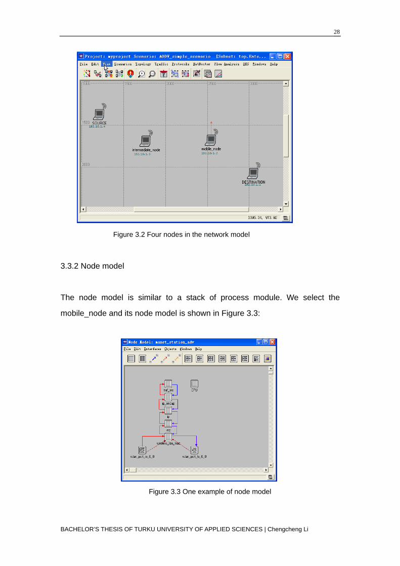
Figure 3.2 Four nodes in the network model
3.3.2 Node model
The node model is similar to a stack of process module. We select the
mobile_node and its node model is shown in Figure 3.3:
Figure 3.3 One example of node model
BACHELOR’S THESIS OF TURKU UNIVERSITY OF APPLIED SCIENCES | Chengcheng Li

29
The process module here represents the OSI model. The nodes are divided
into six layers which are wlan_port_rx_0_0 、 wlan_port_tx_0_0 、
wireless_lan_mac、arp、ip、ip_encap and traf_src from the lowest to the
highest.
Traf_src is used to generate the data packet to the lower layer, and forward or
destroy the packet that the lower layer already processed.
Ip and ip_encap belongs to the network layer. Module ip is a protocol designed
for communicating in the computer network, and ip_encap encapsulates for
the ip datagram.
Wireless_lan_mac is in data link layer. It has various functions including
preparing for the data sent from the upper layer and dealing with the different
conditions taking place in the transmitter and receiver. The MAC layer has lots
of parameters to be set. Most of the parameters are significant in wireless LAN.
Parameters need to be set: data transfer rate is 11kbps; sending power is
0.005w, buffer size (bits) is set to 256000 bits.
Wlan_port_rx_0_0 and wlan_port_tx_0_0 constitute physical layer. The
wireless receiver is the Wlan_port_rx_0_0, while wlan_port_tx_0_0 is the
wireless transmitter.
3.3.3 Process mode
The process mode is built up by a finite state machine programmed by C code.
The process mode of wireless_lan_mac is shown in Figure 3.4:
BACHELOR’S THESIS OF TURKU UNIVERSITY OF APPLIED SCIENCES | Chengcheng Li

30
Figure 3.4 One example of process model
Init is the initial state, which is the default state in the beginning of the
emulation. It initializes some variable and parameters in the routing protocol
(such as routing table) and reads the predefined attributes.
Bss_init leads the emulation core into the MAC process.
Idle does not carry out any operations. It shifts to the corresponding state after
the incidents happen, otherwise any operations done in other states, system
will automatically shift to this state.
Frm_end processes the data packet sent from the upper layer. It includes
deciding whether to send RTS, or ACK, or wait for response.
Wait_for_response wait for response after sending the data. If there is no echo,
the system will check if there is time out situation in the timer or data collision.
BACHELOR’S THESIS OF TURKU UNIVERSITY OF APPLIED SCIENCES | Chengcheng Li

31
Defer handles any potential conflict while the system core is available.
Bkoff_needed decides whether the sending frame needs to step back. This
state is used when the physical layer is busy or when judging whether there is
a conflict in the data transmission.
Backoff determines the number of frames that need to back off.
Transmit processes the frame transmission.
Scan decapsulates the MAC header of the packet in order to forward it to the
upper layer.
BACHELOR’S THESIS OF TURKU UNIVERSITY OF APPLIED SCIENCES | Chengcheng Li

32
Chapter 4 OPNET-based Emulation
4.1 Evaluation Parameters
The commonly used performance indicators in an Ad-hoc network are as
follows:
·Load: It represents all control packets sent by the nodes in the network for the
discovering and maintaining the route during the emulation. Loading ability can
be used to compare the scalability, efficiency as well as the competence of
adapting network congestion in different networks. Routing protocols with large
loading capability have more probability of packet collision and delay.
Average delay: This indicator refers the average lag time of the packet
travelling from the source node to the destination node. It includes the buffer
delay in the route discovery, the sending delay in the MAC layer and the
transmission time.
Route discovery time: It refers to the whole discovery time after the node
receives the reply.
Throughput: It is the total accumulated number of bits that all the destination
nodes have received in the MANET station.
Number of Hops per Route: It is the number of hops each sources node to
each destination node in the network.
Routing Traffic Sent and Received: It refers to the total amount of packet
BACHELOR’S THESIS OF TURKU UNIVERSITY OF APPLIED SCIENCES | Chengcheng Li

33
sent and received in the entire network.
FTP Download Response Time: It is the response time which the application
layer receives the reply after it sends the request to the server when
downloading.
FTP Upload Response Time: It is the response time that the application layer
receives the reply when uploading.
4.2 Analysis
We selected different evaluation indicators according to different emulation
models with AODV, TORA and DSR protocols.
4.2.1 DSR
We established two emulation ad-hoc networks with 50 nodes and 100 nodes
respectively with DSR routing protocol. These nodes were both placed in a
10*10km area. Both networks were running FTP service and the emulation
time is one hour. We used Routing Traffic Sent and Receive, Route discovery
time, Number of Hops per Route as parameters.
Figure 4.1 Figure 4.2
BACHELOR’S THESIS OF TURKU UNIVERSITY OF APPLIED SCIENCES | Chengcheng Li

34
Figures 4.1 and 4.2 illustrates that, with the increase in the number of nodes,
the number of packets sent and received is ascending. This is because in the
network which has 100 nodes, and the number of its adjacent nodes to each
node is more than that in the 50-nodes network. Therefore, when sending
routing information, every node has to send more packets to its adjacent nodes
in the former network. So the same happens with the received packets.
Figure 4.3 Figure 4.4
From Figure 4.3 we can see that, regardless of the number of nodes, the route
discovery time is relatively long in the beginning of the emulation, as there is
no route information in the cache. As the time goes by, discovery time
decreases gradually and then levels off. The reason for that is that DSR use
caching mechanisms which can store the nodes’ known routing information in
order to shorten the discovery time.
As for Figure 4.4, the number of hops per route is up to 9 times in the 100-node
network in the first 5 minutes. When the emulation just begins, the best route is
not found yet, thus the hop count is rather large. As the running time increases,
the hop count becomes stable slowly at about 4-5 times. However, due to
fewer nodes, the average hop count ranges between 2 and 3 hops in 50-node
BACHELOR’S THESIS OF TURKU UNIVERSITY OF APPLIED SCIENCES | Chengcheng Li

35
network.
4.2.2 TORA
Likewise, we then established two emulation ad-hoc networks with 50 nodes
and 100 nodes respectively with TORA routing protocol. These nodes were
placed in a 10*10km area. Both networks were running FTP service and the
emulation time was one hour. In this circumstance, we used the load of the
wireless LAN, IMEP traffic sent and received as the indicators.
Figure 4.5
From Figure 4.5, in the beginning, the loading ability is small in both networks.
As the time goes by, the line patterns are growing manifestly with the similar
speed. The more nodes there are, the more routing the network can load. As a
result, a 100-node network almost has the figures twice as that of a 50-node
network in later time.
BACHELOR’S THESIS OF TURKU UNIVERSITY OF APPLIED SCIENCES | Chengcheng Li

36
Figure 4.6 Figure 4.7
Figures 4.6 and 4.7 show that, IMEP traffic in the 100-node network is more
than double the IMEP traffic in the 50-node network. Similarly, having more
nodes in a network means that each node has more destinations to send
packets and also receives more routing information from its adjacent nodes.
4.2.3 AODV
In this section, we made three different scenarios with AODV routing protocol.
Each of them consists of 50 nodes distributed in a 10*10km area.
Preferences Scenario I Scenario II Scenario III
Gratuitous Route Reply Disabled Enabled Disabled
Active Route Timeout 3 sec 30 sec 30 sec
Hello Interval uniform (1,1.1) uniform (10,10.1) uniform (10,10.1)
Allowed Hello Loss 2 10 10
TTL Parameter:TTL
start
1 2 2
Figure 4.8 Settings in different scenarios
BACHELOR’S THESIS OF TURKU UNIVERSITY OF APPLIED SCIENCES | Chengcheng Li

37
Figure 4.9
In Figure 4.9, regardless of the scenario, it took relatively long time to discover
the route. Because of on-demand trait, it is difficult to find the suitable route to
the destination node. Moreover, it also takes time for AODV routing protocol to
create the routing table. As soon as the routing table has been established, the
route discovery time thus decreases. Compared to the first scenario, the
enabled gratuitous route is the reason why the second scenario has the
shortest discovery time. On the contrary, although the third scenario disabled
gratuitous route replay as the one in the first scenario, its longer timeout and
more hello packet loss as well as the larger TTL value made the longest
average route discovery time in the three scenarios.
Figure 4.10 Figure 4.11
BACHELOR’S THESIS OF TURKU UNIVERSITY OF APPLIED SCIENCES | Chengcheng Li

38
Figures 4.10 and 4.11 demonstrate the routing traffic of the three scenarios.
The same number of bits were sent and received in scenario II and III in the
graph as the two line overlap. That is because they have the same uniform of
hello interval and TTL value. The reason why the network in scenario I has a
much more traffic is that it have much shorter hello packet interval and timeout
value.
Figure 4.12 Figure 4.13
From Figure 4.12 and 4.13, it is obvious that scenario II has the shorter upload
and download response time than that in scenario I. We attribute this to the
enlarged TTL start value, longer active route timeout as well as the activated
gratuitous route replay. Also we can see a similar pattern of download
response time in scenario II and III but upload response time is varying. As the
gratuitous route replay is disabled, the server needs to find the response of the
intermediate node by launching its own route.
4.2.4 Performance comparison of three protocols
For the purpose of comparing the merits and drawbacks of each protocol, we
create three scenarios with DSR, TORA and AODV respectively. Each network
BACHELOR’S THESIS OF TURKU UNIVERSITY OF APPLIED SCIENCES | Chengcheng Li
39
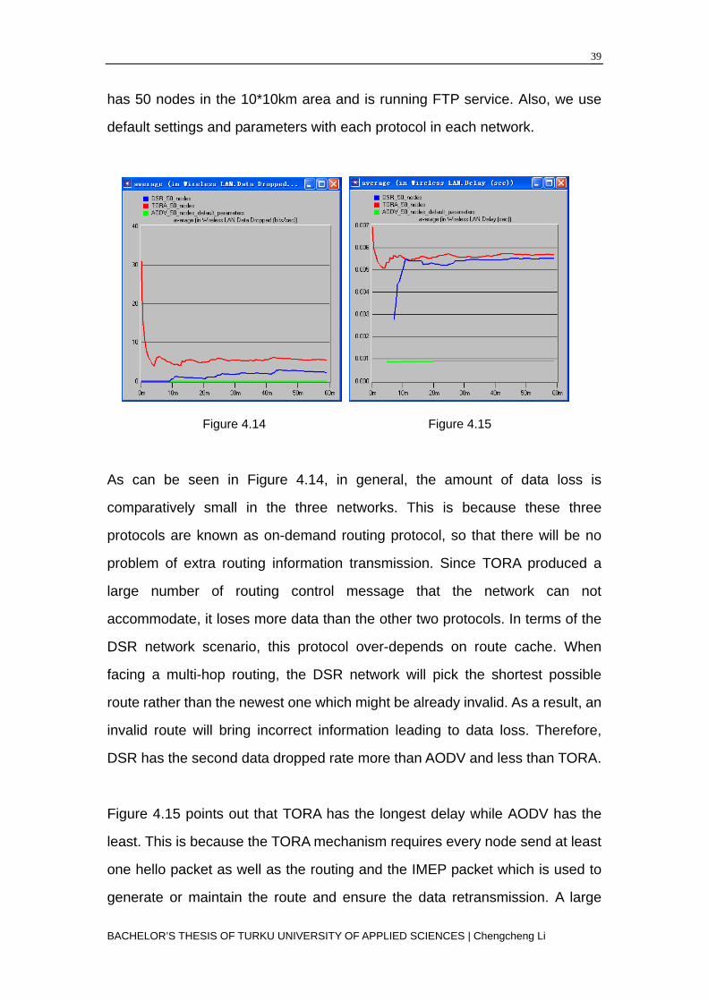
has 50 nodes in the 10*10km area and is running FTP service. Also, we use
default settings and parameters with each protocol in each network.
Figure 4.14 Figure 4.15
As can be seen in Figure 4.14, in general, the amount of data loss is
comparatively small in the three networks. This is because these three
protocols are known as on-demand routing protocol, so that there will be no
problem of extra routing information transmission. Since TORA produced a
large number of routing control message that the network can not
accommodate, it loses more data than the other two protocols. In terms of the
DSR network scenario, this protocol over-depends on route cache. When
facing a multi-hop routing, the DSR network will pick the shortest possible
route rather than the newest one which might be already invalid. As a result, an
invalid route will bring incorrect information leading to data loss. Therefore,
DSR has the second data dropped rate more than AODV and less than TORA.
Figure 4.15 points out that TORA has the longest delay while AODV has the
least. This is because the TORA mechanism requires every node send at least
one hello packet as well as the routing and the IMEP packet which is used to
generate or maintain the route and ensure the data retransmission. A large
BACHELOR’S THESIS OF TURKU UNIVERSITY OF APPLIED SCIENCES | Chengcheng Li

40
quantity of control messages thus brings about the long delay.
There are two reasons why AODV has much less delay than DSR. Firstly DSR
uses route cache and source-routing mode which stores multiple route
information to the destination node from a single node, while each node in
AODV only holds one valid route to the destination node. Moreover it
addresses every node with a serial number to avoid the loop and keep routing
table updated. Secondly, AODV uses shorter time creating a route than DSR
does.
Figure 4.16 Figure 4.17
Figure 4.16 shows the loading ability of the three protocols. DSR is seen to be
the one with the lightest load. Source-routing packets constitute part of the
network load so that there is limited space for other packet transmissions.
However, TORA provides multiple routes and it sends more control messages
so it has a larger load than DSR. AODV is considered to have a much larger
load than the other two because it consumes fewer resources on channel
acquisition.
Similarly, owing to the DSR’s routing cache and source-routing mechanism,
BACHELOR’S THESIS OF TURKU UNIVERSITY OF APPLIED SCIENCES | Chengcheng Li

41
route discovery and maintenance can be intermittent depending on the
situation. There is no periodic broadcasting either. If there is no message to
deliver, the traffic in the network can be zero. So DSR has the smallest
throughput. TORA provides multiple routes for data transmission so it has
better transmission speed and load. AODV uses the routing table and serial
number mechanism to prevent loop. This algorithm has the largest throughput
due to its fast speed with route creation and broken link restoration.
BACHELOR’S THESIS OF TURKU UNIVERSITY OF APPLIED SCIENCES | Chengcheng Li

42
Chapter 5 Conclusion and Outlook
5.1 Evaluation
I.TORA
Advantages:
(1) It supports multiple routes to any source or destination pair. Failure or
removal of one node is quickly resolved without source intervention by
switching to an alternate route [16].
(2) It has good algorithm distributions which make it highly adaptive in a
dynamic network.
Disadvantages:
(1) It relies on synchronized clocks among nodes in the network. While
external time sources are present (GPS, for example), it makes the hardware
supporting it more costly, and introduces a single point of failure if the time
source becomes unavailable.
(2) TORA also depends on intermediate lower layers for certain functionality. It
assumes such as neighbor discovery, link status sensing, address resolution
and in-order packet delivery are all readily available. As a result, it is necessary
to run the IMEP at the layer immediately below TORA. This makes the
overhead for this protocol difficult to separate from that imposed by the
required lower layer.
II. DSR
BACHELOR’S THESIS OF TURKU UNIVERSITY OF APPLIED SCIENCES | Chengcheng Li

43
Advantages:
(1) The caching of any overheard or initiated routing data can significantly
reduce the number of control messages being sent, thus reducing overhead.
(2) Since the entire route is contained in the packet header, no routing tables
must be kept to route a given packet. It saves power and bandwidth because
there is no communication overhead in the network.
Disadvantages:
(1) DSR is not scalable to large networks as the Internet-Drafts in IETF
acknowledge that the protocol assumes that the diameter of the network is no
greater than 10 hops.
(2) Multiple route information in the cache will occasionally affect the accuracy
of the routing selection.
(3) It requires significantly more processing resources than most other
protocols. In order to obtain routing information, each node has to spend much
more time processing any control data it receives, even if it is not the intended
recipient.
III. AODV
Advantages:
(1) One advantage of AODV is that its use of destination numbers and replies
to the first arriving RREQ implies that AODV favors the least congested route
instead of the shortest route.
(2) The usage of hello protocol yields a greater knowledge of the network and
can improve the route discovery process.
(3) AODV is a modification of the Destination-sequenced Distance Vector
(DSDV) algorithm. The idea is simple and easy for people to understand.
BACHELOR’S THESIS OF TURKU UNIVERSITY OF APPLIED SCIENCES | Chengcheng Li

44
(4) Another advantage is that the drafted standard supports both unicast and
multicast packet transmissions.
In conclusion, although the three protocols have their own merits and
drawbacks, from comparison in the figures above, it is obvious that AODV is a
more efficient protocol which is best suited for general mobile ad-hoc networks
as it consumes less bandwidth and lower overhead when compared to other
two protocols.
Due to limited time and complexity in network simulation process, only three
protocols are presented in this article. While it is not clear that any particular
algorithm or class of algorithm is the best for all scenarios, each protocol has
definite advantages and disadvantages, and is well suited for certain
situations.
5.2 Outlook
Unlike fixed wireless networks, current internet protocols are not sufficient
enough to meet the operational requirements of ad-hoc networks. This new art
of network formation has a lot of potential benefits and may be able to change
the whole art of wireless communication. The field of ad-hoc mobile networks
is rapidly growing and changing. There are still many challenges that need to
be meet and lack of efficient strategies to handle various network controls is
one of them. However, in the light of ongoing efforts and the growing interest in
mobile ad-hoc network, we are not very far from seeing such networks in
widespread use in the near future.
BACHELOR’S THESIS OF TURKU UNIVERSITY OF APPLIED SCIENCES | Chengcheng Li

45
References
[1] Ming, C. (2004). OPNET Network Simulation. Beijing: Tsinghua University
Press.
[2] [www-document]. Available at: http://www.computingunplugged.com,
referred on 10.1.2010
[3] Humayun, B. (2005, Sep 6). The history of mobile ad-hoc networks.
Computing unplugged.
[4] [www-document]. Available at: http://www.computingunplugged.com,
referred on 10.1.2010
[5] Haitao, W. & Shaoren, Z. (2002). Peer-to-peer system based on Ad hoc
network. Communication Express, p.10.
[6] [www-document]. Available at: http://www.ieee802.org/11/ Jan.2005,
referred on 10.1.2010
[7] Corson, S. & Macker, J. (1999) “Mobile Ad hoc Networking
(MANET):Routing Protocol Performance Issues and Evaluation
Considerations”, IETF rfc2501
[8] Xiaoyan, H., Kaixin, Xu. & Mario, G. (2002). “Scalable Routing Protocol for
Mobile Ad hoc Networks”. IEEE Network.
[9] Joao, L.S. & Krishnakumar, A.S. (1999) “Quality-of-Service in Ad-hoc
Carrier Sense Multiple Access Wireless Networks”, IEEE Journal On Selected
Areas In Communications, Vol.17, No.8.
[10] Macker, J. & Corson, M.S. (2001) “Mobile Ad Hoc Networking and IETF”,
ACM Mobile Computing and Communication Review 2.
[11] Lidong, Z. & Zygmunt, J.H. (1999) “Securing Ad Hoc Networks”, Network,
IEEE Volume 13, Issue 6, pp, 24-30.
[12] Phone Lin, Wei-Ru, Chai-Hien, G. (2004) “Modeling Opportunity Driven
Multiple Access in UMTS”, IEEE Transactions on Wireless Communications,
Vol.3, No.5.
BACHELOR’S THESIS OF TURKU UNIVERSITY OF APPLIED SCIENCES | Chengcheng Li

46
[13] Elizabeth, M.R. & Chai-keong, T. (1999) “A Review of Current Routing
Protocols for Ad Hoc Mobile Wireless Networks”, IEEE Personal
Communications.
[14] Perkins, C. Belding-Royer, E. & Das, S. (2003) “Ad Hoc On-Demand
Distance Vector (AODV) Routing”, IETF rfc3561.
[15] Krishna, G. (2006) “Routing Protocols in Mobile Ad-hoc Networks”,
Master’s Thesis in Computer Science, Umea University.
[16] Anne, A. & Jie, W. (2000-2001) “Performance Comparison of Ad-hoc
Routing Protocols for Networks with Node Energy Constraints” EE360 Class
Project
[17] Subir, K. & Das, C.S. (2002) “Weight Based Multicast Routing Protocol for
Ad hoc Wireless Networks”. Global Telecommunications Conference.
GLOBECOM’02. IEEE Volume 1, pp17-21, pp117-121 vol.1
[18] [www-document]. Available at: http://w3.antd.nist.gov/wahn_mahn.shtml,
referred on 10.1.2010
[19] Wenbo, W. & Jinwen, Z. (2003). OPNET Modeler and Network Simulation.
Beijing: Posts & Telecom Press.
[20] [www-document]. Available at: http://blog.baisi.net, referred on 10.1.2010
[21] Chun, Y. & Meilin, S. (1999) “Ad Hoc Network Architecture” Journal of
Communication, Vol.20, No.9
[22] Hubert, Z. (1980) IEEE Transactions on Communications, Vol 28, No.4,
p.425.
[23] Leiner, B.M. Ruther, R.J. & Sastry, A.R. (1996) “Goals and challenges of
the DARPA GloMo program”. Personal Communications, IEEE Volume 3,
Issue 6, pp 34-43.
[24][www-document].Available at: http://www.argreenhouse.com, referred on
10.1.2010
[25] [www-document]. Available at: http:// searchnetworking.techtarget.com,
referred on 10.1.2010
BACHELOR’S THESIS OF TURKU UNIVERSITY OF APPLIED SCIENCES | Chengcheng Li

47
Appendices
OSI model
Open system interconnect (OSI) is a network interconnection model developed
by International Organization of Standardization in 1985 to achieve a better
generalization of network application. [22]
GloMo
The Defense Advanced Research Projects Agency (DARPA) initiated the
Global Mobile Information Systems (GloMo) program in 1994 to develop and
demonstrate technologies to support these requirements. The GloMo project
has focused on developing new wireless ad hoc networking technologies.
These new technologies rely on a broad and varied set of techniques to help
cope with the problems inherent in the wireless environment. It deals with
issues ranging from underlying radio and signal processing technology through
middleware to support of mobile applications. [23]
NTDR
The Near Term Digital Radio (NTDR) System is an Army open architecture
networked data radio serving as a backbone for Platoon to Brigade that utilizes
commercial modules and a standard bus. The NTDR System Architecture
employs a two-tier hierarchical network concept designed to increase capacity
and reduce multiple access interference and relay delays. [24]
HyperLAN
HyperLAN stands for "High Performance Radio Local Area Network", and is a
Wireless LAN standardised by the European Telecommunication
BACHELOR’S THESIS OF TURKU UNIVERSITY OF APPLIED SCIENCES | Chengcheng Li

BACHELOR’S THESIS OF TURKU UNIVERSITY OF APPLIED SCIENCES | Chengcheng Li
48
Standardisation Institution (ETSI). [4]
TTL values
Time-to-live (TTL) is a value in an Internet Protocol (IP) packet that tells a
network router whether or not the packet has been in the network too long and
should be discarded. For a number of reasons, packets may not get delivered
to their destination in a reasonable length of time. For example, a combination
of incorrect routing tables could cause a packet to loop endlessly. A solution is
to discard the packet after a certain time and send a message to the originator,
who can decide whether to resend the packet. [25]
FSM
A finite state machine is one that has a limited or finite number of possible
states. (An infinite state machine can be conceived but is not practical.) A finite
state machine can be used both as a development tool for approaching and
solving problems and as a formal way of describing the solution for later
developers and system maintainers. There are a number of ways to show state
machines, from simple tables through graphically animated illustrations. [25]