Embed Size (px)
Citation preview
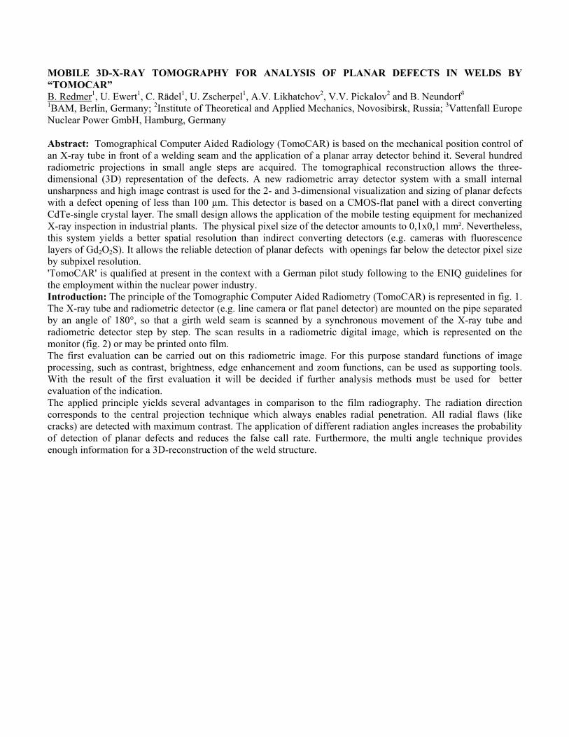
MOBILE 3D-X-RAY TOMOGRAPHY FOR ANALYSIS OF PLANAR DEFECTS IN WELDS BY “TOMOCAR” B. Redmer1, U. Ewert1, C. Rädel1, U. Zscherpel1, A.V. Likhatchov2, V.V. Pickalov2 and B. Neundorf3
1BAM, Berlin, Germany; 2Institute of Theoretical and Applied Mechanics, Novosibirsk, Russia; 3Vattenfall Europe Nuclear Power GmbH, Hamburg, Germany Abstract: Tomographical Computer Aided Radiology (TomoCAR) is based on the mechanical position control of an X-ray tube in front of a welding seam and the application of a planar array detector behind it. Several hundred radiometric projections in small angle steps are acquired. The tomographical reconstruction allows the three-dimensional (3D) representation of the defects. A new radiometric array detector system with a small internal unsharpness and high image contrast is used for the 2- and 3-dimensional visualization and sizing of planar defects with a defect opening of less than 100 µm. This detector is based on a CMOS-flat panel with a direct converting CdTe-single crystal layer. The small design allows the application of the mobile testing equipment for mechanized X-ray inspection in industrial plants. The physical pixel size of the detector amounts to 0,1x0,1 mm². Nevertheless, this system yields a better spatial resolution than indirect converting detectors (e.g. cameras with fluorescence layers of Gd2O2S). It allows the reliable detection of planar defects with openings far below the detector pixel size by subpixel resolution. 'TomoCAR' is qualified at present in the context with a German pilot study following to the ENIQ guidelines for the employment within the nuclear power industry. Introduction: The principle of the Tomographic Computer Aided Radiometry (TomoCAR) is represented in fig. 1. The X-ray tube and radiometric detector (e.g. line camera or flat panel detector) are mounted on the pipe separated by an angle of 180°, so that a girth weld seam is scanned by a synchronous movement of the X-ray tube and radiometric detector step by step. The scan results in a radiometric digital image, which is represented on the monitor (fig. 2) or may be printed onto film. The first evaluation can be carried out on this radiometric image. For this purpose standard functions of image processing, such as contrast, brightness, edge enhancement and zoom functions, can be used as supporting tools. With the result of the first evaluation it will be decided if further analysis methods must be used for better evaluation of the indication. The applied principle yields several advantages in comparison to the film radiography. The radiation direction corresponds to the central projection technique which always enables radial penetration. All radial flaws (like cracks) are detected with maximum contrast. The application of different radiation angles increases the probability of detection of planar defects and reduces the false call rate. Furthermore, the multi angle technique provides enough information for a 3D-reconstruction of the weld structure.
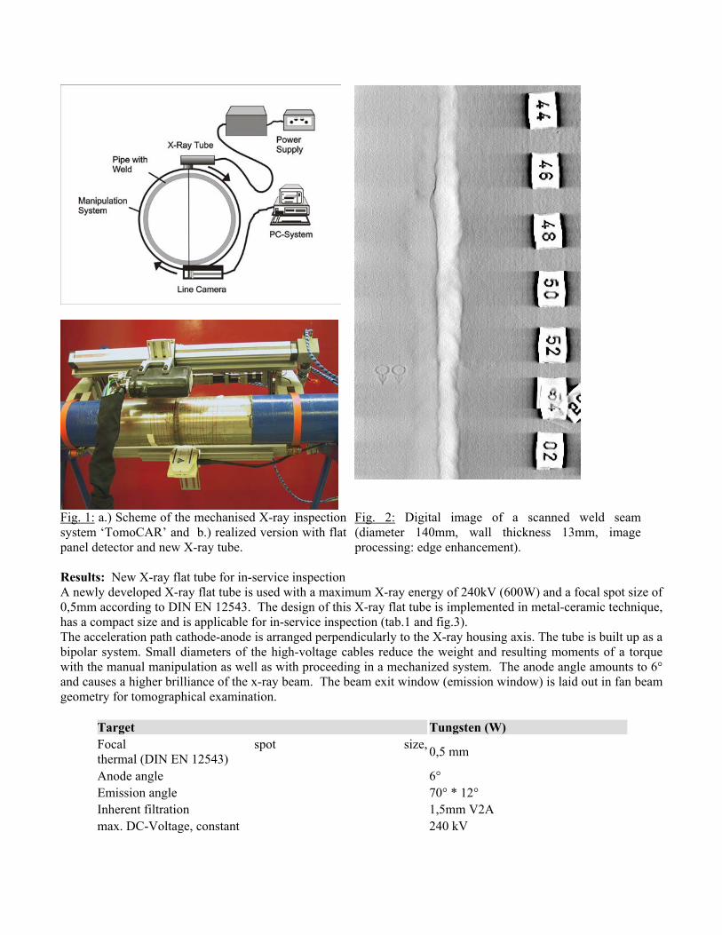
Fig. 1: a.) Scheme of the mechanised X-ray inspection system ‘TomoCAR’ and b.) realized version with flat panel detector and new X-ray tube.
Fig. 2: Digital image of a scanned weld seam (diameter 140mm, wall thickness 13mm, image processing: edge enhancement).
Results: New X-ray flat tube for in-service inspection A newly developed X-ray flat tube is used with a maximum X-ray energy of 240kV (600W) and a focal spot size of 0,5mm according to DIN EN 12543. The design of this X-ray flat tube is implemented in metal-ceramic technique, has a compact size and is applicable for in-service inspection (tab.1 and fig.3). The acceleration path cathode-anode is arranged perpendicularly to the X-ray housing axis. The tube is built up as a bipolar system. Small diameters of the high-voltage cables reduce the weight and resulting moments of a torque with the manual manipulation as well as with proceeding in a mechanized system. The anode angle amounts to 6° and causes a higher brilliance of the x-ray beam. The beam exit window (emission window) is laid out in fan beam geometry for tomographical examination.
Target Tungsten (W) Focal spot size,thermal (DIN EN 12543) 0,5 mm
Anode angle 6° Emission angle 70° * 12° Inherent filtration 1,5mm V2A max. DC-Voltage, constant 240 kV
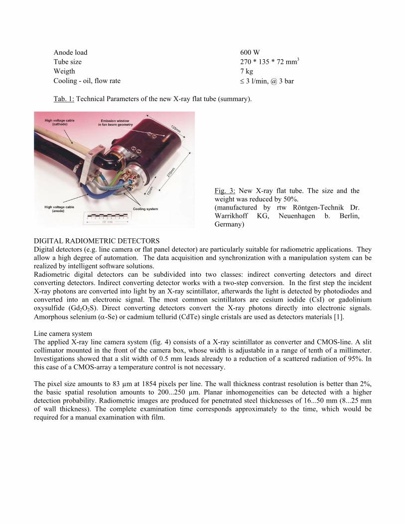
Anode load 600 W Tube size 270 * 135 * 72 mm3 Weigth 7 kg Cooling - oil, flow rate ≤ 3 l/min, @ 3 bar Tab. 1: Technical Parameters of the new X-ray flat tube (summary).
Fig. 3: New X-ray flat tube. The size and the weight was reduced by 50%. (manufactured by rtw Röntgen-Technik Dr. Warrikhoff KG, Neuenhagen b. Berlin, Germany)
DIGITAL RADIOMETRIC DETECTORS Digital detectors (e.g. line camera or flat panel detector) are particularly suitable for radiometric applications. They allow a high degree of automation. The data acquisition and synchronization with a manipulation system can be realized by intelligent software solutions. Radiometric digital detectors can be subdivided into two classes: indirect converting detectors and direct converting detectors. Indirect converting detector works with a two-step conversion. In the first step the incident X-ray photons are converted into light by an X-ray scintillator, afterwards the light is detected by photodiodes and converted into an electronic signal. The most common scintillators are cesium iodide (CsI) or gadolinium oxysulfide (Gd2O2S). Direct converting detectors convert the X-ray photons directly into electronic signals. Amorphous selenium (α-Se) or cadmium tellurid (CdTe) single cristals are used as detectors materials [1]. Line camera system The applied X-ray line camera system (fig. 4) consists of a X-ray scintillator as converter and CMOS-line. A slit collimator mounted in the front of the camera box, whose width is adjustable in a range of tenth of a millimeter. Investigations showed that a slit width of 0.5 mm leads already to a reduction of a scattered radiation of 95%. In this case of a CMOS-array a temperature control is not necessary. The pixel size amounts to 83 µm at 1854 pixels per line. The wall thickness contrast resolution is better than 2%, the basic spatial resolution amounts to 200...250 µm. Planar inhomogeneities can be detected with a higher detection probability. Radiometric images are produced for penetrated steel thicknesses of 16...50 mm (8...25 mm of wall thickness). The complete examination time corresponds approximately to the time, which would be required for a manual examination with film.
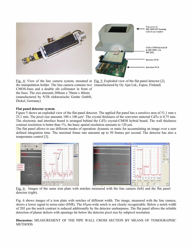
Fig. 4: View of the line camera system, mounted in the manipulation holder. The line camera contains two CMOS-lines and a double slit collimator in front of the lines. The size amounts 200mm x 70mm x 40mm. (manufactured by NTB elektronische Geräte GmbH, Dickel, Germany)
Fig. 5: Exploded view of the flat panel detector [2]. (manufactured by Oy Ajat Ltd., Espoo, Finland)
Flat panel detector system Figure 5 shows an exploded view of the flat panel detector. The applied flat panel has a sensitive area of 51,1 mm x 25,1 mm. The pixel size amounts 100 x 100 µm². The crystal thickness of the converter material CdTe is 0,75 mm. The electronic and interface board is arranged behind the CdTe crystal-CMOS hybrid board. The wall thickness contrast resolution is better than 1%, the basic spatial resolution amounts to 120 µm. The flat panel allows to use different modes of operation: dynamic or static for accumulating an image over a user defined integration time. The maximal frame rate amounts up to 50 frames per second. The detector has also a temperature control [3].
Fig. 6: Images of the same iron plate with notches measured with the line camera (left) and the flat panel detector (right). Fig. 6 shows images of a iron plate with notches of different width. The image, measured with the line camera, shows a lower signal to noise-ratio (SNR). The 65µm-wide notch is not clearly recognizable. Below a notch width of 205 µm the notch contrast is reduced additionally by the detector unsharpness. The flat panel allows the reliable detection of planar defects with openings far below the detector pixel size by subpixel resolution. Discussion: MEASUREMENT OF THE PIPE WALL CROSS SECTION BY MEANS OF TOMOGRAPHIC METHODS
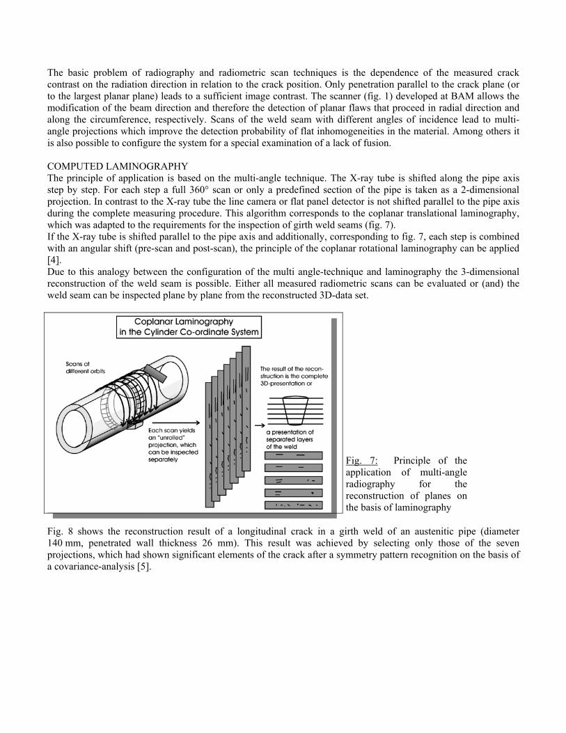
The basic problem of radiography and radiometric scan techniques is the dependence of the measured crack contrast on the radiation direction in relation to the crack position. Only penetration parallel to the crack plane (or to the largest planar plane) leads to a sufficient image contrast. The scanner (fig. 1) developed at BAM allows the modification of the beam direction and therefore the detection of planar flaws that proceed in radial direction and along the circumference, respectively. Scans of the weld seam with different angles of incidence lead to multi-angle projections which improve the detection probability of flat inhomogeneities in the material. Among others it is also possible to configure the system for a special examination of a lack of fusion. COMPUTED LAMINOGRAPHY The principle of application is based on the multi-angle technique. The X-ray tube is shifted along the pipe axis step by step. For each step a full 360° scan or only a predefined section of the pipe is taken as a 2-dimensional projection. In contrast to the X-ray tube the line camera or flat panel detector is not shifted parallel to the pipe axis during the complete measuring procedure. This algorithm corresponds to the coplanar translational laminography, which was adapted to the requirements for the inspection of girth weld seams (fig. 7). If the X-ray tube is shifted parallel to the pipe axis and additionally, corresponding to fig. 7, each step is combined with an angular shift (pre-scan and post-scan), the principle of the coplanar rotational laminography can be applied [4]. Due to this analogy between the configuration of the multi angle-technique and laminography the 3-dimensional reconstruction of the weld seam is possible. Either all measured radiometric scans can be evaluated or (and) the weld seam can be inspected plane by plane from the reconstructed 3D-data set.
Fig. 7: Principle of the application of multi-angle radiography for the reconstruction of planes on the basis of laminography
Fig. 8 shows the reconstruction result of a longitudinal crack in a girth weld of an austenitic pipe (diameter 140 mm, penetrated wall thickness 26 mm). This result was achieved by selecting only those of the seven projections, which had shown significant elements of the crack after a symmetry pattern recognition on the basis of a covariance-analysis [5].
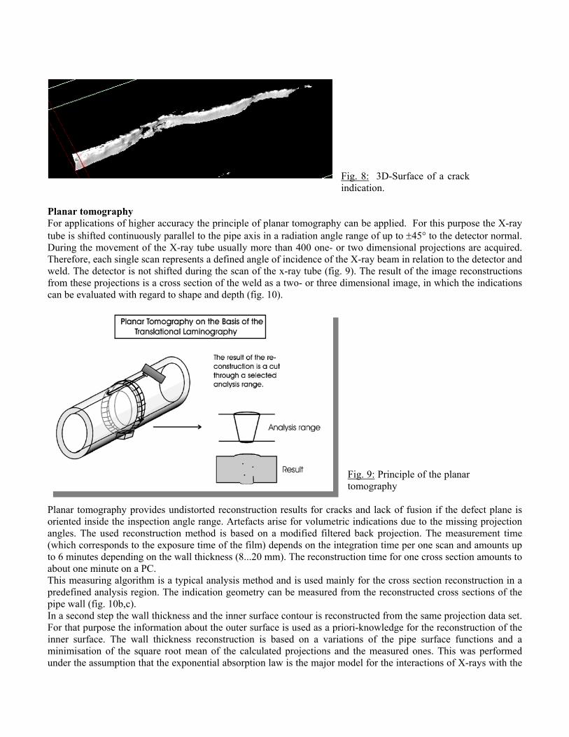
Fig. 8: 3D-Surface of a crack indication.
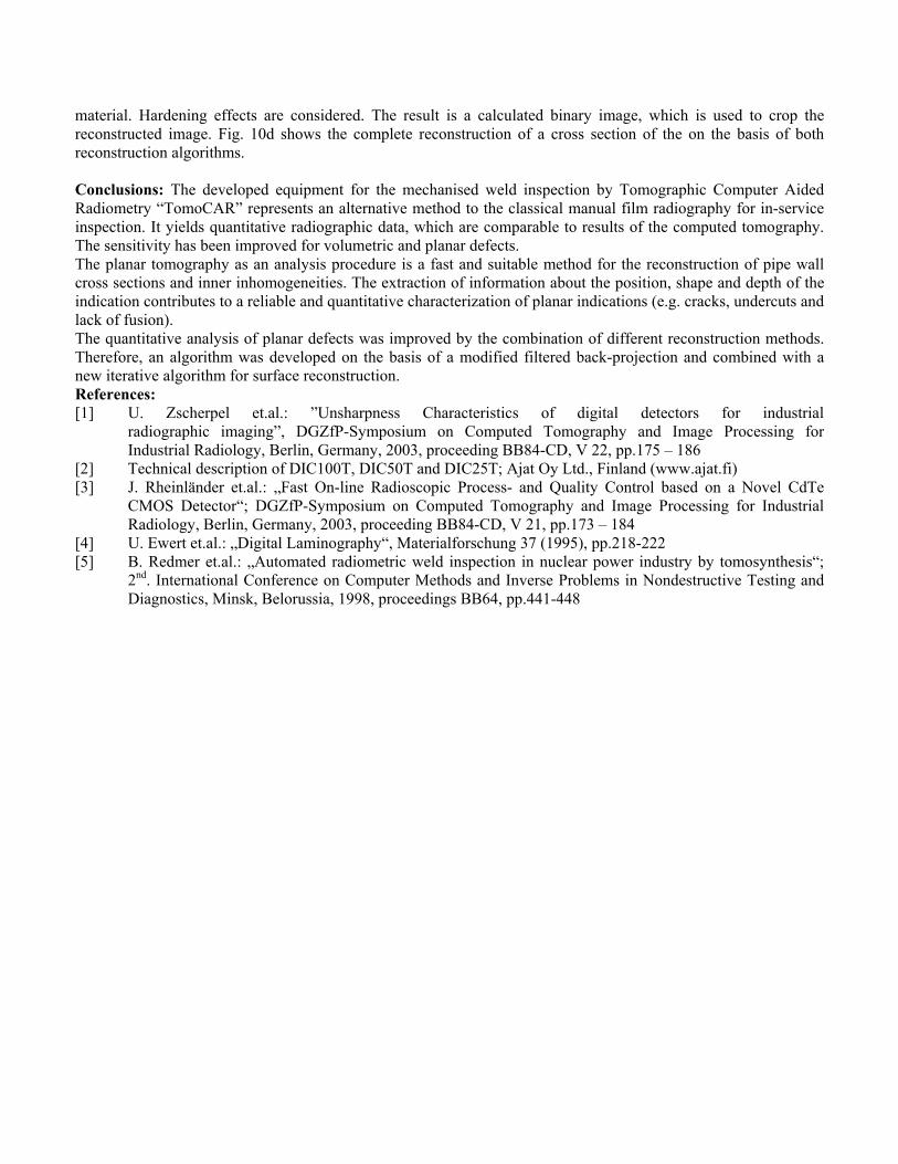
Planar tomography For applications of higher accuracy the principle of planar tomography can be applied. For this purpose the X-ray tube is shifted continuously parallel to the pipe axis in a radiation angle range of up to ±45° to the detector normal. During the movement of the X-ray tube usually more than 400 one- or two dimensional projections are acquired. Therefore, each single scan represents a defined angle of incidence of the X-ray beam in relation to the detector and weld. The detector is not shifted during the scan of the x-ray tube (fig. 9). The result of the image reconstructions from these projections is a cross section of the weld as a two- or three dimensional image, in which the indications can be evaluated with regard to shape and depth (fig. 10).
Fig. 9: Principle of the planar tomography
Planar tomography provides undistorted reconstruction results for cracks and lack of fusion if the defect plane is oriented inside the inspection angle range. Artefacts arise for volumetric indications due to the missing projection angles. The used reconstruction method is based on a modified filtered back projection. The measurement time (which corresponds to the exposure time of the film) depends on the integration time per one scan and amounts up to 6 minutes depending on the wall thickness (8...20 mm). The reconstruction time for one cross section amounts to about one minute on a PC. This measuring algorithm is a typical analysis method and is used mainly for the cross section reconstruction in a predefined analysis region. The indication geometry can be measured from the reconstructed cross sections of the pipe wall (fig. 10b,c). In a second step the wall thickness and the inner surface contour is reconstructed from the same projection data set. For that purpose the information about the outer surface is used as a priori-knowledge for the reconstruction of the inner surface. The wall thickness reconstruction is based on a variations of the pipe surface functions and a minimisation of the square root mean of the calculated projections and the measured ones. This was performed under the assumption that the exponential absorption law is the major model for the interactions of X-rays with the
material. Hardening effects are considered. The result is a calculated binary image, which is used to crop the reconstructed image. Fig. 10d shows the complete reconstruction of a cross section of the on the basis of both reconstruction algorithms. Conclusions: The developed equipment for the mechanised weld inspection by Tomographic Computer Aided Radiometry “TomoCAR” represents an alternative method to the classical manual film radiography for in-service inspection. It yields quantitative radiographic data, which are comparable to results of the computed tomography. The sensitivity has been improved for volumetric and planar defects. The planar tomography as an analysis procedure is a fast and suitable method for the reconstruction of pipe wall cross sections and inner inhomogeneities. The extraction of information about the position, shape and depth of the indication contributes to a reliable and quantitative characterization of planar indications (e.g. cracks, undercuts and lack of fusion). The quantitative analysis of planar defects was improved by the combination of different reconstruction methods. Therefore, an algorithm was developed on the basis of a modified filtered back-projection and combined with a new iterative algorithm for surface reconstruction. References: [1] U. Zscherpel et.al.: ”Unsharpness Characteristics of digital detectors for industrial
radiographic imaging”, DGZfP-Symposium on Computed Tomography and Image Processing for Industrial Radiology, Berlin, Germany, 2003, proceeding BB84-CD, V 22, pp.175 – 186
[2] Technical description of DIC100T, DIC50T and DIC25T; Ajat Oy Ltd., Finland (www.ajat.fi) [3] J. Rheinländer et.al.: „Fast On-line Radioscopic Process- and Quality Control based on a Novel CdTe
CMOS Detector“; DGZfP-Symposium on Computed Tomography and Image Processing for Industrial Radiology, Berlin, Germany, 2003, proceeding BB84-CD, V 21, pp.173 – 184
[4] U. Ewert et.al.: „Digital Laminography“, Materialforschung 37 (1995), pp.218-222 [5] B. Redmer et.al.: „Automated radiometric weld inspection in nuclear power industry by tomosynthesis“;
2nd. International Conference on Computer Methods and Inverse Problems in Nondestructive Testing and Diagnostics, Minsk, Belorussia, 1998, proceedings BB64, pp.441-448
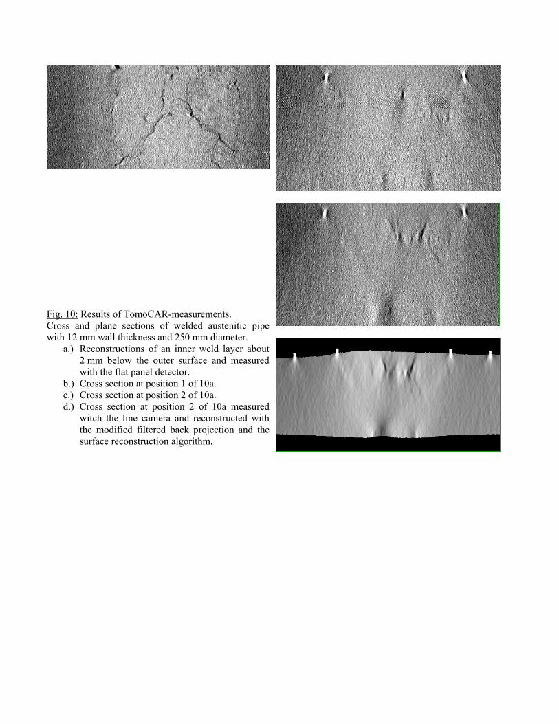
Fig. 10: Results of TomoCAR-measurements. Cross and plane sections of welded austenitic pipe with 12 mm wall thickness and 250 mm diameter.
a.) Reconstructions of an inner weld layer about 2 mm below the outer surface and measured with the flat panel detector.
b.) Cross section at position 1 of 10a. c.) Cross section at position 2 of 10a. d.) Cross section at position 2 of 10a measured
witch the line camera and reconstructed with the modified filtered back projection and the surface reconstruction algorithm.