Embed Size (px)
Citation preview
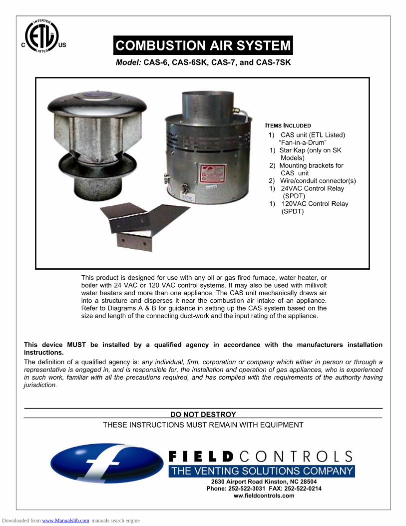
COMBUSTION AIR SYSTEM Model: CAS-6, CAS-6SK, CAS-7, and CAS-7SK
This product is designed for use with any oil or gas fired furnace, water heater, or boiler with 24 VAC or 120 VAC control systems. It may also be used with millivolt water heaters and more than one appliance. The CAS unit mechanically draws air into a structure and disperses it near the combustion air intake of an appliance. Refer to Diagrams A & B for guidance in setting up the CAS system based on the size and length of the connecting duct-work and the input rating of the appliance.
This device MUST be installed by a qualified agency in accordance with the manufacturers installation instructions. The definition of a qualified agency is: any individual, firm, corporation or company which either in person or through a representative is engaged in, and is responsible for, the installation and operation of gas appliances, who is experienced in such work, familiar with all the precautions required, and has complied with the requirements of the authority having jurisdiction.
DO NOT DESTROY THESE INSTRUCTIONS MUST REMAIN WITH EQUIPMENT
ITEMS INCLUDED 1) CAS unit (ETL Listed)
“Fan-in-a-Drum” 1) Star Kap (only on SK
Models) 2) Mounting brackets for
CAS unit 2) Wire/conduit connector(s)
1) 24VAC Control Relay (SPDT)
1) 120VAC Control Relay (SPDT)
2630 Airport Road Kinston, NC 28504 Phone: 252-522-3031 FAX: 252-522-0214
ww.fieldcontrols.com
Downloaded from www.Manualslib.com manuals search engine
GENERAL SYSTEM OPERATION 1. The thermostat (wall thermostat, or aquastat) calls for heat and energizes a relay which activates the CAS unit. After
the CAS fan has come up to speed, an internal air pressure switch closes and completes the circuit to allow the burner to fire. If the appliance is power vented, the venter and will typically activate before the CAS unit..
2. After the heating requirement has been satisfied, the thermostat circuit will open and deactivate the burner and CAS unit.
3. For power vented systems with a post purge device, the power venter will operate for a period of time determined by the post purge timer setting after the burner has shut off to purge remaining flue gases from the vent system.
INSTALLATION SAFETY INSTRUCTIONS CAUTION: This device must be installed by a qualified installer in accordance with the manufacturer's installation instructions. 1. This combustion air system must be installed by a qualified installer. "Qualified Installer" shall mean an individual who
has been properly trained or a licensed installer. 2. Plan the system layout before installation to avoid the possibility of accidental contact with concealed wiring or
plumbing inside walls. 3. Disconnect power supply before making wiring connections to prevent electrical shock and equipment damage. SIZING AND SETUP Diagram A shows the maximum equivalent length and size of duct pipe that should be used when installing the CAS-6 system; Diagram B shows the same for the CAS-7. Using this table will help ensure that the proper amount of air is drawn into the structure as needed by the appliance. The defined regions shown correspond to the CAS's airflow characteristics when using various sizes of duct pipe for the CAS-6 and CAS-7. Follow the guidelines below to properly size and set up the CAS system. 1. Determine the input firing rate of the appliance, or the total firing rate of multiple appliances that will be used. 2. Determine the location of the CAS unit according to the guidelines in the "Installation" section. 3. Determine where the intake air StarKap will be located based on the recommendations in the "Installation" section. 4. On Diagram A or B (as appropriate), locate the point that corresponds to the firing rate along the horizontal axis and
draw a vertical line through this point. 5. The line should pass through at least one of the pipe size regions on the table. The regions correspond to the
maximum equivalent lengths of the given diameter duct pipe that will be adequately sized for the application. 6. Calculate the equivalent length of the smaller diameter duct pipe that may be used with the particular CAS system,
including elbows, reducer/increaser and other fittings (except the StarKap, see page 32 of the Field Controls Contractor Reference Guide). The effects of the StarKap are already figured into the diagram, so do not attempt to include any value for the StarKap in your calculation for equivalent length. Draw a horizontal line through the point corresponding to the equivalent length on the vertical axis.
7. Locate the intersection of the two drawn lines. If the intersection lies in the region for the equivalent length of pipe for which the equivalent length was calculated, then that diameter of duct pipe will be of sufficient size for the application. If not, then repeat step 7 using a larger diameter duct, then proceed to step 9.
8. If the intersection of the two lines falls into the larger duct region, then that diameter duct will be of sufficient size for the application. If it falls to the right of the larger pipe region, then even larger pipe or additional CAS units will be required for the application. For assistance in this case, call Field Controls Technical Support at 1-800-742-8368.
Example: An oil fired appliance firing at 10.5 gph where a CAS-7 unit needs to be placed at a location requiring 80 feet of pipe from the StarKap, using two 90 degree elbows: From Diagram B, a vertical line is drawn through the point at 10.5 gph on the "Oil Firing Rate" scale. For 80 feet of 10” pipe, two 90 degree elbows, and two increaser/ reducers, the equivalent length is 80 + 18 + 18 + 6 + 6 = 128 feet of equivalent length. A horizontal line drawn through the point at 128 feet on the “Equivalent Length” scale intersects the vertical line in the 12” duct region of the diagram. Since the intersection is not in the 10” duct region, recalculate the equivalent length using 12” duct: 80 + 21 + 21 + 7 + 7 = 136 feet of equivalent length. A horizontal line drawn through the 136 point on the “Equivalent Length” scale intersects the vertical line within the 12” duct region of the diagram; therefore, 12” duct will be of sufficient size for the application.
Page 2
Downloaded from www.Manualslib.com manuals search engine
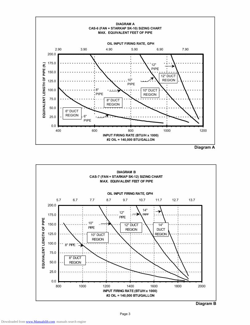
DIAGRAM ACAS-6 (FAN + STARKAP SK-10) SIZING CHART
MAX. EQUIVALENT FEET OF PIPE
0.0
25.0
50.0
75.0
100.0
125.0
150.0
175.0
200.0
400 600 800 1000 1200INPUT FIRING RATE (BTU/H x 1000)
#2 OIL = 140,000 BTU/GALLON
EQU
IVA
LEN
T LE
NG
TH O
F PI
PE (f
t.)2.90 3.90 4.90 5.90 6.90 7.90
OIL INPUT FIRING RATE, GPH
12" PIPE
10" PIPE
6" PIPE
8" PIPE
6" DUCT REGION
8" DUCT REGION
10" DUCT REGION
12" DUCT REGION
Diagram A
DIAGRAM BCAS-7 (FAN + STARKAP SK-12) SIZING CHART
MAX. EQUIVALENT FEET OF PIPE
0.0
25.0
50.0
75.0
100.0
125.0
150.0
175.0
200.0
800 1000 1200 1400 1600 1800 2000INPUT FIRING RATE (BTU/H x 1000)
#2 OIL = 140,000 BTU/GALLON
EQU
IVA
LEN
T LE
NG
TH O
F PI
PE
5.7 6.7 7.7 8.7 9.7 10.7 11.7 12.7 13.7
OIL INPUT FIRING RATE, GPH
12" PIPE
10" PIPE
8" PIPE
14" PIPE
8" DUCT REGION
10" DUCT REGION
12" DUCT REGION
14" DUCT
REGION
Diagram B
Page 3
Downloaded from www.Manualslib.com manuals search engine
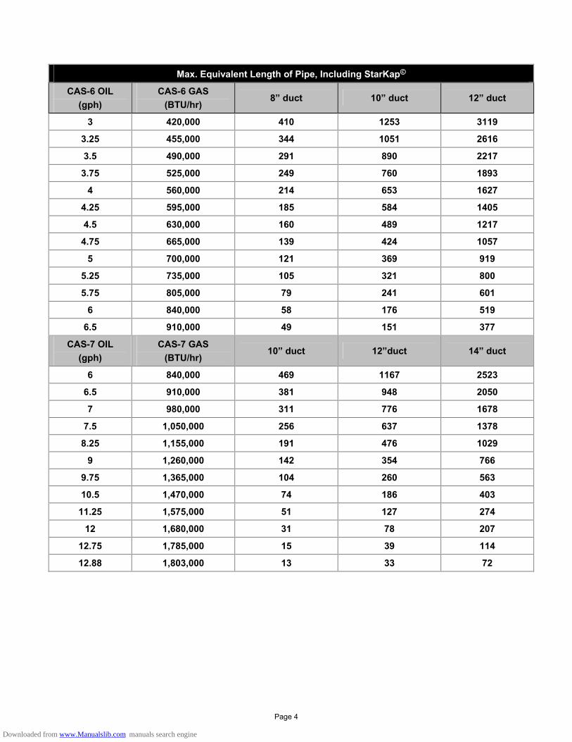
Max. Equivalent Length of Pipe, Including StarKap©
CAS-6 OIL (gph)
CAS-6 GAS (BTU/hr)
8” duct 10” duct 12” duct
3 420,000 410 1253 3119
3.25 455,000 344 1051 2616
3.5 490,000 291 890 2217
3.75 525,000 249 760 1893
4 560,000 214 653 1627
4.25 595,000 185 584 1405
4.5 630,000 160 489 1217
4.75 665,000 139 424 1057
5 700,000 121 369 919
5.25 735,000 105 321 800
5.75 805,000 79 241 601
6 840,000 58 176 519
6.5 910,000 49 151 377
CAS-7 OIL (gph)
CAS-7 GAS (BTU/hr)
10” duct 12”duct 14” duct
6 840,000 469 1167 2523
6.5 910,000 381 948 2050
7 980,000 311 776 1678
7.5 1,050,000 256 637 1378
8.25 1,155,000 191 476 1029
9 1,260,000 142 354 766
9.75 1,365,000 104 260 563
10.5 1,470,000 74 186 403
11.25 1,575,000 51 127 274
12 1,680,000 31 78 207
12.75 1,785,000 15 39 114
12.88 1,803,000 13 33 72
Page 4
Downloaded from www.Manualslib.com manuals search engine

Figure 1
INSTALLATION PLACEMENT OF THE CAS UNIT The motorized CAS unit should be located on a flat horizontal surface near the combustion air intake of the appliance. Two mounting brackets are provided for securing the unit against a solid structure, such as a wall, column, or the side of the appliance itself. Use the included screws to attach the brackets to the CAS housing as shown in Figure 1. Secure the brackets to a solid structure with appropriate fasteners. It is not required to use the brackets as long as the unit is located so that it may not be bumped, moved, or tipped over. INTAKE AIR STARKAP LOCATION The StarKap should be located on an outside wall or roof maintaining clearances to other intake and exhaust vents in accordance with the National Fuel Gas Code, ANSI Z223.1, manufacturer's recommendations and/ors local codes which are applicable. The StarKap should be located at least 10 feet from a building exhaust outlet, equipment vent, or chimney termination.
Figure 2
INSTALLATION OF INTAKE AIR STARKAP After determining the location of the StarKap, cut an appropriately sized hole in the wall or roof, taking precautions to avoid interference with wiring or other plumbing in the structure to be cut. Pre-attach a short length of duct to the StarKap if necessary. Insert the StarKap and secure with appropriate fasteners. Flash in the opening in accordance with local building codes. INSTALLATION OF DUCT Refer to Diagram A or B to determine what size pipe is needed. Connect the duct pipe from the top of the CAS unit to the StarKap. If using pipe of different diameter than the CAS component connections, attach increaser/reducer fittings as close to the CAS unit and to the StarKap as possible. The duct should be supported with appropriate mounting straps from floor joists, walls, or other solid structures. The straps should be placed so as to keep the duct work out of passageways (See Figure 2). For best performance, install elbows or tees no closer than 3 pipe diameters from the inlet of the CAS unit.
Figure 3
WIRING Wire the CAS unit in accordance with the National Electric Code and applicable local codes. UNIT MUST BE GROUNDED. Check the ground circuit to make certain that the unit has been properly grounded. The wiring should be protected by an over-current circuit device rated at 20 amperes. CAUTION must be taken to ensure that the wiring does not come in contact with any heat source. All line voltage and control circuits between the CAS unit and the appliance MUST be wired in accordance with the National Electrical Code for Class I wiring or higher, according to the installation environment. 1. Remove the wiring access cover to access the wiring
terminals. 2. Select the appropriate control relay for the appliance control system voltage from the two relays supplied with the
CAS system (see illustration) Use the 24VAC relay for a 24V control system (typical gas-fired), or the 120VAC relay for a 120V control system (typical oil-fired). Install the selected relay into the socket provided on the wiring panel, and secure with the wire retaining clip.
3. Use the enclosed conduit connectors or like connectors to route the appropriate wires through the CAS housing. The incoming ground wire must be attached to the green grounding screw located near the wire terminals. The following
Page 5
Downloaded from www.Manualslib.com manuals search engine
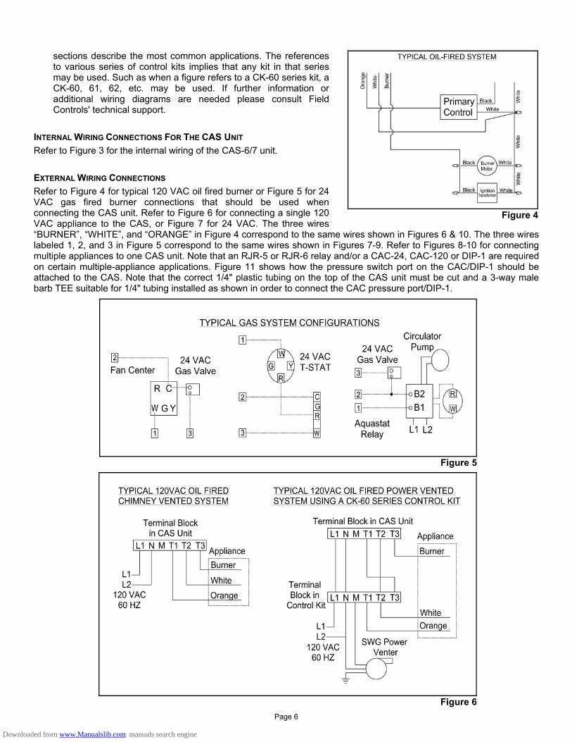
sections describe the most common applications. The references to various series of control kits implies that any kit in that series may be used. Such as when a figure refers to a CK-60 series kit, a CK-60, 61, 62, etc. may be used. If further information or additional wiring diagrams are needed please consult Field Controls' technical support.
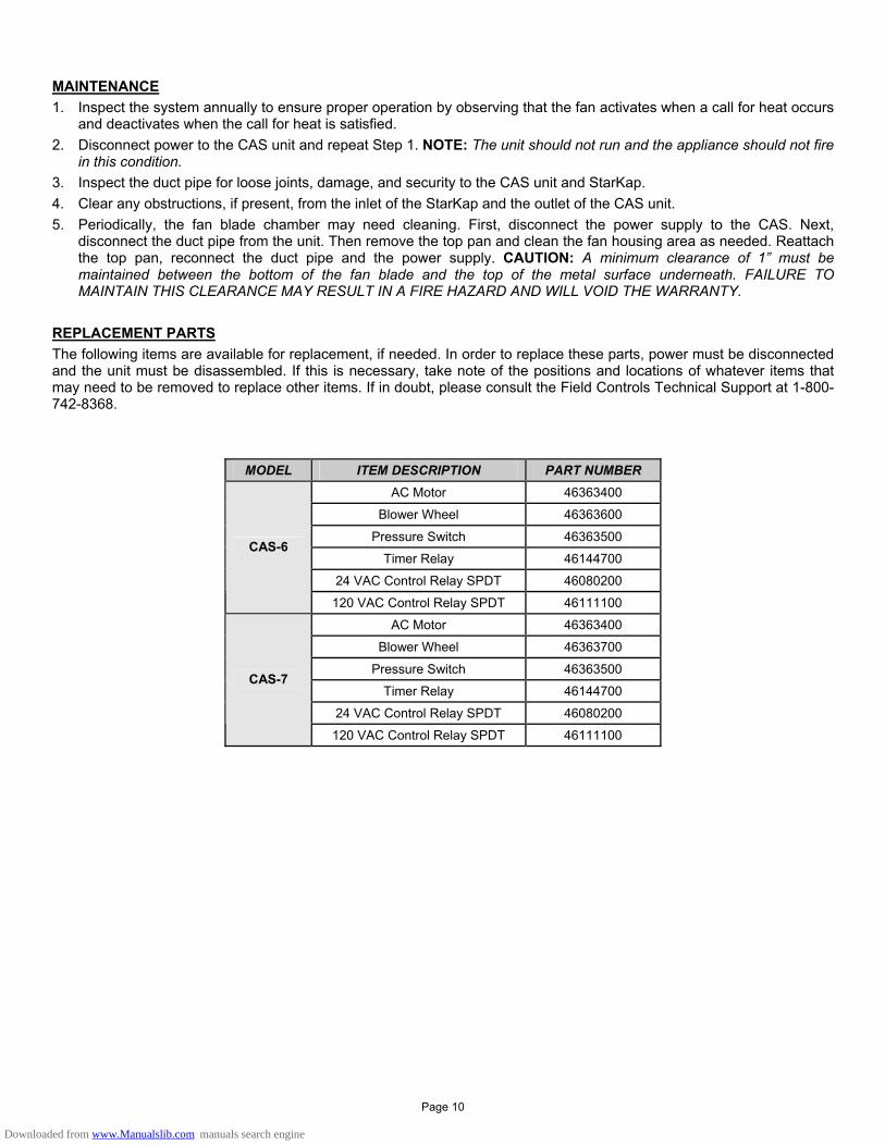
INTERNAL WIRING CONNECTIONS FOR THE CAS UNIT Refer to Figure 3 for the internal wiring of the CAS-6/7 unit. EXTERNAL WIRING CONNECTIONS Refer to Figure 4 for typical 120 VAC oil fired burner or Figure 5 for 24 VAC gas fired burner connections that should be used when connecting the CAS unit. Refer to Figure 6 for connecting a single 120 VAC appliance to the CAS, or Figure 7 for 24 VAC. The three wires “BURNER”, “WHITE”, and “ORANGE” in Figure 4 correspond to the same wires shown in Figures 6 & 10. The three wires labeled 1, 2, and 3 in Figure 5 correspond to the same wires shown in Figures 7-9. Refer to Figures 8-10 for connecting multiple appliances to one CAS unit. Note that an RJR-5 or RJR-6 relay and/or a CAC-24, CAC-120 or DIP-1 are required on certain multiple-appliance applications. Figure 11 shows how the pressure switch port on the CAC/DIP-1 should be attached to the CAS. Note that the correct 1/4" plastic tubing on the top of the CAS unit must be cut and a 3-way male barb TEE suitable for 1/4" tubing installed as shown in order to connect the CAC pressure port/DIP-1.
Figure 4
Figure 5
Figure 6
Page 6
Downloaded from www.Manualslib.com manuals search engine
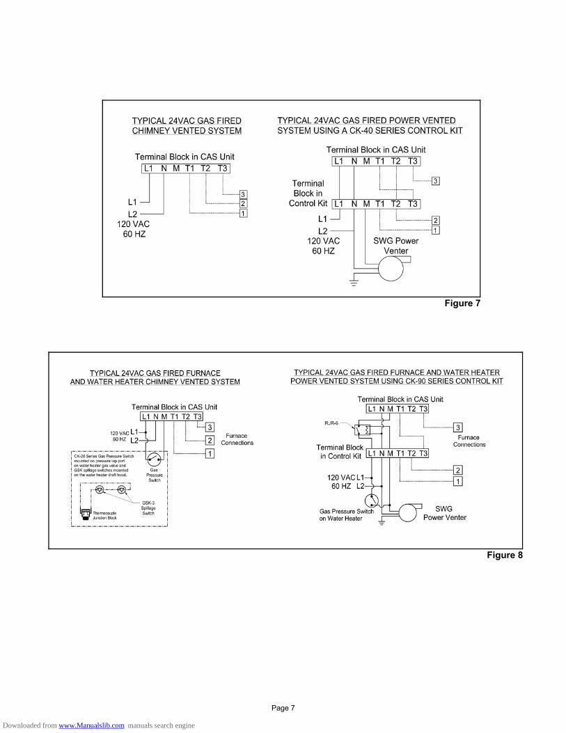
Figure 7
Figure 8
Page 7
Downloaded from www.Manualslib.com manuals search engine
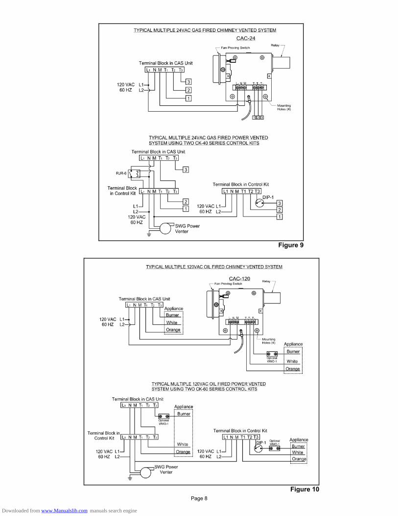
Figure 9
Figure 10 Page 8
Downloaded from www.Manualslib.com manuals search engine
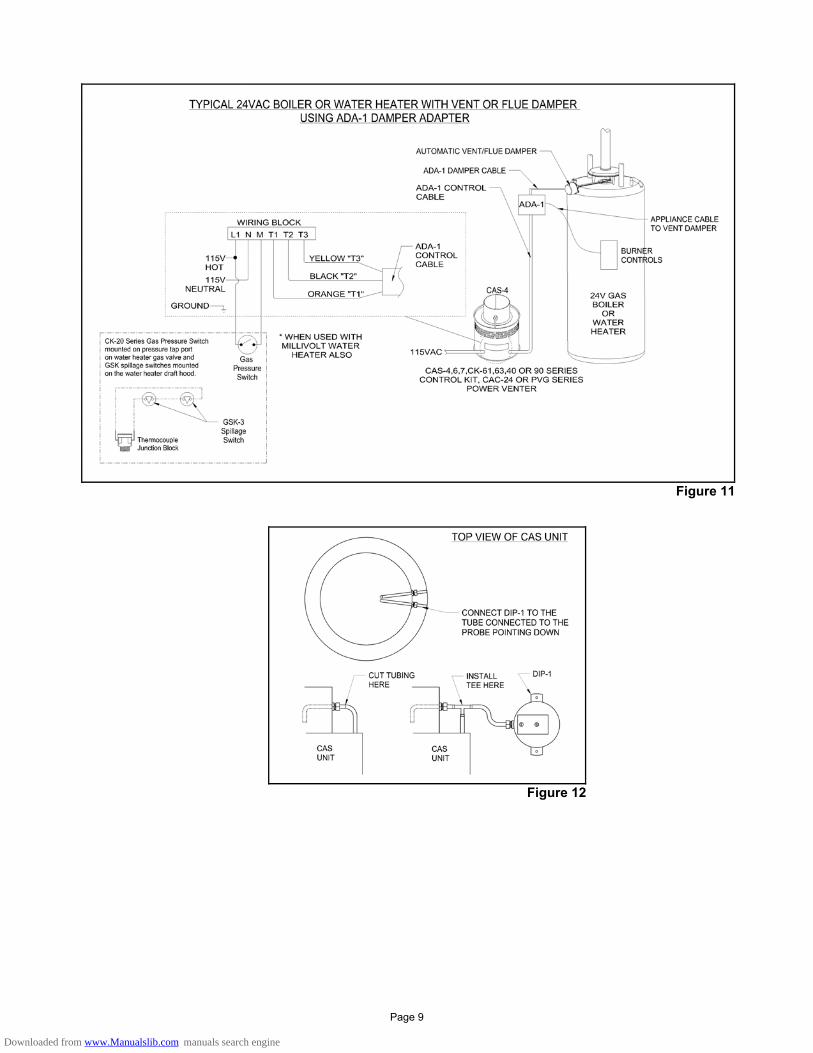
Figure 11
Figure 12
Page 9
Downloaded from www.Manualslib.com manuals search engine
MAINTENANCE 1. Inspect the system annually to ensure proper operation by observing that the fan activates when a call for heat occurs
and deactivates when the call for heat is satisfied. 2. Disconnect power to the CAS unit and repeat Step 1. NOTE: The unit should not run and the appliance should not fire
in this condition. 3. Inspect the duct pipe for loose joints, damage, and security to the CAS unit and StarKap. 4. Clear any obstructions, if present, from the inlet of the StarKap and the outlet of the CAS unit. 5. Periodically, the fan blade chamber may need cleaning. First, disconnect the power supply to the CAS. Next,
disconnect the duct pipe from the unit. Then remove the top pan and clean the fan housing area as needed. Reattach the top pan, reconnect the duct pipe and the power supply. CAUTION: A minimum clearance of 1” must be maintained between the bottom of the fan blade and the top of the metal surface underneath. FAILURE TO MAINTAIN THIS CLEARANCE MAY RESULT IN A FIRE HAZARD AND WILL VOID THE WARRANTY.
REPLACEMENT PARTS The following items are available for replacement, if needed. In order to replace these parts, power must be disconnected and the unit must be disassembled. If this is necessary, take note of the positions and locations of whatever items that may need to be removed to replace other items. If in doubt, please consult the Field Controls Technical Support at 1-800-742-8368.
MODEL ITEM DESCRIPTION PART NUMBER AC Motor 46363400
Blower Wheel 46363600
Pressure Switch 46363500
Timer Relay 46144700
24 VAC Control Relay SPDT 46080200
CAS-6
120 VAC Control Relay SPDT 46111100
AC Motor 46363400
Blower Wheel 46363700
Pressure Switch 46363500
Timer Relay 46144700
24 VAC Control Relay SPDT 46080200
CAS-7
120 VAC Control Relay SPDT 46111100
Page 10
Downloaded from www.Manualslib.com manuals search engine

Page 12 P/N 46371700 Rev B 06/06
Downloaded from www.Manualslib.com manuals search engine