Embed Size (px)
Citation preview
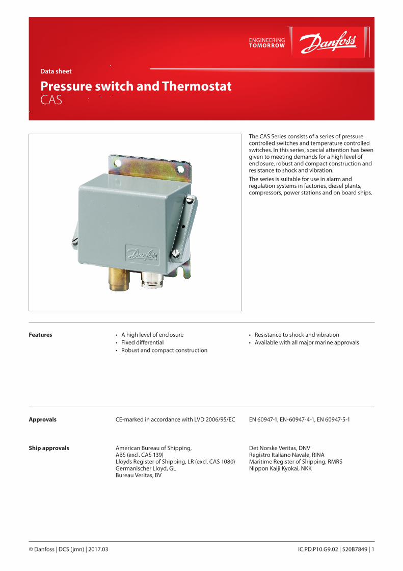
The CAS Series consists of a series of pressure controlled switches and temperature controlled switches. In this series, special attention has been given to meeting demands for a high level of enclosure, robust and compact construction and resistance to shock and vibration. The series is suitable for use in alarm and regulation systems in factories, diesel plants, compressors, power stations and on board ships.
Features
Approvals
Ship approvals
• A high level of enclosure• Fixed differential• Robust and compact construction
• Resistance to shock and vibration• Available with all major marine approvals
Data sheet
Pressure switch and Thermostat CAS
IC.PD.P10.G9.02 | 520B7849 | 1© Danfoss | DCS (jmn) | 2017.03
CE-marked in accordance with LVD 2006/95/EC EN 60947-1, EN-60947-4-1, EN 60947-5-1
American Bureau of Shipping, ABS (excl. CAS 139)Lloyds Register of Shipping, LR (excl. CAS 1080)Germanischer Lloyd, GLBureau Veritas, BV
Det Norske Veritas, DNVRegistro Italiano Navale, RINAMaritime Register of Shipping, RMRSNippon Kaiji Kyokai, NKK
Data sheet | Pressure switch and Thermostat, type CAS
© Danfoss | DCS (jmn) | 2017.032 | 520B7849 | IC.PD.P10.G9.02
[bar]Range Pe
[bar] Type0 10 20 30 40 50 60
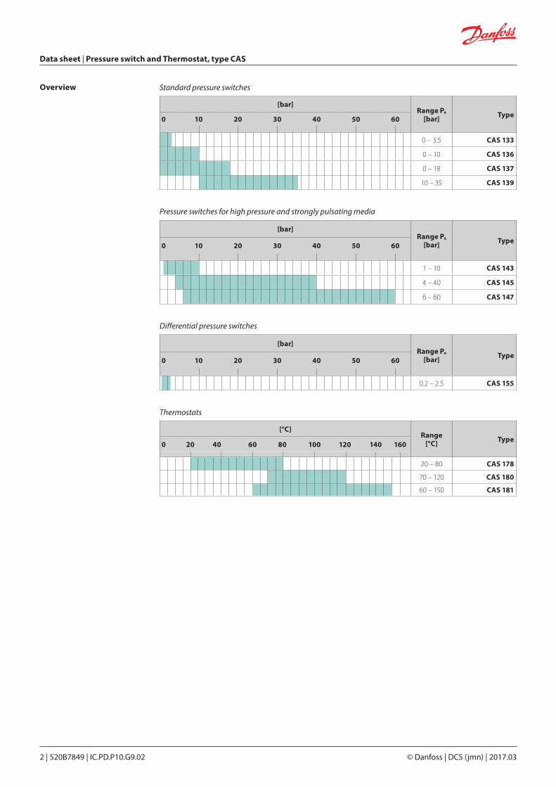
0 – 3.5 CAS 133
0 – 10 CAS 136
0 – 18 CAS 137
10 – 35 CAS 139
Standard pressure switches
[°C]Range
[°C] Type0 20 40 60 80 100 120 140 160
20 – 80 CAS 178
70 – 120 CAS 180
60 – 150 CAS 181
Thermostats
[bar]Range Pe
[bar] Type0 10 20 30 40 50 60
1 – 10 CAS 143
4 – 40 CAS 145
6 – 60 CAS 147
Pressure switches for high pressure and strongly pulsating media
[bar]Range Pe
[bar] Type0 10 20 30 40 50 60
0.2 – 2.5 CAS 155
Differential pressure switches
Overview

© Danfoss | DCS (jmn) | 2017.03 IC.PD.P10.G9.02 | 520B7849 | 3
Data sheet | Pressure switch and Thermostat, type CAS
Technical data Switch Microswitch with single pole changeover (SPDT)
Contact loadAlternating current AC-14 / AC-15: 0.1 A, 220 V
Direct current DC-13: 12 W, 125 V
Ambient temperatureCAS 133 – 139 -40 – 70 °C
CAS 143 – 155 -25 – 70 °C
Temperature of medium1)
CAS 133 – 139 -40 – 100 °C
CAS 143 – 155 -25 – 100 °C
Vibration resistance Vibration-stable in the range 2 – 30 Hz amplitude 1.1 mm and 30 – 100 Hz, 4 g.
Cable entry Pg 13.5 for cable diametrers from 5 – 14 mm. 1) For water and seawater, max. 80 °C
EnclosureIP67 acc. to EN 60529.The pressure control housing is enamelled pressure die cast aluminium (GD-AISi 12). The cover is fastened by four screws which are anchored to prevent loss.The enclosure can be sealed with fuse wire.
IdentificationThe type designation and code no. of the unit is stamped in the side of the housing.
PRESSURE SWITCH
Type Materials
CAS 133, CAS 136, CAS 137, CAS 139
Bellows: Stainless steel, material no. 1.4306 (DIN 17440)
Pressure connection: Brass material no. 2.0401 (DIN 17660)
CAS 143, CAS 145, CAS 147, CAS 155
Diaphragm connection: Nickel plated brass CuZn 40 Ob3 ISO R 426 (DIN 17569)
Diaphragm: Nitrile-butadien rubber
Materials in contact with the medium
Terminology
Data sheet | Pressure switch and Thermostat, type CAS
© Danfoss | DCS (jmn) | 2017.034 | 520B7849 | IC.PD.P10.G9.02
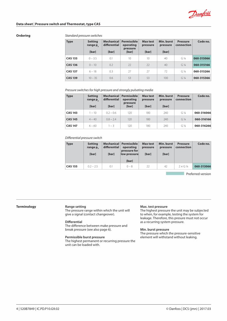
Ordering
Preferred version
Type Setting range pe
[bar]
Mechanical differential
[bar]
Permissible operating pressure
[bar]
Max test pressure
[bar]
Min. burst pressure
[bar]
Pressure connection
Code no.
CAS 133 0 – 3.5 0.1 10 10 40 G ¼ 060-315066
CAS 136 0 – 10 0.2 22 22 40 G ¼ 060-315166
CAS 137 6 – 18 0.3 27 27 72 G ¼ 060-315266
CAS 139 10 – 35 0.6 53 53 100 G ¼ 060-315366
Type Setting range pe
[bar]
Mechanical differential
[bar]
Permissible operating pressure
[bar]
Max test pressure
[bar]
Min. burst pressure
[bar]
Pressure connection
Code no.
CAS 143 1 – 10 0.2 – 0.6 120 180 240 G ¼ 060-316066
CAS 145 4 – 40 0.8 – 2.4 120 180 240 G ¼ 060-316166
CAS 147 6 – 60 1 – 3 120 180 240 G ¼ 060-316266
Type Setting range pe
[bar]
Mechanical differential
[bar]
Permissible operating
pressure forlow pressure
[bar]
Max test pressure
[bar]
Min. burst pressure
[bar]
Pressure connection
Code no.
CAS 155 0.2 – 2.5 0.1 0 – 8 22 42 2 × G ¼ 060-313066
Range settingThe pressure range within which the unit will give a signal (contact changeover).
DifferentialThe difference between make pressure and break pressure (see also page 6).
Permissible burst pressureThe highest permanent or recurring pressure the unit can be loaded with.
Max. test pressureThe highest pressure the unit may be subjected to when, for example, testing the system for leakage. Therefore, this presure must not occur as a recurring system pressure.
Min. burst pressureThe pressure which the pressure-sensitive element will withstand without leaking.
Standard pressure switches
Differential pressure switch
Pressure switches for high pressure and strongly pulsating media
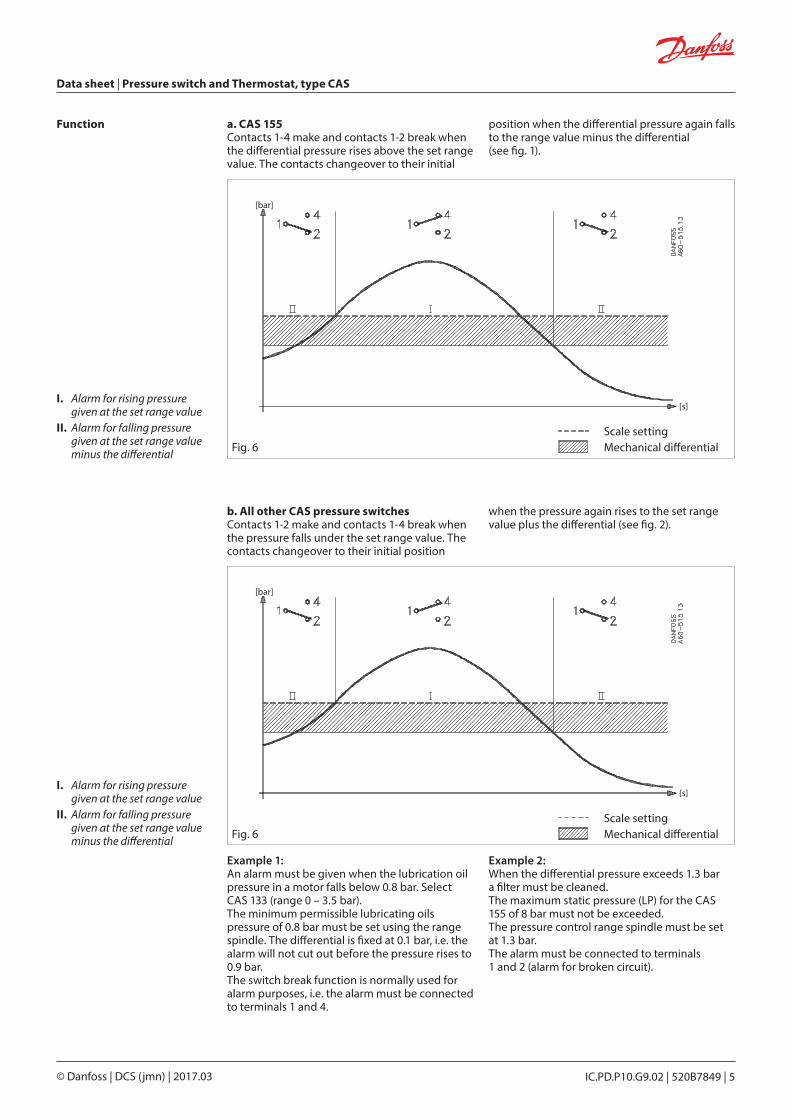
Fig. 6
[bar]
[s]
© Danfoss | DCS (jmn) | 2017.03 IC.PD.P10.G9.02 | 520B7849 | 5
Data sheet | Pressure switch and Thermostat, type CAS
Scale settingMechanical differential
Function a. CAS 155Contacts 1-4 make and contacts 1-2 break when the differential pressure rises above the set range value. The contacts changeover to their initial
position when the differential pressure again falls to the range value minus the differential (see fig. 1).
b. All other CAS pressure switchesContacts 1-2 make and contacts 1-4 break when the pressure falls under the set range value. The contacts changeover to their initial position
when the pressure again rises to the set range value plus the differential (see fig. 2).
Example 1:An alarm must be given when the lubrication oil pressure in a motor falls below 0.8 bar. Select CAS 133 (range 0 – 3.5 bar).The minimum permissible lubricating oils pressure of 0.8 bar must be set using the range spindle. The differential is fixed at 0.1 bar, i.e. the alarm will not cut out before the pressure rises to 0.9 bar. The switch break function is normally used for alarm purposes, i.e. the alarm must be connected to terminals 1 and 4.
Example 2:When the differential pressure exceeds 1.3 bar a filter must be cleaned.The maximum static pressure (LP) for the CAS 155 of 8 bar must not be exceeded.The pressure control range spindle must be set at 1.3 bar.The alarm must be connected to terminals 1 and 2 (alarm for broken circuit).
Scale settingMechanical differentialFig. 6
I. Alarm for rising pressure given at the set range value
II. Alarm for falling pressure given at the set range value minus the differential
I. Alarm for rising pressure given at the set range value
II. Alarm for falling pressure given at the set range value minus the differential
[bar]
[s]
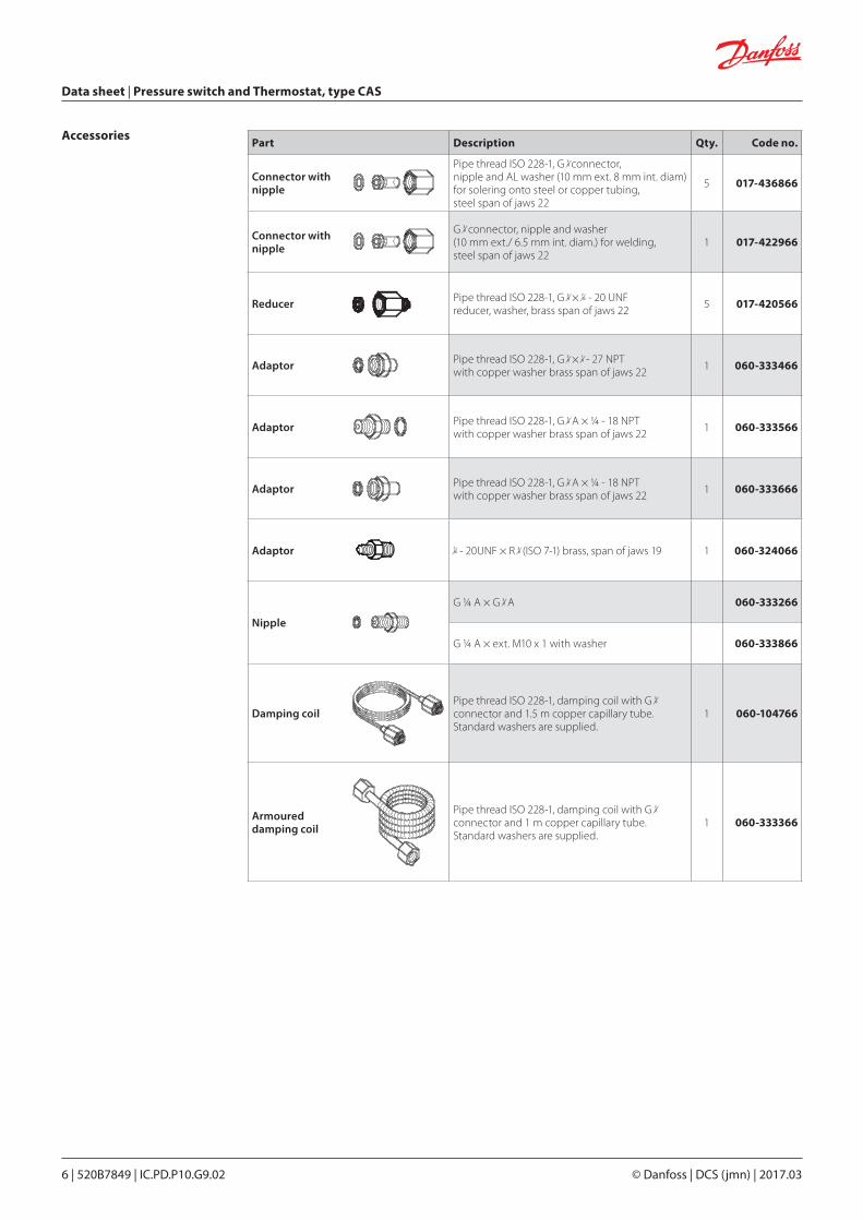
Part Description Qty. Code no.
Connector with nipple
Pipe thread ISO 228-1, G 3/8 connector, nipple and AL washer (10 mm ext. 8 mm int. diam) for solering onto steel or copper tubing, steel span of jaws 22
5 017-436866
Connector with nipple
G 3/8 connector, nipple and washer (10 mm ext./ 6.5 mm int. diam.) for welding, steel span of jaws 22
1 017-422966
Reducer
Dan
foss
17.9
051
Pipe thread ISO 228-1, G 3/8 × 7/16 - 20 UNF reducer, washer, brass span of jaws 22 5 017-420566
Adaptor Pipe thread ISO 228-1, G 3/8 × 1/8 - 27 NPT with copper washer brass span of jaws 22 1 060-333466
Adaptor Pipe thread ISO 228-1, G 3/8 A × ¼ - 18 NPT with copper washer brass span of jaws 22 1 060-333566
Adaptor Pipe thread ISO 228-1, G 3/8 A × ¼ - 18 NPT with copper washer brass span of jaws 22 1 060-333666
Adaptor 7/16 - 20UNF × R 3/8 (ISO 7-1) brass, span of jaws 19 1 060-324066
Nipple
G ¼ A × G 3/8 A 060-333266
G ¼ A × ext. M10 x 1 with washer 060-333866
Damping coil
Dan
foss
60.9
030
Pipe thread ISO 228-1, damping coil with G 3/8 connector and 1.5 m copper capillary tube. Standard washers are supplied.
1 060-104766
Armoured damping coil
Pipe thread ISO 228-1, damping coil with G 3/8 connector and 1 m copper capillary tube. Standard washers are supplied.
1 060-333366
Data sheet | Pressure switch and Thermostat, type CAS
© Danfoss | DCS (jmn) | 2017.036 | 520B7849 | IC.PD.P10.G9.02
Accessories
Dan
foss
60L6
41.1
3
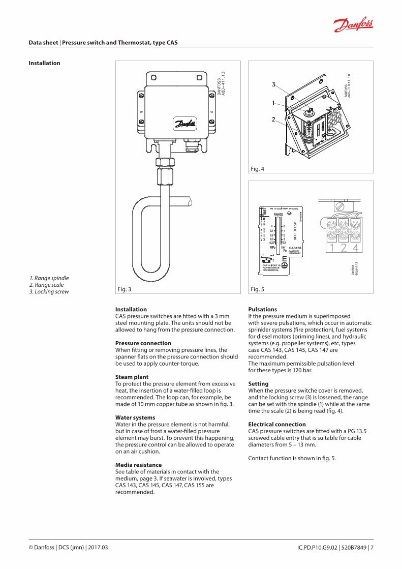
Installation
1. Range spindle2. Range scale3. Locking screw Fig. 3
Fig. 4
Fig. 5
© Danfoss | DCS (jmn) | 2017.03 IC.PD.P10.G9.02 | 520B7849 | 7
Data sheet | Pressure switch and Thermostat, type CAS
InstallationCAS pressure switches are fitted with a 3 mm steel mounting plate. The units should not be allowed to hang from the pressure connection.
Pressure connectionWhen fitting or removing pressure lines, the spanner flats on the pressure connection should be used to apply counter-torque.
Steam plant To protect the pressure element from excessive heat, the insertion of a water-filled loop is recommended. The loop can, for example, be made of 10 mm copper tube as shown in fig. 3.
Water systemsWater in the pressure element is not harmful, but in case of frost a water-filled pressure element may burst. To prevent this happening, the pressure control can be allowed to operate on an air cushion.
Media resistanceSee table of materials in contact with the medium, page 3. If seawater is involved, types CAS 143, CAS 145, CAS 147, CAS 155 are recommended.
PulsationsIf the pressure medium is superimposed with severe pulsations, which occur in automatic sprinkler systems (fire protection), fuel systems for diesel motors (priming lines), and hydraulic systems (e.g. propeller systems), etc, types case CAS 143, CAS 145, CAS 147 are recommended. The maximum permissible pulsation level for these types is 120 bar.
SettingWhen the pressure switche cover is removed, and the locking screw (3) is lossened, the range can be set with the spindle (1) while at the same time the scale (2) is being read (fig. 4).
Electrical connectionCAS pressure switches are fitted with a PG 13.5 screwed cable entry that is suitable for cable diameters from 5 – 13 mm.
Contact function is shown in fig. 5.
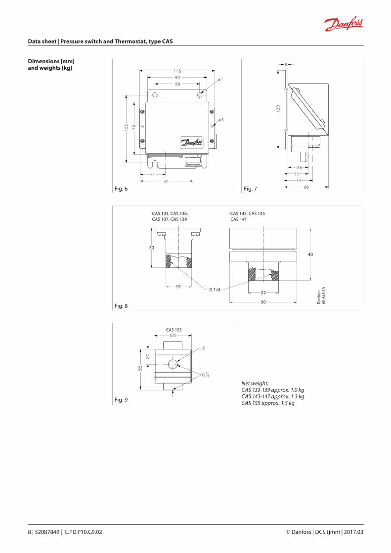
Fig. 6 Fig. 7
CAS 133, CAS 136, CAS 143, CAS 145CAS 137, CAS 139 CAS 147
Dan
foss
60-6
48.1
0
30
19G 1/4
22
40
50
Fig. 9
Fig. 8
Data sheet | Pressure switch and Thermostat, type CAS
© Danfoss | DCS (jmn) | 2017.038 | 520B7849 | IC.PD.P10.G9.02
Dimensions [mm]and weights [kg]
Net weight:CAS 133-139 approx. 1.0 kgCAS 143-147 approx. 1.3 kgCAS 155 approx. 1.5 kg
CAS 155
© Danfoss | DCS (jmn) | 2017.03 IC.PD.P10.G9.02 | 520B7849 | 9
Data sheet | Pressure switch and Thermostat, type CAS
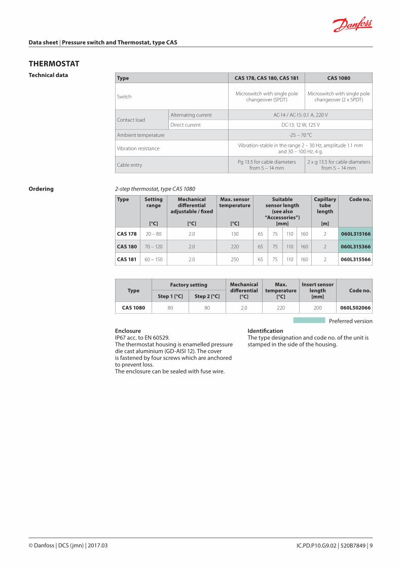
EnclosureIP67 acc. to EN 60529. The thermostat housing is enamelled pressure die cast aluminium (GD-AISI 12). The cover is fastened by four screws which are anchored to prevent loss.The enclosure can be sealed with fuse wire.
IdentificationThe type designation and code no. of the unit is stamped in the side of the housing.
Ordering
Type Setting range
[°C]
Mechanical differential
adjustable / fixed
[°C]
Max. sensor temperature
[°C]
Suitable sensor length
(see also “Accessories”)
[mm]
Capillary tube
length
[m]
Code no.
CAS 178 20 – 80 2.0 130 65 75 110 160 2 060L315166
CAS 180 70 – 120 2.0 220 65 75 110 160 2 060L315366
CAS 181 60 – 150 2.0 250 65 75 110 160 2 060L315566
TypeFactory setting Mechanical
differential[°C]
Max. temperature
[°C]
Insert sensor length[mm]
Code no.Step 1 [°C] Step 2 [°C]
CAS 1080 80 80 2.0 220 200 060L502066
Type CAS 178, CAS 180, CAS 181 CAS 1080
Switch Microswitch with single pole changeover (SPDT)
Microswitch with single pole changeover (2 x SPDT)
Contact loadAlternating current AC-14 / AC-15: 0.1 A, 220 V
Direct current DC-13: 12 W, 125 V
Ambient temperature -25 – 70 °C
Vibration resistance Vibration-stable in the range 2 – 30 Hz, amplitude 1.1 mm and 30 – 100 Hz, 4 g.
Cable entry Pg 13.5 for cable diameters from 5 – 14 mm
2 x g 13.5 for cable diameters from 5 – 14 mm
Technical data
THERMOSTAT
Preferred version
2-step thermostat, type CAS 1080
Data sheet | Pressure switch and Thermostat, type CAS
© Danfoss | DCS (jmn) | 2017.0310 | 520B7849 | IC.PD.P10.G9.02
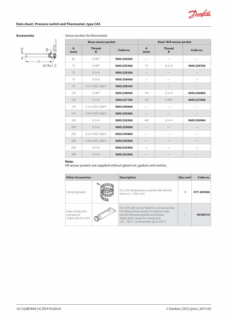
Accessories
Brass sensor pocket Steel 18/8 sensor pocket
A[mm]
Thread B Code no. A
[mm]Thread
B Code no.
65 ½ NPT 060L326566 — — —
75 ½ NPT 060L326466 75 G ½ A 060L326766
75 G ½ A 060L326266 — — —
75 G ¾ A 060L326666 — — —
75 G ½ A (ISO 228/1) 060L328166 — — —
110 ½ NPT 060L328066 110 G ½ A 060L326866
110 G ½ A 060L327166 110 ½ NPT 060L327066
110 G ½ A (ISO 228/1) 060L340666 — — —
110 G ¾ A (ISO 228/1) 060L340366 — — —
160 G ½ A 060L326366 160 G ½ A 060L326966
200 G ½ A 060L320666 — — —
200 G ½ A (ISO 228/1) 060L340866 — — —
200 G ¾ A (ISO 228/1) 060L340266 — — —
250 G ½ A 060L325466 — — —
330 G ½ A 060L325566 — — —
Other Accessories Description Qty./unit Code no.
Clamping band For CAS temperature controls with remote sensor (L = 392 mm). 10 017-420466
Heat conductive compound (Tube with 4.5 cm3)
For CAS with sensor fitted in a sensor pocket.For filling sensor pocket to improve heat transfer between pocket and sensor.Application range for compound: -20 – 150 °C, momentarily up to 220 °C.
1 041E0114
Note: All sensor pockets are supplied without gland nut, gaskets and washes.
Sensor pockets for thermostats
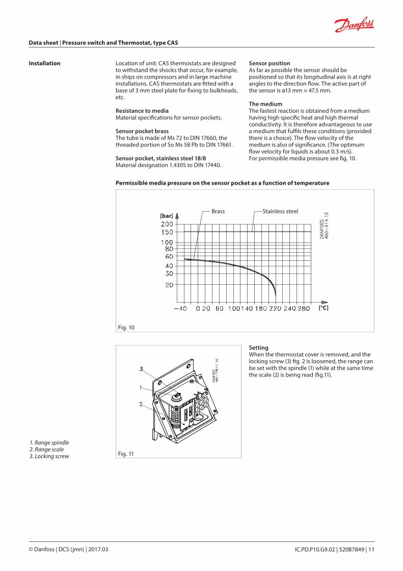
Fig. 11
1. Range spindle2. Range scale3. Locking screw
© Danfoss | DCS (jmn) | 2017.03 IC.PD.P10.G9.02 | 520B7849 | 11
Data sheet | Pressure switch and Thermostat, type CAS
Installation Location of unit: CAS thermostats are designed to withstand the shocks that occur, for example, in ships on compressors and in large machine installations. CAS thermostats are fitted with a base of 3 mm steel plate for fixing to bulkheads, etc.
Resistance to mediaMaterial specifications for sensor pockets.
Sensor pocket brassThe tube is made of Ms 72 to DIN 17660, the threaded portion of So Ms 58 Pb to DIN 17661.
Sensor pocket, stainless steel 18/8 Material designation 1.4305 to DIN 17440.
Sensor positionAs far as possible the sensor should be positioned so that its longitudinal axis is at right angles to the direction flow. The active part of the sensor is ø13 mm × 47.5 mm.
The mediumThe fastest reaction is obtained from a medium having high specific heat and high thermal conductivity. It is therefore advantageous to use a medium that fulfils these conditions (provided there is a choice). The flow velocity of the medium is also of significance. (The optimum flow velocity for liquids is about 0.3 m/s).For permissible media pressure see fig. 10.
SettingWhen the thermostat cover is removed, and the locking screw (3) fig. 2 is loosened, the range can be set with the spindle (1) while at the same time the scale (2) is being read (fig.11).
[°C]
[bar]
Permissible media pressure on the sensor pocket as a function of temperature
Brass Stainless steel
Fig. 10
Dan
foss
60-4
13.1
2
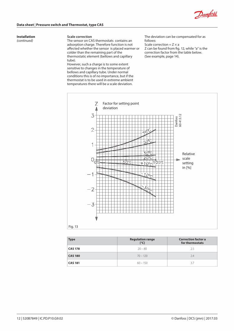
Factor for setting point deviation
Relativescalesettingin [%]
Fig. 13
Data sheet | Pressure switch and Thermostat, type CAS
© Danfoss | DCS (jmn) | 2017.0312 | 520B7849 | IC.PD.P10.G9.02
Scale correctionThe sensor on CAS thermostats contains an adsorption charge. Therefore function is not affected whether the sensor is placed warmer or colder than the remaining part of the thermostatic element (bellows and capillary tube). However, such a charge is to some extent sensitive to changes in the temperature of bellows and capillary tube. Under normal conditions this is of no importance, but if the thermostat is to be used in extreme ambient temperatures there will be a scale deviation.
The deviation can be compensated for as follows:Scale correction = Z × aZ can be found from fig. 12, while “a” is the correction factor from the table below. (See example, page 14).
Type Regulation range [°C]
Correction factor a for thermostats
CAS 178 20 – 80 2.5
CAS 180 70 – 120 2.4
CAS 181 60 – 150 3.7
Installation(continued)
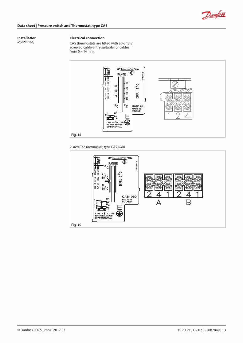
Fig. 14
Fig. 15
Dan
foss
60L1
049.
11
Dan
foss
60L1
049.
11
Dan
foss
60-1
121.
16
Dan
foss
60-1
121.
16
© Danfoss | DCS (jmn) | 2017.03 IC.PD.P10.G9.02 | 520B7849 | 13
Data sheet | Pressure switch and Thermostat, type CAS
Electrical connectionCAS thermostats are fitted with a Pg 13.5 screwed cable entry suitable for cables from 5 – 14 mm.
Installation(continued)
2-step CAS thermostat, type CAS 1080
Data sheet | Pressure switch and Thermostat, type CAS
© Danfoss | DCS (jmn) | 2017.0314 | 520B7849 | IC.PD.P10.G9.02
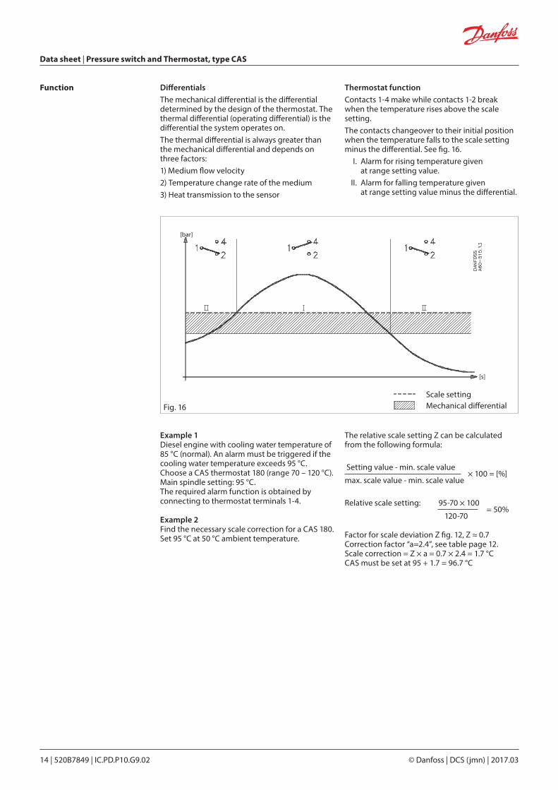
Function DifferentialsThe mechanical differential is the differential determined by the design of the thermostat. The thermal differential (operating differential) is the differential the system operates on.The thermal differential is always greater than the mechanical differential and depends on three factors:1) Medium flow velocity2) Temperature change rate of the medium3) Heat transmission to the sensor
Thermostat functionContacts 1-4 make while contacts 1-2 break when the temperature rises above the scale setting.The contacts changeover to their initial position when the temperature falls to the scale setting minus the differential. See fig. 16. I. Alarm for rising temperature given
at range setting value. II. Alarm for falling temperature given
at range setting value minus the differential.
Example 1Diesel engine with cooling water temperature of 85 °C (normal). An alarm must be triggered if the cooling water temperature exceeds 95 °C. Choose a CAS thermostat 180 (range 70 – 120 °C).Main spindle setting: 95 °C.The required alarm function is obtained by connecting to thermostat terminals 1-4.
Example 2Find the necessary scale correction for a CAS 180. Set 95 °C at 50 °C ambient temperature.
The relative scale setting Z can be calculated from the following formula:
Setting value - min. scale value
max. scale value - min. scale value × 100 = [%]
Relative scale setting: 95-70 × 100 = 50%
120-70 Factor for scale deviation Z fig. 12, Z ≈ 0.7Correction factor “a=2.4”, see table page 12.Scale correction = Z × a = 0.7 × 2.4 = 1.7 °CCAS must be set at 95 + 1.7 = 96.7 °C
Scale settingMechanical differentialFig. 16
[bar]
[s]
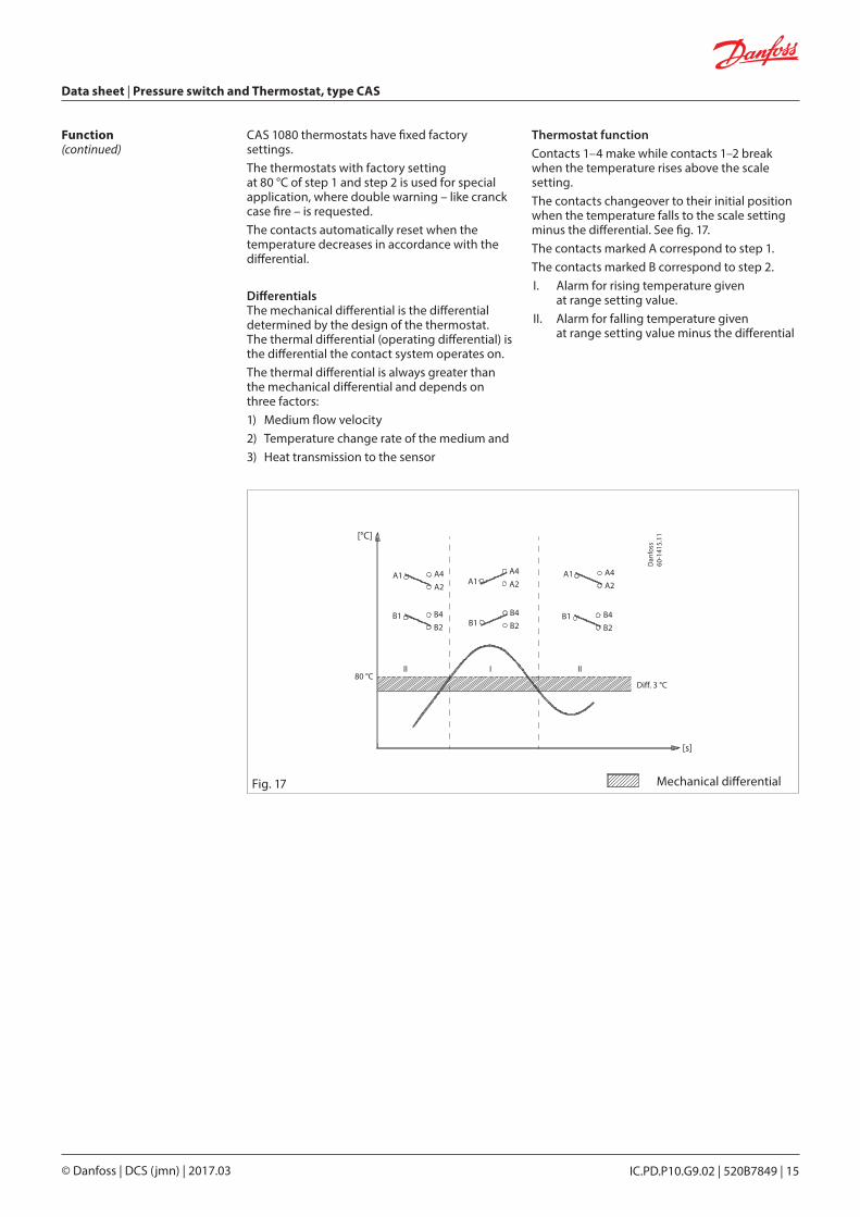
CAS 1080 thermostats have fixed factory settings. The thermostats with factory setting at 80 °C of step 1 and step 2 is used for special application, where double warning – like cranck case fire – is requested.The contacts automatically reset when the temperature decreases in accordance with the differential.
Differentials The mechanical differential is the differential determined by the design of the thermostat. The thermal differential (operating differential) is the differential the contact system operates on.The thermal differential is always greater than the mechanical differential and depends on three factors:1) Medium flow velocity2) Temperature change rate of the medium and3) Heat transmission to the sensor
Thermostat functionContacts 1–4 make while contacts 1–2 break when the temperature rises above the scale setting.The contacts changeover to their initial position when the temperature falls to the scale setting minus the differential. See fig. 17.The contacts marked A correspond to step 1.The contacts marked B correspond to step 2.I. Alarm for rising temperature given
at range setting value. II. Alarm for falling temperature given
at range setting value minus the differential
Function(continued)
© Danfoss | DCS (jmn) | 2017.03 IC.PD.P10.G9.02 | 520B7849 | 15
Data sheet | Pressure switch and Thermostat, type CAS
Mechanical differentialFig. 17
Temp [°C]
Time [s]
80 °CDiff. 3 °C
A1 A4A2
A1A4A2
B1B4B2
B1 B4B2
A1 A4A2
B1 B4B2
Dan
foss
60-1
415.
11
II III
[°C]
[s]
© Danfoss | DCS (jmn) | 2017.03 IC.PD.P10.G9.02 | 520B7849 | 16
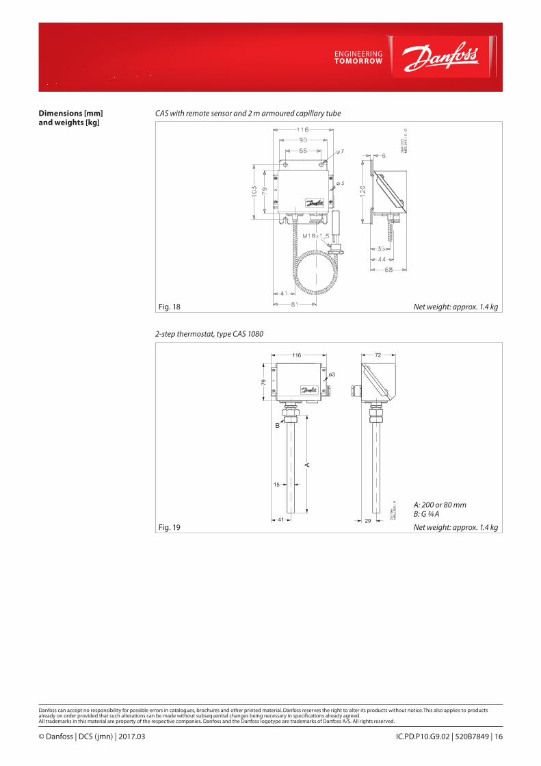
Dimensions [mm] and weights [kg]
Net weight: approx. 1.4 kg
Net weight: approx. 1.4 kg
CAS with remote sensor and 2 m armoured capillary tube
2-step thermostat, type CAS 1080
A: 200 or 80 mmB: G 3/4 A
Fig. 18
Fig. 19