Embed Size (px)
Citation preview
MNU, MNS, MNR, MNC, MNX, MNL ... or CUI Speaker: Chris Lindner – WD Partners
GD10menus e procedures for creating, sharing and editing toolbar , menus, dashboards, shortcuts, mouse buttons, workspaces, and even touches on how to migrate legacy chnologies (table, screen and image menus.. remember those?) safely and quickly.
• C• S• W
About the Speaker: Chris is a veteran AutoCAD user of over 20 years. He has been a CAD drafter, CAD manager, trainer, and consultant in a variety of industries. He is currently the Director of CAD technology for WD Partners, an international, multi-unit design and development firm. Chris is currently serving as the Vice President for the AUGI Board of Directors, and is Manager of AUGI's monthly HotNews publication where he also writes the popular TIPniques column.
5-2P This course guides anyone familiar the two-dec into the uncharted territory of the new CUIs. It outlines th
ade-old method of customizing AutoCAD's
ste
After attending this class, you will be able to: • Use previous menu knowledge to accelerate the CUI learning curve
reate CUI files from existing MNU/MNS files et up Enterprise and Main CUI files ork with workspaces and dashboards

2
1 Introduction Since AutoCAD 2006, Autodesk has taken some innovative steps to modernizing how we tailor the AutoCAD environment. Rather than having to do customization with a variety of tools, practically all of
s (toolbars, menus, shortcuts, etc.) can be modified and managed ew Customize User Interface (CUI) editor. This course will give you
the f
2 The acc
2.1 What I Won’t Miss n by accidentally loading the edited from within AutoCAD)
terminated or forgotten to terminate a cascade menu with the “<-“ code, you know what this is about.
I releases of AutoCAD had a mind of their own when it . No longer will it create icons with names like
r for some of the heavy lifting and tweaking.
down menu, when you
2.2
AutoCAD’s user interface (UI) elementfrom within AutoCAD itself using the n
undamentals to fully leverage the new CUI
Out with the MNU, in with the New CUI is not perfect, but is a step in the right direction. For years, users have lived with and come to
ept the nuances of MNU/MNS files.
• Edit the MNU or MNS file? – I think we’ve all lost some customizatioMNU file, overwriting some modifications that had been save (when to the MNS.
• Cascading problems - If you’ve ever incorrectly
• Randomly named icons files – Pre-CUcame to naming and placing BMP filesRCDA4295.bmp placed in hard-to-predict folders.
• Multiple editors – You could edit a few things from inside AutoCAD, but you always had to resort to an external text edito
• Edit-Load-Test cycle – Since MNU/MNS files had to be compiled, testing your customizations required you to exit AutoCAD or unload and reload the menu.
• Single definition of macros – If you placed a macro on a toolbar and a pull-needed to change it, you had to remember to do it in each place.
• Transferring customization between menus – Knowing what to copy from one MNU/MNS and where to paste it in another could be tricky.
• Sharing\protecting company menus – The only option with MNU/MNS files was to rely on the file’s read-only attribute or placing them on a secure network location.
The More Things Change… • Macros – Macro syntax is the same as before.
• Icon editor – The clunky icon editor is unchanged, and unimproved.
• Partial menus – Same as before.
• Menu-related AutoLISP (MNL) files – No change.
3
3 Comparisons When learning something new, making a connection between what you knew and what is new can flatten the learning curve. This section will build in your knowledge of customization in pre-CUI releases. We will
files.
3.1
look at the CUI as it relates to MNU/MNS
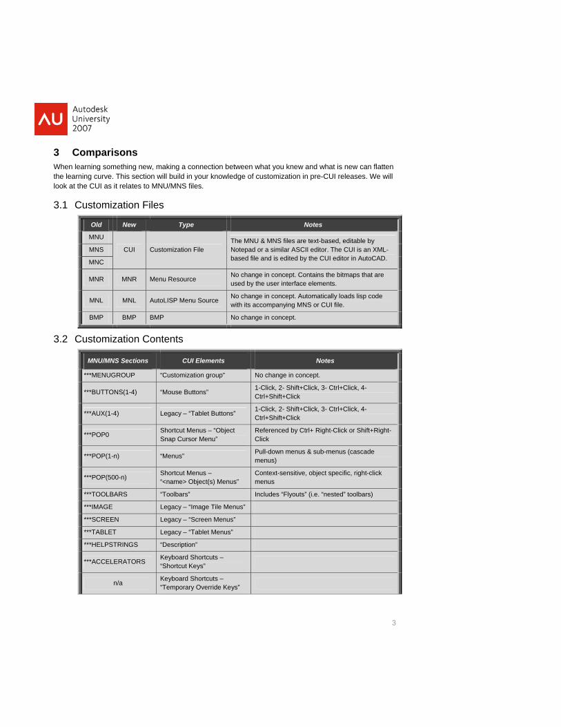
Customization Files
Old New Type Notes
MNU
CUI Customization File The MNU & MNS files are text-based, editable by Notepad or a similar ASCII editor. The CUI is an XML-based file and is edited by the CUI editor in AutoCAD.
MNS
MNC
MNR MNR M source enu Re No change in concept. Contains the bitmaps that are used by the user interface elements.
MNL MNL AutoLISP Menu Source No change in concept. Automatically loads lisp code with its accompanying MNS or CUI file.
BMP BMP BMP No change in concept.
3.2 Customization Contents
MNU/MNS Sections CUI Elements Notes
***MENU GROUP “Customization group” No change in concept.
***BUTT ) ONS(1-4 “Mouse Buttons” 1-Click, 2- Shift+Click, 3- Ctrl+Click, 4- Ctrl+Shift+Click
***AUX(1-4) Legacy – “Tablet Buttons” 1-Click, 2- Shift+Click, 3- Ctrl+Click, 4- Ctrl+Shift+Click
***POP0 Shortcut Menus – “Object Snap Cursor Menu”
Referenced by Ctrl+ Right-Click or Shift+Right-Click
***POP(1-n) “Menus” Pull-down menus & sub-menus (cascade menus)
***POP(500-n) Shortcut Menus – “<name> Object(s) Menus”
Context-sensitive, object specific, right-click menus
***TOOLBARS “Toolbars” Includes “Flyouts” (i.e. “nested” toolbars)
***IMAGE Legacy – “Image Tile Menus”
***SCREEN Legacy – “Screen Menus”
***TABLET Legacy – “Tablet Menus”
***HELPSTRINGS “Description”
***ACCELERATORS Keyboard Shortcuts – “Shortcut Keys”
n/a Keyboard Shortcuts – “Temporary Override Keys”
4
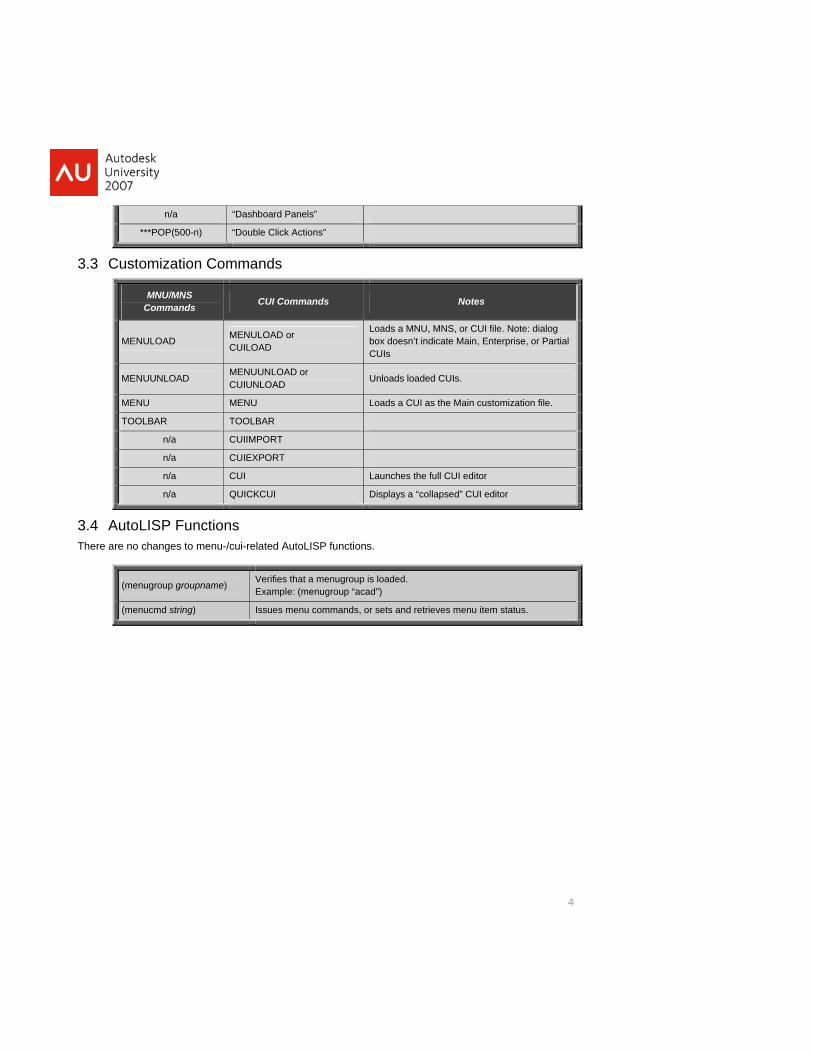
n/a “Dashboard Panels”
***POP(500-n) “Double Click Actions”
3.3 Customization nds Comma
MNU/MNS Commands CUI Commands Notes
MENULOAD MENULOAD or CUILOAD
Loads a MNU, MNS, or CUI file. Note: dialog box doesn’t indicate Main, Enterprise, or Partial CUIs
MENUUNLOAD MENUUNLOAD or CUIUNLOAD Unloads loaded CUIs.
MENU MENU Loads a CUI as the Main customization file.
TOOLBAR TOOLBAR
n/a CUIIMPORT
n/a CUIEXPORT
n/a CUI Launches the full CUI editor
n/a QUICKCUI Displays a “collapsed” CUI editor
3.4 AutoLI ns There are no changes to menu-/cui-related A ns.
SP FunctioutoLISP functio
(menugroup groupn ) ame Verifies is loaded. that a menugroupExampl nugroup “acad") e: (me
(menucmd string) Issues men or sets and retrieves menu commands, u item status.
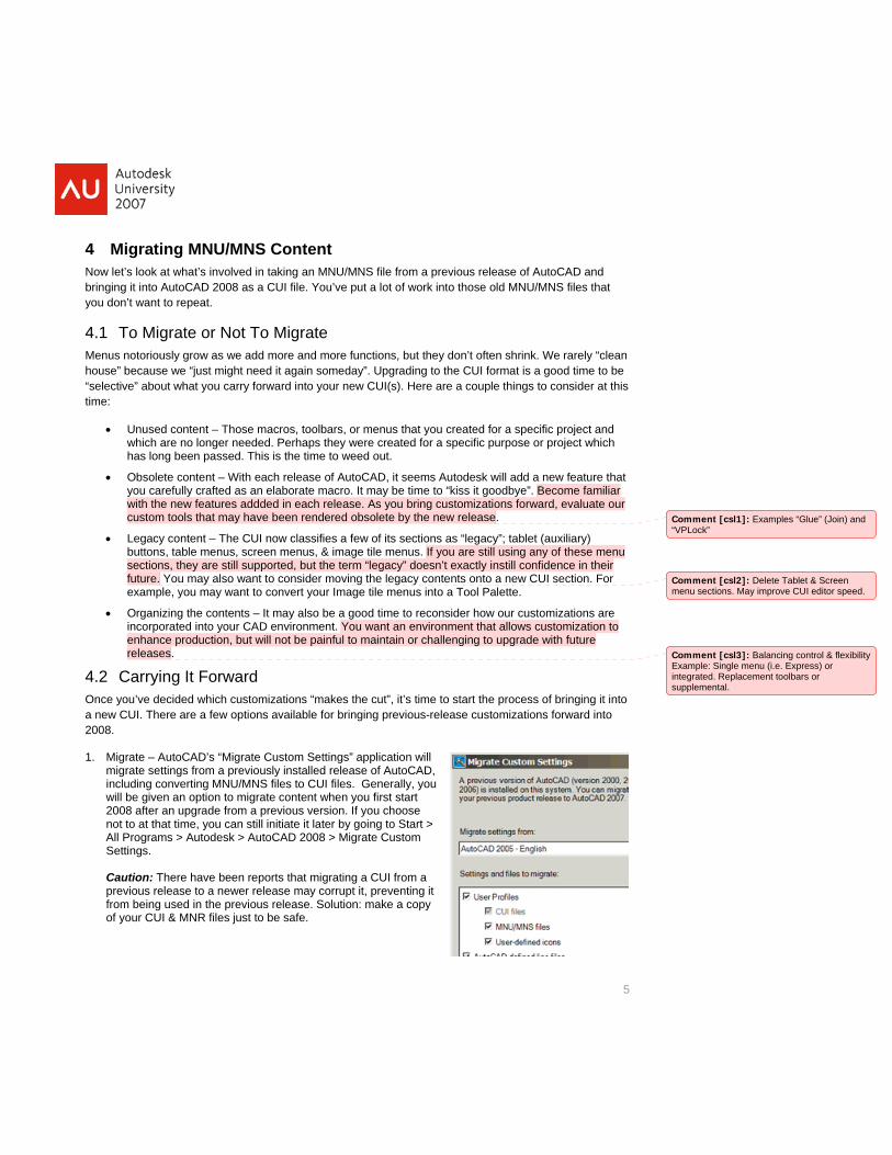
4 Migrating MNU/MNS Content Now let’s look at what’s involved in taking an MNU/MNS file from a previous release of AutoCAD and bringing it into AutoCAD 2008 as a CUI file. You’ve put a lot of work into those old MNU/MNS files that
4.1Menhou“sel rd into your new CUI(s). Here are a couple things to consider at this
you created for a specific project and
you don’t want to repeat.
To Migrate or Not To Migrate us notoriously grow as we add more and more functions, but they don’t often shrink. We rarely “clean
se” because we “just might need it again someday”. Upgrading to the CUI format is a good time to be ective” about what you carry forwa
time:
• Unused content – Those macros, toolbars, or menus thatwhich are no longer needed. Perhaps they were created for a specific purpose or project which has long been passed. This is the time to weed out.
• Obsolete content – With each release of AutoCAD, it seems Autodesk will add a new feature that you carefully crafted as an elaborate macro. It may be time to “kiss it goodbye”. Become familiar with the new features addded in each release. As you bring customizations forward, evaluate our custom tools that may have been rendered obsolete by the new release.
5
• Legacy content – The CUI now classifies a few of its sections as “legacy”; tablet (auxiliary) buttons, table menus, screen menus, & image tile menus. If you are still using any of these menu sections, they are still supported, but the term “legacy” doesn’t exactly instill confidence in their future. You may also want to consider moving the legacy contents onto a
Comment [csl1]: Examples “Glue” (Join) and “VPLock”
new CUI section. For example, you may want to convert your Image tile menus into a Tool Palette.
• Organizing the contents – It may also be a good time to reconsider how our customizations are incorporated into your CAD environment. You want an environment that allows customization to enhance production, but will not be painful to maintain or challenging to upgrade with future releases.
Comment [csl2]: Delete Tablet & Screen CUI editor speed.menu sections. May improve
4.2 Carrying It Forward ou’ve decided which customizations “makes the cut”, it’s time to start the process of bringing it into
CUI. There are a few options available for bringing previous-release customizations forward into 8.
Once ya new200
1.
an still initiate it later by going to Start > igrate Custom
UI & MNR files just to be safe.
Comment [csl3]: Balancing control & flexibilityenu (i.e. Express) or ement toolbars or
Example: Single mintegrated. Replacsupplemental.
Migrate – AutoCAD’s “Migrate Custom Settings” application will migrate settings from a previously installed release of AutoCAD, including converting MNU/MNS files to CUI files. Generally, you will be given an option to migrate content when you first start 2008 after an upgrade from a previous version. If you choose not to at that time, you cAll Programs > Autodesk > AutoCAD 2008 > MSettings. Caution: There have been reports that migrating a CUI from a previous release to a newer release may corrupt it, preventing it from being used in the previous release. Solution: make a copy of your C

6
2. Convert – There are various ways that you can “open” or load an MNU/MNS file. You can use the “Open” icon in the CUI editor, or use the CUILOAD command. However you choose to do it, AutoCAD will convert it in its entirety to a CUI file automatically.
: When converting a MNU/MNS in this fashion, the related MNR file gets rebuilt, rendering it
ou prefer to be selective about what you bring forward, then the CUI editor’s Transfer
If the MNU/MNS file you are converting has partials under it, then they will be converted to CUIs as well. Cautionunusable in previous versions of AutoCAD.
3. Transfer – If ytab will be your best bet. The Transfer tab essentially lets you have two CUI files open simultaneously, letting you drag-and-drop from one to another. You can use the Transfer tab to “save” content that you don’t want to delete by putting it in a “archive” cui. You can also use the CUIIMPORT command (Tools->Customize) which opens the CUI editor and defaults to the Transfer tab.
Comment [csl4]: Use the CShift-select to select multiple
trl-select and elements for
transferring.
Tip: In addition to converting MNU/MNS files, the Transfer tab can be used to “purge” existing CUI files. Just transfer the customization that you want to keep into a new CUI and save it as a new CUI file.
7
5 Managing CUI files The “CUI” acronym can mean many things. Not only is it an AutoCAD command, it represents a file type, as well as a type of Customization file. There are two types of Customization file assignments, “Main” and
a CUI file is loaded.
5.1Prioenfo solution. The s: any CUI
cusscethe file i
Spemad“CuCUI EntIn this futhe Enterprise customization file.
Sinc enting reas helps, it is nCom watruly
“Enterprise”. A third term, “partial”, refers to how
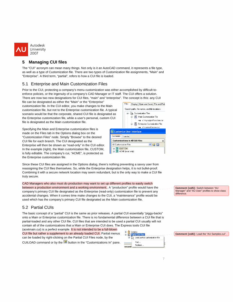
Enterprise and Main Customization Files r to the CUI, protecting a company’s menu customization was either accomplished by difficult-to-rce policies, or the ingenuity of a company’s CAD Manager or IT staff. The CUI offers a re are now two new designations for CUI files, “main” and “enterprise”. The concept is thi
file can be designated as either the “Main” or the “Enterprise” customization file. In the CUI editor, you make changes to the Main
tomization file, but not to the Enterprise customization file. A typical nario would be that the corporate, shared CUI file is designated as Enterprise customization file, while a user’s personal, custom CUI s designated as the Main customization file.
cifying the Main and Enterprise customization files is e on the Files tab in the Options dialog box on the
stomization Files” node. Simply “Browse” to the desired file for each branch. The CUI designated as the
erprise will then be shown as “read-only” in the CUI editor. e example (right), the Main customization file, CUSTOM, lly editable. The company’s cui, “ACME”, is protected as
e these CUI files are assigned in the Options dialog, there’s nothing prevsigning the CUI files themselves. So, while the Enterprise designation bining it with a secure network location may seem redundant, but is the only secure.
a savvy user from ot bullet-proof.
y to make a CUI file
CAD easily switch Managers who also must do production may want to set up different profiles tobetw file would have the een a production environment and a working environment.. A “production” pro
com n file to prevent any acci ce” profile would be use designated as the Main customization file.
5.2The ontopart y other CUI file. CUI files that are intended to be used a partial CUI usually will not contain all of the customizations that a Main or Enterprise CUI does. The Express tools CUI file
pany’s primary CUI file designated as the Enterprise (read-only) customizatiodental changes. When it comes time make changes to the CUI, a “maintenand which has the company’s primary CUI file
Partial CUIs basic concept of a “partial” CUI is the same as prior releases. A partial CUI essentially “piggy-backs” a Main or Enterprise customization file. There is no fundamental difference between a CUI file that is ial-loaded and an
(acetmain.cui) is a perfect example. It is not intended to be a full-blown CUI file but rather a supplement to an already loaded CUI. Partial menus can CUI
be loaded by right-clicking on the Partial CUI Files node, by the LOAD command or by the button in the “Customizations In” pane.
Comment [csl5]: Switch between “AU Manager” and “AU User” profiles to show class difference.
Comment [csl6]: Load the “AU Samples.cui”.
8
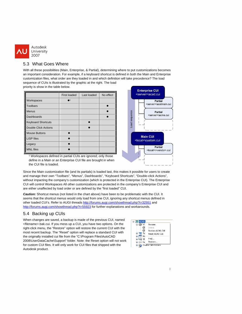
5.3 What Goes Where With all these possibilities (Main, Enterprise, & Partial), determining where to put customizations becomes an important consideration. For example, if a keyboard shortcut is defined in both the Main and Enterprise
in and which definition will take precedence? The load t the right. The load
prio
customization files, what order are they loadedsequence of CUIs is illustrated by the graphic a
rity is show in the table below.
First loaded Last loaded No effect
Workspaces ¹
Toolbars
Menus
Dash ards bo
Keyboard Shortcuts
Double Click Actions
Mouse Buttons
LISP files
Legacy
MNL files
¹ Worksp rtial CUIs are ignored; only those de rise CUI file e brought in whthe CU .
Since t omization file (and its partials) is loaded las it p le for userand ma wn “Toolbars”, “Menus”, ds”, “Key -withou the company’s customizat (which is protected in the Enterprise CUI). TCUI will cont kspaces All other customiz ons are protected in the compa y’s Enterprare eith d by load order or are defined by the “first lo ded” CUI.
Caution: th the Cseems th us dother loa 551
aces defined in pa fine in a Main or an Enterp ar en
I file is loaded
he Main custnage their o
t, this makes board Shortcuts”,
ossib “Double
s to create click Actions”,
he Enterprise ise CUI and
UI. It efined in
Dashboart impacting ion
rol Worer unaffecte
ati na
Shortcut menus (not listed in the chart above) have been to be problematic wiat the shortcut menus would only load from one CUI, ignoring any shortcut mended CUI’s. Refer to AUGI threads http://forums.augi.com/showthread.php?t=32 and
http://foru p?t=55923ms.augi.com/showthread.ph for further explanations and workarounds.
5.4Wh<filerighmosthe 200for cAut
Backing up CUIs en changes are saved, a backup is made of the previous CUI, named name>.bak.cui. If you mess up a CUI, you have two options. On the t-click menu, the “Restore” option will restore the current CUI with the t recent backup. The “Reset” option will replace a standard CUI with originally installed cui file from the “C:\Program Files\AutoCAD 8\UserDataCache\Support” folder. Note: the Reset option will not work ustom CUI files. It will only work for CUI files that shipped with the
odesk product.
6 Working with Commands A “command” is the basic building block in the CUI. It defines how the command looks and behaves in the CUI. This section explores what a CUI command, what it isn’t, how to create one and how to use them.
The
1. would type in at the
2.
ist
Is are listed in the Commands List pane.
y not be the AutoCAD e name that you would
see Comhigh ndactu
Sincactuafewdowpre-a sp
Alsoall lfoun
The “Search command list” will quickly filter the command list spe
6.1 When a Command is not a Command term “command” can refer to different things in AutoCAD. Here’s how I differentiate between them.
An “AutoCAD” command: This is a command that ships with AutoCAD. This is what we mean when we mention the “LINE” command or the “RENDER” command. It is what youcommand line.
A “custom” command: This would be a user-defined function, such as an alias, AutoLISP function or VBa routine.
3. A “CUI” command: A CUI command is basically a macro that calls an “AutoCAD” command or custom command. A CUI command contains properties to define what it does (in the form of a macro), and how it will appear on the interface (name, description, icon).
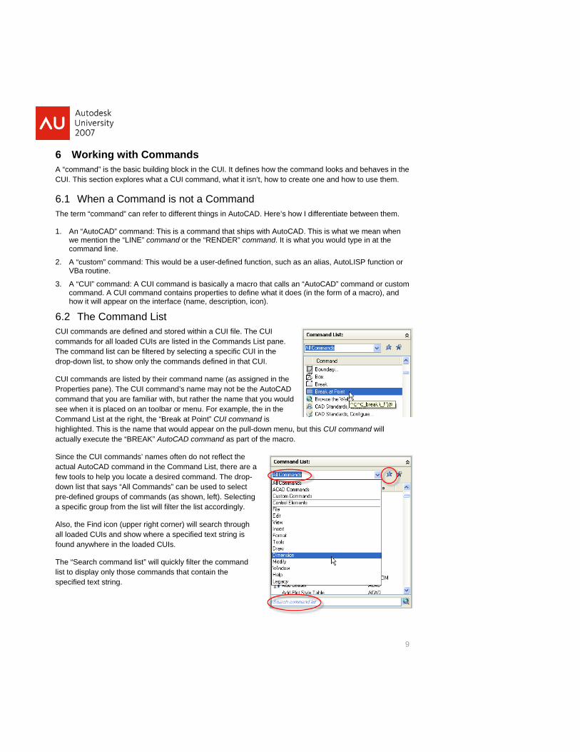
6.2 The Command LCUI commands are defined and stored within a CUI file. The CUI commands for all loaded CUThe command list can be filtered by selecting a specific CUI in the drop-down list, to show only the commands defined in that CUI.
CUI commands are listed by their command name (as assigned in the
9
Properties pane). The CUI command’s name macommand that you are familiar with, but rather th
when it is placed on an toolbar or menu. For example, the in the mand List at the right, the “Break at Point” CUI command is lighted. This is the name that would appear on the pull-down menu, but this CUI commaally execute the “BREAK” AutoCAD command as part of the macro.
e the CUI commands’ names often do not reflect the
will
l AutoCAD command in the Command List, there are a tools to help you locate a desired command. The drop-n list that says “All Commands” can be used to select defined groups of commands (as shown, left). Selecting ecific group from the list will filter the list accordingly.
, the Find icon (upper right corner) will search through oaded CUIs and show where a specified text string is d anywhere in the loaded CUIs.
to display only those commands that contain the cified text string.
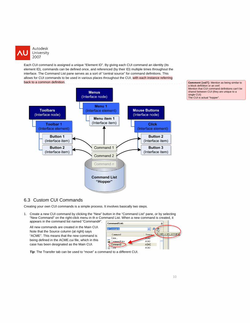
Each CUI command is assigned a unique “Element ID”. By giving each CUI command an identity (its element interface.
ID), commands can be defined once, and referenced (by their ID) multiple times throughout the The Command List pane serves as a sort of “central source” for command definitions. This
allows for CUI commands to be used in various places throughout the CUI, with each instance referring
10
back to a common definition.
6.3 Custom CUI Commands Creating your own CUI commands is a simple process. It involves basically two steps.
1. Create a new CUI command by clicking the “New” button in the “Command List” pane, or by selecting “New Command” on the right-click menu in th e Command List. When a new command is created, it appears in the command list named “Command#”.
All new commands are created in the Main CUI. Note that the Source column (at right) says “ACME". This means that the new command is being defined in the ACME.cui file, which in this case has been designated as the Main CUI.
and to a different CUI.
Comment [csl7]: Mea block definition or an xrefMention that CUI commandshared between CUI (single CUI) The CUI is actual “hopper”
ntion as being similar to . definitions can’t be
they are unique to a
.
Tip: The Transfer tab can be used to “move” a comm
11
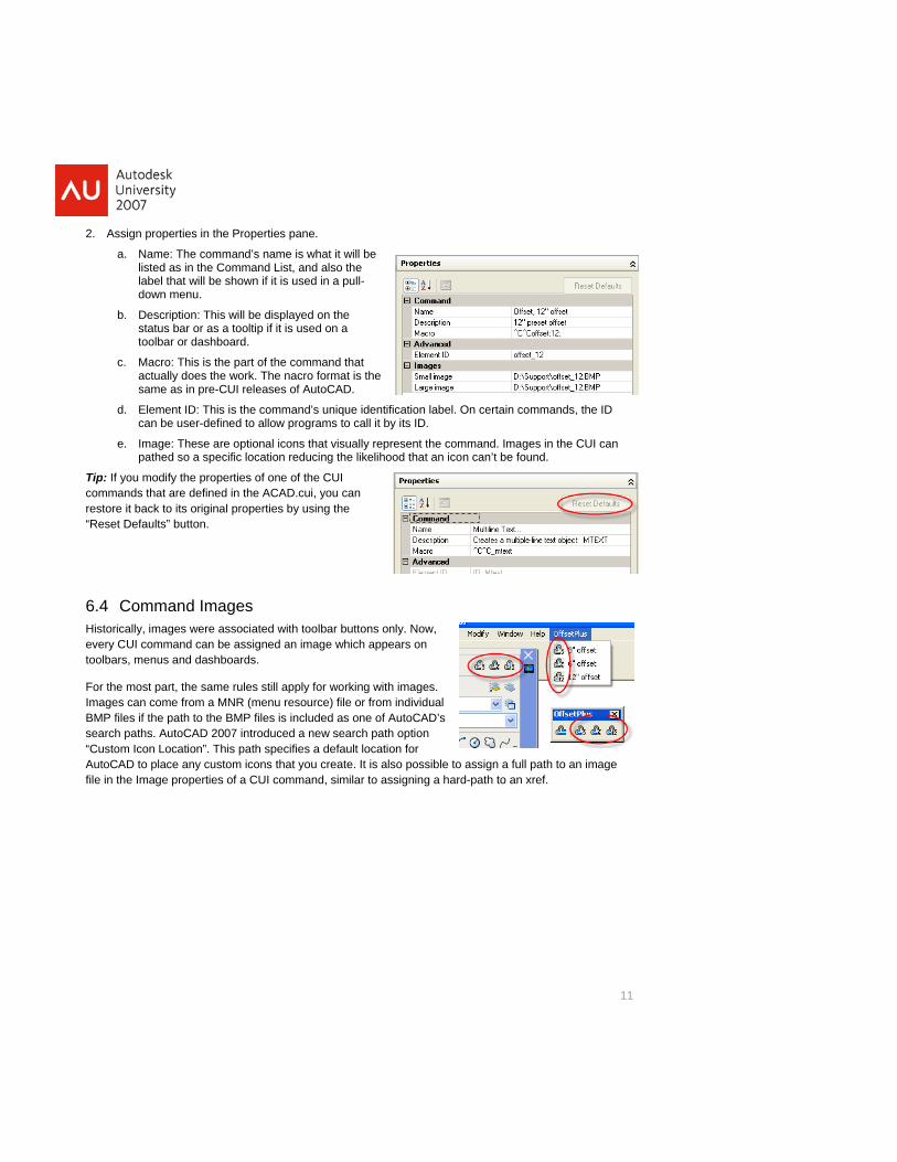
2. Assign properties in the Properties pane.
a. Name: The command’s name is what it will be listed as in the Command List, and also the
he nacro format is the
nn can’
Tip: comm
“Reset Default
6.4Histevetool
For part, the same rules still apply for working with images. Images can come from a MNR (menu resource) file or from individual BM if the path to the BMP files is included as one of AutoCAD’s search paths. AutoCAD 2007 introduced a new search path option
fault location for ate. It is also possible to assign a full path to an image
file i
label that will be shown if it is used in a pull-down menu.
b. Description: This will be displayed on the status bar or as a tooltip if it is used on a toolbar or dashboard.
c. Macro: This is the part of the command that actually does the work. Tsame as in pre-CUI releases of AutoCAD.
d. Element ID: This is the command’s unique identification label. Oncan be user-defined to allow programs to call it by its ID.
certain commands, the ID
d. Images in the CUI can t be found.
e. Image: These are optional icons that visually represent the commapathed so a specific location reducing the likelihood that an ico
If you modify the properties of one of the CUI ands that are defined in the ACAD.cui, you can
restore it back to its original properties by using the s” button.
Command Images orically, images were associated with toolbar buttons only. Now, ry CUI command can be assigned an image which appears on bars, menus and dashboards.
the most
P files
“Custom Icon Location”. This path specifies a deAutoCAD to place any custom icons that you cre
n the Image properties of a CUI command, similar to assigning a hard-path to an xref.

12
7 Interface Elements In order for a CUI command to actually be used and visible in AutoCAD, it must be placed on an “interface element”. Elements may be visible on the interface (like pull-down menus, toolbars, etc,) or just
tc.). Populating most interface elements is simply a m the Command List pane (remember the “hopper”?).
This
7.1Toocrea
1.
rag-and-dropping nto the “OffsetPlus” toolbar. It is possible to drag-and-rop multiple commands at a time using Shift+pick or ontrol+pick when selecting commands. It is not ossible to drag items from one interface element to
another (Ex. from Toolbar to a Menu).
on’t forget about the Find and Search tools mentioned i Section 6.2.
Once placed on the toolbar, commands can be
l name”. This allows the name that appears on
t List pane, but different names can be used to impr
assignments (like keyboard shortcuts, overrides, eprocess of “dragging-and-dropping” commands fro
section looks at the various elements and their unique properties.
Toolbars, Menus, and Dashboards lbars, menus and dashboards are created very similar within the CUI editor. In this exercise, we will te a new toolbar for some custom OFFSET commands.
Create a new toolbar by right-clicking on the Toolbars node, select New, and changing its default name (Toolbar#) to “OffsetPlus”. Toolbars (and all other Interface elements), like CUI commands, have their own set of properties (right).
2. Place commands on the toolbar by dodCp
Dn
rearranged by dragging them into the order desired. Separators can be added (to group like commands together) by right-clicking on an interface item.
Tip: When a CUI command is placed on a Toolbar, Menu or Dashboard, the Properties pane shows a new field, the “Disp aythe Menu or as a tooltip to be different from the CUI’s command name. In this way CUI command names can be structured in a way thathey are listed in the Command AutoCAD’s interface.
makes sense when ove how they appear in
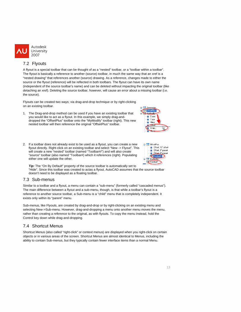
7.2 Flyouts A flyout is a special toolbar that can be thought of as a “nested” toolbar, or a “toolbar within a toolbar”. The flyout is basically a reference to another (source) toolbar, in much the same way that an xref is a
es another (source) drawing. As a reference, changes made to either the ) will be reflected in both toolbars. The flyout can have its own name
(inddetathe
Flyoon a
1.
setPlus” toolbar onto the “MyModify” toolbar (right). This new
p: The “On By Default” property of the source toolbar is automatically set to ide”. Since this toolbar was created to actas a flyout, AutoCAD assumes that the source toolbar
oesn’t need to be displayed as a floating toolbar.
Shoobjeabili
“nested drawing” that referencsource or the flyout (reference
ependent of the source toolbar’s name) and can be deleted without impacting the original toolbar (like ching an xref). Deleting the source toolbar, however, will cause an error about a missing toolbar (i.e.
source).
uts can be created two ways; via drag-and-drop technique or by right-clicking n existing toolbar.
The Drag-and-drop method can be used if you have an existing toolbar that you would like to act as a flyout. In this example, we simply drag-and-dropped the “Offnested toolbar will then reference the original “OffsetPlus” toolbar.
2. If a toolbar does not already exist to be used as a flyout, you can create a new flyout directly. Right-click on an existing toolbar and select “New -> Flyout”. This will create a new “nested” toolbar (named “Toolbar#/”) and will also create “source” toolbar (also named “Toolbar#) which it references (right). Populating either one will update the other. Ti“Hd
7.3 Sub-menus Similar to a toolbar and a flyout, a menu can contain a “sub-menu” (formerly called “cascaded menus”). The main difference between a flyout and a sub-menu, though, is that while a toolbar’s flyout is a reference to another source toolbar, a Sub-menu is a “child” menu that is completely independent. It exists only within its “parent” menu.
Sub-menus, like Flyouts, are created by drag-and-drop or by right-clicking on an existing menu and selecting New->Sub-menu. However, drag-and-dropping a menu onto another menu moves the menu, rather than creating a reference to the original, as with flyouts. To copy the menu instead, hold the Control key down while drag-and-dropping.
7.4 Shortcut Menus rtcut Menus (also called “right-click” or context menus) are displayed when you right-click on certain cts or in various areas of the screen. Shortcut Menus are almost identical to Menus, including the ty to contain Sub-menus, but they typically contain fewer interface items than a normal Menu.
13
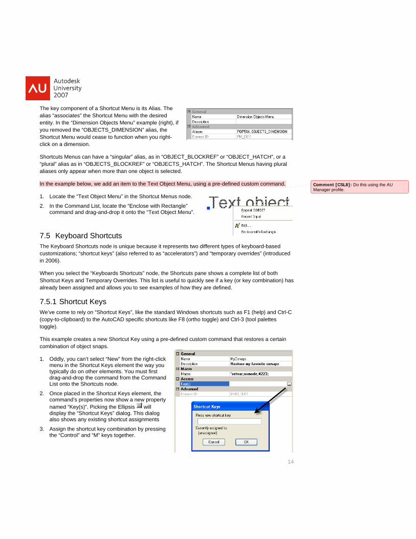
The key component of a Shortcut Menu is its Alias. The alias “associates” the Shortcut Menu with the desired entity. In the “Dimension Objects Menu” example (right), if you removed the “OBJECTS_DIMENSION” alias, the Shoclick
Sho“pluralia
rtcut Menu would cease to function when you right- on a dimension.
rtcuts Menus can have a “singular” alias, as in “OBJECT_BLOCKREF” or “Oal” alias as in “OBJECTS_BLOCKREF” or “OBJECTS_HATCH”. The S
ses only appear when more than one object is selected.
BJECT_HATCH”, or a hortcut Menus having plural
In th item to the Text Object Menu, using a pre-defined custom command.
14
e example below, we add an
1.
2.
7.5 Keyb
verrid
When you select the “Keyboards Shortcuts” node, the Shortcuts pane shows a complete Sho cut Keys and Temporary Overrides. This list is useful to quickly see if a key (or key
ples of how they are defined.
We’(coptogg
Thiscom
1.
first Command
2.
Comment [CSL8]: Do this using the AU Manager profile.
Locate the “Text Object Menu” in the Shortcut Menus node.
In the Command List, locate the “Enclose with Rectangle” command and drag-and-drop it onto the “Text Object Menu”.
yboard Shortcuts The Keyboard Shortcuts node is unique because it represents two different types of ke oard-based
es” (introduced
list of both combination) has
customizations; “shortcut keys” (also referred to as “accelerators”) and “temporary oin 2006).
rtalready been assigned and allows you to see exam
7.5.1 Shortcut Keys ve come to rely on “Shortcut Keys”, like the standard Windows shortcuts such as F1 (help) and Ctrl-C y-to-clipboard) to the AutoCAD specific shortcuts like F8 (ortho toggle) and Ctrl-3 (tool palettes le).
example creates a new Shortcut Key using a pre-defined custom command that restores a certain bination of object snaps.
Oddly, you can’t select “New” from the right-click menu in the Shortcut Keys element the way you typically do on other elements. You must drag-and-drop the command from theList onto the Shortcuts node.
Once placed in the Shortcut Keys element, the command’s properties now show a new property named “Key(s)”. Picking the Ellipsis will display the “Shortcut Keys” dialog. This dialog
3.
also shows any existing shortcut assignments
Assign the shortcut key combination by pressing the “Control” and “M” keys together.
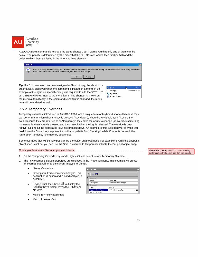
AutoCAactive. The priority is determined by the order that the CUI files are loaded (see Section 5.3) and the order in which they are listing in the Shortcut Keys element.
D allows commands to share the same shortcut, but it warns you that only one of them can be
Tip: If a CUI command has been assigned a Shortcut Key, the shortcut is automatically displayed when the command is placed on a menu. In the example at the right, no special coding was required to add the “CTRL+S” or “CTRL+SHIFT+S” next to the menu items. The shortcut is shown on the menu automatically. If the command’s shortcut is changed, the menu item will be updated as well.
7.5Temcan oboth somethmom ly “act pressed down. An example of this type behavior is when you hold dow olbar or palette from “docking”. While Control is pressed, the
Somobje
.2 Temporary Overrides porary overrides, introduced in AutoCAD 2006, are a unique form of keyboard shortcut because they
perform a function when the key is pressed (“key down”), when the key is released (“key up”), . Because they are referred to as “temporary”, they have the ability to change (or override)entarily when a key is pressed and then reset it when the key is released. The override is on
ive” as long as the associated keys aren the Control key to prevent a to
r
ing
15
“auto-dock” tendency is temporary suspended.
e overrides that will be very popular are the object snap overrides. For example, even if the Endpoint ct snap is not on, you can use the Shift+E override to temporarily activate the Endpoint object snap.
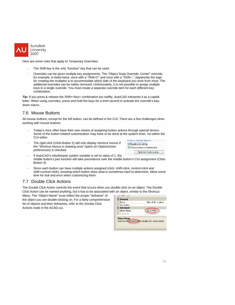
Creating a Temporary Override, goes as follows:
1.
2.
• Description: Force centerline linetype This
Key(s): Click the Ellipsis
On the Temporary Override Keys node, right-click and select New > Temporary Override.
The new override’s default properties are displayed in the Properties pane. This example will create an override that will force the current linetype to Center.
• Name: Centerline
description is option and is not displayed in AutoCAD.
• to display the Shortcut Keys dialog. Press the “Shift” and “1” keys.
Comment [CSL9]: Trivia: TOcustomization that do not use CUI com
’s are the only mands!
• Macro 1: ^P‘celtype;center;
• Macro 2: leave blank
Here are some rules that apply to Temporary Overrides:
- The Shift key is the only “function” key that can be used.
Override: Center” override, hift+,”. Apparently the logic
for creating the multiples is to accommodate which side of the keyboard you work from most. The assign multiple fferent key
Tip:letdow
7.All mwor
often have their own means of assigning button actions through special drivers. utton-related customization may have to be done at the system level, not within the
only display shortcut menus if
variable is set to value of 1, the middle button’s pan function will take precedence over the middle button’s CUI assignment (Click-
nowing which button does what is sometimes hard to determine. Allow some r when customizing them.
Th rs when you double-click on an object. The DoClic be associated with an object, similar to the Shortcut
the list es, refer to the Double Click Act
- Overrides can be given multiple key assignments. The “Object Snapfor example, is listed twice, once with a “Shift+C” and once with a “S
additional overrides can be safely removed. Unfortunately, it is not possible to keys to a single override. You must create a separate override item for each dicombination.
If you press & release the Shift+<key> combination too swiftly, AutoCAD interprets it as a capital ter. When using overrides, press and hold the keys for a brief second to activate the override’s key-
n macro.
6 Mouse Buttons ouse buttons, except for the left button, can be defined in the CUI. There are a few challenges when
king with mouse buttons.
- Today’s mice Some of the bCUI editor.
- The right-click (Click-Button 2) willthe “Shortcut menus in drawing area” option (in Options\User preferences) is checked.
- If AutoCAD’s mbuttonpan system
Button 3).
- Since each button can have multiple actions assigned (click, shift+click, control+click and shift+control+click), ktime for trial and erro
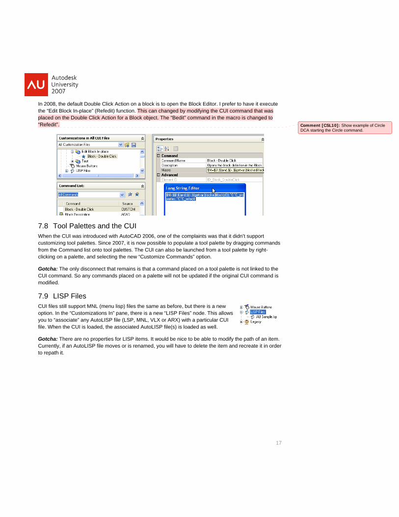
7.7 Double Click Actions e Double Click Action controls the event that occuk Action can be named anything, but it has to
uble
Menu. The “Object Name” must reflect the proper “dxfname” of object you are double-clicking on. For a fairly comprehensive of objects and their dxfnamions node in the ACAD.cui.
16
17
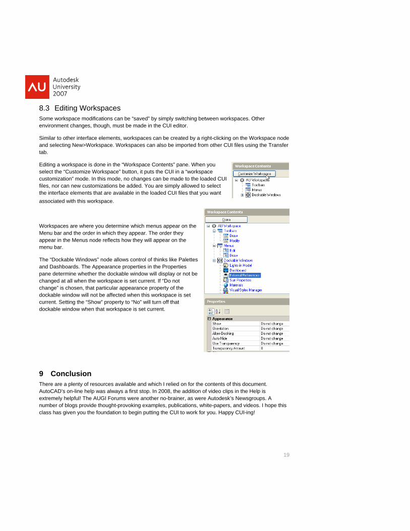
In 2008, the default Double Click Action on a block is to open the Block Editor. I prefer to have it execute the “Edit Block In-place” (Refedit) function. This can changed by modifying the CUI command that was placed on the Double Click Action for a Block object. The “Bedit” command in the macro is changed to “Refedit”.
7.8 Tool Palettes and the CUI When the CUI was introduced with AutoCAD 2006, one of the complaints was that it didn’t support customizing tool palettes. Since 2007, it is now possible to populate a tool palette by dragging commands from the Command list onto tool palettes. The CUI can also be launched from a tool palette by right-clicking on a palette, and selecting the new “Customize Commands” option.
Gotcha: The only disconnect that remains is that a command placed on a tool palette is not linked to the pdated if the original CUI command is
7.9CUI optiyou file. Wh
GotCurto re
CUI command. So any commands placed on a palette will not be umodified.
LISP Files files still support MNL (menu lisp) files the same as before, but there is a new
on. In the “Customizations In” pane, there is a new “LISP Files” node. This allows to “associate” any AutoLISP file (LSP, MNL, VLX or ARX) with a particular CUI
en the CUI is loaded, the associated AutoLISP file(s) is loaded as well.
Comment [CSL10]: ShowDCA starting the Circle com
example of Circle mand.
cha: There are no properties for LISP items. It would be nice to be able to modify the path of an item. rently, if an AutoLISP file moves or is renamed, you will have to delete the item and recreate it in order path it.

8 Workspaces Workspaces are one of those new CUI concepts that take a while to sink in. It’s not a critical concept when first getting into the CUI, but is not something that should be ignored either. Essentially, a
nsisting of a combination of interface elements (toolbars, menus,
8.1Evecom
• Workspaces define what interface elements are visible. It is essentially a way to streamline your ars, menu, palettes, etc. Changing workspaces changes how much of them you actually see.
all about the organization of the AutoCAD environment.
workspace is a named environment coetc.).
Workspaces vs Profiles ryone new to the CUI wrestles with the distinction between workspaces and profiles. Here is a brief parison:
“AutoCAD desktop”, eliminating unneeded toolbdoes not change which CUIs are loaded, it just
• Profiles contain what CUIs are loaded, but do not control what parts of the CUI are visible. Many of the settings controlled by a profile are invisible to the user (system settings, etc.), whereas a workspace is
8.2 Working with Workspaces Sometimes an example is worth a thousand words. The “acadSampleWorkspaces.cui” file that ships with AutoCAD has some nice pre-configured workspaces to give us an introduction. It must be designated as the Main or Enterprise customization file in order to use the workspaces defined in it. Once you get the general idea of what a Workspace is,
18
then
fined he current
inte
The
you can begin to modify them or create you own.
The Workspaces toolbar is central to choosing and managing workspaces. It contains a drop-down for switching between deworkspaces. With the “Save Current As” option you can save t
Comment [CSL11]: The win this example CUI are “tcould easily be client, project or
orkspaces defined ask” related, but they
discipline related.
rface configuration so that it can be restored later by name.
Workspace Settings icon on the toolbar displays the Workspace tings dialog for general management of workspaces. In dialog box, you control existing workspaces. The “My rkspace” value can be used to choose a “default” or
SetthisWopreferred workspace which can easily pick
be restored bying the icon on the Workspaces toolbar.
Menu Display and Order box controls which kspaces should be visible and in what order they uld appear in the list. So, it is possible to have more
The worshoworkspaces defined than are actively being used.
Wh seautocurrchawor
en switching workspaces, you can choo to matically save any environment changes to the ent workspace. If the “Do not save” option is chosen, nges will be lost when you switch to a different kspace.
19
8.3 Editing Workspaces Some workspace modifications can be “saved” by simply switching between workspaces. Other environment changes, though, must be made in the CUI editor.
n be created by a right-clicking on the Workspace node andtab.
Editing a workspace is done in the “Workspace Contents” pane. When you selecusfilesthe interface elements that are available in the loaded CUI files that you want associated w
WoMenappmen
The “Dockable Windows” node allows control of thinks like Palettes and ashboards. The Appearance properties in the Properties pane determine whether the dockable window will display or not be chachadoccurrdoc hen that workspace is set current.
9 The this doAut ideo clips in the Hextremely helpful! The AUGI Forums were another no-brainer, as were Autodesk’s Newsnumber of blogs provide thought-provoking examples, publications, white-papers, and vidclass has given you the foundation to begin putting the CUI to work for you. Happy CUI-ing
Similar to other interface elements, workspaces ca selecting New>Workspace. Workspaces can also be imported from other CUI files using the Transfer
ct the “Customize Workspace” button, it puts the CUI in a “workspace tomization” mode. In this mode, no changes can be made to the loaded CUI , nor can new customizations be added. You are simply allowed to select
ith this workspace.
rkspaces are where you determine which menus appear on the u bar and the order in which they appear. The order they ear in the Menus node reflects how they will appear on the u bar.
D
nged at all when the workspace is set current. If “Do not nge” is chosen, that particular appearance property of the kable window will not be affected when this workspace is set ent. Setting the “Show” property to “No” will turn off that kable window w
Conclusion re are a plenty of resources available and which I relied on for the contents of oCAD’s on-line help was always a first stop. In 2008, the addition of v
cument. elp is
groups. A eos. I hope this
!