Embed Size (px)
Citation preview
MMT CONVERSION
Doc.No. : D00001 Issue : 3 Date : January 1997
Steward Observatory
Technical Report #31
SECONDARY MIRRORS SUPPORT
M2/F15 and M2/F9 HEXAPOD DESIGN
W. Gallieni, R. Pozzi
ADS ITALIA Srl - Corso Promessi Sposi, 23/d - 22053 Lecco - ITALY Steward Observatory - University of Arizona - 933 N. Cherry Ave., Tucson Arizona 85721 - USA

MMT CONVERSION
Doc.No : D00001 Issue : 3 Date : January 1997
1 Applicable Documents 1.1 Optical scheme and secondary hub position as per attached diagram transmitted
by P. Gray with the order. 1.2 F9 secondary dimensions, including support and cooling system as per P. Gray’s
dwg. “sec_f9mmt.” 1.3 Preliminary figures of masses to be supported and positioned: For F/9 see the enclosed budget evaluation by P. Gray. For F/15 see the preliminary estimation from the Arcetri “Preliminary Technical
Report December 1995.” 1.4 Hexapod technical characteristics as per the tentative specification by P. Gray—S.
West attached to the order.
Page 2
ADS ITALIA Srl - Corso Promessi Sposi, 23/d - 22053 Lecco - ITALY Steward Observatory - University of Arizona - 933 N. Cherry Ave., Tucson Arizona 85721 - USA
MMT CONVERSION
Doc.No : D00001 Issue : 3 Date : January 1997
2 Design Strategy Taking into account the dimensional constraints imposed by the existing center hub, the development of the design activity has been organized as follows: A. Rough max. load evaluation per actuator: ±128÷97 kg - Travel ±10 mm
B. Components preliminary selection: - Roller screw 20 mm, lead 1÷2 mm
- Motor Inland type RBE-01506
max. cont. stall torque 1,12 Nm
- Brake Electroid type MFSB 26
rated static torque 3,4 Nm
- Encoder Heidenhain ERO1325
2000 cts/rev
C. Actuator preliminary assembly drawing: length = 376 mm between end of flexure
joints.
D. Hexapod base geometry: Dwg. a200513 (attached at end of report).
E. FEA model and calculation of force distribution between zenith and horizon
pointing for F/15 AND F/9.
F. Final verification of the selected components and definition of preloads and max.
Forces.
G. Analysis of the system dynamic for verifying the max. angular displacement of the
flexure joints at the limit of ± 10 mm displacement.
H. Updating of the F/15 general assembly dwg. redistributing volume inside the
center hub. See dwg. a300931 (attached at end of report).
I. First comparative assembly of the F/9 support with the same hexapod dimensions
of F/15. See Item H.
J. Updating of the FEA model and first dynamic analysis with infinite stiff center hub
constraints.
Page 3
ADS ITALIA Srl - Corso Promessi Sposi, 23/d - 22053 Lecco - ITALY Steward Observatory - University of Arizona - 933 N. Cherry Ave., Tucson Arizona 85721 - USA
MMT CONVERSION
Doc.No : D00001 Issue : 3 Date : January 1997
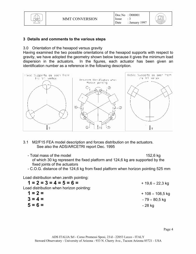
3 Details and comments to the various steps 3.0 Orientation of the hexapod versus gravity Having examined the two possible orientations of the hexapod supports with respect to gravity, we have adopted the geometry shown below because it gives the minimum load dispersion in the actuators. In the figures, each actuator has been given an identification number as a reference in the following description.
3.1 M2/F15 FEA model description and forces distribution on the actuators. See also the ADS/ARCETRI report Dec. 1995 - Total mass of the model 152,6 kg of which 30 kg represent the fixed platform and 124,6 kg are supported by the
fixed joints of the actuators - C.O.G. distance of the 124,6 kg from fixed platform when horizon pointing 525 mm Load distribution when zenith pointing: 1 = 2 = 3 = 4 = 5 = 6 = + 19,6 ÷ 22,3 kg Load distribution when horizon pointing: 1 = 2 = + 108 ÷ 108,5 kg 3 = 4 = - 79 ÷ 80,5 kg 5 = 6 = - 28 kg
Page 4
ADS ITALIA Srl - Corso Promessi Sposi, 23/d - 22053 Lecco - ITALY Steward Observatory - University of Arizona - 933 N. Cherry Ave., Tucson Arizona 85721 - USA
MMT CONVERSION
Doc.No : D00001 Issue : 3 Date : January 1997
3.2 M2/F9 FEA model description and forces distribution on the actuators. Mirror, support, and ventilation system mass and c.o.g. according to P. Gray document dated 9/26/95, revised 9/27/95 - Total mass of the model 215 kg of which 200,4 kg applied to the fixed joints and 14,6 kg own mass of fixed
platform. - C.O.G. distance of the 200,4 kg from fixed platform when horizon pointing 410 mm The 200,4 kg are to be divided between 161,7 kg for the M2 and its accessories,
and 38,7 kg for hexapod with mobile plate and supports. Load distribution when zenith pointing: 1 = 2 = 3 = 4 = 5 = 6 = + 36,7 kg Load distribution when horizon pointing: 1 = 2 = + 143 ÷ 144 kg 3 = 4 = - 134 ÷ 135 kg 5 = 6 = - 9,3 kg N.B.: The values induced by the F/9 configuration are the one to be used for the actuators components final verification 3.3 Angular displacement and Flexure Joints dimensioning 3.3.1 A dynamic analysis of the hexapod has been performed for pointing inside the limit displacements requested by the specification to solve for the angular displacements of the actuators joints. The analysis was based on the hexapod geometry, dwg. a200513, with the following results: Focusing ± 10 mm max. joint angular displacement ± 0,5 degrees x, y lateral displacement ± 5 mm “ “ “ “ ± 0,6 “ Tilt of M2 around its vertex within a cone having 1° semiaperture “ “ “ “ ± 1,0 “ For a given focusing motion, the change in actuator length is smaller ( ±8,5 mm for ±10 mm focusing ). This is because the hexapod consists of a 3 isosceles trapezium with its upper and lower bases invariant. This can be seen in the figures in section 3.0. 3.3.2 Flexure Joint dimensioning
Page 5
ADS ITALIA Srl - Corso Promessi Sposi, 23/d - 22053 Lecco - ITALY Steward Observatory - University of Arizona - 933 N. Cherry Ave., Tucson Arizona 85721 - USA
MMT CONVERSION
Doc.No : D00001 Issue : 3 Date : January 1997
The exigencies of the present optimization study are various and in conflict with each other, so an extensive study of FEA models has been performed to derive a well balanced compromise design. The parameters we have considered are: a ) Stiffness: Its value increases linearly with the flexure cross section, while it decreases linearly with the flexure height. Each joint consists of two flexures in series, rotated by 90° with respect to each other, and the efficiency of the adopted section depends upon the thickness of the interposed disc for a uniform distribution of the transmitted load. The flexure height is to be compromised between the bending stress caused by the max. deflection angle and the stiffness, values that change in inverse proportion with the height. b ) Overall length of the actuator: We have tried to minimize this parameter for the constraint represented by the existing center hub dimensions, so this is the third parameter to be considered in the compromise design solution under discussion. At the conclusion of the optimization work described in the enclosed document of R. Pozzi, we decided to introduce the following dimensions into the final design of the actuator: Thickness of the flexure 0,4 mm Flexure width 35÷40 mm Flexure height 4.0 mm Intermediate disc thickness 5,0 mm One single joint stiffness 21,95 daN / µ Note: 10 N = 1 daN Convention is used in Italy and Germany, and is essentially equivalent to Kg force.
Page 6
ADS ITALIA Srl - Corso Promessi Sposi, 23/d - 22053 Lecco - ITALY Steward Observatory - University of Arizona - 933 N. Cherry Ave., Tucson Arizona 85721 - USA
MMT CONVERSION
Doc.No : D00001 Issue : 3 Date : January 1997
4 Verification of the selected components 4.1 Roller Screw Selected a ROLLVIS Satellite Roller Screw, type: RVR 20 X 1 - nominal diameter d 0 = 20 mm - lead 1 mm Dynamic load rating 8,13 KN - Static load rating 12,1 KN Nut Stiffness = 40 kg / µ Screw Stiffness (length 60 mm) = 164 / 9,81 . d o² / l = 16,71 . 202 / 60 = 111 kg / µ Efficiency (fig. 6 of catalogue) η1= 0,72 - force direction opposite to movement η2 = 0,61- force direction in movement direction - Axial loads on the screw nut: Zenith pointing + 360 N Horizon pointing + 1415 N ÷ - 1325 N - Minimum preload to be applied to the nut: Fpr = 1415 / 2,83 =500 N Selected Value = 600 N - Torque due to preload:
Tpr = Fpr . lead/2.π.(1/η1 .0,9 - η2) = 600.1/2. π.(1/0,72.0,9 - 0,61) = 89,1 N.mm Tpr = 0,089 Nm - Backdrive torque, max. for brake verification: Tbkd = F.p / 2.π . η2 = (1415.1 / 2.π) . 0,61 = 137 Nmm = 0,137 Nm - Demanded torque for lifting: Tlif min = 360.1 / 2000.π. η1 = 360 / 2000.π.0,72 = 0,0795 Nm Tlifmax = 1415.1 /2000.π.η1 = 1415 / 2000.µ.0,72 = 0,313 Nm - Demanded torque for lowering:
Tlow min = 360.1.η2 / 2000.π = 360.0,61 / 2000. π = 0,035 Nm Tlow max = 1415.1. η2 / 2000.π = 1415.0,61 / 2000. π = 0,137 Nm
- Demanded torque for accelerating the rotating masses: Considering the extremely small value of the specified axial speed, - 0,5 mm / sec =
30 rpm of the motor, the angular acceleration is very small, and the accelerating torque can be neglected in the balance of the max. torque demanded to the motor.
4.2 DC Brushless Motor Considering the reduction of requested torque following the adoption of a screw lead of 1 mm, we reconsidered the type of motor to use, also basing the choice on the new Inland catalogue, and selected the type: - Brushless servomotor RBE(H) Series, type 01514 - Continuous Stall Torque 0,818 Nm - Peak Torque 2,57 Nm that also has the advantage of being 18 mm shorter than the first selected.
Page 7
ADS ITALIA Srl - Corso Promessi Sposi, 23/d - 22053 Lecco - ITALY Steward Observatory - University of Arizona - 933 N. Cherry Ave., Tucson Arizona 85721 - USA
MMT CONVERSION
Doc.No : D00001 Issue : 3 Date : January 1997
4.3 Brake selection For the same above considerations and according to the Supplier suggestions, we now select the Electroid Failsafe brake of the EFSB Series: Type EFSB15 - rated static torque 1,7 Nm that has the advantage of having an outside diameter 1 inch smaller than the first selected. 4.4 Incremental Encoder selection According to the US representative’s suggestion, we agree in selecting a Heidenhain Incremental Encoder Type ERO 1324 - 5000 cts / rev, that gives, assembled in axis to a 1 mm lead screw, a resolution of 1000 / 5000 = 0,2 µm / count. 4.5 Axis Moment of Inertia Just for more accurate calculations, listed below are the various components of the system: Encoder 20.E-6 kg.m² Brake 3,5.E-6 kg.m² Motor 54,4.E-6 kg.m² Roller nut 0,8.E-6 kg.m² Screw (l= 0,2 m) 0,2.E-6 kg.m² TOTAL 78,9.e-6 kg.m² 4.6 Present configuration of the actuators According to dwg. a200505 (attached at end of report) and detailed dwgs., the computation of the actuator axial stiffness comes from: A) Items 01, 02, 03, 04 ⇒ L = 110 mm, Φe = 90 mm, Φi = 78 mm, Aluminum B) Item 08 ⇒ L = 35 mm, Φe = 84 mm, Φi = 70 mm, Steel C) Item 08 ⇒ L = 35 mm, Φe = 80 mm, Φi = 42 mm, Steel D) Item 100 ⇒ L = 20 mm, Φe = 19 mm, Steel E) Items 13, 15, 21, ⇒ L = 81 mm, Φe = 58 mm, Φi = 34 mm, Aluminum Note that items 01 and 21 do not consider the joints themselves, which are counted separately. For their stiffness values see Annexe 1 . For the commercial items, such as nut screw and bearings, the stiffness rates come from the supplier. The single values of axial stiffness are:
Page 8
ADS ITALIA Srl - Corso Promessi Sposi, 23/d - 22053 Lecco - ITALY Steward Observatory - University of Arizona - 933 N. Cherry Ave., Tucson Arizona 85721 - USA
MMT CONVERSION
Doc.No : D00001 Issue : 3 Date : January 1997
A) = 1.008E+5 daN/mm B) = 1.016E+6 daN/mm C) = 2.185E+6 daN/mm D) = 1.49E+5 daN/mm E) = 2.97E+5 daN/mm Joint = 2.2E4 daN/mm Nut = 4.0E+4 daN/mm Bearings = 9.3E+3 daN/mm The overall stiffness of the actuator is Kax = 4080 daN/mm ⇒ Kax = 4 daN/µm From this value comes the cross sectional area—equal for each beam element adopted for the FEA—which is: A = Kax x L / E = 4000 x 330 / 21000 ≈ 63 mm2 The mean weight density is: γ = P / A x L = 5 / 63 x 330 = 2.405E-4 daN/mm3 The torsional and flexural moments of inertia are computed from the diameters’ value listed previously.
Page 9
ADS ITALIA Srl - Corso Promessi Sposi, 23/d - 22053 Lecco - ITALY Steward Observatory - University of Arizona - 933 N. Cherry Ave., Tucson Arizona 85721 - USA
MMT CONVERSION
Doc.No : D00001 Issue : 3 Date : January 1997
ANNEXE 1
ABOUT “MMT” HEXAPOD FLEXURAL JOINT Here is a memorandum of different finite element models describing the process followed to determine the suggested configuration of the M2-Hexapod flexural joint for the MMT conversion. A single joint consists of two orthogonally spaced rectangular foils interconnected by a disk; the “fixed” and the “movable” ends of the foils end with a similar disk—the first is connected to ground and the second to the actuator’s body. The thickness of these two disks was set to 10 mm. The geometrical parameters of the joint examined are: for the foil: - height - thickness - width for the inner disk: - thickness - diameter (equal to foil width) The foils are modeled with 4-node shell elements, and the disks with 8-node brick elements with radial symmetry. From earlier considerations, we noted that stresses arose to unpredictable values with the foils crossed and intersected; therefore, in all these models the foils do not have any direct contact point or line, but end at the inner disk surface. By avoiding numerical instability at the lines where disks and foils meet, the disks (all of them) have a 1 mm radius fillet. This geometrical configuration is also similar to the joint to be machined. The goal of these simulations is to determine a joint configuration with the highest axial stiffness with the lowest stresses. Therefore, for each examined configuration, axial stiffness and stresses are reported. The axial stiffness is referred to a single joint model, whereas the working stress (measured for different angular displacements) is referred to a complete actuator model. It consists of two twin joints and a rod—beam element modeled—connecting them; the angular displacement was converted to linear displacement—via the length of the actuator—imposed at one end. The final configuration was also examined subject to the working loads previously determined on a complete hexapod FEA model. The iteration performed on the geometrical parameters are so grouped:
Page 10
ADS ITALIA Srl - Corso Promessi Sposi, 23/d - 22053 Lecco - ITALY Steward Observatory - University of Arizona - 933 N. Cherry Ave., Tucson Arizona 85721 - USA
MMT CONVERSION
Doc.No : D00001 Issue : 3 Date : January 1997
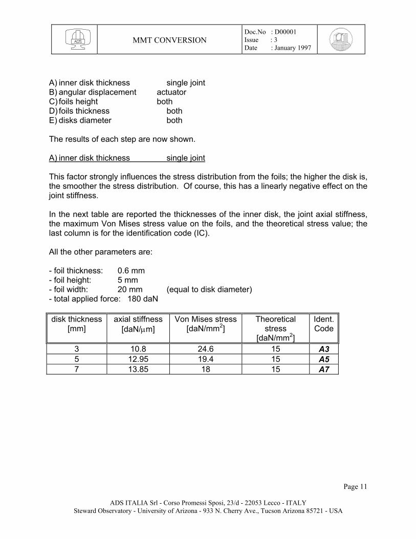
A) inner disk thickness single joint B) angular displacement actuator C) foils height both D) foils thickness both E) disks diameter both The results of each step are now shown. A) inner disk thickness single joint This factor strongly influences the stress distribution from the foils; the higher the disk is, the smoother the stress distribution. Of course, this has a linearly negative effect on the joint stiffness. In the next table are reported the thicknesses of the inner disk, the joint axial stiffness, the maximum Von Mises stress value on the foils, and the theoretical stress value; the last column is for the identification code (IC). All the other parameters are: - foil thickness: 0.6 mm - foil height: 5 mm - foil width: 20 mm (equal to disk diameter) - total applied force: 180 daN disk thickness
[mm] axial stiffness
[daN/µm] Von Mises stress
[daN/mm2] Theoretical
stress [daN/mm2]
Ident. Code
3 10.8 24.6 15 A3 5 12.95 19.4 15 A5 7 13.85 18 15 A7
Page 11
ADS ITALIA Srl - Corso Promessi Sposi, 23/d - 22053 Lecco - ITALY Steward Observatory - University of Arizona - 933 N. Cherry Ave., Tucson Arizona 85721 - USA
MMT CONVERSION
Doc.No : D00001 Issue : 3 Date : January 1997
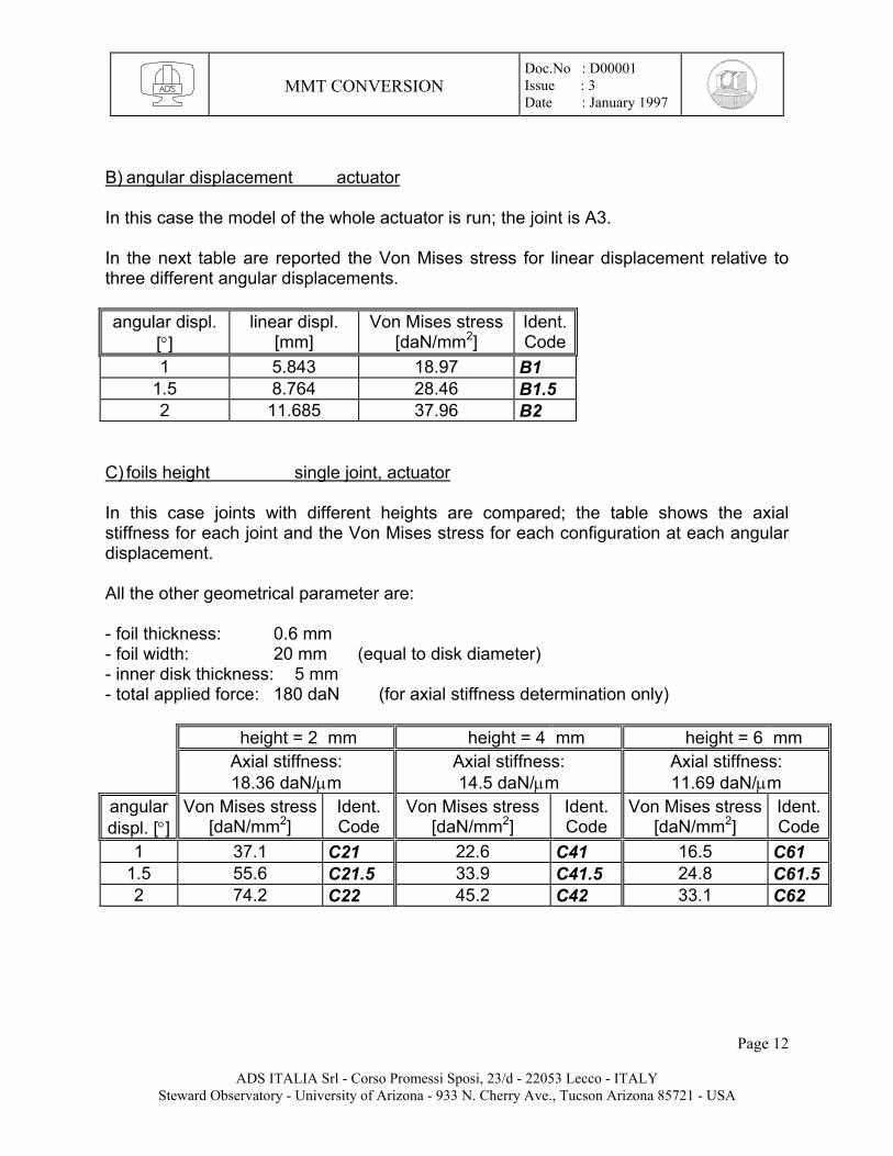
B) angular displacement actuator In this case the model of the whole actuator is run; the joint is A3. In the next table are reported the Von Mises stress for linear displacement relative to three different angular displacements. angular displ.
[°] linear displ.
[mm] Von Mises stress
[daN/mm2] Ident.Code
1 5.843 18.97 B1 1.5 8.764 28.46 B1.5 2 11.685 37.96 B2
C) foils height single joint, actuator In this case joints with different heights are compared; the table shows the axial stiffness for each joint and the Von Mises stress for each configuration at each angular displacement. All the other geometrical parameter are: - foil thickness: 0.6 mm - foil width: 20 mm (equal to disk diameter) - inner disk thickness: 5 mm - total applied force: 180 daN (for axial stiffness determination only)
height = 2 mm height = 4 mm height = 6 mm Axial stiffness:
18.36 daN/µm Axial stiffness: 14.5 daN/µm
Axial stiffness: 11.69 daN/µm
angular displ. [°]
Von Mises stress [daN/mm2]
Ident. Code
Von Mises stress [daN/mm2]
Ident. Code
Von Mises stress[daN/mm2]
Ident.Code
1 37.1 C21 22.6 C41 16.5 C61 1.5 55.6 C21.5 33.9 C41.5 24.8 C61.52 74.2 C22 45.2 C42 33.1 C62
Page 12
ADS ITALIA Srl - Corso Promessi Sposi, 23/d - 22053 Lecco - ITALY Steward Observatory - University of Arizona - 933 N. Cherry Ave., Tucson Arizona 85721 - USA
MMT CONVERSION
Doc.No : D00001 Issue : 3 Date : January 1997
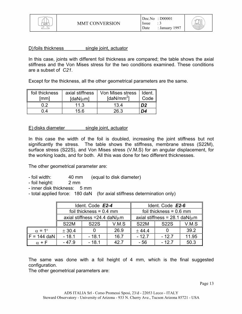
D) foils thickness single joint, actuator In this case, joints with different foil thickness are compared; the table shows the axial stiffness and the Von Mises stress for the two conditions examined. These conditions are a subset of C21. Except for the thickness, all the other geometrical parameters are the same. foil thickness
[mm] axial stiffness
[daN/µm] Von Mises stress
[daN/mm2] Ident.Code
0.2 11.3 13.4 D2 0.4 15.6 26.3 D4
E) disks diameter single joint, actuator In this case the width of the foil is doubled, increasing the joint stiffness but not significantly the stress. The table shows the stiffness, membrane stress (S22M), surface stress (S22S), and Von Mises stress (V.M.S) for an angular displacement, for the working loads, and for both. All this was done for two different thicknesses. The other geometrical parameter are: - foil width: 40 mm (equal to disk diameter) - foil height: 2 mm - inner disk thickness: 5 mm - total applied force: 180 daN (for axial stiffness determination only)
Ident. Code E2-4 Ident. Code E2-6 foil thickness = 0.4 mm foil thickness = 0.6 mm axial stiffness =24.4 daN/µm axial stiffness = 28.1 daN/µm S22M S22S V.M.S S22M S22S V.M.S
α = 1° ± 30.4 0 26.9 ± 44.4 0 39.2 F = 144 daN - 18.1 - 18.1 16.7 - 12.7 - 12.7 11.95
α + F - 47.9 - 18.1 42.7 - 56 - 12.7 50.3 The same was done with a foil height of 4 mm, which is the final suggested configuration. The other geometrical parameters are:
Page 13
ADS ITALIA Srl - Corso Promessi Sposi, 23/d - 22053 Lecco - ITALY Steward Observatory - University of Arizona - 933 N. Cherry Ave., Tucson Arizona 85721 - USA
MMT CONVERSION
Doc.No : D00001 Issue : 3 Date : January 1997
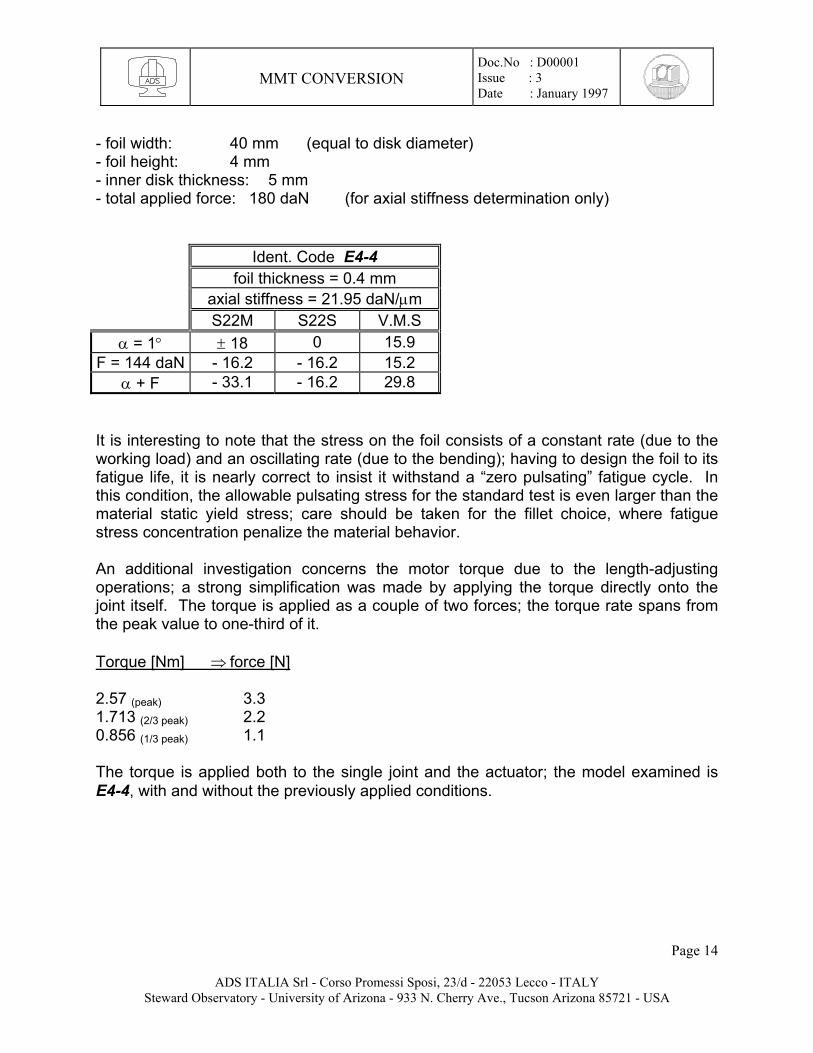
- foil width: 40 mm (equal to disk diameter) - foil height: 4 mm - inner disk thickness: 5 mm - total applied force: 180 daN (for axial stiffness determination only)
Ident. Code E4-4 foil thickness = 0.4 mm axial stiffness = 21.95 daN/µm S22M S22S V.M.S
α = 1° ± 18 0 15.9 F = 144 daN - 16.2 - 16.2 15.2
α + F - 33.1 - 16.2 29.8 It is interesting to note that the stress on the foil consists of a constant rate (due to the working load) and an oscillating rate (due to the bending); having to design the foil to its fatigue life, it is nearly correct to insist it withstand a “zero pulsating” fatigue cycle. In this condition, the allowable pulsating stress for the standard test is even larger than the material static yield stress; care should be taken for the fillet choice, where fatigue stress concentration penalize the material behavior. An additional investigation concerns the motor torque due to the length-adjusting operations; a strong simplification was made by applying the torque directly onto the joint itself. The torque is applied as a couple of two forces; the torque rate spans from the peak value to one-third of it. Torque [Nm] ⇒ force [N] 2.57 (peak) 3.3 1.713 (2/3 peak) 2.2 0.856 (1/3 peak) 1.1 The torque is applied both to the single joint and the actuator; the model examined is E4-4, with and without the previously applied conditions.
Page 14
ADS ITALIA Srl - Corso Promessi Sposi, 23/d - 22053 Lecco - ITALY Steward Observatory - University of Arizona - 933 N. Cherry Ave., Tucson Arizona 85721 - USA
MMT CONVERSION
Doc.No : D00001 Issue : 3 Date : January 1997
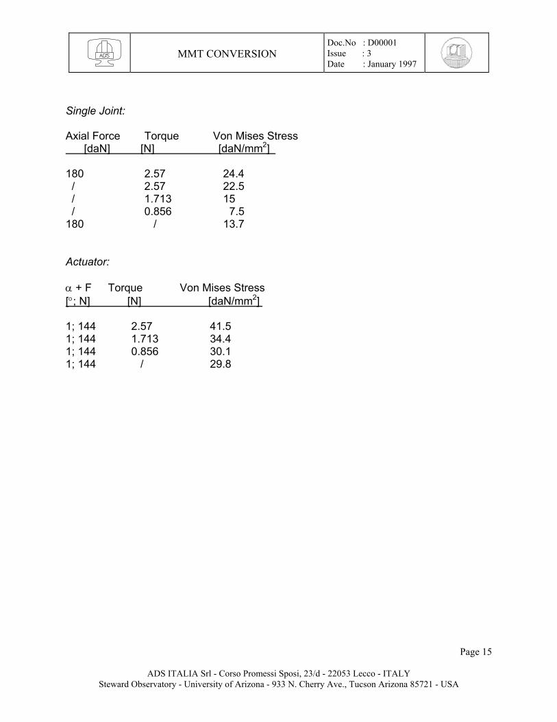
Single Joint: Axial Force Torque Von Mises Stress [daN] [N] [daN/mm2] 180 2.57 24.4 / 2.57 22.5 / 1.713 15 / 0.856 7.5 180 / 13.7 Actuator: α + F Torque Von Mises Stress [°; N] [N] [daN/mm2] 1; 144 2.57 41.5 1; 144 1.713 34.4 1; 144 0.856 30.1 1; 144 / 29.8
Page 15
ADS ITALIA Srl - Corso Promessi Sposi, 23/d - 22053 Lecco - ITALY Steward Observatory - University of Arizona - 933 N. Cherry Ave., Tucson Arizona 85721 - USA
MMT CONVERSION
Doc.No : D00001 Issue : 3 Date : January 1997
ANNEXE 2
MMT CONVERSION - HEXAPOD FOR M2 This report refers to the dynamic simulation of the M2F9 and M2F15 hexapod system for the MMT conversion for the actuator configuration shown in dwg. a200505 and accompanying detailed dwgs.
M2F15 CONFIGURATION For the geometrical configurations of this scheme see dwg. a300931. The data for the actuator are: - length: 330 mm - weight: 5 daN - axial stiffness: 4 daN/µm (joints included) - Young Modulus: 21000 daN/mm2 - weight density: 2.405E-4 daN/mm3 The F.E. model consists of: item element type weight [daN] - hub shell 170.7 - hexapod beam 30 - hexapod interface beam, shell 21.3 - mirror support interface beam, shell 31.8 - mirror brick 49.5 The optical system—consisting of the hexapod, hexapod interface, mirror support interface, and mirror—weighs 132.6 daN The complete system—consisting of optical system and hub—weighs 303.3 daN.
Page 16
ADS ITALIA Srl - Corso Promessi Sposi, 23/d - 22053 Lecco - ITALY Steward Observatory - University of Arizona - 933 N. Cherry Ave., Tucson Arizona 85721 - USA
MMT CONVERSION
Doc.No : D00001 Issue : 3 Date : January 1997
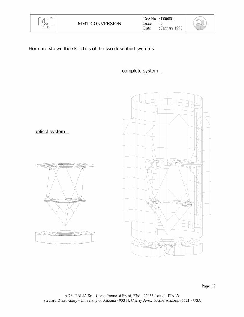
Here are shown the sketches of the two described systems.
complete system optical system
Page 17
ADS ITALIA Srl - Corso Promessi Sposi, 23/d - 22053 Lecco - ITALY Steward Observatory - University of Arizona - 933 N. Cherry Ave., Tucson Arizona 85721 - USA

MMT CONVERSION
Doc.No : D00001 Issue : 3 Date : January 1997
The frequencies and the mode shapes for the Optical System, fixed on ground at the upper actuator support, are: # Freq. [Hz] mode shape 1) 40.8 twist around focal axis 2) 43.07 I° lateral deflection (pendulum mode) 3) 43.3 I° lateral deflection 4) 133 II° lateral deflection 5) 133 II° lateral deflection The frequencies and the mode shapes for the Complete System fixed on ground at eight points where the spider vanes attach to the fixed hub, are: # Freq. [Hz] mode shape 1) 39.1 Optical System I° lateral deflection 2) 39.8 Optical System I° lateral deflection 3) 41.2 Optical System twist around focal axis 4) 127.0 Optical System II° lateral deflection 5) 127.5 Optical System II° lateral deflection
Page 18
ADS ITALIA Srl - Corso Promessi Sposi, 23/d - 22053 Lecco - ITALY Steward Observatory - University of Arizona - 933 N. Cherry Ave., Tucson Arizona 85721 - USA
MMT CONVERSION
Doc.No : D00001 Issue : 3 Date : January 1997
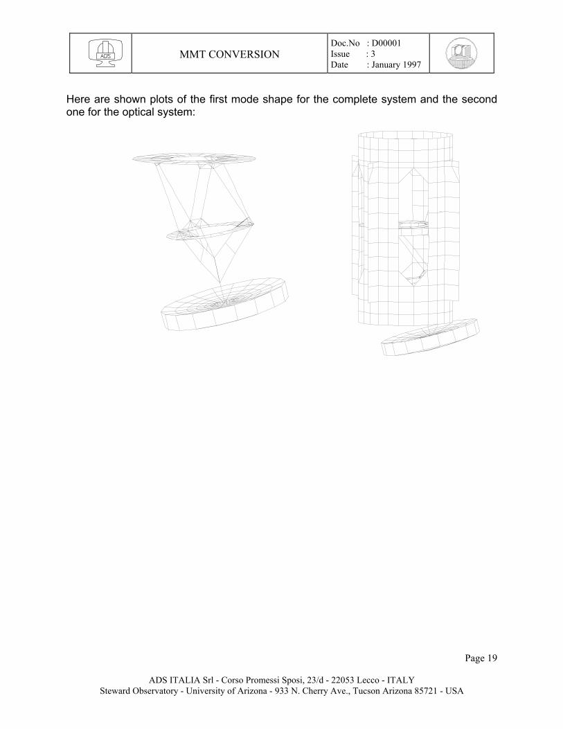
Here are shown plots of the first mode shape for the complete system and the second one for the optical system:
Page 19
ADS ITALIA Srl - Corso Promessi Sposi, 23/d - 22053 Lecco - ITALY Steward Observatory - University of Arizona - 933 N. Cherry Ave., Tucson Arizona 85721 - USA
MMT CONVERSION
Doc.No : D00001 Issue : 3 Date : January 1997
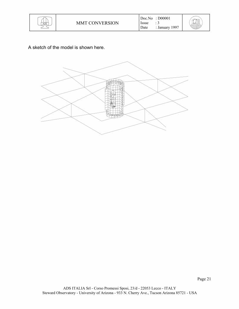
In these next steps, the static and dynamic behaviors of the complete system supported by the spider vanes, here defined as Whole System, are shown. The spiders are described by adopting beam elements with the geometrical and cross-sectional features as seen from “S-2” and “S-3” MMT dwgs. They weigh 184 daN. The beams’ ends connecting to the telescope top ring are modeled fixed on ground, which is considered to have infinite stiffness. The beams are modeled in one single element between each crossing in order to hide their local modes from the structural modes of the Whole System; this trick obtains the structural eigenfrequencies without requiring the running of nearly 60-70 modes—most of which are local modes of the spiders. Of course, even if not listed, the local modes do occur. The Whole System weighs 487 daN. The first step is to apply preload forces able to induce the required tension loads of 10,000 daN at each upper strap, and 11,000 daN at each lower strap of the spiders. This has been accomplished by applying two differential temperature sets of -370°C at the upper straps and +120°C to the lower ones. Including the weight of the structure, the tension loads which best approximate the required value—note that the structure is strongly hyperstatic—are: Fupper = 8979 daN, Flower = 11550 daN, and the mirror vertex displacement is ∆z = -62 mm toward the primary mirror.
Page 20
ADS ITALIA Srl - Corso Promessi Sposi, 23/d - 22053 Lecco - ITALY Steward Observatory - University of Arizona - 933 N. Cherry Ave., Tucson Arizona 85721 - USA
MMT CONVERSION
Doc.No : D00001 Issue : 3 Date : January 1997
A sketch of the model is shown here.
Page 21
ADS ITALIA Srl - Corso Promessi Sposi, 23/d - 22053 Lecco - ITALY Steward Observatory - University of Arizona - 933 N. Cherry Ave., Tucson Arizona 85721 - USA
MMT CONVERSION
Doc.No : D00001 Issue : 3 Date : January 1997
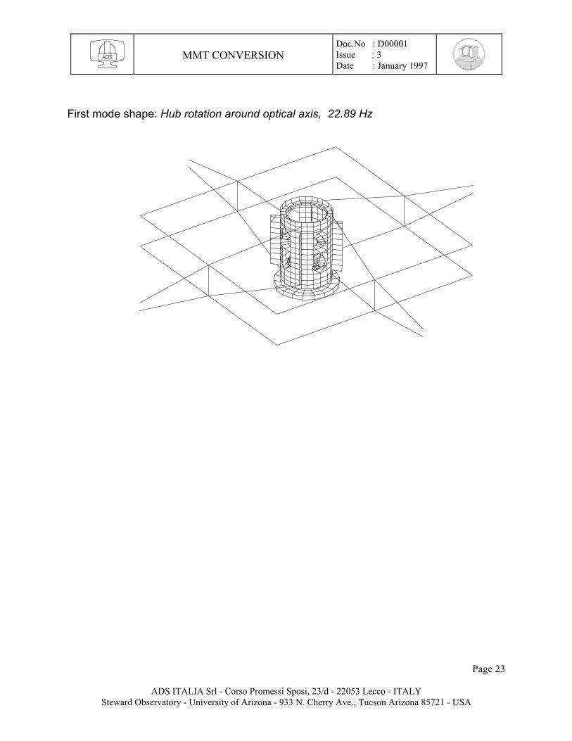
The frequency behavior of the system without tensile preloads is: # Freq. [Hz] mode shape 1) 3.36 hub rotation around optical axis 2) 22.97 hub piston mode 3) 32.92 hexapod lateral + spider local 4) 33.02 hexapod lateral + spider local 5) 33.52 spider local The frequency behavior of the system with tensile preloads is: # Freq. [Hz] mode shape 1) 22.89 hub rotation around optical axis 2) 23.45 hub piston mode 3) 34.76 hexapod lateral + spider local 4) 34.85 hexapod lateral + spider local 5) 38.26 spider local Next follow plots of the deformed mode shapes.
Page 22
ADS ITALIA Srl - Corso Promessi Sposi, 23/d - 22053 Lecco - ITALY Steward Observatory - University of Arizona - 933 N. Cherry Ave., Tucson Arizona 85721 - USA
MMT CONVERSION
Doc.No : D00001 Issue : 3 Date : January 1997
First mode shape: Hub rotation around optical axis, 22.89 Hz
Page 23
ADS ITALIA Srl - Corso Promessi Sposi, 23/d - 22053 Lecco - ITALY Steward Observatory - University of Arizona - 933 N. Cherry Ave., Tucson Arizona 85721 - USA
MMT CONVERSION
Doc.No : D00001 Issue : 3 Date : January 1997
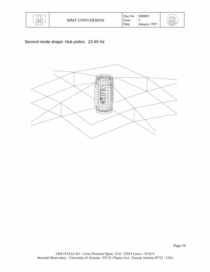
Second mode shape: Hub piston, 23.45 Hz
Page 24
ADS ITALIA Srl - Corso Promessi Sposi, 23/d - 22053 Lecco - ITALY Steward Observatory - University of Arizona - 933 N. Cherry Ave., Tucson Arizona 85721 - USA
MMT CONVERSION
Doc.No : D00001 Issue : 3 Date : January 1997
M2F9 CONFIGURATION
The geometrical configurations of this scheme are shown in dwg. a300930b (attached at end of report). The data for the actuator are the same as for the previous configuration. The F.E. model consists of: item element type weight [daN] - hub: shell 170.7 - hexapod interface shell 89.8 - hexapod beam 30 - lower, upper act. support beam 4.6 - interfaces support beam, shell 84.6 (*) - mirror brick 77 + 10 (*) The Optical system—consisting of the hexapod, upper and lower actuator support, interfaces support, and mirror—weighs 206.2 daN. The Complete system—consisting of optical system, hexapod interface and hub—weighs 466.7 daN.
Page 25
ADS ITALIA Srl - Corso Promessi Sposi, 23/d - 22053 Lecco - ITALY Steward Observatory - University of Arizona - 933 N. Cherry Ave., Tucson Arizona 85721 - USA
MMT CONVERSION
Doc.No : D00001 Issue : 3 Date : January 1997
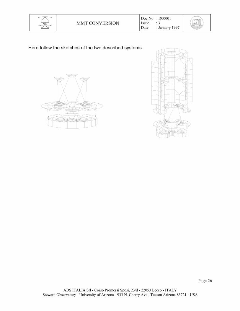
Here follow the sketches of the two described systems.
Page 26
ADS ITALIA Srl - Corso Promessi Sposi, 23/d - 22053 Lecco - ITALY Steward Observatory - University of Arizona - 933 N. Cherry Ave., Tucson Arizona 85721 - USA
MMT CONVERSION
Doc.No : D00001 Issue : 3 Date : January 1997
The weight distribution for the various components is: dead mass own weight added to. - Bellofram cyl. 10 daN mirror ( 10/2 ), interfaces support ( 10/2 ) - cylinders fixtures 10 daN mirror ( 10/2 ), interfaces support ( 10/2 ) - ventilation tubes 5 daN interfaces support - ventilation plenum 10 daN interfaces support - ventilation fan 10 daN interfaces support - mirror wall 20.3 daN interfaces support - backplate 29.3 daN interfaces support the overall weights are: - mirror: 77 + 10/2 +10/2 = 87 daN - interfaces support: 10/2 + 10/2 + 5 + 10 + 10 + 20.3 + 29.3 = 84.6
_______ The frequencies and the mode shapes for the Optical System, fixed on ground at the upper actuator support, are: # Freq. [Hz] mode shape 1) 40.26 I° lateral deflection 2) 40.57 I° lateral deflection 3) 69.36 hexapod twisting around optical axis 4) 105.9 II° lateral deflection 5) 108.3 II° lateral deflection The frequencies and the mode shapes for the Complete System, fixed on ground at eight points at the hub spiders’ attachment, are: # Freq. [Hz] mode shape 1) 39.09 Optical System I° lateral deflection 2) 39.38 Optical System I° lateral deflection 3) 68.25 Optical System twisting around optical axis 4) 105.1 Optical System II° lateral deflection 5) 107.3 Optical System II° lateral deflection
Page 27
ADS ITALIA Srl - Corso Promessi Sposi, 23/d - 22053 Lecco - ITALY Steward Observatory - University of Arizona - 933 N. Cherry Ave., Tucson Arizona 85721 - USA

MMT CONVERSION
Doc.No : D00001 Issue : 3 Date : January 1997
Here follow plots of the first mode shape:
Complete System: I° lateral. mode, 39.09 Hz Optical System: I° lateral. mode, 40.26 Hz
If we consider a hexapod interface made of aluminum instead of steel, its weight decreases from 89.8 daN to 30.9 daN. In such conditions the Optical System always weighs 206.2 daN; meanwhile the Complete System weighs 407.7 daN.
The frequencies and the mode shapes for the Complete System now are: # Freq. [Hz] mode shape 1) 37.68 Optical System I° lateral deflection 2) 37.92 Optical System I° lateral deflection 3) 67.58 Optical System twisting around optical axis 4) 104.0 external ribs local mode 5) 106.2 external ribs local mode
Page 28
ADS ITALIA Srl - Corso Promessi Sposi, 23/d - 22053 Lecco - ITALY Steward Observatory - University of Arizona - 933 N. Cherry Ave., Tucson Arizona 85721 - USA
MMT CONVERSION
Doc.No : D00001 Issue : 3 Date : January 1997
The following considerations from here apply only to the system with the hexapod interface made of aluminum. In these next steps, the static and dynamic behaviors of the complete system supported by the spiders, here defined as Whole System, are shown. The spiders are the same as described for M15; all the considerations seen before apply here as well. The Whole System weighs 592 daN. The first step is to apply preload forces to induce the required tension loads of 10,000 daN at each upper strap, and 11,000 daN at each lower strap of the spiders. This has been accomplished by applying two differential temperature sets of -370°C at the upper straps and +120°C to the lower ones. Including the weight of the structure, the tension loads which best approximate the required value—note that the structure is strongly hyperstatic—are: Fupper = 9020 daN ; Flower = 11680 daN and the mirror vertex displacement is ∆z = -62 mm toward the primary mirror. The frequency behavior of the system without tensile preloads is: # Freq. [Hz] mode shape 1) 2.9 hub rotation around optical axis 2) 21.9 hub piston mode 3) 33.59 spider local + Optical System I° lateral deflection 4) 33.66 spider local + Optical System I° lateral deflection 5) 33.67 spider local + Optical System I° lateral deflection
Page 29
ADS ITALIA Srl - Corso Promessi Sposi, 23/d - 22053 Lecco - ITALY Steward Observatory - University of Arizona - 933 N. Cherry Ave., Tucson Arizona 85721 - USA
MMT CONVERSION
Doc.No : D00001 Issue : 3 Date : January 1997
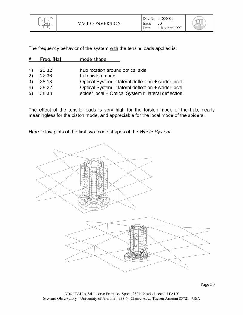
The frequency behavior of the system with the tensile loads applied is: # Freq. [Hz] mode shape 1) 20.32 hub rotation around optical axis 2) 22.36 hub piston mode 3) 38.18 Optical System I° lateral deflection + spider local 4) 38.22 Optical System I° lateral deflection + spider local 5) 38.38 spider local + Optical System I° lateral deflection The effect of the tensile loads is very high for the torsion mode of the hub, nearly meaningless for the piston mode, and appreciable for the local mode of the spiders. Here follow plots of the first two mode shapes of the Whole System.
Page 30
ADS ITALIA Srl - Corso Promessi Sposi, 23/d - 22053 Lecco - ITALY Steward Observatory - University of Arizona - 933 N. Cherry Ave., Tucson Arizona 85721 - USA
MMT CONVERSION
Doc.No : D00001 Issue : 3 Date : January 1997
If we connect the removable hub (see S-5 MMT dwg.) and the four compression bars (see S-2 MMT dwg.), whose weight is 251 daN, the dynamic behavior of this new system not preloaded is: # Freq. [Hz] mode shape 1) 4.0 hub rotation around optical axis 2) 23.6 hub piston mode 3) 33.7 spider local + Optical System I° lateral deflection 4) 33.8 spider local + Optical System I° lateral deflection 5) 33.8 spider local + Optical System I° lateral deflection If we apply to this system the same ∆T seen before the tensile loads are different, with respect to the previous ones, they are: Fupper = 25710 daN ; Flower = 530 daN ; Fcompression bar = 14080 daN and the overall weight is 843 daN. The frequency behavior of the system with these tensile loads applied is: # Freq. [Hz] mode shape 1) 17.4 hub rotation around optical axis 2) 24.3 hub piston mode 3) 39.66 spider local + Optical System I° lateral deflection 4) 39.68 spider local + Optical System I° lateral deflection 5) 39.7 spider local + Optical System I° lateral deflection By comparing these frequencies with the ones of the previous system, we note a small improvement of nearly 1÷2 Hz both for piston and hexapod lateral modes—the torsion mode is not considered potentially dangerous, because its eigenfrequency can be raised to an acceptable value. We consider this frequency improvement not worthwhile if compared to the costs and print area obstruction.
Page 31
ADS ITALIA Srl - Corso Promessi Sposi, 23/d - 22053 Lecco - ITALY Steward Observatory - University of Arizona - 933 N. Cherry Ave., Tucson Arizona 85721 - USA
MMT CONVERSION
Doc.No : D00001 Issue : 3 Date : January 1997
Page 32
ADS ITALIA Srl - Corso Promessi Sposi, 23/d - 22053 Lecco - ITALY Steward Observatory - University of Arizona - 933 N. Cherry Ave., Tucson Arizona 85721 - USA
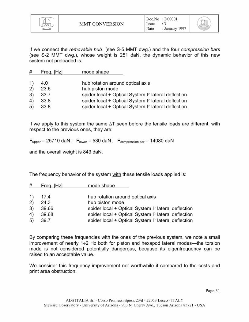
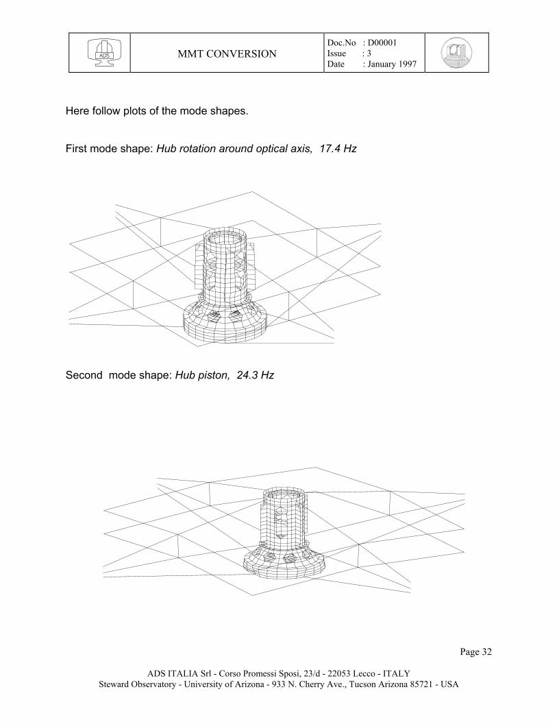
Here follow plots of the mode shapes. First mode shape: Hub rotation around optical axis, 17.4 Hz
Second mode shape: Hub piston, 24.3 Hz