Embed Size (px)
Citation preview

1
MMT Conversion f/9 Secondary Assembly Procedure
MMT Conversion Technical Memo #00-5, 25 May 2000
S. C. West Multiple Mirror Telescope Observatory, Tucson, AZ
R. AllenSteward Observatory Mirror Laboratory, Tucson, AZ
AbstractA detailed pictorial procedure for assembling and aligning the MMT f/9 secondary cell, mirror, and sup-
port system is given.
I. OverviewWe document the assembly procedure used to integrate andadjust the f/9 mirror into its cell (a la automotive service man-ual style). Further details and clarifications can be found in B.Cuerden, “Install4 Rev A, MMT f/9 Secondary Mirror Instal-lation into Cell, 24-Feb-00, MMT Conversion Internal Techni-cal Memo #00-3, 24 May 2000). The photos and annotationsare more clear using the color pdf version of this memo foundon the MMT website (f9assembly.pdf).
II. Cell and Tripod SetupThere are two ways to bring the mirror and cell together. Thefirst uses a vacuum fixture applied to the faceplate of the mir-ror to lift the mirror into the cell. We will not use this proce-dure. However we show a photo in case this fixture is needed
in the future.
Instead we will use fixturing that moves the cell up onto themirror using a special tripod made for the purpose. Note the 3
nuts (arrows) must be installed prior to setting the cell onto thetripod.
Now place cell over tripod.
Next, set up the 3 pads on the tripod legs that will support themirror. The next two photos show the pad dimensions prior to
2
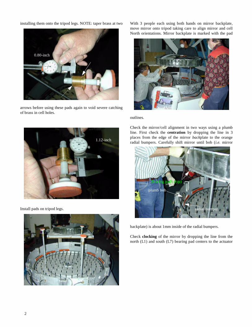
installing them onto the tripod legs. NOTE: taper brass at two
arrows before using these pads again to void severe catchingof brass in cell holes.
Install pads on tripod legs.
With 3 people each using both hands on mirror backplate,move mirror onto tripod taking care to align mirror and cellNorth orientations. Mirror backplate is marked with the pad
outlines.
Check the mirror/cell alignment in two ways using a plumbline. First check the centration by dropping the line in 3places from the edge of the mirror backplate to the orangeradial bumpers. Carefully shift mirror until bob (i.e. mirror
backplate) is about 1mm inside of the radial bumpers.
Check clocking of the mirror by dropping the line from thenorth (L1) and south (L7) bearing pad centers to the actuator
00.8 0.8
0.80-inch
1.12-inch
plumb bob
radial bumper
Bearing pads (typ)
3
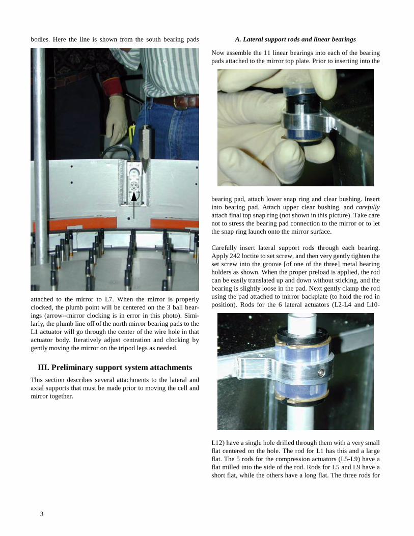
bodies. Here the line is shown from the south bearing pads
attached to the mirror to L7. When the mirror is properlyclocked, the plumb point will be centered on the 3 ball bear-ings (arrow--mirror clocking is in error in this photo). Simi-larly, the plumb line off of the north mirror bearing pads to theL1 actuator will go through the center of the wire hole in thatactuator body. Iteratively adjust centration and clocking bygently moving the mirror on the tripod legs as needed.
III. Preliminary support system attachmentsThis section describes several attachments to the lateral andaxial supports that must be made prior to moving the cell andmirror together.
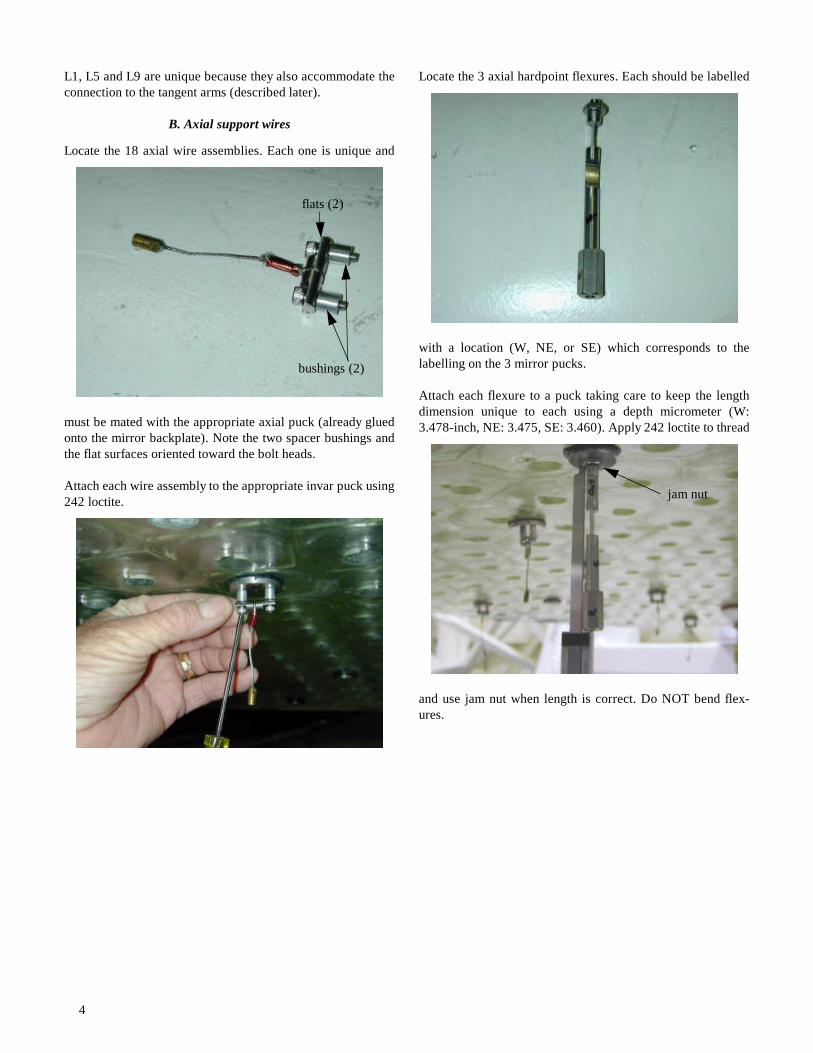
A. Lateral support rods and linear bearings
Now assemble the 11 linear bearings into each of the bearingpads attached to the mirror top plate. Prior to inserting into the
bearing pad, attach lower snap ring and clear bushing. Insertinto bearing pad. Attach upper clear bushing, and carefullyattach final top snap ring (not shown in this picture). Take carenot to stress the bearing pad connection to the mirror or to letthe snap ring launch onto the mirror surface.
Carefully insert lateral support rods through each bearing.Apply 242 loctite to set screw, and then very gently tighten theset screw into the groove [of one of the three] metal bearingholders as shown. When the proper preload is applied, the rodcan be easily translated up and down without sticking, and thebearing is slightly loose in the pad. Next gently clamp the rodusing the pad attached to mirror backplate (to hold the rod inposition). Rods for the 6 lateral actuators (L2-L4 and L10-
L12) have a single hole drilled through them with a very smallflat centered on the hole. The rod for L1 has this and a largeflat. The 5 rods for the compression actuators (L5-L9) have aflat milled into the side of the rod. Rods for L5 and L9 have ashort flat, while the others have a long flat. The three rods for
4
L1, L5 and L9 are unique because they also accommodate theconnection to the tangent arms (described later).
B. Axial support wires
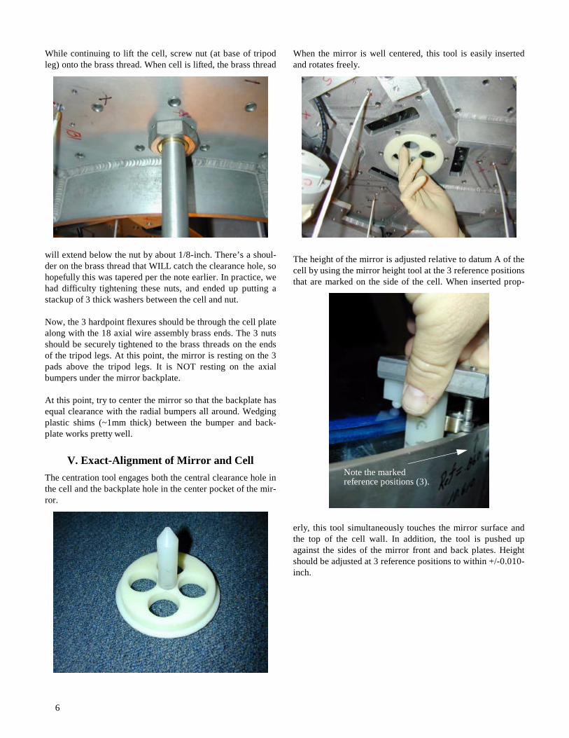
Locate the 18 axial wire assemblies. Each one is unique and
must be mated with the appropriate axial puck (already gluedonto the mirror backplate). Note the two spacer bushings andthe flat surfaces oriented toward the bolt heads.
Attach each wire assembly to the appropriate invar puck using242 loctite.
Locate the 3 axial hardpoint flexures. Each should be labelled
with a location (W, NE, or SE) which corresponds to thelabelling on the 3 mirror pucks.
Attach each flexure to a puck taking care to keep the lengthdimension unique to each using a depth micrometer (W:3.478-inch, NE: 3.475, SE: 3.460). Apply 242 loctite to thread
and use jam nut when length is correct. Do NOT bend flex-ures.
bushings (2)
flats (2)
jam nut

5
Screw wire feed-throughs onto the brass screw on each axialsupport wire assembly. These allow the axial wires to be
steered through the holes in the cellplate.
IV. Mate cell and mirrorNOTE: For this procedure, we used scissor jacks and woodcribbing. It should not be done this way again. A better waywould be to make a support for the mirror cell attached to aprecision fork lift.
Using 3 scissor jacks, elevate cell until wire feeds just touchcell plate. Continue elevating while carefully placing eachwire feed through its appropriate hole in the cell.
Take care to keep mirror centered and clocked properly as thecell is lifted. Also make certain that the tripod legs remaincentered in their clearance holes in the cell plate. Use plumbbob as needed. Also, gently pull on wire feed-throughs tomake sure axial cable doesn’t buckle as cell is lifted.
Continue jacking and cribbing. Occasionally inspect hardpointflexures to insure they proceed through their cell clearance
holes without binding. NOTE: Also check the clearance
between the mirror backplate and the radial bumpers to makesure that the mirror doesn’t hang up there. Pay special atten-tion to the brass threads on the ends of the axial wires so theyproceed through their clearance holes without binding orhanging up.
Watch for contact with the 3 cell clearance holes and the brassthread on the ends of the tripod legs. Be careful not to jack tri-
pod base off the platform because the brass thread binds withthe clearance hole! Make sure to check hardpoint flexureclearance during this process.
wire feed (18)
Datum A
hardpoint flexurewith inspection mirror.
brass thread
tripod leg
wire feed
6
While continuing to lift the cell, screw nut (at base of tripodleg) onto the brass thread. When cell is lifted, the brass thread
will extend below the nut by about 1/8-inch. There’s a shoul-der on the brass thread that WILL catch the clearance hole, sohopefully this was tapered per the note earlier. In practice, wehad difficulty tightening these nuts, and ended up putting astackup of 3 thick washers between the cell and nut.
Now, the 3 hardpoint flexures should be through the cell platealong with the 18 axial wire assembly brass ends. The 3 nutsshould be securely tightened to the brass threads on the endsof the tripod legs. At this point, the mirror is resting on the 3pads above the tripod legs. It is NOT resting on the axialbumpers under the mirror backplate.
At this point, try to center the mirror so that the backplate hasequal clearance with the radial bumpers all around. Wedgingplastic shims (~1mm thick) between the bumper and back-plate works pretty well.
V. Exact-Alignment of Mirror and CellThe centration tool engages both the central clearance hole inthe cell and the backplate hole in the center pocket of the mir-ror.
When the mirror is well centered, this tool is easily insertedand rotates freely.
The height of the mirror is adjusted relative to datum A of thecell by using the mirror height tool at the 3 reference positionsthat are marked on the side of the cell. When inserted prop-
erly, this tool simultaneously touches the mirror surface andthe top of the cell wall. In addition, the tool is pushed upagainst the sides of the mirror front and back plates. Heightshould be adjusted at 3 reference positions to within +/-0.010-inch.
Note the marked reference positions (3).
7
The mirror height is adjusted with the nylon nuts from the 3tripod pads.
Check all the radial bumpers to insure they have a uniformclearance of about 0.040 to 0.05-inch from the edge of themirror backplate. Adjustments are provided by the jam nutassemblies outside the cell OD.
Using small holes in cell sidewalls, insert a cable tie (thick-ness of about 0.03 to 0.04-inch) between the mirror backplateand the axial bumper system under the mirror. The axial
bumpers are directly under the mirror sidewall, so some caremust be taken to push the tie in properly and far enough. Ver-ify clearance for all axial bumpers. If adjustment is necessary,the radial bumper above it must be backed away from the mir-
ror edge to allow access to the axial bumper brackets. This is a
difficult adjustment indeed.
Adjust centration, height and clocking precisely before pro-ceeding. Verify proper radial and axial bumper clearances forthis mirror position.
Finally, remove all the wire feed-throughs.
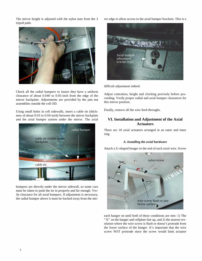
VI. Installation and Adjustment of the Axial Actuators
There are 18 axial actuators arranged in an outer and innerring.
A. Installing the axial hardware
Attach a U-shaped hanger to the end of each axial wire. Screw
each hanger on until both of these conditions are met: 1) The“X” on the hanger and cellplate line up, and 2) the nearest rev-olution where the wire screw is flush or doesn’t protrude fromthe lower surface of the hanger. It’s important that the wirescrew NOT protrude since the screw would limit actuator
cable tie
cable tie visible underbackplate
radial bumper
Axial bumperadjustmentbracket (typ)
X’s
wire screw flush or just below surface.
nylon screw
8
travel rather then the hanger surface. End by slightly tighten-ing the nylon screw.
Next attach the actuator cylinder to the cell by first aligningthe X’s on the actuator with the X’s on the hangar and cell.There are 3 pairs of push-pull screws (the pullers are in the 3larger diameter holes in the actuator face). Use the pullers tojust snug the actuator body up against the cell for now. NOTE:the puller screws for the outer ring of actuators are shorterthan those for the inner ring of actuators.
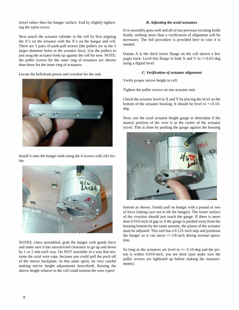
Locate the bellofram piston and crossbar for the unit.
Install it onto the hanger ends using the 4 screws with 242 loc-tite.
NOTES: Once assembled, grab the hanger with gentle forceand make sure it has unrestricted clearance to go up and downby 1 or 2 mm each way. Do NOT assemble in a way that ten-sions the axial wire rope, because you could pull the puck offof the mirror backplate. In this same spirit, be very carefulmaking mirror height adjustments henceforth. Raising themirror height relative to the cell could tension the wire ropes!
B. Adjusting the axial actuators
If re-assembly goes well and all of our previous loctiting holdsfirmly, nothing more than a verification of alignment will benecessary. The full procedure is provided here in case it isneeded.
Datum A is the thick lower flange on the cell shown a fewpages back. Level this flange in both X and Y to +/-0.05-degusing a digital level.
C. Verification of actuator alignment
Verify proper mirror height in cell.
Tighten the puller screws on one actuator unit.
Check the actuator level in X and Y by placing the level on thebottom of the actuator housing. It should be level to +/-0.10-deg.
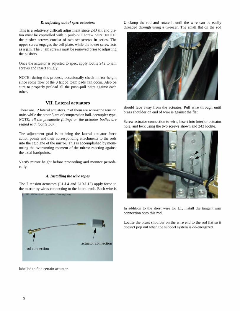
Next, use the axial actuator height gauge to determine if theneutral position of the wire is at the center of the actuatortravel. This is done by pushing the gauge against the housing
bottom as shown. Gently pull on hangar with a pound or twoof force (taking care not to tilt the hangar). The lower surfaceof the crossbar should just touch the gauge. If there is morethan 0.010-inch of gap or if the gauge is pushed away from thehousing bottom by the same amount, the piston of the actuatormust be adjusted. This tool has a 0.125-inch step and positionsthe hanger so it can move +/-1/8-inch during normal opera-tion.
So long as the actuators are level to +/- 0.10-deg and the pis-ton is within 0.010-inch, you are done (just make sure thepuller screws are tightened up before making the measure-ments).
9
D. adjusting out of spec actuators
This is a relatively difficult adjustment since 2-D tilt and pis-ton must be controlled with 3 push-pull screw pairs! NOTE:the pusher screws consist of two set screws in series. Theupper screw engages the cell plate, while the lower screw actsas a jam. The 3 jam screws must be removed prior to adjustingthe pushers.
Once the actuator is adjusted to spec, apply loctite 242 to jamscrews and insert snugly.
NOTE: during this process, occasionally check mirror heightsince some flow of the 3 tripod foam pads can occur. Also besure to properly preload all the push-pull pairs against eachother.
VII. Lateral actuatorsThere are 12 lateral actuators. 7 of them are wire-rope tensionunits while the other 5 are of compression ball-decoupler type.NOTE: all the pneumatic fittings on the actuator bodies aresealed with loctite 567.
The adjustment goal is to bring the lateral actuator forceaction points and their corresponding attachments to the rodsinto the cg plane of the mirror. This is accomplished by moni-toring the overturning moment of the mirror reacting againstthe axial hardpoints.
Verify mirror height before proceeding and monitor periodi-cally.
A. Installing the wire ropes
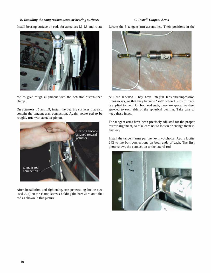
The 7 tension actuators (L1-L4 and L10-L12) apply force tothe mirror by wires connecting to the lateral rods. Each wire is
labelled to fit a certain actuator.
Unclamp the rod and rotate it until the wire can be easilythreaded through using a tweezer. The small flat on the rod
should face away from the actuator. Pull wire through untilbrass shoulder on end of wire is against the flat.
Screw actuator connection to wire, insert into interior actuatorhole, and lock using the two screws shown and 242 loctite.
In addition to the short wire for L1, install the tangent armconnection onto this rod.
Loctite the brass shoulder on the wire end to the rod flat so itdoesn’t pop out when the support system is de-energized.
rod connectionactuator connection
10
B. Installing the compression actuator bearing surfaces
Install bearing surface on rods for actuators L6-L8 and rotate
rod to give rough alignment with the actuator piston--thenclamp.
On actuators L5 and L9, install the bearing surfaces that alsocontain the tangent arm connection. Again, rotate rod to beroughly true with actuator piston.
After installation and tightening, use penetrating loctite (weused 222) on the clamp screws holding the hardware onto therod as shown in this picture.
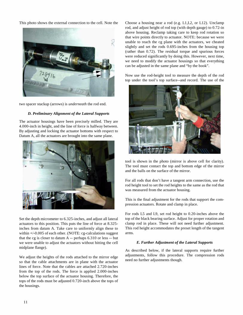
C. Install Tangent Arms
Locate the 3 tangent arm assemblies. Their positions in the
cell are labelled. They have integral tension/compressionbreakaways, so that they become “soft” when 15-lbs of forceis applied to them. On both rod ends, there are spacer washersepoxied to each side of the spherical bearing. Take care tokeep these intact.
The tangent arms have been precisely adjusted for the propermirror alignment, so take care not to loosen or change them inany way.
Install the tangent arms per the next two photos. Apply loctite242 to the bolt connections on both ends of each. The firstphoto shows the connection to the lateral rod.
tangent rodconnection
Bearing surfacealigned towardactuator.
11
This photo shows the external connection to the cell. Note the
two spacer stackup (arrows) is underneath the rod end.
D. Preliminary Alignment of the Lateral Supports
The actuator housings have been precisely milled. They are4.000-inch in height, and the line of force is halfway between.By adjusting and locking the actuator bottoms with respect toDatum A, all the actuators are brought into the same plane.
Set the depth micrometer to 6.325-inches, and adjust all lateralactuators to this position. This puts the line of force at 8.325-inches from datum A. Take care to uniformly align these towithin +/-0.005 of each other. (NOTE: cg-calculations suggestthat the cg is closer to datum A -- perhaps 6.310 or less -- butwe were unable to adjust the actuators without hitting the cellmidplane flange).
We adjust the heights of the rods attached to the mirror edgeso that the cable attachments are in plane with the actuatorlines of force. Note that the cables are attached 2.720-inchesfrom the top of the rods. The force is applied 2.000-inchesbelow the top surface of the actuator housing. Therefore, thetops of the rods must be adjusted 0.720-inch above the tops ofthe housings.
Choose a housing near a rod (e.g. L1,L2, or L12). Unclamprod, and adjust height of rod top (with depth gauge) to 0.72-inabove housing. Reclamp taking care to keep rod rotation sothat wire points directly to actuator. NOTE: because we wereunable to reach the cg plane with the actuators, we cheatedslightly and set the rods 0.695-inches from the housing top(rather than 0.72). The residual torque and spurious forceswere reduced significantly by doing this. However, next time,we need to modify the actuator housings so that everythingcan be adjusted in the same plane and “by the book”.
Now use the rod-height tool to measure the depth of the rodtop under the tool’s top surface--and record. The use of the
tool is shown in the photo (mirror is above cell for clarity).The tool must contact the top and bottom edge of the mirrorand the balls on the surface of the mirror.
For all rods that don’t have a tangent arm connection, use therod height tool to set the rod heights to the same as the rod thatwas measured from the actuator housing.
This is the final adjustment for the rods that support the com-pression actuators. Rotate and clamp in place.
For rods L5 and L9, set rod height to 0.20-inches above thetop of the black bearing surface. Adjust for proper rotation andclamp rod in place. These will not need further adjustment.This rod height accommodates the preset length of the tangentarms.
E. Further Adjustment of the Lateral Supports
As described below, if the lateral supports require furtheradjustments, follow this procedure. The compression rodsneed no further adjustments though.

12
VIII. Final Adjustment of the Lateral Actuators
A. Move mirror and cell to iron maiden
Using a smooth fork lift, move mirror and cell onto the ironmaiden and attach to the dummy hexapod. Be sure that cell N
and S are perpendicular to the trunnion axis.
B. Install and Adjust the Axial Hardpoint Units
Installation of the axial hardpoints was delayed until now tofacilitate moving the cell with a fork lift. If a special fixture ismade for the lift to provide clearance for the hardpoints, theycould be installed just after the axial actuators (just before sec-tion VII).
Verify and adjust mirror height and centration as needed.
Locate the 3 hardpoint flexure nuts under cell plate.
Locate the 3 axial hardpoint assemblies and attachment hard-ware. Each hardpoint is marked W, NE, or SE with corre-
sponding labels on the cell plate. Each hardpoint has integralcompession and tension breakaways that activate at 15-lbs.
Screw each hardpoint onto the corresponding flexure nut. The
electrical cable coming out of the load cell interferes with thecircular flange in the cell -- carefully handle flexure whilescrewing hardpoint on. Also, apply torque only to load cellbody. Slightly tighten load cell against flexure nut.
Attach the two standoff posts to the cell. If the load cell cableinterferes with any hardware, place a washer in series with itsconnection to the flexure nut to clock it in its tightened posi-tion.
Adjust the thread on the rod-end until the lower block justmates with these posts. Tighten the jam nut. You have to pick
flexure nut

13
the nearest half-turn, so they won’t mate perfectly. Do NOT
screw the two halves of the hardpoint breakaway against eachother (large central thread). If the hardpoint was carefullyremoved, adjustment should be unnecessary.
Verify that the bolt going through the rear rod-end is tight oneach unit. In fact, tightness is critical on these units, so checkand adjust them carefully.
C. Electrical and Pneumatic Connections
There is a box for each of the 4 pneumatic zones (3 axial and 1lateral). An additional box is installed too. The hardware isattached to the back of the cell with the following orientation.
• Connect axial load cells to corresponding color axialboxes.
• Connect red, orange, blue, and yellow pneumatic hoses to“OUT” on corresponding boxes.
• Connect N tangent arm load cell to box labelled Monitor.• Connect SE and SW tangent arms to S box labelled Lat-
eral. The connections can be reversed and proper operationstill results (we only care about the sum of these load celloutputs).
• From the small distribution PC board, connect ribboncables to the boxes: orange lateral -> DR3, red axial ->DR1, yellow axial -> DR2, LCM Monitor -> DR4, andblue axial -> DR5.
• An additional monitor cable gets connected to DR6 wherethe load cells may be monitored with digital meters: SEred axial -> pins 1,14; NE yellow axial -> 7,20; W blueaxial -> pins 5,18, and N tangent arm -> 9,22.
• Connect red lead to +15, blue/purple to -15, and black tothe common ground of a dual power supply.
• Set up nitrogen bottle with a regulator adjusted for 35 psi.Distribute to the 4 boxes to the ports labelled IN.
NOTE: the load cell sensitivities as measured from DR6are all 80mv/lb.
This photo shows the whole system attached to the iron
maiden.
D. Preliminary Power Up
IMPORTANT NOTE: The pressurized air MUST be sup-plied to the cell prior to turning on the electronics. Whenpowering off, the air is turned off AFTER the electronics.
Lower mirror onto the axial bumpers by jacking the nylonscrews under the 3 tripod leg pads. Be certain that pads arebacked away from the mirror backplate.
Rotate cell to horizon-pointing with N up (never rotate S up).Set datum A to 90.0-deg with precision level. Turn on air thenturn on electronics. Mirror should come back to operatingposition under servo control.
Verify mirror height and centration.
BlueAxial Yellow
Axial
Red Axial
Monitor
N
W E
S
NE hardpoint yellow
SE hardpoint red
W hardpointblue
SE tangent rod
SW tangent rod
N tangent rod
LateralOrange
14
Measure N tangent load cell. After removing electronic offset,verify residual force on tangent rods is < 0.25-lb. If larger,there is a clocking error that must be corrected.
We measured the load cell offsets. Also, (+) voltage corre-
sponds to compression and (-) to tension.
Power off electronics.
E. Final Lateral Support Measurements/Adjustments
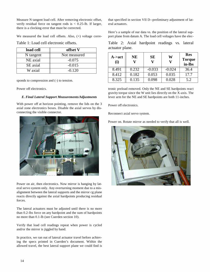
With power off at horizon pointing, remove the lids on the 3axial zone electronics boxes. Disable the axial servos by dis-connecting the visible connector.
Power on air, then electronics. Now mirror is hanging by lat-eral servo system only. Any overturning moment due to a mis-alignment between the lateral supports and the mirror cg planereacts directly against the axial hardpoints producing residualforces.
The lateral actuators must be adjusted until there is no morethan 0.2-lbs force on any hardpoint and the sum of hardpointsno more than 0.1-lb (see Cuerden section 10).
Verify that load cell readings repeat when power is cycledand/or the mirror is jiggled by hand.
In practice, we ran out of lateral actuator travel before achiev-ing the specs printed in Cuerden’s document. Within theallowed travel, the best lateral support plane we could find is
that specified in section VII D--preliminary adjustment of lat-eral actuators.
Here’s a sample of our data vs. the position of the lateral sup-port plane from datum A. The load cell voltages have the elec-
tronic preload removed. Only the NE and SE hardpoints reactgravity torque since the W unit lies directly on the X-axis. Thelever arm for the NE and SE hardpoints are both 11-inches.
Power off electronics.
Reconnect axial servo system.
Power on. Rotate mirror as needed to verify that all is well.
Table 1: Load cell electronic offsets.
load cell offset VN tangent Not measuredNE axial -0.075SE axial -0.015W axial -0.120
disconnect
Table 2: Axial hardpoint readings vs. lateralactuator plane.
A->act (i)
NEV
SEV
WV
Res Torque in-lbs
8.491 0.232 -0.033 -0.024 36.48.412 0.182 0.053 0.035 17.78.325 0.135 0.098 0.028 5.2