Embed Size (px)
Citation preview

MMAANNUUAALL
REBAR CUTTERS & BENDERS DO SO WITH EASE
IMPORTANT!! Please read this carefully to assure peak performance & results
CAUTION: DO NOT attempt to cut or bend any cable with this machine without
special attachments. Contact ROD CHOMPER, INC. for these and any other
questions!
**Fill with Hydraulic oil before starting! (Texaco Rando HD-32 or the equivalent.)
Approximately ________Gallons
Serial #_________________ Machined wired for:
______Volts ______Amps
Model #_________________ ______Phase ______Horsepower
______Cycle
Mfg. Date________________ VIN #___________________________
Rod Chomper, Inc.
4249 58Th Street
Holland, MI 49423 USA
(616) 392-9677 Toll Free US: (866) 392-9677
Website: www.rodchomper.com
Sales- [email protected] Parts & Service- [email protected]

THANK YOU FOR PURCHASING OUR ROD CHOMPER MACHINE! The Rod Chomper has been engineered in a unique way to cut & bend reinforcing rod. It has been computer
designed to last for many years of trouble free service. The Rod Chomper, is made to be used, in shop or on the job
site, depending on the machine. It will cut or bend 1 ¼” re-bar with the proper wheel and pin.
WWAARRNNIINNGG:: 1. When changing the knives, wheel or pins, shut off the machine and lock out power.
2. Keep hands clear from knives, pins and wheels at all times.
3. When bending mode is in operation, never stand in the path of bending bar.
4. DO NOT REMOVE GUARDS!!
5. DO NOT USE over 25 feet of extension cord. Use of a longer cord may result in lower voltage and possible
motor damage.)
6. DO NOT cut or bend anything other than the recommended re-bars in the machines.
GENERAL OPERATING INSTRUCTIONS: 1. CHECK OIL in tank to make sure tank is full before running machine.
2. CHANGE OIL & FILTER in machine once a year.
3. If you have a portable model, also check oil in engine.
4. GREASE machine at all grease fittings as marked. Grease = once a week, Grease Daily = daily. When
greasing Rod Chomper, check to see that the lock nuts are tight on cylinder and pivot bolt.
5. Before plugging in electric machine, check available line voltage. 110, 220 single phase or 220/440 three
phase. A licensed electrician should perform running power to machine for startup. Refer to machine
operators manual or serial # tag to ensure proper machine wiring. It may be necessary, depending on
machine, to add lockable disconnect when wiring.
6. When running machine, KEEP HANDS clear from knives and moving parts at all times.
7. When bending, make sure you are using proper pin and wheel for rod size you are bending. Before bending
rod, back adjustment screw all the way out to set to desired position. After bending a sample piece and the
bend is not correct, adjust screw to obtain your desired degree of bend (see Specific Operating Instructions
for standard hook bending).
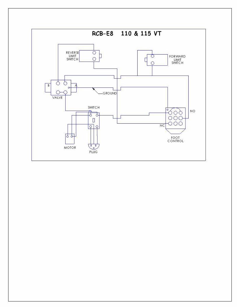
8. When using the Rod Chomper re-bar cutter, first set cut-bend switch on machine control box to cut and insert
bar to be cut to the furthest point possible toward the inside of the blades, making sure that the blades are in
the fully open or retracted position. Press the ON button on control panel of electric machines, start gas
engine on portable machines, REMOVE HANDS, press down foot switch pedal, and bar will be sheared
automatically. When removing pressure on foot pedal, shear jaws are returned to the fully open position.
9. The number of grade #60 bars that the following machines will cut and bend in one operation are as follows:
6 BAR CUT 6 BAR BEND 8 BAR CUT 8 BAR BEND 11 BAR CUT 11 BAR BEND
6-#3 4-#3 8-#3 4-#3 18-#3 4-#3
4-#4 3-#4 6- #4 3- #4 14-#4 4-#4
1-#5 1-#5 2-#5 2-#5 7-#5 2-#5
1-#6 1-#6 1-#6 1-#6 4-#6 2-#6
1-#7 1-#7 2-#7 1-#7
1-#8 1-#8 2-#8 1-#8
1-#9 1-#9
1#-10 1-#10
1-#11 1-#11
10. TO CHANGE OIL- it takes _________ gallons of AW 32 Hydraulic oil or equal. Change filter every 200 hours.
Change oil once a year.


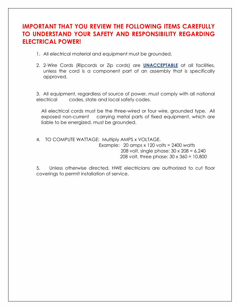
IMPORTANT THAT YOU REVIEW THE FOLLOWING ITEMS CAREFULLY
TO UNDERSTAND YOUR SAFETY AND RESPONSIBILITY REGARDING
ELECTRICAL POWER!
1. All electrical material and equipment must be grounded.
2. 2-Wire Cords (Ripcords or Zip cords) are UNACCEPTABLE at all facilities,
unless the cord is a component part of an assembly that is specifically
approved.
3. All equipment, regardless of source of power, must comply with all national
electrical codes, state and local safety codes.
All electrical cords must be the three-wired or four wire, grounded type. All
exposed non-current carrying metal parts of fixed equipment, which are
liable to be energized, must be grounded.
4. TO COMPUTE WATTAGE: Multiply AMPS x VOLTAGE.
Example: 20 amps x 120 volts = 2400 watts
208 volt, single phase: 30 x 208 = 6,240
208 volt, three phase: 30 x 360 = 10,800
5. Unless otherwise directed, HWE electricians are authorized to cut floor
coverings to permit installation of service.
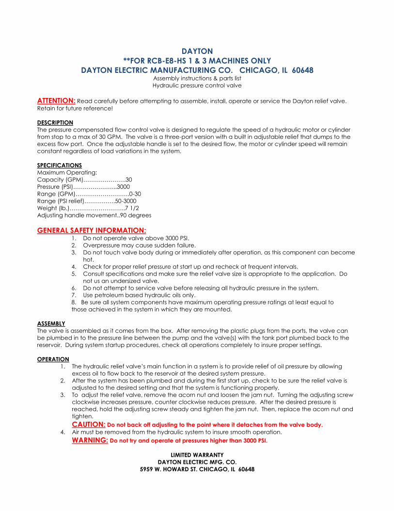
DAYTON
**FOR RCB-E8-HS 1 & 3 MACHINES ONLY
DAYTON ELECTRIC MANUFACTURING CO. CHICAGO, IL 60648 Assembly instructions & parts list
Hydraulic pressure control valve
ATTENTION: Read carefully before attempting to assemble, install, operate or service the Dayton relief valve.
Retain for future reference!
DESCRIPTION
The pressure compensated flow control valve is designed to regulate the speed of a hydraulic motor or cylinder
from stop to a max of 30 GPM. The valve is a three-port version with a built in adjustable relief that dumps to the
excess flow port. Once the adjustable handle is set to the desired flow, the motor or cylinder speed will remain
constant regardless of load variations in the system.
SPECIFICATIONS
Maximum Operating:
Capacity (GPM)………………….30
Pressure (PSI)…………………..3000
Range (GPM)……………………….0-30
Range (PSI relief)…………….50-3000
Weight (lb.)………………………..7 1/2
Adjusting handle movement..90 degrees
GENERAL SAFETY INFORMATION: 1. Do not operate valve above 3000 PSI.
2. Overpressure may cause sudden failure.
3. Do not touch valve body during or immediately after operation, as this component can become
hot.
4. Check for proper relief pressure at start up and recheck at frequent intervals.
5. Consult specifications and make sure the relief valve size is appropriate to the application. Do
not us an undersized valve.
6. Do not attempt to service valve before releasing all hydraulic pressure in the system.
7. Use petroleum based hydraulic oils only.
8. Be sure all system components have maximum operating pressure ratings at least equal to
those achieved in the system in which they are mounted.
ASSEMBLY
The valve is assembled as it comes from the box. After removing the plastic plugs from the ports, the valve can
be plumbed in to the pressure line between the pump and the valve(s) with the tank port plumbed back to the
reservoir. During system startup procedures, check all operations completely to insure proper settings.
OPERATION
1. The hydraulic relief valve’s main function in a system is to provide relief of oil pressure by allowing
excess oil to flow back to the reservoir at the desired system pressure.
2. After the system has been plumbed and during the first start up, check to be sure the relief valve is
adjusted to the desired setting and that the system is functioning properly.
3. To adjust the relief valve, remove the acorn nut and loosen the jam nut. Turning the adjusting screw
clockwise increases pressure, counter clockwise reduces pressure. After the desired pressure is
reached, hold the adjusting screw steady and tighten the jam nut. Then, replace the acorn nut and
tighten.
CAUTION: Do not back off adjusting to the point where it detaches from the valve body.
4. Air must be removed from the hydraulic system to insure smooth operation.
WARNING: Do not try and operate at pressures higher than 3000 PSI.
LIMITED WARRANTY
DAYTON ELECTRIC MFG. CO.
5959 W. HOWARD ST. CHICAGO, IL 60648
HEAVY DUTY FOOT SWITCH
1. READ WARNING STATEMENT on next page.
2. When wiring up this device, make sure POWER IS OFF AND LINES ARE DEAD.
3. When wiring up this device with flexible cord, an UNDERWRITERS LAB LISTED
liquid tight connector, must be provided. Use appropriate pipe thread sealant
at assembly to seal connector threads. When threading into the conduit
opening, care must be taken to tighten the thread joint sufficiently to prevent
loosening but should NOT BE FORCED! The conduit threads should be kept
clean; free from dirt and foreign materials that would hinder proper installation.
4. TO CHANGE ADJUSTMENT of the operating point of an interior switch, depress
the treadle to the point where you want the switch to operate. With the
treadle depressed to the desired operating point, turn the adjusting screw until
the switch snaps. Turn clockwise to lower the operating point and counter
clockwise to raise it. Apply Loctite Corporation Threadlocker Adhesive #290 (or
equivalent) penetrating low-viscosity anaerobic liquid to adjusting screw J after
changing adjustment. Avoid applying and excessive amount of the liquid
adhesive to prevent migration. Remove excess liquid adhesive to prevent
migration. Remove excess liquid adhesive by wiping.
5. Tighten the cover screws so that an effective seal is obtained with the gasket.
6. CLEANLINESS must be observed during installation and in use. On a regular
basis, lubricate the treadle pivot rod with one or two drops of lubricating oil on
that portion of the pivot that extends between the outside of the base and
inside of the treadle; two places. On a regular basis, inspect foot switch
frequently to guard against wear and damage. Unlawful alterations or
removal of guards, or for unusual enclosure deterioration and the like. Inspect
the entire length of the connecting cord (or wiring system) from where it enters
the foot switch to the equipment its wired up to for wear, loose strain relief
connections and the like. DO NOT OPERATE the foot switch if any of the above
is observed or if the nameplate or warning label has been obscured or
removed. It is IMPERATIVE that inspection authorities and users excersice more
than ordinary care with regard to installation and maintenance and that this
info sheet be made available to the end user, operations, maintenance
personnel and to others responsible for the proper installation and safe
operations of this foot switch.
ADDITIONAL COPIES OF THIS INFO AVAILABLE UPON REQUEST

WWAARRNNIINNGG
USE OF FOOT CONTROLS ON MACHINERY, LAKING EFFECTIVE POINT OF
OPERATION SAFE GUARDS, CAN CAUSE SERIOUS INJURY TO THE
OPERATOR! Foot controls should only be used where “Point of Operation” and “Pinch Point” guarding
devices have been properly installed and are utilized so that it is IMPOSSIBLE for the
operator’s hands and fingers to remain within the point of operation during the machine
cycle.
IT IS THE REPONSIBILTY OF THE USER to determine the suitability of a foot control for
the user’s intended use. Also to determine that the foot control chosen by the user, wiring up
and installation, will comply with all Federal State, local safety, health regulations and codes.
Due to the unlimited variety of business equipment, instruments and vehicles on which our
foot switches are used, the thousands of standards, and customers’ varying interpretations of
the standards covering these applications, it is impossible for LINEMASTER personnel to be
experts on standards and requirements for all these products. We offer foot switch models
and guards plus a variety of specials, which are made to customer specifications. We can
advise you what is available in our foot switch line and you can examine models to see what
meets your needs. We believe our customers’ engineering departments should be qualified
experts in their own product field and know what specifications or details they may require in
a foot switch for their equipment. If one of our stock models meets their needs, they can
specify it, or possibly ask for a modification of a stock model if it is required.
SHOULD YOU HAVE ANY QUESTIONS OR IF ANY OF THE ABOVE WARNING IS UNCLEAR, PLEASE
CALL LINEMASTER SWITCH CORPORATION.
(203) 974-1000 /FAX (203) 974-0691
DEFINITIONS: POINT OF OPERATION- The point or area of the machine or equipment where the piece of
material is actually positioned and work is being performed during any process such as
cutting, shearing, forming, welding, riveting, assembling, etc.
PINCH POINT- Any point at which it is possible for a portion of the body to be caught and
injured between a moving machine, equipment, or work piece parts.

ROD CHOMPER INC.
ONE YEAR LIMITED WARRANTY
Rod Chomper, Inc. will warrant each new machine to be
free from defects in material and workmanship for a
period of one year from date of purchase. As long as
the machine is properly installed and subjected to normal
use and service. This warranty is void if the machine is
changed or modified in any way.
If a customer needs warranty service, he should contact
the dealer from whom he purchased the machine. Then
the dealer will contact Rod Chomper, Inc. and receive
a returned goods authorization number if required.
Rod Chomper, Inc. will determine the method of satisfying
the warranty. If Rod Chomper, Inc. determines the
machine should be returned to the factory, it must be
accompanied by proof of purchase and a clear
explanation of the exact problem. The machine must be
returned freight pre-paid. No other warranty, except as
stated above, is implied or expressed.
Motors and valves of electric and hydraulic parts are
warranted by manufacture.