Embed Size (px)
Citation preview
DVK90132 MLX90132 Development Kit User Manual
REVISION 006 - JUNE 19, 2017
390129013201
Features and Benefits
Conforms with ISO/IEC 18092 (NFC)
Conforms with ISO/IEC 14443 A and B,
Conforms with ISO/IEC 15693
Conforms with ISO/IEC 18000-3 mode 1
High speed communication (848kbit/s)
Embedded RF field and TAG detectors
Application Example
NFC enabled car for access and start
Ordering information Part Code Temperature Code Package Code Option Code Packing Form Code MLX90132 R (-40°C to 105°C) LQ (Lead free QFN 5x5 32 leads) AEA-000 RE MLX90132 R (-40°C to 105°C) LQ (Lead free QFN 5x5 32 leads) AEA-000 TU
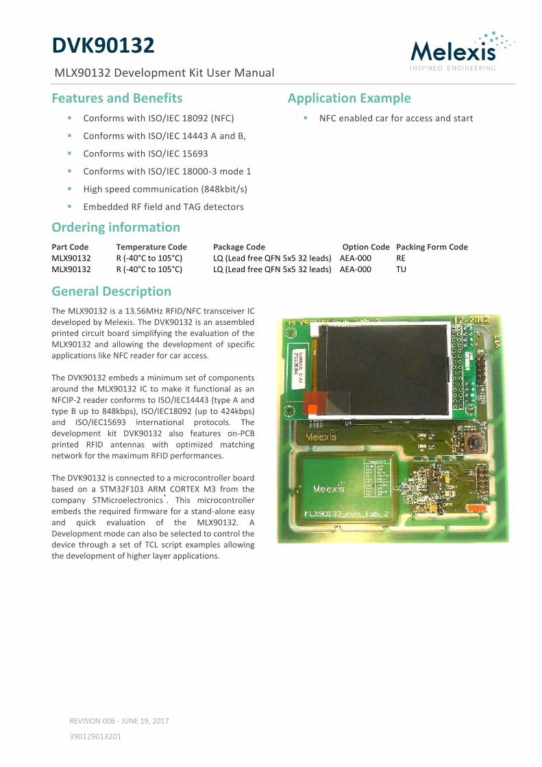
General Description The MLX90132 is a 13.56MHz RFID/NFC transceiver IC developed by Melexis. The DVK90132 is an assembled printed circuit board simplifying the evaluation of the MLX90132 and allowing the development of specific applications like NFC reader for car access. The DVK90132 embeds a minimum set of components around the MLX90132 IC to make it functional as an NFCIP-2 reader conforms to ISO/IEC14443 (type A and type B up to 848kbps), ISO/IEC18092 (up to 424kbps) and ISO/IEC15693 international protocols. The development kit DVK90132 also features on-PCB printed RFID antennas with optimized matching network for the maximum RFID performances. The DVK90132 is connected to a microcontroller board based on a STM32F103 ARM CORTEX M3 from the company STMicroelectronics
®. This microcontroller
embeds the required firmware for a stand-alone easy and quick evaluation of the MLX90132. A Development mode can also be selected to control the device through a set of TCL script examples allowing the development of higher layer applications.
DVK90132 MLX90132 Development Kit User Manual
Page 2 of 20
REVISION 006 - JUNE 19, 2017
390129013201
Contents
Features and Benefits ................................................................................................................................ 1
Application Example .................................................................................................................................. 1
Ordering information ................................................................................................................................ 1
General Description ................................................................................................................................... 1
1. DVK90132 global description ................................................................................................................. 3
2. DVK90132 Schematic & BOM ................................................................................................................ 4
2.1. Schematics .......................................................................................................................................... 4
2.2. Bill of materials ................................................................................................................................... 6
2.3. DVK90132 Printed RFID antennas...................................................................................................... 8
3. Firmware of the DVK90132 ................................................................................................................... 8
4. Installing the Software ........................................................................................................................... 8
4.1. STM32 USB driver ............................................................................................................................... 8
4.2. TCL software........................................................................................................................................ 9
4.2.1. TCL engine: ActiveTcl .................................................................................................................... 9
4.2.2. TCL editor: Ezdit ............................................................................................................................ 9
4.2.3. DVK90132 DLL ............................................................................................................................... 9
5. Getting started with the DVK90132 ..................................................................................................... 10
5.1. Standalone mode .............................................................................................................................. 10
5.2. Development mode .......................................................................................................................... 11
5.2.1. TCL script examples .................................................................................................................... 11
6. Contact ................................................................................................................................................ 20
7. Disclaimer ............................................................................................................................................ 20
DVK90132 MLX90132 Development Kit User Manual
Page 3 of 20
REVISION 006 - JUNE 19, 2017
390129013201
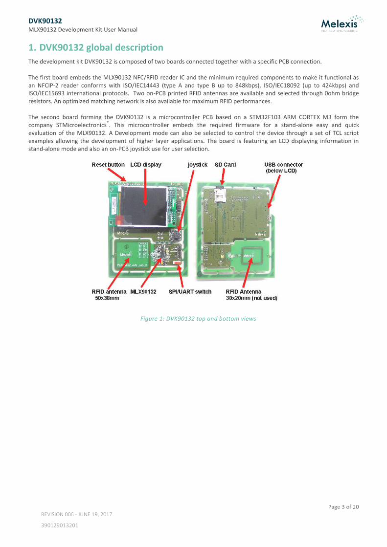
1. DVK90132 global description The development kit DVK90132 is composed of two boards connected together with a specific PCB connection. The first board embeds the MLX90132 NFC/RFID reader IC and the minimum required components to make it functional as an NFCIP-2 reader conforms with ISO/IEC14443 (type A and type B up to 848kbps), ISO/IEC18092 (up to 424kbps) and ISO/IEC15693 international protocols. Two on-PCB printed RFID antennas are available and selected through 0ohm bridge resistors. An optimized matching network is also available for maximum RFID performances. The second board forming the DVK90132 is a microcontroller PCB based on a STM32F103 ARM CORTEX M3 form the company STMicroelectronics
®. This microcontroller embeds the required firmware for a stand-alone easy and quick
evaluation of the MLX90132. A Development mode can also be selected to control the device through a set of TCL script examples allowing the development of higher layer applications. The board is featuring an LCD displaying information in stand-alone mode and also an on-PCB joystick use for user selection.
Figure 1: DVK90132 top and bottom views
DVK90132 MLX90132 Development Kit User Manual
Page 4 of 20
REVISION 006 - JUNE 19, 2017
390129013201
2. DVK90132 Schematic & BOM
2.1. Schematics
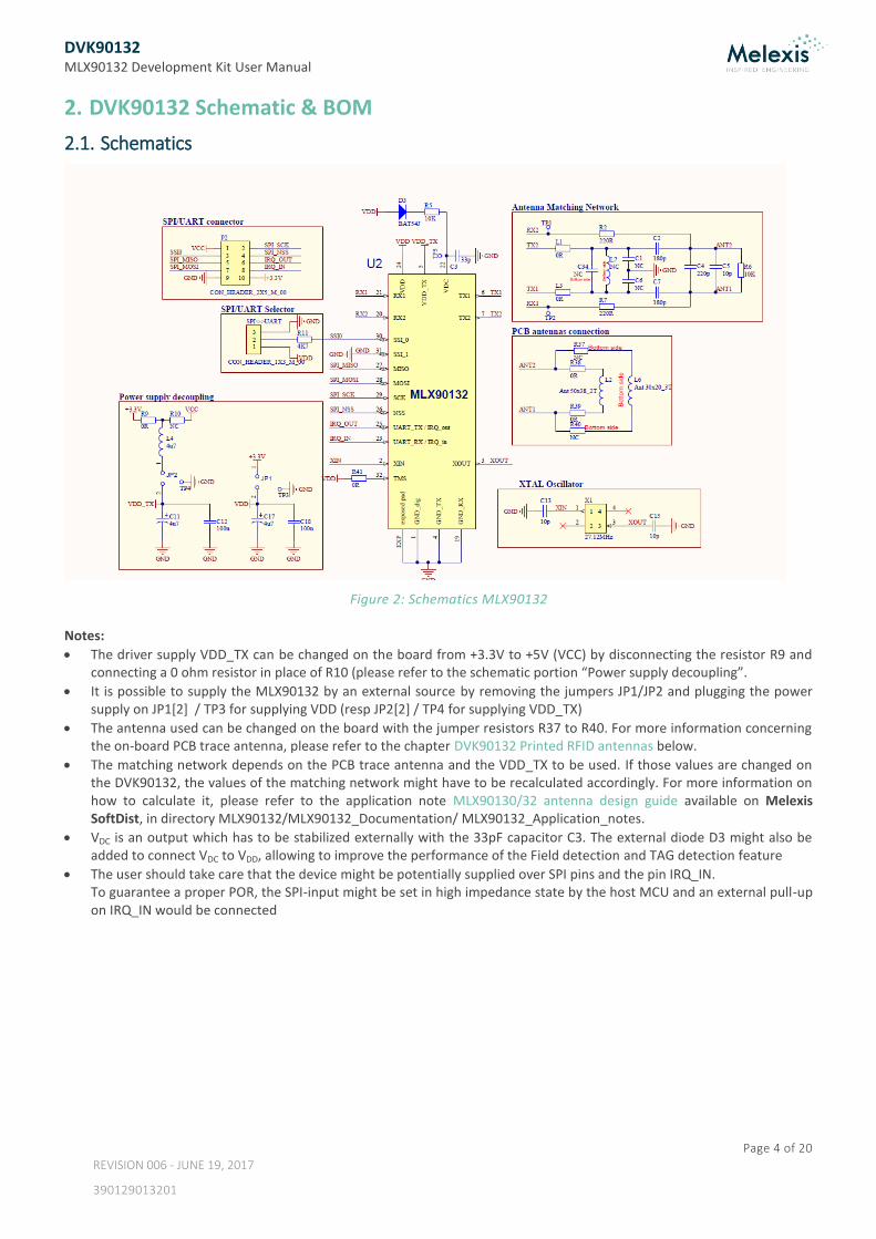
Figure 2: Schematics MLX90132
Notes:
The driver supply VDD_TX can be changed on the board from +3.3V to +5V (VCC) by disconnecting the resistor R9 and connecting a 0 ohm resistor in place of R10 (please refer to the schematic portion “Power supply decoupling”.
It is possible to supply the MLX90132 by an external source by removing the jumpers JP1/JP2 and plugging the power supply on JP1[2] / TP3 for supplying VDD (resp JP2[2] / TP4 for supplying VDD_TX)
The antenna used can be changed on the board with the jumper resistors R37 to R40. For more information concerning the on-board PCB trace antenna, please refer to the chapter DVK90132 Printed RFID antennas below.
The matching network depends on the PCB trace antenna and the VDD_TX to be used. If those values are changed on the DVK90132, the values of the matching network might have to be recalculated accordingly. For more information on how to calculate it, please refer to the application note MLX90130/32 antenna design guide available on Melexis SoftDist, in directory MLX90132/MLX90132_Documentation/ MLX90132_Application_notes.
VDC is an output which has to be stabilized externally with the 33pF capacitor C3. The external diode D3 might also be added to connect VDC to VDD, allowing to improve the performance of the Field detection and TAG detection feature
The user should take care that the device might be potentially supplied over SPI pins and the pin IRQ_IN. To guarantee a proper POR, the SPI-input might be set in high impedance state by the host MCU and an external pull-up on IRQ_IN would be connected
DVK90132 MLX90132 Development Kit User Manual
Page 5 of 20
REVISION 006 - JUNE 19, 2017
390129013201
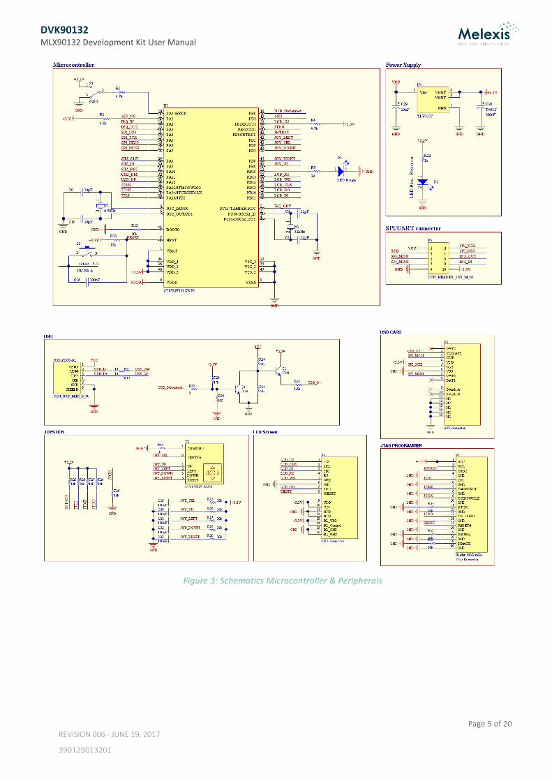
Figure 3: Schematics Microcontroller & Peripherals
DVK90132 MLX90132 Development Kit User Manual
Page 6 of 20
REVISION 006 - JUNE 19, 2017
390129013201
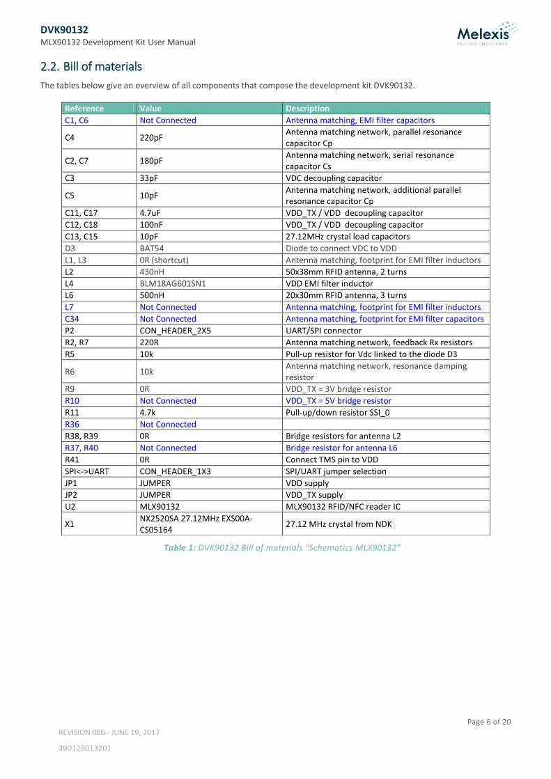
2.2. Bill of materials
The tables below give an overview of all components that compose the development kit DVK90132.
Reference Value Description
C1, C6 Not Connected Antenna matching, EMI filter capacitors
C4 220pF Antenna matching network, parallel resonance capacitor Cp
C2, C7 180pF Antenna matching network, serial resonance capacitor Cs
C3 33pF VDC decoupling capacitor
C5 10pF Antenna matching network, additional parallel resonance capacitor Cp
C11, C17 4.7uF VDD_TX / VDD decoupling capacitor
C12, C18 100nF VDD_TX / VDD decoupling capacitor
C13, C15 10pF 27.12MHz crystal load capacitors
D3 BAT54 Diode to connect VDC to VDD
L1, L3 0R (shortcut) Antenna matching, footprint for EMI filter inductors
L2 430nH 50x38mm RFID antenna, 2 turns
L4 BLM18AG601SN1 VDD EMI filter inductor
L6 500nH 20x30mm RFID antenna, 3 turns
L7 Not Connected Antenna matching, footprint for EMI filter inductors
C34 Not Connected Antenna matching, footprint for EMI filter capacitors
P2 CON_HEADER_2X5 UART/SPI connector
R2, R7 220R Antenna matching network, feedback Rx resistors
R5 10k Pull-up resistor for Vdc linked to the diode D3
R6 10k Antenna matching network, resonance damping resistor
R9 0R VDD_TX = 3V bridge resistor
R10 Not Connected VDD_TX = 5V bridge resistor
R11 4.7k Pull-up/down resistor SSI_0
R36 Not Connected
R38, R39 0R Bridge resistors for antenna L2
R37, R40 Not Connected Bridge resistor for antenna L6
R41 0R Connect TMS pin to VDD
SPI<->UART CON_HEADER_1X3 SPI/UART jumper selection
JP1 JUMPER VDD supply
JP2 JUMPER VDD_TX supply
U2 MLX90132 MLX90132 RFID/NFC reader IC
X1 NX2520SA 27.12MHz EXS00A-CS05164
27.12 MHz crystal from NDK
Table 1: DVK90132 Bill of materials “Schematics MLX90132”
DVK90132 MLX90132 Development Kit User Manual
Page 7 of 20
REVISION 006 - JUNE 19, 2017
390129013201
Reference Value Description
C8, C10 10pF 8MHz crystal load capacitors
C9, C14 22pF 32kHz crystal load capacitors
C16, C19, C20, C21, C22, C23, C24, C25, C26
100nF Decoupling capacitors (Ceramic)
C27, C29, C31, C32, C33 10uF Decoupling capacitors (Tantalum, 20% Tolerance)
C28 10nF Decoupling capacitor (Ceramic)
C30 100uF T491T Decoupling capacitor (Tantalum, 20% Tolerance)
D1, D2 LED green/red LED
L5 BLM18AG601SN1 VDD EMI ferrite
P3 uSD connector uSD connector
P4 LCD Connector LCD Connector
P5 CON_HEADER_2X5 UART/SPI connector
P7 CON_HEADER_2X10 JTAG Connector
Q1, Q2 NPN NPN Bipolar Transistor
R1, R3, R4 4.7k Thick Film Chip Resistor, 1 Ohm to 2.2M Ohm Range, 5% Tolerance, 0402 Size, 0.063 W
R8, R22 1k Rectangular Thick Film Chip Resistor, 10 Ohm to 330k Ohm Range, 0.1% and 0.5% Tolerance, 0603 Size, 0.063 W
R12, R15, R16, R17, R18, R20, R23, R25, R26, R27, R28, R30, R32, R35
10k Thick Film Chip Resistor, 1 Ohm to 2.2M Ohm Range, 5% Tolerance, 0402 Size, 0.063 W
R13, R24 10k Rectangular Thick Film Chip Resistor, 10 Ohm to 330k Ohm Range, 0.1% and 0.5% Tolerance, 0603 Size, 0.063 W
R14, R19, R21 10 Rectangular Thick Film Chip Resistor, 10 Ohm to 330k Ohm Range, 0.1% and 0.5% Tolerance, 0603 Size, 0.063 W
R29 47k Rectangular Thick Film Chip Resistor, 10 Ohm to 330k Ohm Range, 0.1% and 0.5% Tolerance, 0603 Size, 0.063 W
R31 1.5k Rectangular Thick Film Chip Resistor, 10 Ohm to 330k Ohm Range, 0.1% and 0.5% Tolerance, 0603 Size, 0.063 W
R33 0 Rectangular Thick Film Chip Resistor, 10 Ohm to 330k Ohm Range, 0.1% and 0.5% Tolerance, 0603 Size, 0.063 W
R34 33k Rectangular Thick Film Chip Resistor, 10 Ohm to 330k Ohm Range, 0.1% and 0.5% Tolerance, 0603 Size, 0.063 W
S1 SW-3 Switch 2 positions (microcontroller Wake-up)
S2 SW-PB A Push-Button (Reset)
U1 STM32F103CBT6 STM32 ARM-based 32-bit MCU with 128 Kbytes Flash, 48-pin LQFP
U3 JOYSTICK ALPS 4 directions + 1 selection buttons
U4 TLV1117 800 mA, Low Voltage, Low Quiescent Current LDO Regulator, 3-Pin SOT-223
USB-PLUG-A1 CON_USB_MINI_B_90 Connector USB-MINI-B, SMD, Right Angled
Y1 NX5032GA 8MHz S1-2070-5030-10 8MHz Crystal Oscillator from NDK
Y2 32kHz 32kHz Crystal Oscillator
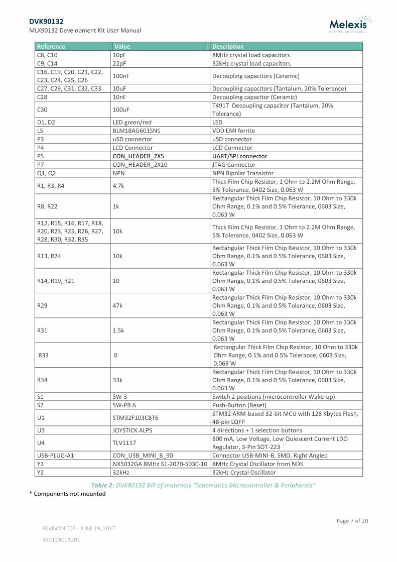
Table 2: DVK90132 Bill of materials “Schematics Microcontroller & Peripherals”
* Components not mounted
DVK90132 MLX90132 Development Kit User Manual
Page 8 of 20
REVISION 006 - JUNE 19, 2017
390129013201
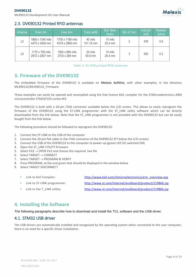
2.3. DVK90132 Printed RFID antennas
Antenna Outer dim. Inner dim. Track width Dist. Btwn
tracks Nbr of Turn
Inductor [nH]
Resistor [ohm]
L2 1880 x 1340 mils 4475 x 3404 mm
1700 x 1169 mils 4318 x 2969 mm
40 mils 101.16 mm
10 mils 25.4 mm
2 430 0.6
L6 1170 x 790 mils 2972 x 2007 mm
1064 x 684 mils 2703 x 269 mm
20 mils 50.8 mm
10 mils 25.4 mm
3 500 0.2
Table 3: On-PCB printed RFID antennas
3. Firmware of the DVK90132 The embedded firmware of the DVK90132 is available on Melexis SoftDist, with other examples, in the directory MLX90132/MLX90132_Firmware. Those examples can easily be opened and recompiled using the free licence KEIL compiler for the STMicroelectronics ARM microcontroller STM32F103 cortex M3. The DVK90132 is built with a 20-pin JTAG connector available below the LCD screen. This allows to easily reprogram the firmware of the DVK90132 using the ST-LINK programmer with the ST_LINK utility software which can be directly downloaded from the link below. Note that the ST_LINK programmer is not provided with the DVK90132 but can be easily bought from the link below. The following procedure should be followed to reprogram the DVK90132: 1. Connect the ST-LINK to the USB of the computer 2. Connect the 20-pin flat cable to the JTAG connector of the DVK90132 (P7 below the LCD screen) 3. Connect the USB of the DVK90132 to the computer to power-up (green LED D2 switched ON) 4. Open the ST_LINK UTILITY firmware 5. Select FILE -> OPEN FILE and choose the required .hex file 6. Select TARGET -> CONNECT 7. Select TARGET -> PROGRAM & VERIFY 8. Press PROGRAM, at the end green text should be displayed in the window below 9. Select TARGET DISCONNECT
Link to Keil Compiler: http://www.keil.com/stmicroelectronics/arm_overview.asp
Link to ST-LINK programmer: http://www.st.com/internet/evalboard/product/219866.jsp
Link to the T_LINK utility: http://www.st.com/internet/evalboard/product/219866.jsp
4. Installing the Software The following paragraphs describe how to download and install the TCL software and the USB driver.
4.1. STM32 USB driver
The USB drivers are automatically installed and recognized by the operating system when connected to the user computer; there is no need for a specific driver installation.
DVK90132 MLX90132 Development Kit User Manual
Page 9 of 20
REVISION 006 - JUNE 19, 2017
390129013201
4.2. TCL software
There are several possibilities to interface the DVK90132 and software available to write TCL scripts. The following paragraphs propose a suite of software which can be downloaded and used for free. The user has to agree with the respective software license.
4.2.1. TCL engine: ActiveTcl
The software can be downloaded on: http://www.activestate.com/activetcl/downloads, but is also available on Melexis
SoftDist, in directory MLX90132/MLX90132_Software. Select the version 8.6.1 for Windows (x86) and install it. This software includes the TCL compiler.
4.2.2. TCL editor: Ezdit
The software (also available on Melexis SoftDist in directory MLX90132/MLX90132_Software) can be downloaded on: http://code.google.com/p/ezdit/downloads/detail?name=ezdit-windows-0.9.1.zip&can=2&q, This editor allows to edit, to create and to execute TCL scripts. It can be used without installation. To link the editor to the TCL engine installed with ActiveTCL (named wish85 or wish86 depending on the version), it is necessary to do the following:
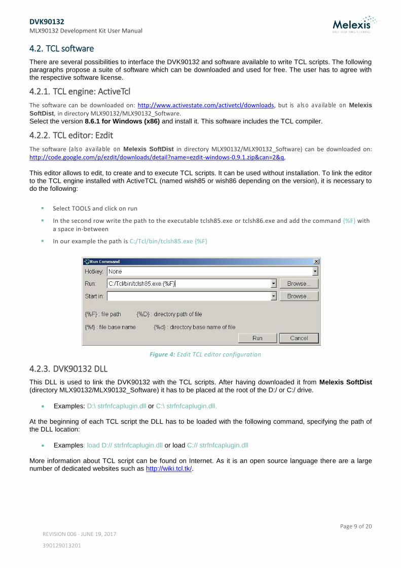
Select TOOLS and click on run
In the second row write the path to the executable tclsh85.exe or tclsh86.exe and add the command {%F} with a space in-between
In our example the path is C:/Tcl/bin/tclsh85.exe {%F}
Figure 4: Ezdit TCL editor configuration
4.2.3. DVK90132 DLL
This DLL is used to link the DVK90132 with the TCL scripts. After having downloaded it from Melexis SoftDist (directory MLX90132/MLX90132_Software) it has to be placed at the root of the D:/ or C:/ drive.
Examples: D:\ strfnfcaplugin.dll or C:\ strfnfcaplugin.dll. At the beginning of each TCL script the DLL has to be loaded with the following command, specifying the path of the DLL location:
Examples: load D:// strfnfcaplugin.dll or load C:// strfnfcaplugin.dll More information about TCL script can be found on Internet. As it is an open source language there are a large number of dedicated websites such as http://wiki.tcl.tk/.
DVK90132 MLX90132 Development Kit User Manual
Page 10 of 20
REVISION 006 - JUNE 19, 2017
390129013201
5. Getting started with the DVK90132 The DVK90132 allows very quick and easy evaluation of the MLX90132 NFC/RFID reader IC. By simply connecting the USB port to the user computer, the DVK90132 is supplied and Start-up menu appears. Then the user simply has to select the mode by moving left/right the Joystick on the board (a blue square shows the mode currently selected) and press on it. The communication interface UART or SPI is selected with the switch “SPI <-> UART” at power-up of the DVK90132. Any change of this jumper after power-up will not have any impact anymore without a complete reset of the board by removing the USB connection. The selected communication interface is displayed at bottom-right side of the LCD screen.
Figure 5: Start-up menu (Standalone/Development mode selection when UART is selected)
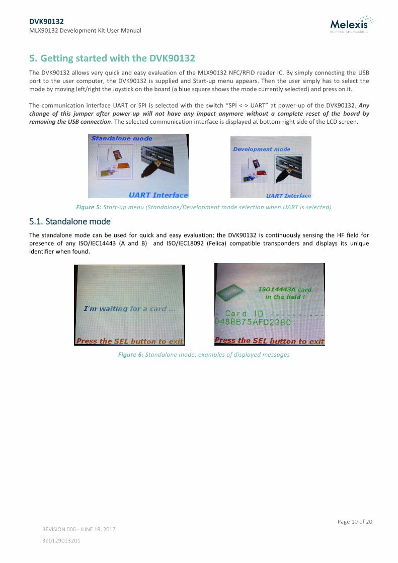
5.1. Standalone mode
The standalone mode can be used for quick and easy evaluation; the DVK90132 is continuously sensing the HF field for presence of any ISO/IEC14443 (A and B) and ISO/IEC18092 (Felica) compatible transponders and displays its unique identifier when found.
Figure 6: Standalone mode, examples of displayed messages
DVK90132 MLX90132 Development Kit User Manual
Page 11 of 20
REVISION 006 - JUNE 19, 2017
390129013201
5.2. Development mode
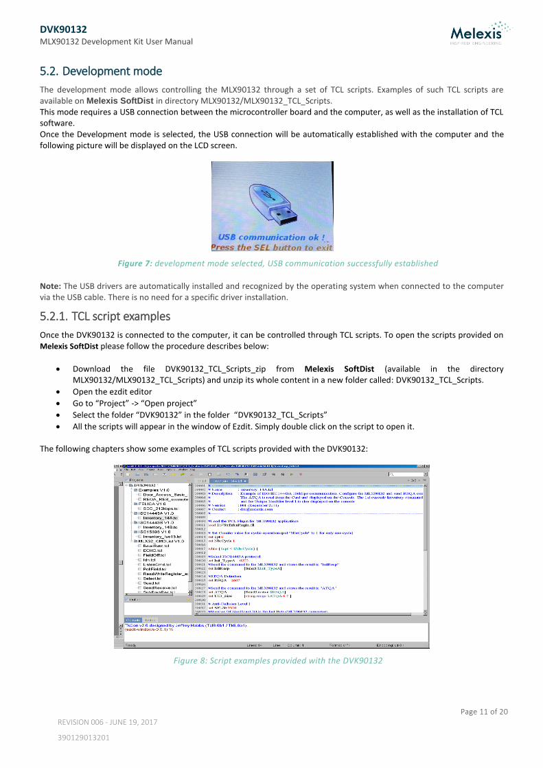
The development mode allows controlling the MLX90132 through a set of TCL scripts. Examples of such TCL scripts are available on Melexis SoftDist in directory MLX90132/MLX90132_TCL_Scripts. This mode requires a USB connection between the microcontroller board and the computer, as well as the installation of TCL software. Once the Development mode is selected, the USB connection will be automatically established with the computer and the following picture will be displayed on the LCD screen.
Figure 7: development mode selected, USB communication successfully established
Note: The USB drivers are automatically installed and recognized by the operating system when connected to the computer via the USB cable. There is no need for a specific driver installation.
5.2.1. TCL script examples
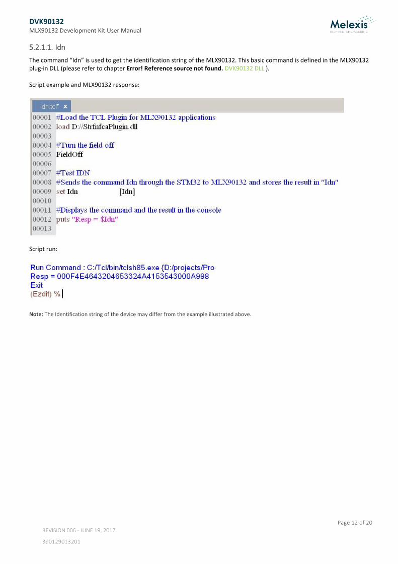
Once the DVK90132 is connected to the computer, it can be controlled through TCL scripts. To open the scripts provided on Melexis SoftDist please follow the procedure describes below:
Download the file DVK90132_TCL_Scripts_zip from Melexis SoftDist (available in the directory MLX90132/MLX90132_TCL_Scripts) and unzip its whole content in a new folder called: DVK90132_TCL_Scripts.
Open the ezdit editor
Go to “Project” -> “Open project”
Select the folder “DVK90132” in the folder “DVK90132_TCL_Scripts”
All the scripts will appear in the window of Ezdit. Simply double click on the script to open it. The following chapters show some examples of TCL scripts provided with the DVK90132:
Figure 8: Script examples provided with the DVK90132
DVK90132 MLX90132 Development Kit User Manual
Page 12 of 20
REVISION 006 - JUNE 19, 2017
390129013201
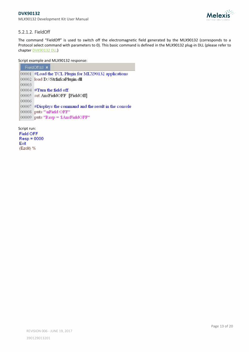
5.2.1.1. Idn
The command “Idn” is used to get the identification string of the MLX90132. This basic command is defined in the MLX90132 plug-in DLL (please refer to chapter Error! Reference source not found. DVK90132 DLL ). Script example and MLX90132 response:
Script run:
Note: The Identification string of the device may differ from the example illustrated above.
DVK90132 MLX90132 Development Kit User Manual
Page 13 of 20
REVISION 006 - JUNE 19, 2017
390129013201
5.2.1.2. FieldOff
The command “FieldOff” is used to switch off the electromagnetic field generated by the MLX90132 (corresponds to a Protocol select command with parameters to 0). This basic command is defined in the MLX90132 plug-in DLL (please refer to chapter DVK90132 DLL) Script example and MLX90132 response:
Script run:
DVK90132 MLX90132 Development Kit User Manual
Page 14 of 20
REVISION 006 - JUNE 19, 2017
390129013201
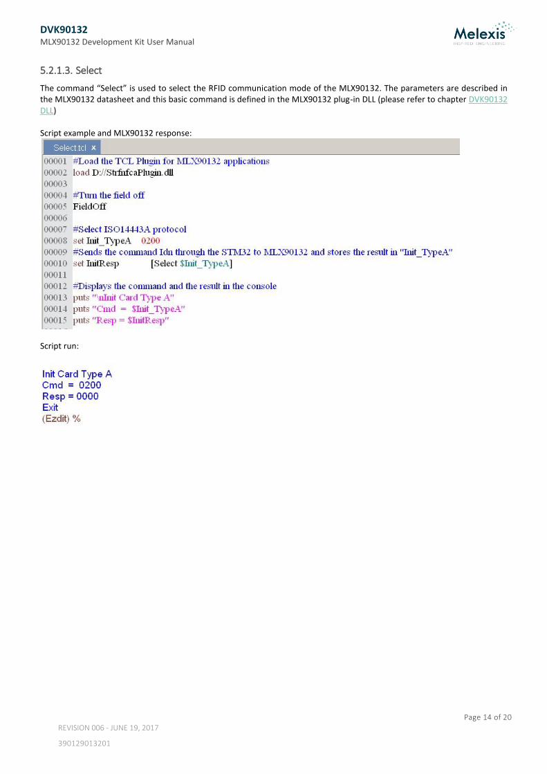
5.2.1.3. Select
The command “Select” is used to select the RFID communication mode of the MLX90132. The parameters are described in the MLX90132 datasheet and this basic command is defined in the MLX90132 plug-in DLL (please refer to chapter DVK90132 DLL) Script example and MLX90132 response:
Script run:
DVK90132 MLX90132 Development Kit User Manual
Page 15 of 20
REVISION 006 - JUNE 19, 2017
390129013201
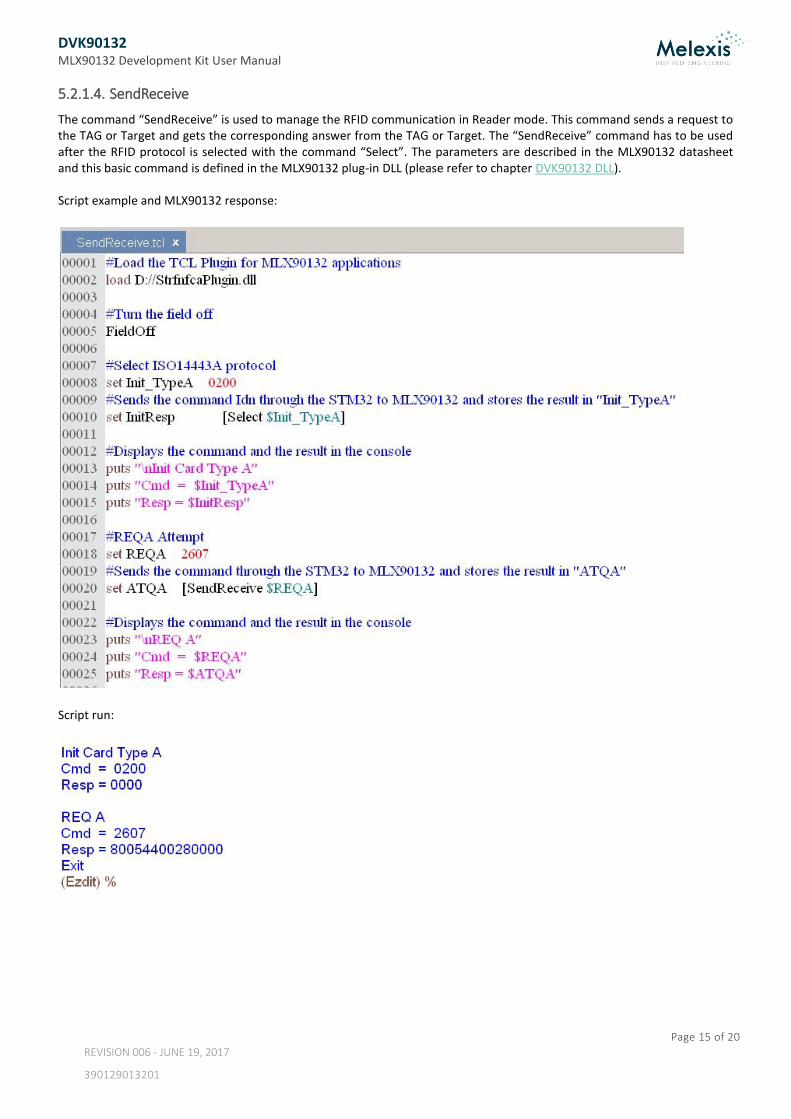
5.2.1.4. SendReceive
The command “SendReceive” is used to manage the RFID communication in Reader mode. This command sends a request to the TAG or Target and gets the corresponding answer from the TAG or Target. The “SendReceive” command has to be used after the RFID protocol is selected with the command “Select”. The parameters are described in the MLX90132 datasheet and this basic command is defined in the MLX90132 plug-in DLL (please refer to chapter DVK90132 DLL). Script example and MLX90132 response:
Script run:
DVK90132 MLX90132 Development Kit User Manual
Page 16 of 20
REVISION 006 - JUNE 19, 2017
390129013201
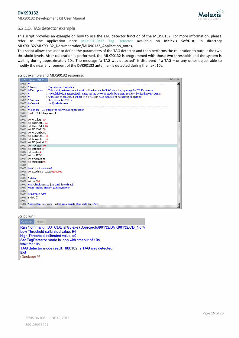
5.2.1.5. TAG detector example
This script provides an example on how to use the TAG detector function of the MLX90132. For more information, please refer to the application note MLX90130/32 Tag Detector available on Melexis SoftDist, in directory MLX90132/MLX90132_Documentation/MLX90132_Application_notes. This script allows the user to define the parameters of the TAG detector and then performs the calibration to output the two threshold levels. After calibration is performed, the MLX90132 is programmed with those two thresholds and the system is waiting during approximately 10s. The message “a TAG was detected” is displayed if a TAG – or any other object able to modify the near environment of the DVK90132 antenna - is detected during the next 10s. Script example and MLX90132 response:
Script run:
DVK90132 MLX90132 Development Kit User Manual
Page 17 of 20
REVISION 006 - JUNE 19, 2017
390129013201
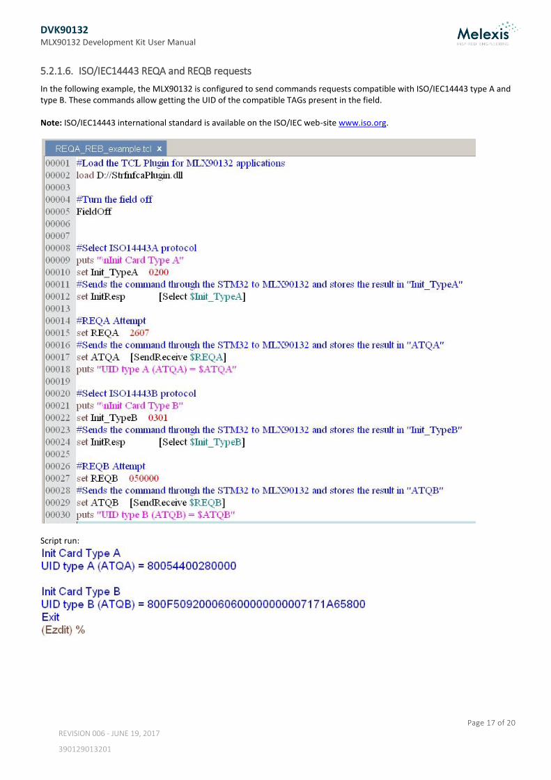
5.2.1.6. ISO/IEC14443 REQA and REQB requests
In the following example, the MLX90132 is configured to send commands requests compatible with ISO/IEC14443 type A and type B. These commands allow getting the UID of the compatible TAGs present in the field. Note: ISO/IEC14443 international standard is available on the ISO/IEC web-site www.iso.org.
Script run:
DVK90132 MLX90132 Development Kit User Manual
Page 18 of 20
REVISION 006 - JUNE 19, 2017
390129013201
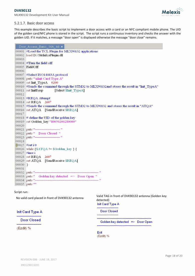
5.2.1.7. Basic door access
This example describes the basic script to implement a door access with a card or an NFC compliant mobile phone. The UID of the golden card/NFC phone is stored in the script. The script runs a continuous inventory and checks the answer with the golden UID. If it matches, a message “door open” is displayed otherwise the message “door close” remains.
Script run:
No valid card placed in front of DVK90132 antenna Valid TAG in front of DVK90132 antenna (Golden key detected)
DVK90132 MLX90132 Development Kit User Manual
Page 19 of 20
REVISION 006 - JUNE 19, 2017
390129013201
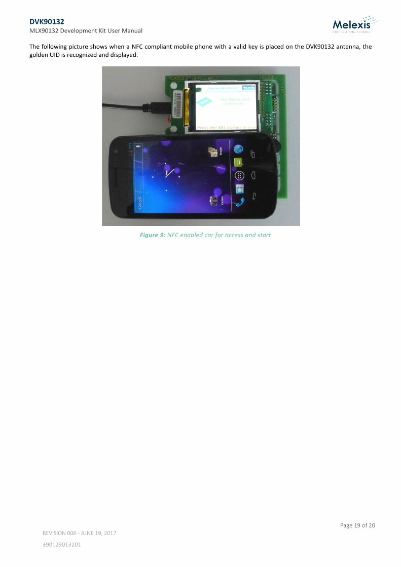
The following picture shows when a NFC compliant mobile phone with a valid key is placed on the DVK90132 antenna, the golden UID is recognized and displayed.
Figure 9: NFC enabled car for access and start

DVK90132 MLX90132 Development Kit User Manual
Page 20 of 20
REVISION 006 - JUNE 19, 2017
390129013201
6. Contact
For the latest version of this document, go to our website at www.melexis.com. For additional information, please contact our Direct Sales team and get help for your specific needs:
Europe, Africa Telephone: +32 13 67 04 95
Email : [email protected]
Americas Telephone: +1 603 223 2362
Email : [email protected]
Asia Email : [email protected]
7. Disclaimer The information furnished by Melexis herein (“Information”) is believed to be correct and accurate. Melexis disclaims (i) any and all liability in connection with or arising out of the furnishing, performance or use of the technical data or use of the product(s) as described herein (“Product”) (ii) any and al l liability, including without limitation, special, consequential or incidental damages, and (iii) any and all warranties, express, statutory, implied, or by description, including warranties of fitness for particular purpose, non-infringement and merchantability. No obligation or liability shall arise or flow out of Melexis’ rendering of technical or other services. The Information is provided "as is” and Melexis reserves the right to change the Information at any time and without notice. Therefore, before placing orders and/or prior to designing the Product into a system, users or any third party should obtain the latest version of the relevant information to verify that the information being relied upon is current. Users or any third party must further determine the suitability of the Product for its application, including the level of reliability required and determine whether it is fit for a particular purpose. The Information is proprietary and/or confidential information of Melexis and the use thereof or anything described by the In formation does not grant, explicitly or implicitly, to any party any patent rights, licenses, or any other intellectual property rights. This document as well as the Product(s) may be subject to export control regulations. Please be aware that export might require a prior authorization from competent authorities. The Product(s) are intended for use in normal commercial applications. Unless otherwise agreed upon in writing, the Product(s ) are not designed, authorized or warranted to be suitable in applications requiring extended temperature range and/or unusual environmental requirements. High reliability applications, such as medical life-support or life-sustaining equipment are specifically not recommended by Melexis. The Product(s) may not be used for the following applications subject to export control regulations: the development, production, processing, operation, maintenance, storage, recognition or proliferation of 1) chemical, biological or nuclear weapons, or for the development, production, maintenance or storage of missiles for such weapons: 2) civil firearms, including spare parts or ammunition for such arms; 3) defense related products, or other material for military use or for law enforcement; 4) any applications that, alone or in combination with other goods, substances or organisms could cause serious harm to persons or goods and that can be used as a means of violence in an armed conflict or any similar violent situation. The Products sold by Melexis are subject to the terms and conditions as specified in the Terms of Sale, which can be found at https://www.melexis.com/en/legal/terms-and-conditions. This document supersedes and replaces all prior information regarding the Product(s) and/or previous versions of this document. Melexis NV © - No part of this document may be reproduced without the prior written consent of Melexis. (2016) ISO/TS 16949 and ISO14001 Certified


![Rev. 1.0 07 April 20144 User manual - NXP Community · 2020. 9. 1. · ISO/IEC 18092 Target [19]: NFC Interface and Protocol standard that enables NFC Data Exchange protocol. Component](https://img.pdfslide.us/doc/110x75/61282fbafad4fb6fce132d81/rev-10-07-april-20144-user-manual-nxp-community-2020-9-1-isoiec-18092.jpg)