Embed Size (px)
Citation preview

MÖLLER-WEDEL OPTICAL GmbH
Rosengarten 10D-22880 Wedel
Tel : +49 - (0) 41 03 - 9 37 76 10Fax: +49 - (0) 41 03 - 9 37 76 60
www.moeller-wedel-optical.come-mail: [email protected]
Printedin
Germ
anyE05/07

Col l imat ors
Tes t ing Te lescopes
Aut oco l l imat ors
A l ignment Sys t ems
MEASUR ING & TESTINGINSTRUMENTS
MEASUR ING & TESTINGINSTRUMENTS
Opt ica lOpt ica l

This catalogue has been developed to offer solutions for common mea-
suring tasks and gives an overview of visual autocollimators, collimators,
testing telescopes, alignment systems, diopter telescopes, dynameters,
modules and accessories.
The following table helps you to select the correct instrument group
for specific measurement tasks.
Convince yourself of our expertise in other fields of optical metrology
and ask for our Overview Catalogue „OPTICAL TEST EQUIPMENT“ and/or
our catalogues „INTERFEROMETER“, „MEASURING COMBINATION FOR LENSES
ANDOPTICAL SYSTEMS“, „ELECTRONIC AUTOCOLLIMATORS“, „GONIOMETER/
SPECTROMETER“.
I N NOVAT I ON AND QUA L I T YI N NOVAT I ON AND QUA L I T YMachineTo
olIndustry
Optics
Collimators
TestingTelescopes
Autoco
llimators
DiopterTelescopes
Dyn
ameters
Alig
nmen
tSystem
s
Typical measurement tasks
Measurement ofAnglesBack Focal LengthFocal LengthOptical PowerParallelism of windows/flatsPyramidal errorRadius of CurvatureSphericity (qualitative)Flatness of windows (qualitative)
Measurement ofOptical PowerDiopter Graduation
Testing of TelescopesDistance SettingExit pupilField of ViewGraduation of ReticleMagnificationResolution
Measurement ofIndex TablesFlatness of Surface PlatesStraightness of guidewaysParallelism of guidewaysSquareness of guideways
Alignment ofGuideways and TablesBore Holes and Bearings
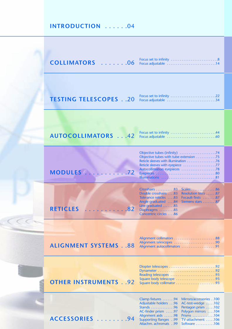
INTRODUCTION . . . . . .04
COLLIMATORS . . . . . . .06
TESTING TELESCOPES . .20
AUTOCOLLIMATORS . . .42
MODULES . . . . . . . . . . .72
RETICLES . . . . . . . . . . .82
ALIGNMENT SYSTEMS . .88
OTHER INSTRUMENTS . .92
ACCESSORIES . . . . . . . .94
Focus set to infinity . . . . . . . . . . . . . . . . . . . . . . . . . .8Focus adjustable . . . . . . . . . . . . . . . . . . . . . . . . . . .14
Focus set to infinity . . . . . . . . . . . . . . . . . . . . . . . . .22Focus adjustable . . . . . . . . . . . . . . . . . . . . . . . . . . .34
Focus set to infinity . . . . . . . . . . . . . . . . . . . . . . . . .44Focus adjustable . . . . . . . . . . . . . . . . . . . . . . . . . . .60
Objective tubes (infinity) . . . . . . . . . . . . . . . . . . . .74Objective tubes with tube extension . . . . . . . . . . .75Reticle sleeves with illumination . . . . . . . . . . . . . . . .76Reticle sleeves with eyepiece . . . . . . . . . . . . . . . . . .77Autocollimation eyepieces . . . . . . . . . . . . . . . . . . .78Eyepieces . . . . . . . . . . . . . . . . . . . . . . . . . . . . . . . . .80Illuminations . . . . . . . . . . . . . . . . . . . . . . . . . . . . . .81
Alignment collimators . . . . . . . . . . . . . . . . . . . . . . .88Alignment telescopes . . . . . . . . . . . . . . . . . . . . . . .90Alignment autocollimators . . . . . . . . . . . . . . . . . . .91
Diopter telescopes . . . . . . . . . . . . . . . . . . . . . . . . . .92Dynameter . . . . . . . . . . . . . . . . . . . . . . . . . . . . . . . .92Reading telescopes . . . . . . . . . . . . . . . . . . . . . . . . .93Square body telescope . . . . . . . . . . . . . . . . . . . . . .93Square body collimator . . . . . . . . . . . . . . . . . . . . . .93
Clamp fixtures . . . . . . .94Adjustable holders . . .96Stands . . . . . . . . . . . . . .96AC-finder prism . . . . .97Alignment aids . . . . . .98Supporting flanges . .99Attachm. achromats . .99
Mirrors/accessories . .100AC-test-wedge . . . . .102Pentagon prism . . . . .102Polygon mirrors . . . .104Prisms . . . . . . . . . . . . .104TV-attachment . . . . .106Software . . . . . . . . . . .106
Crosshairs . . . . . . . . . . .83Double crosshairs . . . .83Tolerance reticles . . . .83Angle graduated . . . .84Line graduated . . . . . . .85Diaphragms . . . . . . . . .85Concentric circles . . . .86
Scales . . . . . . . . . . . . . . .86Resolution tests . . . . . .87Focault-Tests . . . . . . . .87Siemens stars . . . . . . . .87
4 Subject to change without prior notice
AUTOCOLLIM
ATORS
COLLIM
ATORS
INTRODUCTIO
NTESTIN
GTELE
SCOPES
MODULE
SRETICLE
SALIGNMENTSYSTEMS
OTHERIN
STRUMENTS
ACCESSORIES
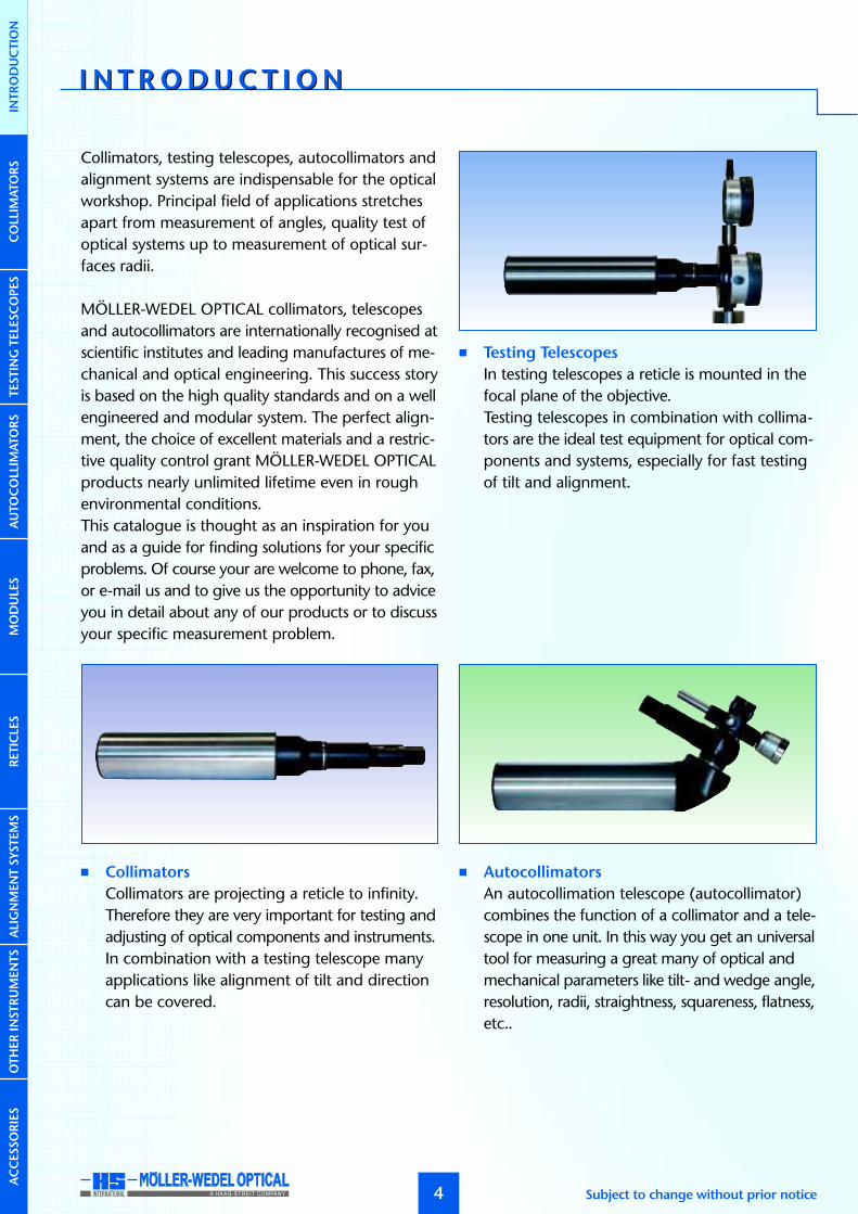
Collimators, testing telescopes, autocollimators andalignment systems are indispensable for the opticalworkshop. Principal field of applications stretchesapart from measurement of angles, quality test ofoptical systems up to measurement of optical sur-faces radii.
MÖLLER-WEDEL OPTICAL collimators, telescopesand autocollimators are internationally recognised atscientific institutes and leading manufactures of me-chanical and optical engineering. This success storyis based on the high quality standards and on a wellengineered and modular system. The perfect align-ment, the choice of excellent materials and a restric-tive quality control grant MÖLLER-WEDEL OPTICALproducts nearly unlimited lifetime even in roughenvironmental conditions.This catalogue is thought as an inspiration for youand as a guide for finding solutions for your specificproblems. Of course your are welcome to phone, fax,or e-mail us and to give us the opportunity to adviceyou in detail about any of our products or to discussyour specific measurement problem.
� Collimators
Collimators are projecting a reticle to infinity.Therefore they are very important for testing andadjusting of optical components and instruments.In combination with a testing telescope manyapplications like alignment of tilt and directioncan be covered.
� Testing Telescopes
In testing telescopes a reticle is mounted in thefocal plane of the objective.Testing telescopes in combination with collima-tors are the ideal test equipment for optical com-ponents and systems, especially for fast testingof tilt and alignment.
� Autocollimators
An autocollimation telescope (autocollimator)combines the function of a collimator and a tele-scope in one unit. In this way you get an universaltool for measuring a great many of optical andmechanical parameters like tilt- and wedge angle,resolution, radii, straightness, squareness, flatness,etc..
I N T R ODUC T I ONI N T R ODUC T I ON

AUTOCOLLIM
ATORS
5www.moeller-wedel-optical.com
COLLIM
ATORS
INTRODUCTIO
NTESTIN
GTELE
SCOPES
MODULE
SRETICLE
SALIGNMENTSYSTEMS
OTHERIN
STRUMENTS
ACCESSORIES
� Modules
Because MÖLLER-WEDEL OPTICAL equipmentis based on a modular concept, components areeasy exchangeable without re-alignment. By thesevarious combinations of modules can be realised,enabling us to deliver good valued customersolutions.
� Reticles
MÖLLER-WEDEL OPTICAL offers reticles coveringthe whole range of applications like adjustmentof reference marks, direct angle measurement,resolution, centration, etc..
� Alignment systems
Alignment telescopes are precision instrumentsfor the alignment of objects on a reference line,which is defined by the line of sight of the system.This property makes them an indispensable toolfor the alignment of bore holes and bearings.Beside alignment telescopes we offer alignmentcollimators and autocollimators. The alignmentautocollimator offers the additional possibilityof measuring the tilt angle of the target withrespect to the reference axis.
� Other Instruments
Beside the standard applications there are instru-ments available for special tasks. Here you will finddiopter-, reading-, square body telescopes, squarebody collimator and dynameter.
� Accessories
In order to get your complete system out of onehand, MÖLLER-WEDEL OPTICAL offers a broadrange of optimal tuned assessories like holders,mirrors, adapter lenses, reticles, targets and TV-equipment.

CO L L I MATOR SCO L L I MATOR SINTRODUCTION
6
Layout and principle of operation
A collimator projects a reticle to a certain distance.Usually the image is at infinity at a wavelength of546 nm.The main components of a collimator are:
� objective tube with objective� reticle sleeve with reticle, condenser and
illumination
The following figure shows the principle set-up of acollimator adjusted to infinity. The reticle is illumina-ted by an illumination system consisting of a conden-ser and light source. The reticle is positioned at thefront focal point of the objective. Due to this configu-ration all light beams passing a point in the reticleplane form a parallel light bundle behind the objec-tive.There is not a real image of the reticle. To get a realimage an additional lens, for example a telescopeobjective, is required.Mechanical and optical axes of collimators withfocal length f≤300 mm are adjusted with an accu-racy of ±30 µm / f.
A measuring unit for tilt angles can be build bycombination of a collimator with a telescope, whenthere is a need to measure in transmission.
Calculation of the angles
The angles (αx and αy) of the parallel beam of a colli-mator adjusted to infinity in respect to its optical axescan be calculated as follows:
f: focal length of the collimator objective∆x: displacement of a point in X-direction∆y: displacement of a point in Y-direction
Numerical example:A point with 3 mm distance from the reticle centerof a collimator with 300 mm focal length is imagedat an angle of:
α ≈ 3/300 rad = 10 ·10-3 rad = 0,5730° = 34’23”
A displacement of 10 µm from the centre of colli-mator reticle is calculated to have the followingangle for the different focal length.
Subject to change without prior notice
AUTOCOLLIM
ATORS
Objective tube Reticle sleeve
αx = arctan(∆x) ≈ ∆xf f
αy = arctan(∆y) ≈ ∆yf f
COLLIM
ATORS
INTRODUCTIO
NTESTIN
GTELE
SCOPES
MODULE
SRETICLE
SALIGNMENTSYSTEMS
OTHERIN
STRUMENTS
ACCESSORIES
50 mm 41”90 mm 23”
140 mm 15”200 mm 10”300 mm 6,9”500 mm 4,1”600 mm 3,4”
1100 mm 1,9”
Focal length Angle

AUTOCOLLIM
ATORS
7
Adjustable Focus
Collimators with adjustable focus are available inaddition to those with fixed focus. Adjustable focuscollimators vary the distance between reticle andobjective.If the reticle is displaced from the focal plane by adistance z, then the collimator is focused at adistance a’ according to:
z < 0 corresponds to a decrease of the distancebetween objective and reticle. The resulting imagedistance is negative (virtual object position) (a).z >0 corresponds to a real image with positive objectdistance (c).z = 0 produces an image at infinite distance (b).
[Bild Fokussierbare Fernrohre]
Selection criteria
Long or short focal length?
A longer focal length leads to small field angles. Asthe focal length increases the field of view decreasesproportionally. For resolution testing choose a colli-mator with equal or slightly larger focal length thanthe optics under test. When used in conjunction witha testing telescope choose the same focal length.Additionally, the intensity of the light bundle emittedfrom the collimator decreases with increased focallength. A longer focal length affects the mechanicalextension of the tube, as well.
Small or large objective aperture?
Light conditions are more favourable when largeapertures are used, and the evaluation of the resultsis easier and more accurate. A long distance betweentest specimen and collimator demands a relativelylarge free aperture (or aperture ratio). For thesemeasurements a relatively large aperture diametershould be used.
Fixed or variable distance setting?
Fixed, infinity focus collimators are generally the bestchoice when testing systems adjusted to infinity.Fixed focus tubes set at other than infinity can beordered.Measuring tasks requiring different wavelengths oflight, or measurements requiring focus other thaninfinity are best accomplished using focusable colli-mators.
www.moeller-wedel-optical.com
(–)a’ (–)z
f (+)z
(+)a’
a)
b)
c)
COLLIM
ATORS
INTRODUCTIO
NTESTIN
GTELE
SCOPES
MODULE
SRETICLE
SALIGNMENTSYSTEMS
OTHERIN
STRUMENTS
ACCESSORIES
a’ = f 2+zfz

CO L L I MATOR SCO L L I MATOR S
COLLIM
ATORS
INTRODUCTIO
NTESTIN
GTELE
SCOPES
AUTOCOLLIM
ATORS
MODULE
SRETICLE
SALIGNMENTSYSTEMS
OTHERIN
STRUMENTS
ACCESSORIES
8
Important:
Please specify illumination (LED-, bulb or cold light,
see page 81) and reticle (see page 82) when ordering.
Subject to change without prior notice
2,5 16,7 45,7 46,5 27,5
Ø3
9
Ø4
0f7
Ø3
9
Ø3
5
Ø3
0
Ø2
4,5
L
225 004 K 50/40 50 10 10,0° 65
225 005 K 90/40 90 16 6,0° 65
225 006 K 140/40 140 28 4,0° 118
225 007 K 200/40 200 28 3,0° 173
225 008 K 300/40 300 28 2,0° 274
225 009 K 500/40 500 28 1,0° 474
Ord.-No. Description Focal length Free aperture Field of view L
Description:
For a general description of the operating principle of collimatorssee page 6.
Application examples:
� Measurement of angular displacements (in conjunction witha telescope)
� Testing of the infinity setting of camera objectives� Testing of the imaging properties of optical elements and
systems
Notes on ordering:
� One reticle, 6V/5W illumination w/cord are included in thedelivery.� If not specified otherwise, the collimator is adjusted to
infinity at 546 nm wavelength. Adjustment to otherdistances or wavelengths is also possible on demand.
� The nomenclature of the collimators is as follows:
Example: K 50/ 40
CollimatorFocal lengthTube diameter
Objective
Condensor
Reticle Illumination

COLLIM
ATORS
INTRODUCTIO
NTESTIN
GTELE
SCOPES
AUTOCOLLIM
ATORS
MODULE
SRETICLE
SALIGNMENTSYSTEMS
OTHERIN
STRUMENTS
ACCESSORIES
9www.moeller-wedel-optical.com
225 015 K 600/128 600 100 0,8° Ø 128 f7 530 46 – 58 154 78
225 016 K 1100/105 1100 78 0,5° Ø 105 f7 1045 66 50 30 165 100
Ord.-No. Description Focal length Free aperture Field of view D a cb d e1 e2
a b
d ce2
136
c e1 d
4
ØD
Ø2
4
Ø3
5
L 194
Ø5
4
Ø3
5
Ø2
4
Ø6
5f7
225 010 K 300/65 300 50 2,0° 233
225 011 K 500/65 500 50 1,0° 415
225 012 K 500T/65 500 50 1,0° 233
Ord.-No. Description Focal length Free aperture Field of view L

COLLIM
ATORS
INTRODUCTIO
NTESTIN
GTELE
SCOPES
AUTOCOLLIM
ATORS
MODULE
SRETICLE
SALIGNMENTSYSTEMS
OTHERIN
STRUMENTS
ACCESSORIES
10 Subject to change without prior notice
CO L L I MATOR SCO L L I MATOR SWITH RETICLE TURRET
5
5
5
5
10
10
10
10
1
23
45
67
8
18
Ø3
9
Ø4
0f7
Ø3
9
Ø3
5
Ø7
0
Ø3
0
Ø2
4,5
2,5 16,7 45,7 46,5 27,5L
225 201 K 50/40 SW 50 10 10,0° 65
225 202 K 90/40 SW 90 16 6,0° 65
225 203 K 140/40 SW 140 28 4,0° 118
225 204 K 200/40 SW 200 28 3,0° 173
225 205 K 300/40 SW 300 28 2,0° 274
225 206 K 500/40 SW 500 28 1,0° 474
Ord.-No. Description Focal length Free aperture Field of view L
Description:
For a general description of the operating principle of collima-tors see page 6.
A collimator with a reticleturret provides 6 selec-table collimator reticles.The reticle turret allowsa quick change of retic-les for different measure-ment tasks.
Application areas:
� Measurement of angular tilt (in conjunction with a telescope)� Testing of the infinity setting of camera objectives� Qualitative testing of the imaging properties of optical
elements and systems
Notes on ordering:
� Six reticles and 6V/5W illumination w/cord are included.� In contrast to collimators with one reticle the optical axis
of the collimator with reticle turret can not be adjusted tobe co-linear with the mechanical axis.
� If not specified otherwise, the collimator is adjusted to in-finity at 546 nm wavelength. Adjustment to other distancesor other wavelengths is also possible on demand.
� The nomenclature of the collimators with reticle turret isas follows:
Example: K 50/ 40 SW
CollimatorFocal lengthTube diameterReticle turret
Important:
Please specify up-to six reticles (see page 82) and illumi-
nation (LED-, bulb- or cold light, see page 81).

COLLIM
ATORS
INTRODUCTIO
NTESTIN
GTELE
SCOPES
AUTOCOLLIM
ATORS
MODULE
SRETICLE
SALIGNMENTSYSTEMS
OTHERIN
STRUMENTS
ACCESSORIES
11www.moeller-wedel-optical.com
225 212 K 600/128 SW 600 100 0,8° Ø 128 f7 530 46 – 58 154 78
225 213 K 1100/105 SW 1100 78 0,5° Ø 105 f7 1045 66 50 30 165 100
Ord.-No. Description Focal length Free aperture Field of view D a cb d e1 e2
a b
d ce2
136
c e1 d
4
ØD
Ø2
4
Ø7
0
L 194
98 18
Ø5
4
Ø2
4
Ø6
5f7
Ø7
0
Ø3
5
225 207 K 300/65 SW 300 50 2,0° 233
225 208 K 500/65 SW 500 50 1,0° 415
225 209 K 500T/65 SW 500 50 1,0° 233
Ord.-No. Description Focal length Free aperture Field of view L

COLLIM
ATORS
INTRODUCTIO
NTESTIN
GTELE
SCOPES
AUTOCOLLIM
ATORS
MODULE
SRETICLE
SALIGNMENTSYSTEMS
OTHERIN
STRUMENTS
ACCESSORIES
CO L L I MATOR SCO L L I MATOR SWITH DOUBLE MICROMETER
12
Description:
For a general description of the operating principle of collima-tors see page 6.
A collimator with double micrometer allows the setting ofdefined image angles in two directions.The movement of the reticle in x- and y-direction in the focalplane is measured with measuring drums. The scale division (SD)is 5 µm.
Application areas:
� Measurement of angular tilt (in conjunction with a telescope)� Qualitative testing of the imaging properties of optical
elements and systems
Notes on ordering:
� One reticle and 6V/5W illumination w/cord are included.� If not specified otherwise, the collimator is adjusted to
infinity at 546 nm wavelength. Adjustment to other dis-tances or other wavelengths is also possible on demand.
� The nomenclature of the collimators with double micro-meter is as follows:
Example: K 50/ 40 MD
CollimatorFocal lengthTube diameterDouble micrometer
∆α
Subject to change without prior notice
Important:
Please specify the reticle (see page 82) and illumination
(LED-, bulb- or cold light, see page 81) when ordering.
2,5 L 16,7 40,9
Ø3
9
Ø4
0f7
Ø3
9
Ø3
5
46,5 27,5
Ø2
5,5
83
78
Ø76
225 281 K 50/40 MD 50 10 3,2° 20,0” 65
225 282 K 90/40 MD 90 16 2,0° 11,5” 65
225 283 K 140/40 MD 140 28 1,2° 7,5” 118
225 284 K 200/40 MD 200 28 0,8° 5,0” 173
225 285 K 300/40 MD 300 28 0,6° 3,5” 274
225 286 K 500/40 MD 500 28 0,4° 2,0” 474
Ord.-No. Description Focal length Free aperture Setting range SD L

COLLIM
ATORS
INTRODUCTIO
NTESTIN
GTELE
SCOPES
AUTOCOLLIM
ATORS
MODULE
SRETICLE
SALIGNMENTSYSTEMS
OTHERIN
STRUMENTS
ACCESSORIES
13www.moeller-wedel-optical.com
225 292 K 600/128 MD 600 100 0,30° 1,7” Ø 128 f7 530 46 – 58 154 78
225 293 K 1100/105 MD 1100 78 0,16° 1,0” Ø 105 f7 1045 66 50 30 165 100
Ord.-No. Description Focal length Free aperture Setting range D a cb d e1 e2
83
78
ØD
Æ76
Ø76
a b
d ce2
136
c e1
4
d
225 287 K 300/65 MD 300 50 0,6° 3,5” 233
225 288 K 500/65 MD 500 50 0,4° 2,0” 415
225 289 K 500T/65 MD 500 50 0,4° 2,0” 233
Ord.-No. Description Focal length Free aperture Setting range SD
SD
L
16,761,5 40,940,9
Ø3
9
Ø3
5
46,5 27,5
Ø2
4,5
83
78
Ø76
L
Ø5
4
Ø6
5f7

COLLIM
ATORS
INTRODUCTIO
NTESTIN
GTELE
SCOPES
AUTOCOLLIM
ATORS
MODULE
SRETICLE
SALIGNMENTSYSTEMS
OTHERIN
STRUMENTS
ACCESSORIES
CO L L I MATOR SCO L L I MATOR SFOCUS ADJUSTABLE
14 Subject to change without prior notice
Description:
For a general description of the operating principle of collima-tors see page 6.
An adjustable focus collimator allows the distance betweenreticle and collimation objective to be adjusted for measure-ments made at other than infinity. Additionally, infinity can beset for different wavelengths of light.
Application areas:
� Testing of distance setting of optical instruments� Adjustment at different wavelengths of light
Notes on ordering:
� One reticle and 6V/5W illumination w/cords are included.� The nomenclature of the adjustable focus collimators is as
follows:
Example: K V 90/ 40/ ±6
CollimatorVariableFocal lengthTube diameterTube extension in mm
(–)z
(+)z
(+)a’
(–)a´
f
46,5 27,5
Ø3
0
Ø2
4,5
16,7 45,7
Ø3
5
Ø3
9
Ø4
0
Ø4
0f7
Ø5
2
L 38
65
12
225 501 KV 90/40/±6 90 16 ±6 6,0° –∞...–1,25 m 77±61,40 m...+∞
225 502 KV 90/40/+12 90 16 +12 6,0° 0,80 m...+∞ 71+12
225 503 KV 90/40/–12 90 16 –12 6,0° –∞...–0,60 m 83–12
225 504 KV 140/40/±6 140 28 ±6 4,0° –∞...–3,10 m 77±63,30 m...+∞
225 505 KV 140/40/+12 140 28 +12 4,0° 1,70 m...+∞ 71+12
225 506 KV 140/40/–12 140 28 –12 4,0° –∞...–1,40 m 83–12
Ord.-No. Description Focallength
Freeaperture
Field ofview
Distancerange
LTubeextension
Important:
Please specify the reticle (see page 82) and illumination
(LED-, bulb- or cold light, see page 81) when ordering.
COLLIM
ATORS
INTRODUCTIO
NTESTIN
GTELE
SCOPES
AUTOCOLLIM
ATORS
MODULE
SRETICLE
SALIGNMENTSYSTEMS
OTHERIN
STRUMENTS
ACCESSORIES
15www.moeller-wedel-optical.com
620 30 215
5
50 100 30
Ø 40
10
2
Ø10
5f7
1045 L4
Ø3
5
Ø6
8
Ø6
5f7
28
,6
1,5
6
10
2
Ø 40
L
A
B
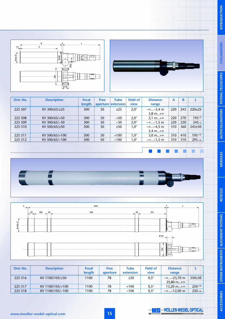
225 516 KV 1100/105/±50 1100 78 ±50 0,5° –∞...–23,70 m 250±5025,80 m...+∞
225 517 KV 1100/105/+100 1100 78 +100 0,5° 13,20 m...+∞ 250+100
225 518 KV 1100/105/–100 1100 78 –100 0,5° –∞...–12,00 m 250–100
Ord.-No. Description Focallength
Freeaperture
Field ofview
Distancerange
LTubeextension
225 507 KV 300/65/±25 300 50 ±25 2,0° –∞...–3,4 m 220 245 220±253,8 m...+∞
225 508 KV 300/65/+50 300 50 +50 2,0° 2,1 m...+∞ 220 270 195+50
225 509 KV 300/65/–50 300 50 –50 2,0° –∞...–1,5 m 220 220 245–50
225 510 KV 500/65/±50 500 50 ±50 1,0° –∞...–4,5 m 310 360 245±505,4 m...+∞
225 511 KV 500/65/+100 500 50 +100 1,0° 3,0 m...+∞ 310 410 195+100
225 512 KV 500/65/–100 500 50 –100 1,0° –∞...–1,5 m 310 310 295–100
Ord.-No. Description Focallength
Freeaperture
Field ofview
Distancerange
LA BTubeextension

COLLIM
ATORS
INTRODUCTIO
NTESTIN
GTELE
SCOPES
AUTOCOLLIM
ATORS
CO L L I MATOR SCO L L I MATOR SFOCUS ADJUSTABLE – WITH RETICLE TURRET
(–)z
(+)a’
(+)zf
(–)a’
MODULE
SRETICLE
SALIGNMENTSYSTEMS
OTHERIN
STRUMENTS
ACCESSORIES
16 Subject to change without prior notice
Important:
Please specify the reticle (see page 82) and illumination
(LED-, bulb- or cold light, see page 81) when ordering.
Ø5
2
Ø4
0
Ø3
9
Ø3
5
Ø7
0
Ø3
0
Ø2
4,5
Ø4
0f7
L 38
65
12 16,7
18
45,7 46,5 27,5
225 701 KV 90/40/±6 SW 90 16 ±6 6,0° –∞...–1,25 m 77±61,40 m...+∞
225 702 KV 90/40/+12 SW 90 16 +12 6,0° 0,80 m...+∞ 71+12
225 703 KV 90/40/–12 SW 90 16 –12 6,0° –∞...–0,60 m 83–12
225 704 KV 140/40/±6 SW 140 28 ±6 4,0° –∞...–3,10 m 77±63,30 m...+∞
225 705 KV 140/40/+12 SW 140 28 +12 4,0° 1,70 m...+∞ 71+12
225 706 KV 140/40/–12 SW 140 28 –12 4,0° –∞...–1,40 m 83–12
Ord.-No. Description Focallength
Freeaperture
Field ofview
Distancerange
LTubeextension
Description:
For a general description of the operating principle of collima-tors see page 6.
An adjustable focus collimator with reticle turret provides 6selectable collimator reticles and allows the distance betweenreticle and collimation objective to be adjusted for measure-ments made at other than infinity. Addi-tionally, infinity can be set for differentwavelengths of light.
Application areas:
� Testing of distance setting of optical instruments� Adjustment at different wavelengths of light
Notes on ordering:
� Six reticles and 6V/5W illumination w/cord are included.� The nomenclature of the adjustable focus collimators with
reticle turret is as follows:
Example: K V 90/ 40/ ±6 SW
CollimatorVariableFocal lengthTube diameterTube extensionReticle turret
5
5
5
5
10
10
10
10
12
3
45
67
8

COLLIM
ATORS
INTRODUCTIO
NTESTIN
GTELE
SCOPES
AUTOCOLLIM
ATORS
MODULE
SRETICLE
SALIGNMENTSYSTEMS
OTHERIN
STRUMENTS
ACCESSORIES
17www.moeller-wedel-optical.com
620 30 215
51045 4 L
50 100 30
Ø 40
10
2
Ø10
5f7
Ø6
8
Ø6
8
28
,6
1,5
10
2
Ø 40
L
A
B
Ø7
0
6
225 716 KV 1100/105/±50 SW 1100 78 ±50 0,5° –∞...–23,70 m 250±5025,80 m...+∞
225 717 KV 1100/105/+100 SW 1100 78 +100 0,5° 13,20 m...+∞ 250+100
225 718 KV 1100/105/–100 SW 1100 78 –100 0,5° –∞...–12,00 m 250–100
Ord.-No. Description Focallength
Freeaperture
Field ofview
Distancerange
LTubeextension
225 707 KV 300/65/±25 SW 300 50 ±25 2,0° –∞...–3,4 m 220 245 220±253,8 m...+∞
225 708 KV 300/65/+50 SW 300 50 +50 2,0° 2,1 m...+∞ 220 270 195+50
225 709 KV 300/65/–50 SW 300 50 –50 2,0° –∞...–1,5 m 220 220 245–50
225 710 KV 500/65/±50 SW 500 50 ±50 1,0° –∞...–4,5 m 310 360 245±505,4 m...+∞
225 711 KV 500/65/+100 SW 500 50 +100 1,0° 3,0 m...+∞ 310 410 195+100
225 712 KV 500/65/–100 SW 500 50 –100 1,0° –∞...–1,5 m 310 310 295–100
Ord.-No. Description Focallength
Freeaperture
Field ofview
Distancerange
LA BTubeextension

COLLIM
ATORS
INTRODUCTIO
NTESTIN
GTELE
SCOPES
AUTOCOLLIM
ATORS
MODULE
SRETICLE
SALIGNMENTSYSTEMS
OTHERIN
STRUMENTS
ACCESSORIES
CO L L I MATOR SCO L L I MATOR SFOCUS ADJUSTABLE – WITH DOUBLE MICROMETER
18
Important:
Please specify the reticle (see page 82) and illumination
(LED-, bulb- or cold light, see page 81) when ordering.
Description:
For a general description of the operating principle of collima-tors see page 6.
An adjustable focus collimator with double micrometer allowsthe setting of defined field angles in two directions and thedistance between reticle and collimation objective to be adjustedfor measurements made at other than infinity.Additionally, infinity can be set for different wavelengths oflight. The scale division (SD) of the micrometer drums is 5 µm.
Application areas:
� Testing of distance setting of optical instruments� Adjustment at different wavelengths of light
Notes on ordering:
� Reticle and 6V/5W illumination w/cord are included.� The nomenclature of the adjustable focus collimators with
double micrometer is as follows:
Example: K V 90/ 40/ ±6 MD
CollimatorVariableFocal lengthTube diameterTube extensionDouble micrometer
(+)a’
(–)z(–)a’
α
(+)zf
∆
∆
∆
Subject to change without prior notice
16,7
Ø3
9
Ø3
5
46,5 27,5
Ø2
4,5
83
78
Ø76
Ø4
0
Ø4
0f7
Ø5
265
L 38 12 40,9
225 801 KV 90/40/±6 MD 90 16 ±6 2,0° 11,5” –∞...–1,25 m 77±61,40 m...+∞
225 802 KV 90/40/+12 MD 90 16 +12 2,0° 11,5” 0,80 m...+∞ 71+12
225 803 KV 90/40/–12 MD 90 16 –12 2,0° 11,5” –∞...–0,60 m 83–12
225 804 KV 140/40/±6 MD 140 28 ±6 1,2° 7,5” –∞...–3,10 m 77±63,30 m...+∞
225 805 KV 140/40/+12 MD 140 28 +12 1,2° 7,5” 1,70 m...+∞ 71+12
225 806 KV 140/40/–12 MD 140 28 –12 1,2° 7,5” –∞...–1,40 m 83–12
Ord.-No. Description Focallength
Freeaperture
Settingrange
Distancerange
LTubeextension
SD

COLLIM
ATORS
INTRODUCTIO
NTESTIN
GTELE
SCOPES
AUTOCOLLIM
ATORS
MODULE
SRETICLE
SALIGNMENTSYSTEMS
OTHERIN
STRUMENTS
ACCESSORIES
19
620 30 215
510454 L
50 100 30
Ø 40
10
2
Ø10
5f7
Ø3
9
Ø3
5
Ø2
4,5
L
www.moeller-wedel-optical.com
83
78
Ø76
Ø3
9
Ø3
5
Ø2
4,5
Ø6
5f7
28
,6
Ø6
8
1,5
6 LB
102
A
225 816 KV 1100/105/±50 MD 1100 78 ±50 0,16° 1,0” –∞...–23,70 m 250±5025,80 m...+∞
225 817 KV 1100/105/+100 MD 1100 78 +100 0,16° 1,0” 13,20 m...+∞ 250+100
225 818 KV 1100/105/–100 MD 1100 78 –100 0,16° 1,0” –∞...–12,00 m 250–100
Ord.-No. Description Focallength
Freeaperture
Settingrange
Distancerange
LTubeextension
225 807 KV 300/65/±25 MD 300 50 ±25 0,6° 3,5” –∞...–3,4 m 220 245 220±253,8 m...+∞
225 808 KV 300/65/+50 MD 300 50 +50 0,6° 3,5” 2,1 m...+∞ 220 270 195+50
225 809 KV 300/65/–50 MD 300 50 –50 0,6° 3,5” –∞...–1,5 m 220 220 245–50
225 810 KV 500/65/±50 MD 500 50 ±50 0,4° 2,0” –∞...–4,5 m 310 360 245±505,4 m...+∞
225 811 KV 500/65/+100 MD 500 50 +100 0,4° 2,0” 3,0 m...+∞ 310 410 195+100
225 812 KV 500/65/–100 MD 500 50 –100 0,4° 2,0” –∞...–1,5 m 310 310 295–100
Ord.-No. Description Focallength
Freeaperture
Settingrange
Distancerange
LA BTubeextension
SD
SD

T E S T I NG T E L E S COP E ST E S T I NG T E L E S COP E SINTRODUCTION
20
Layout and principle of operation
A testing telescope provides a magnified real imageof a distant object. Usually the object is at infinity ata wavelength of 546 nm. The main components ofa testing telescope are:
� objective tube with objective� reticle sleeve with reticle� eyepiece
The following figure shows the principle set-up ofa testing telescope with straight viewing adjustedto infinity. The reticle is positioned at the rear focalplane of the objective. Due to this configuration allobjects at infinity are imaged into the reticle plane.The reticle plane is viewed through the eyepiece.Due to this set-up the image in the eyepiece is ro-tated by 180°.Mechanical and optical axes of testing telescopeswith focal length f≤300 mm are adjusted with anaccuracy of ±30 µm / f.
Testing telescopes form with collimators a measuringsystem for direction and angle testing of optical ele-ments or optical systems in transmission.
Calculation of the angles
The angles (αx and αy ) can be calculated from thedistances ∆x or ∆y of the image of the collimatorreticle to zero position of the eyepiece reticle asfollows:
f: focal length of the telescope objective
Numerical example:A displacement of 3 mm measured with a testingtelescope with 300 mm focal length correspondsto an angle of:
α ≈ 3/300 rad = 10 ·10-3 rad = 0,5730° = 34’23”
A point at a distance of 10 µm to the centre of theeyepiece reticle corresponds to an angle of the paral-lel beam to the optical axis of the telescope as follows:
Subject to change without prior notice
AUTOCOLLIM
ATORS
Objective tube Reticlesleeve
Eyepiece
COLLIM
ATORS
INTRODUCTIO
NTESTIN
GTELE
SCOPES
MODULE
SRETICLE
SALIGNMENTSYSTEMS
OTHERIN
STRUMENTS
ACCESSORIES
αx = arctan(∆x) ≈ ∆xf f
αy = arctan(∆y) ≈ ∆yf f
50 mm 41”90 mm 23”
140 mm 15”200 mm 10”300 mm 6,9”500 mm 4,1”600 mm 3,4”
1100 mm 1,9”
Focal length Angle

AUTOCOLLIM
ATORS
21
Adjustable Focus
Besides testing telescopes with fixed distance bet-ween reticle and objective telescopes with adjustablefocus are available. With these telescopes the distancebetween reticle and objective is adjustable.If the reticle is displaced out of the focal plane bya distance z’, then the telescope is focused at adistance a according to:
z’<0 corresponds to a decrease of the distance bet-ween objective and reticle. The resulting image dis-tance is negative (virtual object position) (a).z’ > 0 corresponds to a real image with positive ob-ject distance (c). z’=0 produces an image at infinitedistance (b).
[Bild Fokussierbare Fernrohre]
Selection criteria
Long or short focal length?
Depending on the magnification of the instrumenta longer focal length leads to a greater measuringsensitivity and measurement accuracy. As the focallength increases, the measuring range (FOV) decrea-ses proportionally. Additionally, the intensity of thelight bundle received by the telescope decreases withincreased focal length. A longer focal length affectsthe mechanical extension of the tube, as well.
Small or large objective aperture?
Light conditions are more favourable when largeapertures are used, and the evaluation of theresults is easier and more accurate. A long distancebetween test specimen and telescope demands arelatively large free aperture (or aperture ratio). Forthese measurements a relatively large aperture dia-meter should be used.
Fixed or variable distance setting?
Fixed, infinity focus testing telescopes are generallythe best choice when testing systems adjusted toinfinity. Fixed focus tubes set at other than infinitycan be ordered.For measurement tasks requiring an adjustable focaldistance like adjustment at different wavelengths orto different distances, focusable testing telescopeswith objective tube with tube extensions are used.
Eyepiece focal length?
Usually eyepieces with f=14,7 mm are used. Eyepie-ces with f=10 mm give greater magnification butless field angle. Eyepieces with f=25 mm give largerfield of view but less magnification. For eyepieceswith f=14,7 mm and f=25 mm a C-Mount Cameraadapter is available.
www.moeller-wedel-optical.com
(+)a
(–)a
f (+)z´
(–)z´
a)
b)
c)
COLLIM
ATORS
INTRODUCTIO
NTESTIN
GTELE
SCOPES
MODULE
SRETICLE
SALIGNMENTSYSTEMS
OTHERIN
STRUMENTS
ACCESSORIES
a = f 2+z’fz’

T E S T I NG T E L E S COP E ST E S T I NG T E L E S COP E SSTRAIGHT VIEWING
22
Description:
For a general description of the operating principle of testingtelescopes see page 20.
Application examples
(additional collimator required):
� Measurement of angular displacement� Parallelism measurement of uncoated flats� Testing of the imaging properties of optical elements and
systems
Notes on ordering:
� Testing telescope eyepiece is commonly f=14,7 mm butcan be equipped with eyepieces f=25 mm or f=10 mm onrequest.
� One reticle and one eyepiece are included in the standardinstrument.
� If not specified otherwise, the testing telescope is adjustedto infinity at 546 nm wavelength. Adjustment to otherdistances or wavelengths is also possible on demand.
� The nomenclature of the testing telescopes with straightviewing is as follows:
Example: F G 50/ 40/ 14,7
Testing telescopeStraight viewingFocal lengthTube diameterEyepiece focal length
Objective tube Reticle Eyepiece
Important:
Please specify reticle (see page 82) when ordering.
Subject to change without prior notice
2,5 L 16,7 45,7 26,7
Ø3
9
Ø4
0f7
Ø3
9
Ø3
5
Ø3
3,8
227 004 FG 50/40/14,7 50 10 10,0° 65
227 005 FG 90/40/14,7 90 16 6,0° 65
227 006 FG 140/40/14,7 140 28 4,0° 118
227 007 FG 200/40/14,7 200 28 3,0° 173
227 008 FG 300/40/14,7 300 28 2,0° 274
227 009 FG 500/40/14,7 500 28 1,0° 474
Ord.-No. Description Focal length Free aperture Field of view L
AUTOCOLLIM
ATORS
COLLIM
ATORS
INTRODUCTIO
NTESTIN
GTELE
SCOPES
MODULE
SRETICLE
SALIGNMENTSYSTEMS
OTHERIN
STRUMENTS
ACCESSORIES

23www.moeller-wedel-optical.com
227 015 FG 600/128/14,7 600 100 0,8° Ø 128 f7 530 46 – 58 154 78
227 016 FG 1100/105/14,7 1100 80 0,5° Ø 105 f7 1045 66 50 30 165 100
Ord.-No. Description Focal length Free aperture Field of view D a cb d e1 e2
a b 88
c e1 d d e2 c 26,7
4
ØD
Ø3
5
Ø3
3,8
L 146
Ø5
4
Ø3
5
Ø3
3,8
Ø6
5f7
26,7
227 010 FG 300/65/14,7 300 50 2,0° 233
227 011 FG 500/65/14,7 500 50 1,0° 415
227 012 FG 500T/65/14,7 500 50 1,0° 233
Ord.-No. Description Focal length Free aperture Field of view L
AUTOCOLLIM
ATORS
COLLIM
ATORS
INTRODUCTIO
NTESTIN
GTELE
SCOPES
MODULE
SRETICLE
SALIGNMENTSYSTEMS
OTHERIN
STRUMENTS
ACCESSORIES

T E S T I NG T E L E S COP E ST E S T I NG T E L E S COP E S90°-VIEWING
24
Description:
For a general description of the operating principle of testingtelescopes see page 20.
The basic function and design of testing telescopes with 90°viewing is the same as of testing telescopes with straight vie-wing.
The testing telescopes with 90° viewing contain an additionalfolding mirror. This kind of testing telescope is used for verticalset-ups or for set-ups on optical tables where straight viewingis not practical from point of view of ergonomics and space.
Application examples
(additional collimator required):
� Measurement of angular displacement� Parallelism measurement of uncoated flats� Testing of the imaging properties of optical elements and
systems� Measurement of the focal length of negative optical systems/
elements (additional attachment achromat required)
Notes on ordering:
� Testing telescope eyepiece is commonly f=14,7 mm butcan be equipped with eyepieces f=25 mm or f=10 mm onrequest.
� One reticle and one eyepiece are included in the standardinstrument.
� If not specified otherwise, the testing telescope is adjusted toinfinity at 546 nm wavelength. Adjustment to other dis-tances or wavelengths is also possible on demand.
� The nomenclature of the testing telescopes with 90°-viewingis as follows:
Example: F R 50/ 40/ 14,7
Testing telescope90° viewingFocal lengthTube diameterEyepiece focal length
Objective tube
Reticle
Foldingmirror
Eyepiece
Important:
Please specify reticle (see page 82) when ordering.
Please specify direction of use if reticles with lettering
(e.g. co-ordinate division etc.) are used so that the
lettering will be right-side-up.
Subject to change without prior notice
69
Ø 34
L
2,5 A
Ø3
9
Ø4
0f7
227 041 FR 50/40/14,7 50 10 10,0° 65 116,5
227 042 FR 90/40/14,7 90 16 6,0° 65 116,5
227 043 FR 140/40/14,7 140 28 4,0° 118 169,5
227 044 FR 200/40/14,7 200 28 3,0° 173 224,5
227 045 FR 300/40/14,7 300 28 2,0° 274 325,5
227 046 FR 500/40/14,7 500 28 1,0° 474 525,5
Ord.-No. Description Focal length Free aperture Field of view A L
AUTOCOLLIM
ATORS
COLLIM
ATORS
INTRODUCTIO
NTESTIN
GTELE
SCOPES
MODULE
SRETICLE
SALIGNMENTSYSTEMS
OTHERIN
STRUMENTS
ACCESSORIES

25www.moeller-wedel-optical.com
227 052 FR 600/128/14,7 600 100 0,8° Ø 128 f7 530 46 – 58 154 78
227 053 FR 1100/105/14,7 1100 78 0,5° Ø 105 f7 1045 66 50 30 165 100
Ord.-No. Description Focal length Free aperture Field of view D a cb d e1 e2
a b
d ce2
44
c e1 d
4
ØD
69
Ø 34
A
L
Ø5
4
Ø6
5f7
Ø 34
69
227 047 FR 300/65/14,7 300 50 2,0° 233 346,0
227 048 FR 500/65/14,7 500 50 1,0° 415 528,0
227 049 FR 500T/65/14,7 500 50 1,0° 233 346,0
Ord.-No. Description Focal length Free aperture Field of view A L
AUTOCOLLIM
ATORS
COLLIM
ATORS
INTRODUCTIO
NTESTIN
GTELE
SCOPES
MODULE
SRETICLE
SALIGNMENTSYSTEMS
OTHERIN
STRUMENTS
ACCESSORIES

T E S T I NG T E L E S COP E ST E S T I NG T E L E S COP E S60°-VIEWING/60°-VIEWING WITH DOUBLE MICROMETER
26 Subject to change without prior notice
Description:
For a general description of the operating principle of testingtelescopes see page 20.
The basic function and design of testing telescopes with 60°-viewing is the same as of testing telescopes with 90°- viewing.The testing telescopes with 60° viewing contain a folding mirror(see following figure). The image appears upright but laterallyreversed. This kind of testing telescopes is used for horizontallyset-ups because the 60°- viewing is more ergonomic.The testing telescopes with 60° viewing (figure A) are availablealso with mechanical micrometer (figure B) and digital doublemicrometers (figure C).The scale division (SD) of the mechanical micrometer drum is5 µm. For a general description of the operating principle oftesting telescopes with double micrometers see page 28 and30 respectively.
Notes on ordering:
� Testing telescope eyepiece is commonly f=14,7 mm butcan be equipped with eyepieces f=25 mm or f=10 mm onrequest.
� One reticle and one eyepiece are included in the standardinstrument.
� If not specified otherwise, the testing telescope is adjusted toinfinity at 546 nm wavelength. Adjustment to other distancesor wavelengths is also possible on demand.
� When ordering a telescope with digital double micrometerplease specify the unit of display of the digital gauges (mm,arcsec, milliradians).
� The nomenclature of the testing telescopes with 60°-viewingand 60° viewing with double micrometer respectively is asfollows:
Example: F W 300/ 65/ 14,7 MDMDD
Testing telescope60° viewingFocal lengthTube diameterEyepiece focal lengthDouble micrometerDigital double micrometer
Folding mirrorObjective
EyepieceBild B
Folding mirrorObjective
Eyepiece
12,3
45
Bild C
Folding mirrorObjective
Eyepiece
Reticle sleeve
Bild A
Important:
Please specify reticle (see page 82) when ordering.
AUTOCOLLIM
ATORS
COLLIM
ATORS
INTRODUCTIO
NTESTIN
GTELE
SCOPES
MODULE
SRETICLE
SALIGNMENTSYSTEMS
OTHERIN
STRUMENTS
ACCESSORIES
Fig. A
Fig. B
Fig. C

27www.moeller-wedel-optical.com
16,7
45,7
26,7
Ø39
Ø35
Ø33,8
L
Ø6
5f7
Ø6
7
45
60 o
83
78
32
Ø34
1746
Ø39
Ø35
L
Ø6
5f7
Ø6
7
45
60 o
Ø34
Ø40
138
35
571746
32
Ø39
Ø35
L
Ø6
5f7
Ø6
7
45
60 o
227 217 FW 300/65/14,7 MDD 300 50 0,6° 1,0“ 233
227 218 FW 500/65/14,7 MDD 500 50 0,4° 0,5” 415
227 219 FW 500T/65/14,7 MDD 500 50 0,4° 0,5” 233
Ord.-No. Description Focal length Free aperture Meas. range Resolution L
60 °-VI EWING WITH DOUBLE MICROMETER
60 °-VI EWING
227 067 FW 300/65/14,7 300 50 2,0° 233
227 068 FW 500/65/14,7 500 50 1,0° 415
227 069 FW 500T/65/14,7 500 50 1,0° 233
Ord.-No. Description Focal length Free aperture Field of view L
AUTOCOLLIM
ATORS
COLLIM
ATORS
INTRODUCTIO
NTESTIN
GTELE
SCOPES
MODULE
SRETICLE
SALIGNMENTSYSTEMS
OTHERIN
STRUMENTS
ACCESSORIES
227 177 FW 300/65/14,7 MD 300 50 0,6° 3,5” 233
227 178 FW 500/65/14,7 MD 500 50 0,4° 2,0” 415
227 179 FW 500T/65/14,7 MD 500 50 0,4° 2,0” 233
Ord.-No. Description Focal length Free aperture Meas. range SD L

T E S T I NG T E L E S COP E ST E S T I NG T E L E S COP E SSTRAIGHT VIEWING – WITH DOUBLE MICROMETER
28
Description:
For a general description of the operating principle of testingtelescopes see page 20.
Testing telescopes with mechanical double micrometer allowthe measurement of deflection angles in two directions. Themovement of the eyepiece reticle in x- and y-direction in theimage plane can be read from the scale of the micrometerdrums. The scale division (SD) is 5 µm.
Application examples
(additional collimator required):
� Measurement of deflection angles� Parallelism measurement of uncoated flats
Notes on ordering:
� Testing telescope eyepiece is commonly f=14,7 mm butcan be equipped with eyepieces f=25 mm or f=10 mm onrequest.
� One reticle and one eyepiece are included in the standardinstrument.
� If not specified otherwise, the testing telescope is adjustedto infinity at 546 nm wavelength. Adjustment to otherdistances or wavelengths is also possible on demand.
� The nomenclature of the testing telescopes with straightviewing and mechanical double micrometer is as follows:
Example: F G 50/ 40/ 14,7 MD
Testing telescopeStraight viewingFocal lengthTube diameterEyepiece focal lengthDouble micrometer
α ∆
Subject to change without prior notice
Important:
Please specify reticle (see page 82) when ordering.
83
78
2,5 L 16,7 40,9 31,5
Ø3
9
Ø4
0f7
Ø3
9
Ø3
5
Ø3
3,8
AUTOCOLLIM
ATORS
COLLIM
ATORS
INTRODUCTIO
NTESTIN
GTELE
SCOPES
MODULE
SRETICLE
SALIGNMENTSYSTEMS
OTHERIN
STRUMENTS
ACCESSORIES
227 161 FG 50/40/14,7MD 50 10 3,2° 20,0” 65
227 162 FG 90/40/14,7MD 90 16 2,0° 11,5” 65
227 163 FG 140/40/14,7MD 140 28 1,2° 7,5” 118
227 164 FG 200/40/14,7MD 200 28 0,8° 5,0” 173
227 165 FG 300/40/14,7MD 300 28 0,6° 3,5” 274
227 166 FG 500/40/14,7MD 500 28 0,4° 2,0” 474
Ord.-No. Description Focal length Free aperture Meas. range SD L

29www.moeller-wedel-optical.com
a b
d ce2
88
e1 d
4
ØD
83
78
c
83
78
L 146
Ø5
4
Ø3
5
Ø3
3,8
Ø6
5f7
227 172 FG 600/128/14,7 MD 600 100 0,30° 1,7” Ø 128 f7 530 46 – 58 154 78
227 173 FG 1100/105/14,7 MD 1100 78 0,16° 1,0” Ø 105 f7 1045 66 50 30 165 100
Ord.-No. Description Focal length Free aperture Meas. range D a cb d e1 e2
AUTOCOLLIM
ATORS
COLLIM
ATORS
INTRODUCTIO
NTESTIN
GTELE
SCOPES
MODULE
SRETICLE
SALIGNMENTSYSTEMS
OTHERIN
STRUMENTS
ACCESSORIES
SD
227 167 FG 300/65/14,7 MD 300 50 0,6° 3,5” 233
227 168 FG 500/65/14,7 MD 500 50 0,4° 2,0” 415
227 169 FG 500T/65/14,7 MD 500 50 0,4° 2,0” 233
Ord.-No. Description Focal length Free aperture Meas. range SD L

T E S T I NG T E L E S COP E ST E S T I NG T E L E S COP E S90°-VIEWING – WITH DOUBLE MICROMETER
30
Description:
For a general description of the operating principle of testingtelescopes see page 20.
Testing telescopes with mechanical double micrometer allowthe measurement of deflection angles in two directions. Themovement of the eyepiece reticle in x- and y-direction in theimage plane can be read from the scale of the micrometerdrums. The scale division (SD) is 5 µm. The following figureshows the set-up of a testing telescope with 90° viewing. Incontrast to a testing telescope with straight viewing the imageappears upright and laterally reversed.
Application examples
(additional collimator required):
� Measurement of deflection angles� Parallelism measurement of uncoated flats
Notes on ordering:
� Testing telescope eyepiece is commonly f=14,7 mm butcan be equipped with eyepieces f=25 mm or f=10 mm onrequest.
� One reticle and one eyepiece are included in the standardinstrument.
� If not specified otherwise, the testing telescope is adjustedto infinity at 546 nm wavelength. Adjustment to other dis-tances or wavelengths is also possible on demand.
� The nomenclature of the testing telescopes with 90°-viewingand mechanical double micrometer is as follows:
Example: F R 50/ 40/ 14,7 MD
Testing telescope90° viewingFocal lengthTube diameterEyepiece focal lengthDouble micrometer
α
Important:
Please specify reticle (see page 82) when ordering.
Please specify direction of use if reticles with lettering
(e.g. co-ordinate division etc.) are used so that the let-
tering will be right-side-up.
Subject to change without prior notice
AUTOCOLLIM
ATORS
COLLIM
ATORS
INTRODUCTIO
NTESTIN
GTELE
SCOPES
MODULE
SRETICLE
SALIGNMENTSYSTEMS
OTHERIN
STRUMENTS
ACCESSORIES

31www.moeller-wedel-optical.com
83 78
Ø 34
A
L
Ø5
4
Ø6
5f7
69
83 78
69
Ø 34
L
2,5 A
Ø3
9
Ø4
0f7
227 187 FR 300/65/14,7MD 300 50 0,6° 3,5” 233 346,0
227 188 FR 500/65/14,7MD 500 50 0,4° 2,0” 415 528,0
227 189 FR 500T/65/14,7MD 500 50 0,4° 2,0” 233 346,0
Ord.-No. Description Focal length Free aperture Meas. range A L
AUTOCOLLIM
ATORS
COLLIM
ATORS
INTRODUCTIO
NTESTIN
GTELE
SCOPES
MODULE
SRETICLE
SALIGNMENTSYSTEMS
OTHERIN
STRUMENTS
ACCESSORIES
SD
227 181 FR 50/40/14,7MD 50 10 3,2° 20,0” 65 116,5
227 182 FR 90/40/14,7MD 90 18 2,0° 11,5” 65 116,5
227 183 FR 140/40/14,7MD 140 28 1,2° 7,5” 118 169,5
227 184 FR 200/40/14,7MD 200 28 0,8° 5,0” 173 224,5
227 185 FR 300/40/14,7MD 300 28 0,6° 3,5” 274 325,5
227 186 FR 500/40/14,7MD 500 28 0,4° 2,0” 474 525,5
Ord.-No. Description Focal length Free aperture Meas. range A LSD
STRAIGHT VIEWING – WITH DIG ITAL DOUBLE MICROMETER
32
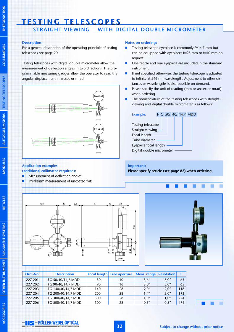
Description:
For a general description of the operating principle of testingtelescopes see page 20.
Testing telescopes with digital double micrometer allow themeasurement of deflection angles in two directions. The pro-grammable measuring gauges allow the operator to read theangular displacement in arcsec or mrad.
Application examples
(additional collimator required):
� Measurement of deflection angles� Parallelism measurement of uncoated flats
Notes on ordering:
� Testing telescope eyepiece is commonly f=14,7 mm butcan be equipped with eyepieces f=25 mm or f=10 mm onrequest.
� One reticle and one eyepiece are included in the standardinstrument.
� If not specified otherwise, the testing telescope is adjustedto infinity at 546 nm wavelength. Adjustment to other dis-tances or wavelengths is also possible on demand.
� Please specify the unit of reading (mm or arcsec or mrad)when ordering.
� The nomenclature of the testing telescopes with straight-viewing and digital double micrometer is as follows:
Example: F G 50/ 40/ 14,7 MDD
Testing telescopeStraight viewingFocal lengthTube diameterEyepiece focal lengthDigital double micrometer
α
0000,0
1234,5
Subject to change without prior notice
227 201 FG 50/40/14,7 MDD 50 10 5,6° 5,0” 65
227 202 FG 90/40/14,7 MDD 90 16 3,0° 5,0” 65
227 203 FG 140/40/14,7 MDD 140 28 2,0° 2,0” 118
227 204 FG 200/40/14,7 MDD 200 28 1,4° 2,0” 173
227 205 FG 300/40/14,7 MDD 300 28 1,0° 1,0” 274
227 206 FG 500/40/14,7 MDD 500 28 0,5° 0,5” 474
Ord.-No. Description Focal length Free aperture Meas. range Resolution L
2,5 17
Ø3
9
Ø4
0f7
Ø76
Ø 40
Ø3
9
Ø3
5
Ø3
4
L 72
35
13
85
7
57138
Important:
Please specify reticle (see page 82) when ordering.
AUTOCOLLIM
ATORS
COLLIM
ATORS
INTRODUCTIO
NTESTIN
GTELE
SCOPES
MODULE
SRETICLE
SALIGNMENTSYSTEMS
OTHERIN
STRUMENTS
ACCESSORIES
T E S T I NG T E L E S COP E ST E S T I NG T E L E S COP E S
33
a b
d ce2
88
c e1 d
4
ØD
Ø3
5
13
85
7
Ø 40
Ø76
138 57
Ø3
4
35
Ø3
4
Ø5
4
Ø3
5
Ø6
5f7
Ø 40
L57138
13
8
146
35
57
Ø76
www.moeller-wedel-optical.com
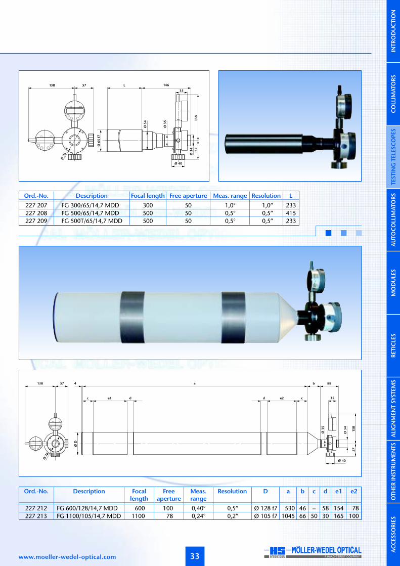
227 207 FG 300/65/14,7 MDD 300 50 1,0° 1,0” 233
227 208 FG 500/65/14,7 MDD 500 50 0,5° 0,5” 415
227 209 FG 500T/65/14,7 MDD 500 50 0,5° 0,5” 233
Ord.-No. Description Focal length Free aperture Meas. range Resolution L
227 212 FG 600/128/14,7 MDD 600 100 0,40° 0,5” Ø 128 f7 530 46 – 58 154 78
227 213 FG 1100/105/14,7 MDD 1100 78 0,24° 0,2” Ø 105 f7 1045 66 50 30 165 100
Ord.-No. Description Focallength
Freeaperture
Meas.range
Resolution D a cb d e1 e2
AUTOCOLLIM
ATORS
COLLIM
ATORS
INTRODUCTIO
NTESTIN
GTELE
SCOPES
MODULE
SRETICLE
SALIGNMENTSYSTEMS
OTHERIN
STRUMENTS
ACCESSORIES

T E S T I NG T E L E S COP E ST E S T I NG T E L E S COP E SFOCUS ADJUSTABLE – WITH STRAIGHT VIEWING
34
Description:
For a general description of the operating principle of testingtelescopes see page 20.
An adjustable focus telescope allows the distance between reticleand telescope objective to be adjusted for measurements madeat other than infinity. Additionally, infinity can be set for differentwavelengths of light.
Application examples:
� Adjustment of optical and mechanical systems� Qualitative testing of image quality of optical elements and
systems (additional collimator required)� Testing at different wavelengths of light
Notes on ordering:
� Testing telescope eyepiece is commonly f=14,7 mm butcan be equipped with eyepieces f=25 mm or f=10 mm onrequest.
� One reticle and one eyepiece are included in the standardinstrument.
� The nomenclature of the focus adjustable telescope withstraight viewing is as follows:
Example: F G V 90/ 40/ 14,7 ±6
Testing telescopeStraight viewingVariableFocal lengthTube diameterEyepiece focal lengthTube extension in mm
(–)z’
(+)a
(+)z’f
(–)a
Subject to change without prior notice
Important:
Please specify reticle (see page 82) when ordering.
1712 46
Ø3
5
Ø3
9
Ø4
0f7
Ø5
2
L 38
65
26,7
Ø3
4
Ø4
0
227 501 FGV 90/40/14,7/±6 90 16 ±6 6,0° –∞...–1,25 m 77±61,40 m...+∞
227 502 FGV 90/40/14,7/+12 90 16 +12 6,0° 0,80 m...+∞ 71+12
227 503 FGV 90/40/14,7/–12 90 16 –12 6,0° –∞...–0,60 m 83–12
227 504 FGV 140/40/14,7/±6 140 28 ±6 4,0° –∞...–3,10 m 77±63,30 m...+∞
227 505 FGV 140/40/14,7/+12 140 28 +12 4,0° 1,70 m...+∞ 71+12
227 506 FGV 140/40/14,7/–12 140 28 –12 4,0° –∞...–1,40 m 83–12
Ord.-No. Description Focallength
Freeaperture
Field ofview
Distancerange
LTubeextension
AUTOCOLLIM
ATORS
COLLIM
ATORS
INTRODUCTIO
NTESTIN
GTELE
SCOPES
MODULE
SRETICLE
SALIGNMENTSYSTEMS
OTHERIN
STRUMENTS
ACCESSORIES

35www.moeller-wedel-optical.com
1045
620 30 215
5
L
50 100 30
4
Ø 40
10
2
Ø10
5f7
1,5
Ø6
8
28
,6
6
Ø3
5
10
2
Ø 40
A
B L
Ø6
5f7
227 516 FGV 1100/105/14,7/±50 1100 78 ±50 0,5° –∞...–23,70 m 202±5025,80 m...+∞
227 517 FGV 1100/105/14,7/+100 1100 78 +100 0,5° 13,20 m...+∞ 202+100
227 518 FGV 1100/105/14,7/–100 1100 78 –100 0,5° –∞...–12,00 m 202–100
Ord.-No. Description Focallength
Freeaperture
Field ofview
Distancerange
LTubeextension
227 507 FGV 300/65/14,7/±25 300 50 ±25 2,0° –∞...–3,4 m 220 245 173±253,8 m...+∞
227 508 FGV 300/65/14,7/+50 300 50 +50 2,0° 2,1 m...+∞ 220 270 148+50
227 509 FGV 300/65/14,7/–50 300 50 –50 2,0° –∞...–1,5 m 220 220 198–50
227 510 FGV 500/65/14,7/±50 500 50 ±50 1,0° –∞...–4,5 m 310 360 198±505,4 m...+∞
227 511 FGV 500/65/14,7/+100 500 50 +100 1,0° 3,0 m...+∞ 310 410 148+100
227 512 FGV 500/65/14,7/–100 500 50 –100 1,0° –∞...–1,5 m 310 310 248–100
Ord.-No. Description Focallength
Freeaperture
Field ofview
Distancerange
LA BTubeextension
AUTOCOLLIM
ATORS
COLLIM
ATORS
INTRODUCTIO
NTESTIN
GTELE
SCOPES
MODULE
SRETICLE
SALIGNMENTSYSTEMS
OTHERIN
STRUMENTS
ACCESSORIES

T E S T I NG T E L E S COP E ST E S T I NG T E L E S COP E SFOCUS ADJUSTABLE – WITH 90°-VIEWING
36
65
Ø4
0f7
69
Ø 34
Ø5
2
A
L
Description:
For a general description of the operating principle of testingtelescopes see page 20.
An adjustable focus telescope allows the distance between reticleand telescope objective to be adjusted for measurements madeat other than infinity. Additionally, infinity can be set for differentwavelengths of light.The following figure shows the set-up of a focusable telescopewith 90° viewing. In contrast to a telescope with straight viewingthe image appears upright and laterally reversed.
Application examples:
� Adjustment of optical and mechanical systems� Qualitative testing of image quality of optical elements and
systems (additional collimator required)� Testing at different wavelengths of light
Notes on ordering:
� Telescope eyepiece is commonly f=14,7 mm but can beequipped with eyepieces f=25 mm or f=10 mm on request.
� One reticle and one eyepiece are included in the instrument.� The nomenclature of the focus adjustable testing telescopes
with 90°-viewing is as follows:
Example: F R V 90/ 40/ 14,7 ±6
Testing telescope90° viewingVariableFocal lengthTube diameterEyepiece focal lengthTube extension in mm
(–)z´
(+)a
(+)z´
(–)a
Subject to change without prior notice
227 541 FRV 90/40/14,7/±6 90 16 ±6 6,0° –∞...–1,25 m 60±6 176,5±61,40 m...+∞
227 542 FRV 90/40/14,7/+12 90 16 +12 6,0° 0,80 m...+∞ 54+12 170,5+12
227 543 FRV 90/40/14,7/–12 90 16 –12 6,0° –∞...–0,60 m 66–12 182,5–12
227 544 FRV 140/40/14,7/±6 140 28 ±6 4,0° –∞...–3,10 m 60±6 176,5±63,30 m...+∞
227 545 FRV 140/40/14,7/+12 140 28 +12 4,0° 1,70 m...+∞ 54+12 170,5+12
227 546 FRV 140/40/14,7/–12 140 28 –12 4,0° –∞...–1,40 m 66–12 182,5–12
Ord.-No. Description Focallength
Freeaperture
Field ofview
ADistancerange
LTubeextension
AUTOCOLLIM
ATORS
COLLIM
ATORS
INTRODUCTIO
NTESTIN
GTELE
SCOPES
MODULE
SRETICLE
SALIGNMENTSYSTEMS
OTHERIN
STRUMENTS
ACCESSORIES
Important:
Please specify reticle (see page 82) when ordering.
Please specify direction of use if reticles with lettering are
used so that the lettering will be right-side-up.

37www.moeller-wedel-optical.com
Ø 34
69
1045
620 30 215
5 L
50 100 30
4
Ø 40
10
2
Ø10
5f7
Ø6
5f7
Ø6
8
29
6
10
2
Ø 40
1,5 A
B L
Ø 34
69
227 556 FRV 1100/105/14,7/±50 1100 78 ±50 0,5° –∞...–23,70m 161±5025,80 m...+∞
227 557 FRV 1100/105/14,7/+100 1100 78 +100 0,5° 13,20 m...+∞ 161+100
227 558 FRV 1100/105/14,7/–100 1100 78 –100 0,5° –∞...–12,00 m 161–100
Ord.-No. Description Focallength
Freeaperture
Field ofview
Distancerange
LTubeextension
227 547 FRV 300/65/14,7/±25 300 50 ±25 2,0° –∞...–3,4 m 220 245 140±253,8 m...+∞
227 548 FRV 300/65/14,7/+50 300 50 +50 2,0° 2,1 m...+∞ 220 270 115+50
227 549 FRV 300/65/14,7/–50 300 50 –50 2,0° –∞...–1,5 m 220 220 165–50
227 550 FRV 500/65/14,7/±50 500 50 ±50 1,0° –∞...–4,5 m 310 360 165±505,4 m...+∞
227 551 FRV 500/65/14,7/+100 500 50 +100 1,0° 3,0 m...+∞ 310 410 115+100
227 552 FRV 500/65/14,7/–100 500 50 –100 1,0° –∞...–1,5 m 310 310 215–100
Ord.-No. Description Focallength
Freeaperture
Field ofview
Distancerange
LA BTubeextension
AUTOCOLLIM
ATORS
COLLIM
ATORS
INTRODUCTIO
NTESTIN
GTELE
SCOPES
MODULE
SRETICLE
SALIGNMENTSYSTEMS
OTHERIN
STRUMENTS
ACCESSORIES

T E S T I NG T E L E S COP E ST E S T I NG T E L E S COP E SFOCUS ADJUSTABLE – STRAIGHT VIEWING WITH DOUBLE
38
Description:
For a general description of the operating principle of testingtelescopes see page 20.
An adjustable focus telescope with mechanical double micro-meter allows the distance between reticle and telescope objec-tive to be adjusted for measurements made at other than infinity.Additionally, infinity can be set for different wavelengths oflight. The scale division (SD) of the micrometer drums is 5 µm.
Application examples:
� Adjustment of optical and mechanical systems� Qualitative testing of image quality of optical elements
and systems (additional collimator required)� Testing at different wavelengths of light� Measurement of deflection angles (add. collimator required)
Notes on ordering:
� Telescope eyepiece is commonly f=14,7 mm but can beequipped with eyepieces f=25 mm or f=10 mm on request.
� One reticle and one eyepiece are included in the instrument.� The nomenclature of the focus adjustable testing telescopes
with straight viewing and mechanical double micrometeris as follows:
Example: F G V 90/ 40/ 14,7 ±6 MD
Testing telescopeStraight viewingVariableFocal lengthTube diameterEyepiece focal lengthTube extension in mmDouble micrometer
(–)z´
(+)a
(+)z´f
(–)a
Subject to change without prior notice
Important:
Please specify reticle (see page 82) when ordering.
17 46
Ø3
5
Ø3
9
Ø4
0
Ø4
0f7
Ø5
2
L 38
65
12 31,5
83
78
Ø3
4
7883
Ø76
AUTOCOLLIM
ATORS
COLLIM
ATORS
INTRODUCTIO
NTESTIN
GTELE
SCOPES
MODULE
SRETICLE
SALIGNMENTSYSTEMS
OTHERIN
STRUMENTS
ACCESSORIES
227 661 FGV 90/40/14,7/±6 MD 90 16 ±6 2,0° 11,5” –∞...–1,25 m 77±61,40 m...+∞
227 662 FGV 90/40/14,7/+12 MD 90 16 +12 2,0° 11,5” 0,80 m...+∞ 71+12
227 663 FGV 90/40/14,7/–12 MD 90 16 –12 2,0° 11,5” –∞...–0,60 m 83–12
227 664 FGV 140/40/14,7/±6 MD 140 28 ±6 1,2° 7,5” –∞...–3,10 m 77±63,30 m...+∞
227 665 FGV 140/40/14,7/+12 MD 140 28 +12 1,2° 7,5” 1,70 m...+∞ 71+12
227 666 FGV 140/40/14,7/–12 MD 140 28 –12 1,2° 7,5” –∞...–1,40 m 83–12
Ord.-No. Description Focallength
Freeaperture
Meas.range
Distancerange
LTubeextension
SD

39www.moeller-wedel-optical.com
Ø10
5f7
102
83
78
Ø76
1045
620 30 215
5
L
50 100 30
4
31,5
83
78
Ø3
4
83
78
31,5
Ø3
5
Ø3
4
Ø6
5f7
1,5
102Ø
68
29
A
B L
83
78
Ø76
6
AUTOCOLLIM
ATORS
COLLIM
ATORS
INTRODUCTIO
NTESTIN
GTELE
SCOPES
MODULE
SRETICLE
SALIGNMENTSYSTEMS
OTHERIN
STRUMENTS
ACCESSORIES
227 676 FGV 1100/105/±50 MD 1100 80 ±50 0,16° 1,0” –∞...–23,70 m 202±5025,80 m...+∞
227 677 FGV 1100/105/+100 MD 1100 80 +100 0,16° 1,0” 13,20 m...+∞ 202+100
227 678 FGV 1100/105/–100 MD 1100 80 –100 0,16° 1,0” –∞...–12,00 m 202–100
Ord.-No. Description Focallength
Freeaperture
Meas.range
Distancerange
LTubeextension
227 667 FGV 300/65/14,7/±25 MD 300 50 ±25 0,6° 3,5” –∞...–3,4 m 220 245 173±253,8 m...+∞
227 668 FGV 300/65/14,7/+50 MD 300 50 +50 0,6° 3,5” 2,1 m...+∞ 220 270 148+50
227 669 FGV 300/65/14,7/–50 MD 300 50 –50 0,6° 3,5” –∞...–1,5 m 220 220 198–50
227 670 FGV 500/65/14,7/±50 MD 500 50 ±50 0,4° 2,0” –∞...–4,5 m 310 360 198±505,4 m...+∞
227 671 FGV 500/65/14,7/+100 MD 500 50 +100 0,4° 2,0” 3,0 m...+∞ 310 410 148+100
227 672 FGV 500/65/14,7/–100 MD 500 50 –100 0,4° 2,0” –∞...–1,5 m 310 310 248–100
Ord.-No. Description Focallength
Freeaperture
Meas.range
Distancerange
LA BTubeextension
SD
SD
MICROMETER

T E S T I NG T E L E S COP E ST E S T I NG T E L E S COP E SFOCUS ADJUSTABLE – STRAIGHT-VIEWING WITH DIG ITAL DOUBLE
40
Description:
For a general description of the operating principle of testingtelescopes see page 20.
An adjustable focus telescope with digital double micrometerallows the distance between reticle and telescope objective tobe adjusted for measurements made at other than infinity.Additionally, infinity can be set for different wavelengths of light.The programmable digital gauges of the telescope allow theoperator to read directly angular displacement in arcsec or mrad.
Application examples:
� Adjustment of optical and mechanical systems� Measurement of big radii of curvature (additional colli-
mator required)� Adjustment for different wavelengths of light� Measurement of deflection angles (additional collimator
required)
Notes on ordering:
� Testing telescopes can be equipped with eyepieces f=25 mmor f=10 mm on request.
� One reticle and eyepiece are included in the instrument.� Please specify the unit of reading (mm or arcsec or mrad)
when ordering.� The nomenclature of the adjustable testing telescopes with
straight viewing and digital double micrometer is as follows:
Example: F G V 90/ 40/ 14,7 ±6 MDD
Testing telescopeStraight viewingVariableFocal lengthTube diameterEyepiece focal lengthTube extension in mmDigital double micrometer
(+)a
(+)z´
(–)z´
f
(–)a
0000,0
0000,0
0000,0
Important:
Please specify reticle (see page 82) when ordering.
Ø3
4
Ø 40
13
8
35
57
Ø4
0
Ø4
0f7
Ø5
265
L 38 12 92
Ø76
57138
227 681 FGV 90/40/14,7/±6 MDD 90 16 ±6 6,0° 5,0” –∞...–1,25 m 77±61,40 m...+∞
227 682 FGV 90/40/14,7/+12 MDD 90 16 +12 6,0° 5,0” 0,80 m...+∞ 71+12
227 683 FGV 90/40/14,7/–12 MDD 90 16 –12 6,0° 5,0” –∞...–0,60 m 83–12
227 684 FGV 140/40/14,7/±6 MDD 140 28 ±6 4,0° 2,0” –∞...–3,10 m 77±63,30 m...+∞
227 685 FGV 140/40/14,7/+12 MDD 140 28 –12 4,0° 2,0” 1,70 m...+∞ 71–12
227 686 FGV 140/40/14,7/–12 MDD 140 28 –12 4,0° 2,0” –∞...–1,40 m 83–12
Ord.-No. Description Focallength
Freeaperture
Meas.range
Resolution Distancerange
LTubeextension
AUTOCOLLIM
ATORS
COLLIM
ATORS
INTRODUCTIO
NTESTIN
GTELE
SCOPES
MODULE
SRETICLE
SALIGNMENTSYSTEMS
OTHERIN
STRUMENTS
ACCESSORIES
Subject to change without prior notice

MICROMETER
41
227 696 FGV 1100/105/14,7/±50 MDD 1100 78 ±50 0,5° 0,1” –∞...–23,7 m 161±5025,8 m...+∞
227 697 FGV 1100/105/14,7/+100 MDD 1100 78 +100 0,5° 0,1” 13,2 m...+∞ 161+100
227 698 FGV 1100/105/14,7/–100 MDD 1100 78 –100 0,5° 0,5” –∞...–12,0 m 161–100
Ord.-No. Description Focallength
Freeaperture
Meas.range
Resolution Distancerange
LTubeextension
1045
620 30 215
5L4
50 100 30
Ø3
4
13
85
7
35
Ø76
138 57
Ø10
5f7
Ø 40
Ø6
5f7
Ø6
8
29
6
A
B L
Ø3
4
13
8
35
57
Ø76
57138
Ø 40
227 687 FGV 300/65/14,7/±25 MDD 300 50 ±25 1,0° 0,5” –∞...–3,4 m 220 245 140±253,8 m...+∞
227 688 FGV 300/65/14,7/+50 MDD 300 50 +50 1,0° 0,5” 2,1 m...+∞ 220 270 115+50
227 689 FGV 300/65/14,7/–50 MDD 300 50 –50 1,0° 0,5” –∞...–1,5 m 220 220 165–50
227 690 FGV 500/65/14,7/±50 MDD 500 50 ±50 0,5° 0,2” –∞...–4,5 m 310 360 165±505,4 m...+∞
227 691 FGV 500/65/14,7/+100 MDD 500 50 +100 0,5° 0,2” 3,0 m...+∞ 310 410 115+100
227 692 FGV 500/65/14,7/–100 MDD 500 50 –100 0,5° 0,2” –∞...–1,5 m 310 310 215–100
Ord.-No. Description Focallength
Freeaperture
Meas.range
Resolution Distancerange
LA BTubeextension
AUTOCOLLIM
ATORS
COLLIM
ATORS
INTRODUCTIO
NTESTIN
GTELE
SCOPES
MODULE
SRETICLE
SALIGNMENTSYSTEMS
OTHERIN
STRUMENTS
ACCESSORIES
www.moeller-wedel-optical.com

AUTOCO L L I MATOR SAUTOCO L L I MATOR SINTRODUCTION
42
Layout and principle of operation
An autocollimation telescope (autocollimator) com-bines the function of a collimator and a telescopein one unit. The collimator and telescope share thesame optical path, which is accomplished using eithera physical or geometrical beam splitter.
The illustration below shows the schematic set-up ofan autocollimator with straight viewing, a physicalbeam splitter and infinity adjustment. The autocolli-mation telescope projects the image of the collima-tor reticle to infinity. A target mirror, located in thebeam path of the autocollimator objective, returnsthe projected image into the autocollimator andcreates an image of the collimator reticle via thebeam splitter in the eyepiece reticle plane (autocolli-mation image).The mechanical (objective tube) axis is adjusted tothe optical axis with angle accuracy of ±30 µm / ffor autocollimators with f≤300 mm. The reticle ad-justment amount ±10 µm.
An autocollimator with geometrical beam splitter isarranged similarly (see illustration below). The colli-mator reticle is reflected into the beam path by thepath-folding mirror which has a small angle in rela-tion to the optical axis. The beam reflected off thetarget mirror passes below the path-folding mirrorand produces an image of the collimator reticle inthe eyepiece reticle plane.
[Bild Geometrischer Autokollimator]
Calculation of the angles
An autocollimator can be used to measure the angleof a mirror in two axes with respect to the opticalaxis of the autocollimator. If the mirror is exactlyperpendicular to the optical axis, the beam is reflec-ted upon itself. If the mirror is tilted by the anglesαx and αy, the reflected beam enters the objectiveobliquely. Depending on the amount of tilt, theautocollimation image in the eyepiece reticle planeis displaced to a greater or lesser amount. The dis-placement ∆x and ∆y of the autocollimation imagein X and Y direction provides a measure of theangular displacement of the mirror:
f: focal length of the autocollimation objective.
Numerical example:A displacement of the reticle image of 3 mm mea-sured with an autocollimator with 300 mm focallength corresponds to a tilting angle of:
α ≈ 3/2/300 rad = 5 ·10-3 rad = 0,2865° = 17‘11“
The image displacement of 10 µm in the reticleplane corresponds to an angular tilt of:
Subject to change without prior notice
AUTOCOLLIM
ATORS
α
f∆y
f
αx = arctan(∆ x) ≈ ∆x2f 2 f
αy = arctan(∆y) ≈ ∆y2f 2 f
COLLIM
ATORS
INTRODUCTIO
NTESTIN
GTELE
SCOPES
MODULE
SRETICLE
SALIGNMENTSYSTEMS
OTHERIN
STRUMENTS
ACCESSORIES
50 mm 21”90 mm 11”
140 mm 7,4”200 mm 5,2”300 mm 3,4”500 mm 2,1”600 mm 1,7”
1100 mm 0,9”
Focal length Angular tilt

AUTOCOLLIM
ATORS
43
Adjustable Focus
Autocollimators with adjustable distance betweenreticle and objective are also available. This adjust-ment allows objective focus at distances other thaninfinity. If the reticle is displaced out of the focalplane by a distance z’, then the autocollimator isfocused at a distance a according to:
z’<0 corresponds to a decrease of the distance bet-ween objective and reticle. The resulting image dis-tance is negative (virtual object position) (a).z’>0 corresponds to a real image with positiveobject distance (c).z’=0 produces an image at infinite distance (b).
[Bild Fokussierbare Autokollimatoren]
Selection criteria
Long or short focal length?
Depending on the magnification of the instrumenta longer focal length leads to a greater measuringsensitivity and measurement accuracy. As the focallength increases, the measuring range decreases pro-portionally. A longer focal length affects the mecha-nical extension of the tube, as well.
Small or large objective aperture?
Light conditions are more favourable when largeapertures are used, and the evaluation of the resultsis easier and more accurate. A long distance betweenmirror and autocollimator or a partially reflectivesurface demands a relatively large free aperture (oraperture ratio). For these measurements a relativelylarge aperture diameter should be used.
Geometrical or physical beam splitter?
The geometrical beam splitter results in smaller imageangles, but greater image brightness and less straylight. These autocollimators are used mainly withsmall targets. Due to their internal layout, these auto-collimators cannot be used for measurement of triplemirrors or corner cubes. In most cases an autocolli-mator with physical beam splitter is recommended,due to the larger measuring range of this configu-ration.
Fixed or variable distance setting?
The measurement of the angles of plane mirrors inautocollimation is made with a parallel, or infinityfocus, beam. Fixed, infinite focus is generally the bestchoice. For measurement tasks requiring an adju-stable focal distance, use an objective tube withfocus adjustment. Fixed focus tubes set at other thaninfinity can be ordered.
Eyepiece focal length?
In contrast to eyepiece with f=14,7 mm eyepiece withf=10 mm gives a larger magnification but lesser FOVand eyepiece with f=25 mm gives a smaller magni-fication but larger FOV. In case a C-Mount–Cameraadapter should be used, the eyepieces f=14,7 orf=25 mm has to be selected.
www.moeller-wedel-optical.com
f (+)z’
(–)z’(–)a
a)
(+)a
b)
c)
COLLIM
ATORS
INTRODUCTIO
NTESTIN
GTELE
SCOPES
MODULE
SRETICLE
SALIGNMENTSYSTEMS
OTHERIN
STRUMENTS
ACCESSORIES
a = f ’2+z’fz’

AUTOCO L L I MATOR SAUTOCO L L I MATOR SSTRAIGHT VIEWING
44
2,5 L
Ø3
9
Ø4
0f7
Ø 33
Ø3
3
Ø3
4
27
117
26 69
Description:
For a general description of the principle of functioning seepage 42.
An autocollimator with straight viewing has the user’s line ofsight co-linear with the objective axis. These autocollimatorsare preferably used in horizontal direction, where the eyepieceis at eye level. In a down-looking arrangement or on opticaltable 90°- or 60°-viewing is often more suitable.
Application areas:
� Measurement of angular tilt� Measurement of parallelism of plane plates� Adjustment of optical elements� Qualitative testing of the imaging properties of optical
elements and systems
Notes on ordering:
� Optionally, the autocollimators can be equipped with aneyepiece having 10 mm or 25 mm focal length.
� Two reticles, 6V/5W illumination w/cord, and eyepiece areincluded.
� If not specified otherwise, the autocollimator is adjustedto infinity at 546 nm wavelength. Adjustment to otherdistances or wavelengths is also possible on demand.
� The nomenclature of the autocollimators with straightviewing is as follows:
Example: AK G 50/ 40/ 14,7
AutocollimatorStraight viewingFocal lengthTube diameterEyepiece focal length
Important:
Please specify collimator reticle and eyepiece reticle
(see page 82) as well as illumination (LED-, bulb- or cold
light, see page 81) when ordering.
Subject to change without prior notice
229 001 AKG 50/40/14,7 50 10 5,0° 65
229 002 AKG 90/40/14,7 90 16 3,0° 65
229 003 AKG 140/40/14,7 140 28 2,0° 118
229 004 AKG 200/40/14,7 200 28 1,5° 173
229 005 AKG 300/40/14,7 300 28 1,0° 274
229 006 AKG 500/40/14,7 500 28 0,5° 474
Ord.-No. Description Focal length Free aperture Meas. range L
AUTOCOLLIM
ATORS
COLLIM
ATORS
INTRODUCTIO
NTESTIN
GTELE
SCOPES
MODULE
SRETICLE
SALIGNMENTSYSTEMS
OTHERIN
STRUMENTS
ACCESSORIES

AUTOCOLLIM
ATORS
229 012 AKG 600/128/14,7 600 100 0,40° Ø 128 f7 530 46 – 58 154 78
229 013 AKG 1100/105/14,7 1100 78 0,25° Ø 105 f7 1045 66 50 30 165 100
45
Ord.-No. Description Focal length Free aperture Meas. range D a cb d e1 e2
a
d e2c ce1 d
4
ØD
26 69b
117
Ø3
3
Ø3
4
27
Ø 33 27
Ø3
3
Ø3
4
117
Ø5
4
Ø6
5f7
26 69L 62
www.moeller-wedel-optical.com
229 007 AKG 300/65/14,7 300 50 1,0° 233
229 008 AKG 500/65/14,7 500 50 0,5° 415
229 010 AKG 500T/65/14,7 500 50 0,5° 233
Ord.-No. Description Focal length Free aperture Meas. range L
COLLIM
ATORS
INTRODUCTIO
NTESTIN
GTELE
SCOPES
MODULE
SRETICLE
SALIGNMENTSYSTEMS
OTHERIN
STRUMENTS
ACCESSORIES

AUTOCO L L I MATOR SAUTOCO L L I MATOR S
AUTOCOLLIM
ATORS
90°-VIEWING
46
Ø3
3
69
Ø 34
Ø 33
26 1172,5 L
Ø3
9
Ø4
0f7
Description:
For a general description of the principle of functioning seepage 42.
An autocollimator with right angle viewing has the user’s lineof sight at 90° to the objective axis. These autocollimators arepreferably used down-looking and on optical tables where astraight viewing is not feasible.
Application areas:
� Measurement of angular tilt� Measurement of parallelism of plane plates� Adjustment of optical elements� Qualitative testing of the imaging properties of optical
elements and systems
Notes on ordering:
� Optionally, the autocollimators can be equipped with aneyepiece having 10 mm or 25 mm focal length.
� Two reticles, 6V/5W illumination w/cord, and eyepiece areincluded.
� If not specified otherwise, the autocollimator is adjusted toinfinity at 546 nm wavelength. Adjustment to other dis-tances or wavelengths is also possible on demand.
� The nomenclature of the autocollimators with 90°-viewingis as follows:
Example: AK R 50/ 40/ 14,7
Autocollimator90° viewingFocal lengthTube diameterEyepiece focal length
Important:
Please specify collimator reticle and eyepiece reticle
(see page 82) as well as illumination (LED-, bulb- or cold
light, see page 81) when ordering.
Please specify direction of use if reticles with lettering
(e.g. coordinate division etc.) are used so that the let-
tering will be right-side-up.
Subject to change without prior notice
229 201 AKR 50/40/14,7 50 10 5,0° 65
229 202 AKR 90/40/14,7 90 16 3,0° 65
229 203 AKR 140/40/14,7 140 28 2,0° 118
229 204 AKR 200/40/14,7 200 28 1,5° 173
229 205 AKR 300/40/14,7 300 28 1,0° 274
229 206 AKR 500/40/14,7 500 28 0,5° 474
Ord.-No. Description Focal length Free aperture Meas. range L
COLLIM
ATORS
INTRODUCTIO
NTESTIN
GTELE
SCOPES
MODULE
SRETICLE
SALIGNMENTSYSTEMS
OTHERIN
STRUMENTS
ACCESSORIES

AUTOCOLLIM
ATORS
47
a
d ce2c e1 d
4
ØD
26
69
b
Ø3
3
27
117
Ø 34
Ø3
0
Ø 34
69
Ø5
4
Ø6
5f7
26L 62 117
www.moeller-wedel-optical.com
229 207 AKR 300/65/14,7 300 50 1,0° 233
229 208 AKR 500/65/14,7 500 50 0,5° 415
229 210 AKR 500T/65/14,7 500 50 0,5° 233
Ord.-No. Description Focal length Free aperture Meas. range L
229 212 AKR 600/128/14,7 600 100 0,40° Ø 128 f7 530 46 – 58 154 78
229 213 AKR 1100/105/14,7 1100 78 0,25° Ø 105 f7 1045 66 50 30 165 100
Ord.-No. Description Focal length Free aperture Meas. range D a cb d e1 e2
COLLIM
ATORS
INTRODUCTIO
NTESTIN
GTELE
SCOPES
MODULE
SRETICLE
SALIGNMENTSYSTEMS
OTHERIN
STRUMENTS
ACCESSORIES

AUTOCO L L I MATOR SAUTOCO L L I MATOR S
AUTOCOLLIM
ATORS
60°-VIEWING/60°-VIEWING WITH DOUBLE MICROMETER
48 Subject to change without prior notice
Description:
The function and layout resemble an autocollimator with 90°-viewing (see page 46).
The 60°-viewing is used in a horizontal position where the ang-led eyepiece is more ergonomic. In addition to the standardautocollimator with collimator and eyepiece reticle (see fig. A)versions with mechanical (see fig. B) or digital micrometer (seefig. C) are available as well.
For a general description of the principle of functioning ofautocollimators with double micrometer see page 42 or 54, too.
The scale division (SD) of the mechnical double micrometer is5 µm.
Application areas:
� Measurement of angular tilt� Measurement of parallelism of plane plates� Adjustment of optical elements� Qualitative testing of the imaging properties of optical
elements and systems
Notes on ordering:
� Optionally, the autocollimators can be equipped with aneyepiece having 10 mm or 25 mm focal length.
� Two reticles, 6V/5W illumination w/cord, and eyepiece areincluded.
� If not specified otherwise, the autocollimator is adjustedto infinity at 546 nm wavelength. Adjustment to otherdistances or wavelengths is also possible on demand.
� Specify the unit of display of the digital gauges (mm,arcsec oder mrad).
� The nomenclature of the autocollimators with 60°-viewingand 60° viewing with double micrometer respectively is asfollows:
Example: AK W 300/ 65/ 14,7 MDMDD
Autocollimator60° viewingFocal lengthTube diameterEyepiece focal lengthDouble micrometerDigital double micrometer
Folding mirrorObjective
EyepieceBild B
Folding mirrorObjective
Eyepiece
12,3
45
Bild C
Folding mirrorObjective
Eyepiece
Reticle sleeve
Bild A
Important:
Please specify collimator reticle and eyepiece reticle
(see page 82) as well as illumination (LED-, bulb- or cold
light, see page 81) when ordering.
COLLIM
ATORS
INTRODUCTIO
NTESTIN
GTELE
SCOPES
MODULE
SRETICLE
SALIGNMENTSYSTEMS
OTHERIN
STRUMENTS
ACCESSORIES
Fig. A
Fig. B
Fig. C

AUTOCOLLIM
ATORS
49
L
Ø6
5f7
Ø6
7
45
26
69
117
Ø34
27
60 o°
www.moeller-wedel-optical.com
69
26
34
45
Ø6
7
L
Ø6
5f7
117
60 o°
138
89
69
26
57
117
45
Ø6
7
L
Ø6
5f7
60 o
Ø40
Ø61
34
229 169 AKW 300/65/14,7 MD 300 50 0,3° 2,0” 233
229 170 AKW 500/65/14,7 MD 500 50 0,2° 1,0” 415
229 171 AKW 500T/65/14,7 MD 500 50 0,2° 1,0” 233
Ord.-No. Description Focal length Free aperture Meas. range L
229 107 AKW 300/65/14,7 MDD 300 50 0,50° 0,5 arcsec 233
229 108 AKW 500/65/14,7 MDD 500 50 0,25° 0,2 arcsec 415
229 110 AKW 500T/65/14,7 MDD 500 50 0,25° 0,2 arcsec 233
Ord.-No. Description Focal length Free aperture Meas. range Resolution L
60 °-VI EWING WITH DOUBLE MICROMETER
60 ° -VIEWING
229 027 AKW 300/65/14,7 300 50 1,0° 233
229 028 AKW 500/65/14,7 500 50 0,5° 415
229 030 AKW 500T/65/14,7 500 50 0,5° 233
Ord.-No. Description Focal length Free aperture Meas. range L
COLLIM
ATORS
INTRODUCTIO
NTESTIN
GTELE
SCOPES
MODULE
SRETICLE
SALIGNMENTSYSTEMS
OTHERIN
STRUMENTS
ACCESSORIES
SD

AUTOCO L L I MATOR SAUTOCO L L I MATOR S
AUTOCOLLIM
ATORS
STRAIGHT VIEWING – WITH DOUBLE MICROMETER
50
Ø4
0f7
L2,5
83
78
Ø76
26
69
117
Description:
For a general description of the principle of functioning seepage 42.
An autocollimator with a micrometer driven eyepiece reticlecan directly read reticle displacement for higher accuracycompared to a fixed reticle. By using the formula given onpage 42 this displacement can be converted into angular tiltof the reflector. The scale division (SD) of the micrometerdrums is 5 µm.
Application areas:
� Measurement of angular tilt� Measurement of parallelism of plane plates� Straightness measurement of guide ways (manually)
Notes on ordering:
� Optionally, the autocollimators can be equipped with aneyepiece having 10 mm or 25 mm focal length.
� Two reticles, 6V/5W illumination w/cord, and eyepiece areincluded.
� If not specified otherwise, the autocollimator is adjusted toinfinity at 546 nm wavelength. Adjustment to other dis-tances or wavelengths is also possible on demand.
� The nomenclature of the autocollimators with straight vie-wing and double micrometer is as follows:
Example: AK G 50/ 40/ 14,7 MD
AutocollimatorStraight viewingFocal lengthTube diameterEyepiece focal lengthDouble micrometer
α
∆Important:
Please specify collimator reticle and eyepiece reticle
(see page 82) as well as illumination (LED-, bulb- or cold
light, see page 81) when ordering.
Subject to change without prior notice
COLLIM
ATORS
INTRODUCTIO
NTESTIN
GTELE
SCOPES
MODULE
SRETICLE
SALIGNMENTSYSTEMS
OTHERIN
STRUMENTS
ACCESSORIES
229 155 AKG 50/40/14,7MD 50 10 1,6° 20,0” 65
229 156 AKG 90/40/14,7MD 90 16 1,0° 11,5” 65
229 157 AKG 140/40/14,7MD 140 28 0,6° 7,5” 118
229 158 AKG 200/40/14,7MD 200 28 0,4° 5,0” 173
229 159 AKG 300/40/14,7MD 300 28 0,3° 3,5” 274
229 160 AKG 500/40/14,7MD 500 28 0,2° 2,0” 474
Ord.-No. Description Focal length Free aperture Meas. range SD L

AUTOCOLLIM
ATORS
51
a
d ce2c e1 d
4
ØD
26 69b
117
83
78
Ø76
Ø6
5f7
26 69
117
L
Ø5
4
62
www.moeller-wedel-optical.com
COLLIM
ATORS
INTRODUCTIO
NTESTIN
GTELE
SCOPES
MODULE
SRETICLE
SALIGNMENTSYSTEMS
OTHERIN
STRUMENTS
ACCESSORIES
229 165 AKG 600/128/14,7 MD 600 100 0,15° 0,85” Ø 128 f7 530 46 – 58 154 100
229 164 AKG 1100/105/14,7 MD 1100 78 0,08° 0,50” Ø 105 f7 1045 66 50 30 165 78
Ord.-No. Description Focal length Free aperture Meas. range D a cb d e1 e2SD
229 161 AKG 300/65/14,7MD 300 50 0,3° 2,0” 233
229 162 AKG 500/65/14,7MD 500 50 0,2° 1,0” 415
229 163 AKG 500T/65/14,7MD 500 50 0,2° 1,0” 233
Ord.-No. Description Focal length Free aperture Meas. range SD L

AUTOCO L L I MATOR SAUTOCO L L I MATOR S
AUTOCOLLIM
ATORS
90°-VIEWING – WITH DOUBLE MICROMETER
52
Description:
For a general description of the principle of functioning seepage 42.
An autocollimator with a micrometer driven eyepiece reticlecan directly read reticle displacement for higher accuracycompared to a fixed reticle. By using the formula given onpage 42 this displacement can be converted into angular tiltof the reflector. The scale division (SD) of the micrometerdrums is 5 µm.
Application areas:
� Measurement of angular tilt� Measurement of parallelism of plane plates� Straightness measurement of guide ways (manually)
Notes on ordering:
� Optionally, the autocollimators can be equipped with aneyepiece having 10 mm or 25 mm focal length.
� Two reticles, 6V/5W illumination w/cord, and eyepiece areincluded.
� If not specified otherwise, the autocollimator is adjusted toinfinity at 546 nm wavelength. Adjustment to other dis-tances or wavelengths is also possible on demand.
� The nomenclature of the autocollimators with 90°-viewingand double micrometer is as follows:
Example: AK R 50/ 40/ 14,7 MD
Autocollimator90° viewingFocal lengthTube diameterEyepiece focal lengthDouble micrometer
α
∆
Important:
Please specify collimator reticle and eyepiece reticle
(see page 82) as well as illumination (LED-, bulb- or cold
light, see page 81) when ordering.
Please specify direction of use if reticles with lettering
(e.g. coordinate division etc.) are used so that the let-
tering will be right-side-up.
Subject to change without prior notice
COLLIM
ATORS
INTRODUCTIO
NTESTIN
GTELE
SCOPES
MODULE
SRETICLE
SALIGNMENTSYSTEMS
OTHERIN
STRUMENTS
ACCESSORIES

AUTOCOLLIM
ATORS
53
69
117
7883
2662L
Ø5
4
Ø6
5f7
69
117
7883
26
Ø4
0f7
L2.5
www.moeller-wedel-optical.com
COLLIM
ATORS
INTRODUCTIO
NTESTIN
GTELE
SCOPES
MODULE
SRETICLE
SALIGNMENTSYSTEMS
OTHERIN
STRUMENTS
ACCESSORIES
229 277 AKR 300/65/14,7MD 300 50 0,3° 2,0” 233
229 278 AKR 500/65/14,7MD 500 50 0,2° 1,0” 415
229 280 AKR 500T/65/14,7MD 500 50 0,2° 1,0” 233
Ord.-No. Description Focal length Free aperture Meas. range LSD
229 271 AKR 50/40/14,7MD 50 10 1,6° 10,0” 65
229 272 AKR 90/40/14,7MD 90 16 1,0° 5,5” 65
229 273 AKR 140/40/14,7MD 140 28 0,6° 3,5” 118
229 274 AKR 200/40/14,7MD 200 28 0,4° 2,5” 173
229 275 AKR 300/40/14,7MD 300 28 0,3° 2,0” 274
229 276 AKR 500/40/14,7MD 500 28 0,2° 1,0” 474
Ord.-No. Description Focal length Free aperture Meas. range LSD

AUTOCO L L I MATOR SAUTOCO L L I MATOR S
AUTOCOLLIM
ATORS
STRAIGHT VIEWING – WITH DIG ITAL DOUBLE MICROMETER
54
Description:
For a general description of the principle of functioning seepage 42.
An autocollimator with a micrometer driven eyepiece reticlecan directly read reticle displacement for higher accuracy com-pared to a fixed reticle.In place of the micrometer drums above, optionally, program-mable digital gauges allow direct reading of the tilting anglein arcsec or milliradians (see page 42 for converting the dis-placement into angular tilt of the reflector).
Anwendungsbeispiele
(zusätzlicher Kollimator erforderlich:
� Messung von Ablenkwinkeln,� Parallelitätsmessung an entspiegelten Planplatten.
Application areas:
� Measurement of angular tilt� Measurement of parallelism of plane plates
Notes on ordering:
� Optionally, the autocollimators can be equipped with aneyepiece having 10 mm or 25 mm focal length.
� Two reticles, 6V/5W illumination w/cord, and eyepiece areincluded.
� If not specified otherwise, the autocollimator is adjustedto infinity at 546 nm wavelength. Adjustment to otherdistances or wavelengths is also possible on demand.
� Specify the unit of display of the digital gauges (mm,arcsec, milliradians).
� The nomenclature of the autocollimators with straightviewing and digital double micrometer is as follows:
Example: AK G 50/ 40/ 14,7 MDD
AutocollimatorStraight viewingFocal lengthTube diameterEyepiece focal lengthDigital double micrometer
α
∆
0000,0
1234,5
Subject to change without prior notice
229 081 AKG 50/40/14,7 MDD 50 10 2,80° 2,0” 65
229 082 AKG 90/40/14,7 MDD 90 16 1,50° 1,0” 65
229 083 AKG 140/40/14,7 MDD 140 28 1,00° 1,0” 118
229 084 AKG 200/40/14,7 MDD 200 28 0,70° 0,5” 173
229 085 AKG 300/40/14,7 MDD 300 28 0,50° 0,5” 274
229 086 AKG 500/40/14,7 MDD 500 28 0,25° 0,2” 474
Ord.-No. Description Focal length Free aperture Meas. range Resolution L
2,5 L
Ø3
9
Ø4
0f7
117
26 69
Ø 40
Ø3
4
35
13
85
7
Ø76
57138
89
Ø61
Important:
Please specify collimator reticle and eyepiece reticle
(see page 82) as well as illumination (LED-, bulb- or cold
light, see page 81) when ordering.
COLLIM
ATORS
INTRODUCTIO
NTESTIN
GTELE
SCOPES
MODULE
SRETICLE
SALIGNMENTSYSTEMS
OTHERIN
STRUMENTS
ACCESSORIES

AUTOCOLLIM
ATORS
55
a
d ce2c e1 d
4
ØD
26 69b
117
Ø 40
Ø3
4
35
13
85
7
138 57
89
Ø 76Ø 76
Ø6
5f7
Ø76
57138
89
Ø61
12
0
26 69L
Ø5
4
62
Ø 40
Ø3
4
35
13
85
7
www.moeller-wedel-optical.com
229 087 AKG 300/65/14,7 MDD 300 50 0,50° 0,5” 233
229 088 AKG 500/65/14,7 MDD 500 50 0,25° 0,2” 415
229 090 AKG 500T/65/14,7 MDD 500 50 0,25° 0,2” 233
Ord.-No. Description Focal length Free aperture Meas. range Resolution L
COLLIM
ATORS
INTRODUCTIO
NTESTIN
GTELE
SCOPES
MODULE
SRETICLE
SALIGNMENTSYSTEMS
OTHERIN
STRUMENTS
ACCESSORIES
229 092 AKG 600/128/14,7 MDD 600 100 0,20° 0,2” Ø 128 f7 530 46 – 58 154 78
229 093 AKG 1100/105/14,7 MDD 1100 78 0,08° 0,1” Ø 105 f7 1045 66 50 30 165 100
Ord.-No. Description Focallength
Freeaperture
Meas.range
Resolution D a cb d e1 e2
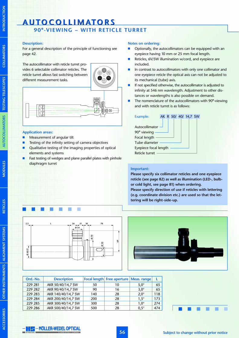
AUTOCO L L I MATOR SAUTOCO L L I MATOR S
AUTOCOLLIM
ATORS
90°-VIEWING – WITH RETICLE TURRET
56
Important:
Please specify six collimator reticles and one eyepiece
reticle (see page 82) as well as illumination (LED-, bulb-
or cold light, see page 81) when ordering.
Please specify direction of use if reticles with lettering
(e.g. coordinate division etc.) are used so that the let-
tering will be right-side-up.
Subject to change without prior notice
5
5
5
5
10
10
10
10
12
3
45
67
8
2,5 L
Ø7
0
Ø3
0
Ø 34
Ø4
0f7
26 21 18 78
69
229 281 AKR 50/40/14,7 SW 50 10 5,0° 65
229 282 AKR 90/40/14,7 SW 90 16 3,0° 65
229 283 AKR 140/40/14,7 SW 140 28 2,0° 118
229 284 AKR 200/40/14,7 SW 200 28 1,5° 173
229 285 AKR 300/40/14,7 SW 300 28 1,0° 274
229 286 AKR 500/40/14,7 SW 500 28 0,5° 474
Ord.-No. Description Focal length Free aperture Meas. range L
Description:
For a general description of the principle of functioning seepage 42.
The autocollimator with reticle turret pro-vides 6 selectable collimator reticles. Thereticle turret allows fast switching betweendifferent measurement tasks.
Application areas:
� Measurement of angular tilt� Testing of the infinity setting of camera objectives� Qualitative testing of the imaging properties of optical
elements and systems� Fast testing of wedges and plane parallel plates with pinhole
diaphragm turret
Notes on ordering:
� Optionally, the autocollimators can be equipped with aneyepiece having 10 mm or 25 mm focal length.
� Reticles, 6V/5W illumination w/cord, and eyepiece areincluded.
� In contrast to autocollimators with only one collimator andone eyepiece reticle the optical axis can not be adjusted toits mechanical (tube) axis.
� If not specified otherwise, the autocollimator is adjusted toinfinity at 546 nm wavelength. Adjustment to other dis-tances or wavelengths is also possible on demand.
� The nomenclature of the autocollimators with 90°-viewingand with reticle turret is as follows:
Example: AK R 50/ 40/ 14,7 SW
Autocollimator90° viewingFocal lengthTube diameterEyepiece focal lengthReticle turret
COLLIM
ATORS
INTRODUCTIO
NTESTIN
GTELE
SCOPES
MODULE
SRETICLE
SALIGNMENTSYSTEMS
OTHERIN
STRUMENTS
ACCESSORIES

AUTOCOLLIM
ATORS
57
Ø7
0
Ø3
0
a
d ce2c e1 d
4
ØD
26
69
b
27
117
Ø 34
Ø7
0
Ø3
0
Ø 34
26 21 18 80,6
69
L
Ø5
4
Ø6
5f7
62
www.moeller-wedel-optical.com
229 287 AKR 300/65/14,7 SW 300 50 1,0° 65
229 288 AKR 500/65/14,7 SW 500 50 0,5° 65
229 290 AKR 500T/65/14,7 SW 500 50 0,5° 118
Ord.-No. Description Focal length Free aperture Meas. range L
229 292 AKR 600/128/14,7 SW 600 100 0,40° Ø 128 f7 530 46 – 58 154 78
229 293 AKR 1100/105/14,7 SW 1100 78 0,25° Ø 105 f7 1045 66 50 30 165 100
Ord.-No. Description Focal length Free aperture Meas. range D a cb d e1 e2
COLLIM
ATORS
INTRODUCTIO
NTESTIN
GTELE
SCOPES
MODULE
SRETICLE
SALIGNMENTSYSTEMS
OTHERIN
STRUMENTS
ACCESSORIES

AUTOCO L L I MATOR SAUTOCO L L I MATOR S
AUTOCOLLIM
ATORS
WITH CCD-CAMERA MOUNT
58
Important:
Please specify collimator reticle (see page 82) as well as
illumination (LED-, bulb- or cold light, see page 81) when
ordering.
Subject to change without prior notice
229 421 AKR 50/40/CCD 50 10 x:4,50° y:3,20° 65
229 422 AKR 90/40/CCD 90 16 x:2,50° y:1,80° 65
229 423 AKR 140/40/CCD 140 28 x:1,60° y:1,20° 118
229 424 AKR 200/40/CCD 200 28 x:1,10° y:0,80° 173
229 425 AKR 300/40/CCD 300 28 x:0,75° y:0,60° 274
229 426 AKR 500/40/CCD 500 28 x:0,45° y:0,30° 474
Ord.-No. Description Focal length Free aperture Meas. range* L
Description:
For a general description of the principle of functioning seepage 42.
The principle, function and layout resemble the autocollimatorwith 90°-viewing (see page 46). The eyepiece and the eyepiecereticle are replaced by a mount for a CCD-camera and the auto-collimation image is directly imaged on the camera chip whenthe camera is mounted. With no eyepiece reticle the displace-ment of the return image is measured on a video monitor orusing a computer, frame grabber and software (see page 106).
Application areas:
� Measurement of angular tilt� Measurement of parallelism of plane plates� Adjustment of optical elements� Qualitative testing of the imaging properties of optical
elements and systems
Notes on ordering:
� One Reticle and 6V/5W illumination w/cord are included.
More notes on ordering:
� CCD-camera and computer hardware/software are NOT
included.
� As this type of autocollimator does not have an eyepiecereticle a direct measurement of the reticle displacement isimpossible. Additional computer with software and framegrabber is needed.
� For angular measurement the autocollimator should beequipped with a negative crosshair reticle (see page 83).For testing of imaging quality use resolution target orSiemens Star (see page 87).
� If not specified otherwise, the autocollimator is adjusted toinfinity at 546 nm wavelength. Adjustment to other dis-tances or wavelengths is also possible on demand.
� The nomenclature of the autocollimators with CCD-cameramount is as follows:
Example: AK R 50/ 40/ CCD
Autocollimator90° viewingFocal lengthTube diameterCCD-Camera mount
5 41 16 7 46,5 27,5
Ø4
0f7
Ø3
3
Ø31
Ø3
0
Ø2
4,5
¨4
0
17L2,5
1´´32
4,5
COLLIM
ATORS
INTRODUCTIO
NTESTIN
GTELE
SCOPES
MODULE
SRETICLE
SALIGNMENTSYSTEMS
OTHERIN
STRUMENTS
ACCESSORIES

AUTOCOLLIM
ATORS
59
a
d ce2c e1 d
4
ØD
26b 120
¨4
0
1´´32
9 41 97
¨4
0
17
1´´32
4,5
L
Ø5
4
Ø6
5f7
62
www.moeller-wedel-optical.com
229 427 AKR 300/65/CCD 300 50 x:0,75° y:0,60° 233
229 428 AKR 500/65/CCD 500 50 x:0,45° y:0,30° 415
229 429 AKR 500T/65/CCD 500 50 x:0,45° y:0,30° 233
Ord.-No. Description Focal length Free aperture Meas. range* L
229 432 AKR 600/128/CCD 600 100 x:0,35° y:0,25° Ø 128 f7 530 46 – 58 154 78
229 433 AKR 1100/105/CCD 1100 78 x:0,20° y:0,15° Ø 105 f7 1045 66 50 30 165 100
Ord.-No. Description Focal length Free aperture Meas. range* D a cb d e1 e2
COLLIM
ATORS
INTRODUCTIO
NTESTIN
GTELE
SCOPES
MODULE
SRETICLE
SALIGNMENTSYSTEMS
OTHERIN
STRUMENTS
ACCESSORIES
* with 2/3” CCD-Kamera

AUTOCO L L I MATOR SAUTOCO L L I MATOR S
AUTOCOLLIM
ATORS
FOCUSABLE – STRAIGHT VIEWING
60
Ø 33
Ø3
4
27
117
26 69
Ø4
0
Ø4
0f7
Ø5
2
65
L 38 12
Ø3
3
229 501 AKGV 90/40/14,7/±6 90 16 ±6 3,0° –∞...–1,25 m 77±61,40 m...+∞
229 502 AKGV 90/40/14,7/+12 90 16 +12 3,0° 0,80 m...+∞ 71+12
229 503 AKGV 90/40/14,7/–12 90 16 –12 3,0° –∞...–0,60 m 83–12
229 504 AKGV 140/40/14,7/±6 140 28 ±6 2,0° –∞...–3,10 m 77±63,30 m...+∞
229 505 AKGV 140/40/14,7/+12 140 28 +12 2,0° 1,70 m...+∞ 71+12
229 506 AKGV 140/40/14,7/–12 140 28 –12 2,0° –∞...–1,40 m 83–12
Ord.-No. Description Focallength
Freeaperture
Meas.range
Distancerange
LTubeextension
Description:
For a general description of the principle of functioning offocusable autocollimators see page 43.
Application areas:
� Measurement of angular tilt� Qualitative testing of the imaging properties of optical
elements and systems� Measurement of large radii of curvature� Infinity adjustment to other wavelengths
Notes on ordering:
� Optionally, the autocollimators can be equipped with aneyepiece having 10 mm or 25 mm focal length.
� Two reticles, 6V/5W illumination w/cord, and eyepiece areincluded.
� The nomenclature of the adjustable autocollimators withstraight viewing is as follows:
Example: AK G V 90/ 40/ 14,7 ±6
AutocollimatorStraight viewingVariableFocal lengthTube diameterEyepiece focal lengthTube extension in mm
Subject to change without prior notice
Impotant:
Please specify collimator reticle and eyepiece reticle
(see page 82) as well as illumination (LED-, bulb- or cold
light, see page 81) when ordering.
(+)a
(+)z´f
(–)a (–)z´
COLLIM
ATORS
INTRODUCTIO
NTESTIN
GTELE
SCOPES
MODULE
SRETICLE
SALIGNMENTSYSTEMS
OTHERIN
STRUMENTS
ACCESSORIES

AUTOCOLLIM
ATORS
61
1045
620 30 215
5L
50 100 30
4
Ø 40
10
2
Ø10
5f7
26 69
11727
Ø3
4
Ø6
5f7
Ø6
5f7
1,5
Ø6
8
29
6
10
2
Ø 40
A
B L 6926
117
Ø 33 27
Ø3
3
Ø3
4Ø
34
229 516 AKGV 1100/105/14,7/±50 1100 78 ±50 0,25° –∞...–23,7 m 202±5025,8 m...+∞
229 517 AKGV 1100/105/14,7/+100 1100 78 +100 0,25° 13,2 m...+∞ 202+100
229 518 AKGV 1100/105/14,7/–100 1100 78 –100 0,25° –∞...–12,0 m 202–100
Ord.-No. Description Focallength
Freeaperture
Meas.range
Distancerange
LTubeextension
229 507 AKGV 300/65/14,7/±25 300 50 ±25 1,0° –∞...–3,4 m 220 245 87±253,8 m...+∞
229 508 AKGV 300/65/14,7/+50 300 50 +50 1,0° 2,1 m...+∞ 220 270 62+50
229 509 AKGV 300/65/14,7/–50 300 50 –50 1,0° –∞...–1,5 m 220 220 112–50
229 510 AKGV 500/65/14,7/±50 500 50 ±50 0,5° –∞...–4,5 m 310 360 112±505,4 m...+∞
229 511 AKGV 500/65/14,7/+100 500 50 +100 0,5° 3,0 m...+∞ 310 410 62+100
229 512 AKGV 500/65/14,7/–100 500 50 –100 0,5° –∞...–1,5 m 310 310 162–100
Ord.-No. Description Focallength
Freeaperture
Meas.range
Distancerange
LA BTubeextension
www.moeller-wedel-optical.com
COLLIM
ATORS
INTRODUCTIO
NTESTIN
GTELE
SCOPES
MODULE
SRETICLE
SALIGNMENTSYSTEMS
OTHERIN
STRUMENTS
ACCESSORIES

AUTOCO L L I MATOR SAUTOCO L L I MATOR S
AUTOCOLLIM
ATORS
FOCUSABLE – 90°-VIEWING
62
Ø4
0f7
65
L 38 12 26 117
69
Ø 34
Ø 33
Ø4
0
Ø5
2
Ø3
3
Description:
For a general description of the principle of functioning of focus-able autocollimators see page 43.
This autocollimator is equipped with right angle viewing (seepage 46).
Application areas:
� Adjustment of optical and mechanical systems� Qualitative testing of the imaging properties of optical
elements and systems� Measurement of large radii of curvature� Infinity adjustment to other wavelengths
Notes on ordering:
� Optionally, the autocollimators can be equipped with aneyepiece having 10 mm or 25 mm focal length.
� Two reticles, 6V/5W illumination w/cord, and eyepiece areincluded.
� The nomenclature of the adjustable autocollimators with90°-viewing is as follows:
Example: AK R V 90/ 40/ 14,7 ±6
Autocollimator90° viewingVariableFocal lengthTube diameterEyepiece focal lengthTube extension in mm
(–)z´
(+)z´
(+)a
f
(–)a
Subject to change without prior notice
229 701 AKRV 90/40/14,7/±6 90 16 ±6 3,0° –∞...–1,25 m 77±61,40 m...+∞
229 702 AKRV 90/40/14,7/+12 90 16 +12 3,0° 0,80 m...+∞ 71+12
229 703 AKRV 90/40/14,7/–12 90 16 –12 3,0° –∞...–0,60 m 83–12
229 704 AKRV 140/40/14,7/±6 140 28 ±6 2,0° –∞...–3,10 m 77±63,30 m...+∞
229 705 AKRV 140/40/14,7/+12 140 28 +12 2,0° 1,70 m...+∞ 71+12
229 706 AKRV 140/40/14,7/–12 140 28 –12 2,0° –∞...–1,40 m 83–12
Ord.-No. Description Focallength
Freeaperture
Meas.range
Distancerange
LTubeextension
Important:
Please specify collimator reticle and eyepiece reticle
(see page 82) as well as illumination (LED-, bulb- or cold
light, see page 81) when ordering.
Please specify direction of use if reticles with lettering
(e.g. coordinate division etc.) are used so that the let-
tering will be right-side-up.
COLLIM
ATORS
INTRODUCTIO
NTESTIN
GTELE
SCOPES
MODULE
SRETICLE
SALIGNMENTSYSTEMS
OTHERIN
STRUMENTS
ACCESSORIES

AUTOCOLLIM
ATORS
63
1045
620 30 215
5 L
50 100 30
4
Ø 40
10
2
Ø10
5f7
26 117
Ø3
3
69
Ø 34
29
Ø6
5f7
1,5
Ø6
8
29
6
10
2
Ø 40
A
B L 26 117
Ø3
3
69
Ø 34
Ø 33
www.moeller-wedel-optical.com
229 716 AKRV 1100/105/14,7/±50 1100 78 ±50 0,25° –∞...–23,7 m 177±5025,8 m...+∞
229 717 AKRV 1100/105/14,7/+100 1100 78 +100 0,25° 13,2 m...+∞ 177+100
229 718 AKRV 1100/105/14,7/–100 1100 78 –100 0,25° –∞...–12,0 m 177–100
Ord.-No. Description Focallength
Freeaperture
Meas.range
Distancerange
LTubeextension
229 707 AKRV 300/65/14,7/±25 300 50 ±25 1,0° –∞...–3,4 m 220 245 87±253,8 m...+∞
229 708 AKRV 300/65/14,7/+50 300 50 +50 1,0° 2,1 m...+∞ 220 270 62+50
229 709 AKRV 300/65/14,7/–50 300 50 –50 1,0° –∞...–1,5 m 220 220 112–50
229 710 AKRV 500/65/14,7/±50 500 50 ±50 0,5° –∞...–4,5 m 310 360 112±505,4 m...+∞
229 711 AKRV 500/65/14,7/+100 500 50 +100 0,5° 3,0 m...+∞ 310 410 62+100
229 712 AKRV 500/65/14,7/–100 500 50 –100 0,5° –∞...–1,5 m 310 310 162–100
Ord.-No. Description Focallength
Freeaperture
Meas.range
Distancerange
LA BTubeextension
COLLIM
ATORS
INTRODUCTIO
NTESTIN
GTELE
SCOPES
MODULE
SRETICLE
SALIGNMENTSYSTEMS
OTHERIN
STRUMENTS
ACCESSORIES

AUTOCO L L I MATOR SAUTOCO L L I MATOR S
AUTOCOLLIM
ATORS
FOCUSABLE – STRAIGHT VIEWING WITH DOUBLE MICROMETER
64 Subject to change without prior notice
Ø4
0
Ø4
0f7
Ø5
2
65
L 38 12 6926
Ø 33
117
(+)a
(+)z´
(–)z´
f
(–)a
Description:
For a general description of the principle of functioning of focus-able autocollimators see page 43.
Additionally, micrometers allow the direct measurement of eye-piece reticle movement. The scale division (SD) of the micro-meter drums is 5 µm.
Application areas:
� Measurement of angular tilt� Qualitative testing of the imaging properties of optical
elements and systems� Measurement of large radii of curvature� Infinity adjustment to other wavelengths� Adjustment of optical and mechanical systems
Notes on ordering:
� Optionally, the autocollimators can be equipped with aneyepiece having 10 mm or 25 mm focal length.
� Two reticles, 6V/5W illumination w/cord, and eyepiece areincluded.
� The nomenclature of the adjustable autocollimators withstraight viewing and with double micrometer is as follows:
Example: AK G V 90/ 40/ 14,7 ±6 MD
AutocollimatorStraight viewingVariableFocal lengthTube diameterEyepiece focal lengthTube extension in mmDouble micrometer
Important:
Please specify collimator reticle and eyepiece reticle
(see page 82) as well as illumination (LED-, bulb- or cold
light, see page 81) when ordering.
COLLIM
ATORS
INTRODUCTIO
NTESTIN
GTELE
SCOPES
MODULE
SRETICLE
SALIGNMENTSYSTEMS
OTHERIN
STRUMENTS
ACCESSORIES
229 631 AKGV 90/40/14,7/±6 MD 90 16 ±6 3,0° 5,5” –∞...–1,25 m 77±61,40 m...+∞
229 632 AKGV 90/40/14,7/+12 MD 90 16 +12 3,0° 5,5” 0,80 m...+∞ 71+12
229 633 AKGV 90/40/14,7/–12 MD 90 16 –12 3,0° 5,5” –∞...–0,60 m 83–12
229 634 AKGV 140/40/14,7/±6 MD 140 28 ±6 2,0° 3,5” –∞...–3,10 m 77±63,30 m...+∞
229 635 AKGV 140/40/14,7/+12 MD 140 28 +12 2,0° 3,5” 1,70 m...+∞ 71+12
229 636 AKGV 140/40/14,7/–12 MD 140 28 –12 2,0° 3,5” –∞...–1,40 m 83–12
Ord.-No. Description Focallength
Freeaperture
Meas.range
Distancerange
LTubeextension
SD

AUTOCOLLIM
ATORS
65www.moeller-wedel-optical.com
1045
620 30 215
5 L
50 100 30
4
Ø 40
10
2
Ø10
5f7
26 69
117
Ø3
4
Ø6
5f7
1,5
Ø6
8
29
6
A
B L 6926
Ø 33
117
COLLIM
ATORS
INTRODUCTIO
NTESTIN
GTELE
SCOPES
MODULE
SRETICLE
SALIGNMENTSYSTEMS
OTHERIN
STRUMENTS
ACCESSORIES
229 642 AKGV 1100/105/14,7/±50 MD 1100 78 ±50 0,25° 0,5” –∞...–23,70 m 202±5025,80 m...+∞
229 646 AKGV 1100/105/14,7/+100 MD 1100 78 +100 0,25° 0,5” 13,20 m...+∞ 202+100
229 643 AKGV 1100/105/14,7/–100 MD 1100 78 –100 0,25° 0,5” –∞...–12,00 m 202–100
Ord.-No. Description Focallength
Freeaperture
Meas.range
Distancerange
LTubeextension
229 640 AKGV 300/65/14,7/±25 MD 300 50 ±25 1,0° 2,0” –∞...–3,4 m 220 245 220±253,8 m...+∞
229 638 AKGV 300/65/14,7/+50 MD 300 50 +50 1,0° 2,0” 2,1 m...+∞ 220 270 195+50
229 639 AKGV 300/65/14,7/–50 MD 300 50 –50 1,0° 2,0” –∞...–1,5 m 220 220 245–50
229 641 AKGV 500/65/14,7/±50 MD 500 50 ±50 0,5° 1,0” –∞...–4,5 m 310 360 245±505,4 m...+∞
229 644 AKGV 500/65/14,7/+100 MD 500 50 +100 0,5° 1,0” 3,0 m...+∞ 310 410 195+100
229 645 AKGV 500/65/14,7/–100 MD 500 50 –100 0,5° 1,0” –∞...–1,5 m 310 310 295–100
Ord.-No. Description Focallength
Freeaperture
Meas.range
Distancerange
LA BTubeextension
SD
SD

AUTOCO L L I MATOR SAUTOCO L L I MATOR S
AUTOCOLLIM
ATORS
FOCUSABLE – STRAIGHT VIEWING WITH DIG ITAL DOUBLE
66 Subject to change without prior notice
69
Ø 40
Ø3
4
35
13
85
7
2657138
89
Ø61
Ø76
Ø4
0
Ø4
0f7
Ø5
2
65
L 38 12
229 581 AKGV 90/40/14,7/±6 MDD 90 16 ±6 3,0° 1,0” –∞...–1,25 m 77±61,40 m...+∞
229 582 AKGV 90/40/14,7/+12 MDD 90 16 +12 3,0° 1,0” 0,80 m...+∞ 71+12
229 583 AKGV 90/40/14,7/–12 MDD 90 16 –12 3,0° 1,0“ –∞...–0,60 m 83–12
229 584 AKGV 140/40/14,7/±6 MDD 140 28 ±6 2,0° 1,0” –∞...–3,10 m 77±63,30 m...+∞
229 585 AKGV 140/40/14,7/+12 MDD 140 28 –12 2,0° 1,0” 1,70 m...+∞ 71–12
229 586 AKGV 140/40/14,7/–12 MDD 140 28 –12 2,0° 1,0” –∞...–1,40 m 83–12
Ord.-No. Description Focallength
Freeaperture
Meas.range
Resolution Distancerange
LTubeextension
Description:
For a general description of the principle of functioning of focus-able autocollimators see page 43.In place of the micrometer drums above, optionally, program-mable digital gauges allow direct reading of the tilting anglein arcsec or mrad.
Application areas:
� Measurement of angular tilt� Adjustment of optical and mechanical systems� Qualitative testing of the imaging properties of optical
elements and systems� Measurement of large radii of curvature� Infinity adjustment to other wavelengths
Notes on ordering:
� Optionally, the autocollimators can be equipped with aneyepiece having 10 mm or 25 mm focal length.
� Two reticles, 6V/5W illumination w/cord, and eyepiece areincluded.
� Specify the unit of display of the digital gauges (mm,arcsec, milliradians).
� The nomenclature of the adjustable autocollimators withdigital double micrometer is as follows:
Example: AK G V 90/ 40/ 14,7 ±6 MDD
AutocollimatorStraight viewingVariableFocal lengthTube diameterEyepiece focal lengthTube extension in mmDigital double micrometer
0000,0
0000,0
0000,0
(+)a
(+)z´
(–)z´
f
(–)a
Important:
Please specify collimator reticle and eyepiece reticle
(see page 82) as well as illumination (LED-, bulb- or cold
light, see page 81) when ordering.
COLLIM
ATORS
INTRODUCTIO
NTESTIN
GTELE
SCOPES
MODULE
SRETICLE
SALIGNMENTSYSTEMS
OTHERIN
STRUMENTS
ACCESSORIES

AUTOCOLLIM
ATORS
MICROMETER
67www.moeller-wedel-optical.com
229 596 AKGV 1100/105/14,7/±50 MDD 1100 78 ±50 0,5° 0,1 arcsec –∞...–23,7 m 202±5025,8 m...+∞
229 597 AKGV 1100/105/14,7/+100 MDD 1100 78 +100 0,5° 0,1 arcsec 13,2 m...+∞ 202+100
229 598 AKGV 1100/105/14,7/–100 MDD 1100 78 –100 0,5° 0,5 arcsec –∞...–12,0 m 202–100
Ord.-No. Description Focallength
Freeaperture
Meas.range
Resolution Distancerange
LTubeextension
50
4
Ø10
5f7
Ø 76
57 1045
620 30 215
5 L
100 30 26 69
117
Ø 40
35
138
Ø6
5f7
1,5
57138
89
Ø61 Ø76
69
Ø 40
Ø3
4
35
13
85
7
68
29
6
A
B L 26
229 587 AKGV 300/65/14,7/±25 MDD 300 50 ±25 1,0° 0,5 arcsec –∞...–3,4 m 220 245 87±253,8 m...+∞
229 588 AKGV 300/65/14,7/+50 MDD 300 50 +50 1,0° 0,5 arcsec 2,1 m...+∞ 220 270 62+50
229 589 AKGV 300/65/14,7/–50 MDD 300 50 –50 1,0° 0,5 arcsec –∞...–1,5 m 220 220 112–50
229 590 AKGV 500/65/14,7/±50 MDD 500 50 ±50 0,5° 0,2 arcsec –∞...–4,5 m 310 360 112±505,4 m...+∞
229 591 AKGV 500/65/14,7/+100 MDD 500 50 +100 0,5° 0,2 arcsec 3,0 m...+∞ 310 410 62+100
229 592 AKGV 500/65/14,7/–100 MDD 500 50 –100 0,5° 0,2 arcsec –∞...–1,5 m 310 310 162–100
Ord.-No. Description Focallength
Freeaperture
Meas.range
Resolution Distancerange
LA BTubeextension
COLLIM
ATORS
INTRODUCTIO
NTESTIN
GTELE
SCOPES
MODULE
SRETICLE
SALIGNMENTSYSTEMS
OTHERIN
STRUMENTS
ACCESSORIES

AUTOCO L L I MATOR SAUTOCO L L I MATOR S
AUTOCOLLIM
ATORS
FOCUSABLE – 90°-VIEWING WITH RETICLE TURRET
68
Ø4
0f7
Ø5
2
65
L 38 12 26 117
69
Ø 34
Ø 33
Ø7
0
Subject to change without prior notice
229 781 AKRV 90/40/14,7/±6 SW 90 16 ±6 3,0° –∞...–1,25 m 77±61,40 m...+∞
229 782 AKRV 90/40/14,7/+12 SW 90 16 +12 3,0° 0,80 m...+∞ 71+12
229 783 AKRV 90/40/14,7/–12 SW 90 16 –12 3,0° –∞...–0,60 m 83–12
229 784 AKRV 140/40/14,7/±6 SW 140 28 ±6 2,0° –∞...–3,10 m 77±63,30 m...+∞
229 785 AKRV 140/40/14,7/+12 SW 140 28 +12 2,0° 1,70 m...+∞ 71+12
229 786 AKRV 140/40/14,7/–12 SW 140 28 –12 2,0° –∞...–1,40 m 83–12
Ord.-No. Description Focallength
Freeaperture
Meas.range
Distancerange
LTubeextension
Description:
For a general description of the principle of functioning of focus-able autocollimators see page 43.
Additionally, the autocollimator provides 6selectable collimator reticles. The reticle tur-ret allows fast switching between differentmeasuring tasks.
Application areas:
� Adjustment of optical and mechanical systems� Qualitative testing of the imaging properties of optical
elements and systems� Measurement of large radii of curvature� Infinity adjustment to other wavelengths
Notes on ordering:
� Optionally, the autocollimators can be equipped with aneyepiece having 10 mm or 25 mm focal length.
� The reticles, 6V/5W illumination w/cord, and eyepiece areincluded.
� The nomenclature of the adjustable autocollimators with90°-viewing and with reticle turret is as follows:
Example: AK R V 90/ 40/ 14,7 ±6 SW
Autocollimator90° viewingVariableFocal lengthTube diameterEyepiece focal lengthTube extension in mmReticle turret
Important:
Please specify six collimator reticles and one eyepiece
reticle (see page 82) as well as illumination (LED-, bulb-
or cold light, see page 81) when ordering.
Please specify direction of use if reticles with lettering
(e.g. coordinate division etc.) are used so that the let-
tering will be right-side-up.
(+)a
(+)z´
(–)z´
f
(–)a
COLLIM
ATORS
INTRODUCTIO
NTESTIN
GTELE
SCOPES
MODULE
SRETICLE
SALIGNMENTSYSTEMS
OTHERIN
STRUMENTS
ACCESSORIES
5
5
5
5
10
10
10
10
12
3
45
67
8

AUTOCOLLIM
ATORS
69
1045
620 30 215
5 L
50 100 30
4
Ø 40
10
2
Ø10
5f7
26 117
69
Ø 34
29
Ø7
0
Ø7
0
Ø6
5f7
1,5
Ø6
8
29
6
10
2
Ø 40
A
B L 26 117
69
Ø 34
Ø 33
www.moeller-wedel-optical.com
229 796 AKRV 1100/105/14,7/±50 SW 1100 78 ±50 0,5° –∞...–23,7 m 202±5025,8 m...+∞
229 797 AKRV 1100/105/14,7/+100 SW 1100 78 +100 0,5° 13,2 m...+∞ 202+100
229 798 AKRV 1100/105/14,7/–100 SW 1100 78 –100 0,5° –∞...–12,0 m 202–100
Ord.-No. Description Focallength
Freeaperture
Meas.range
Distancerange
LTubeextension
229 787 AKRV 300/65/14,7/±25 SW 300 50 ±25 1,0° –∞...–3,4 m 220 245 87±253,8 m...+∞
229 788 AKRV 300/65/14,7/+50 SW 300 50 +50 1,0° 2,1 m...+∞ 220 270 62+50
229 789 AKRV 300/65/14,7/–50 SW 300 50 –50 1,0° –∞...–1,5 m 220 220 112–50
229 790 AKRV 500/65/14,7/±50 SW 500 50 ±50 0,5° –∞...–4,5 m 310 360 112±505,4 m...+∞
229 791 AKRV 500/65/14,7/+100 SW 500 50 +100 0,5° 3,0 m...+∞ 310 410 62+100
229 792 AKRV 500/65/14,7/–100 SW 500 50 –100 0,5° –∞...–1,5 m 310 310 162–100
Ord.-No. Description Focallength
Freeaperture
Meas.range
Distancerange
LA BTubeextension
COLLIM
ATORS
INTRODUCTIO
NTESTIN
GTELE
SCOPES
MODULE
SRETICLE
SALIGNMENTSYSTEMS
OTHERIN
STRUMENTS
ACCESSORIES

AUTOCO L L I MATOR SAUTOCO L L I MATOR S
AUTOCOLLIM
ATORS
FOCUSABLE – WITH CCD-CAMERA MOUNT
70
Ø4
0
Ø4
0f7
Ø5
2
65
L 38 12 41 16 7 47 28
Ø3
3
Ø31
Ø3
0
Ø2
5
¨4
0
17
1´´32 4,5
Subject to change without prior notice
229 471 AKRV 90/40/±6 CCD 90 16 ±6 x:2,50° y:1,80° –∞...–1,25 m 77±61,40 m...+∞
229 472 AKRV 90/40/+12 CCD 90 16 +12 x:2,50° y:1,80° 0,80 m...+∞ 71+12
229 473 AKRV 90/40/–12 CCD 90 16 –12 x:2,50° y:1,80° –∞...–0,60 m 83–12
229 474 AKRV 140/40/±6 CCD 140 28 ±6 x:1,60° y:1,20° –∞...–3,10 m 77±63,30 m...+∞
229 475 AKRV 140/40/+12 CCD 140 28 +12 x:1,60° y:1,20° 1,70 m...+∞ 71+12
229 476 AKRV 140/40/–12 CCD 140 28 –12 x:1,60° y:1,20° ∞...–1,40 m 83–12
Impotant:
Please specify collimator reticle (see page 82) as well
as illumination (LED-, bulb- or cold light, see page 81)
when ordering.
Description:
For a general description of the principle of functioning of focus-able autocollimators see page 43.
The eyepiece and the eyepiece reticle are replaced by a mountfor a C-Mount-CCD-camera and the autocollimation image isdirectly imaged on the camera chip when it is mounted.
Application areas:
� Adjustment of optical and mechanical systems� Qualitative testing of the imaging properties of optical
elements and systems� Measurement of large radii of curvature� Infinity adjustment to other wavelengths
Notes on ordering:
� The CCD-camera and computer hardware/software are
NOT included.
� As this type of autocollimator does not have an eyepiecereticle a direct measurement of the reticle displacement isimpossible. Additional computer with software and framegrabber is needed.
More notes on ordering:
� Collimator reticle and 6V/5W illumination w/cord areincluded.
� For angular measurement the autocollimator should beequipped with a negative crosshair reticle (see page 83).For testing of imaging quality use resolution target orSiemens Star (see page 87).
� The nomenclature of the adjustable autocollimators withCCD-camera mount is as follows:
Example: AK R V 90/ 40/ ±6 CCD
Autocollimator90° viewingVariableFocal lengthTube diameterTube extension in mmCCD-Camera mount
(+)a
(+)z´
(–)z´
f
(–)a
COLLIM
ATORS
INTRODUCTIO
NTESTIN
GTELE
SCOPES
MODULE
SRETICLE
SALIGNMENTSYSTEMS
OTHERIN
STRUMENTS
ACCESSORIES
Ord.-No. Description Focallength
Freeaperture
Tubeextension
Meas. range* Distancerange
L

AUTOCOLLIM
ATORS
71
1045
620 30 215
5L
50 100 30
4
Ø 40
10
2
Ø10
5f7
26 120
29
1´´32
Ø6
5f7
1,5
Ø6
8
29
6
10
2
Ø 40
A
B L 26 120
41 16 7 47 28
Ø3
3Ø
31
Ø3
0
Ø2
5
¨4
0
1´´32 4,5
www.moeller-wedel-optical.com
229 477 AKRV 300/65/±25 CCD 300 50 ±25 x:2,50° y:1,80° –∞...–3,4 m 220 245 87±253,8 m...+∞
229 478 AKRV 300/65/+50 CCD 300 50 +50 x:2,50° y:1,80° 2,1 m...+∞ 220 270 62+50
229 479 AKRV 300/65/–50 CCD 300 50 –50 x:2,50° y:1,80° –∞...–1,5 m 220 220 112–50
229 480 AKRV 500/65/±50 CCD 500 50 ±50 x:2,50° y:1,80° –∞...–4,5 m 310 360 112±505,4 m...+∞
229 481 AKRV 500/65/+100 CCD 500 50 +100 x:2,50° y:1,80° 3,0 m...+∞ 310 410 62+100
229 482 AKRV 500/65/–100 CCD 500 50 –100 x:2,50° y:1,80° –∞...–1,5 m 310 310 162–100
Ord.-No. Description Focallength
Freeaperture
Meas. range* Distancerange
LA BTubeextension
COLLIM
ATORS
INTRODUCTIO
NTESTIN
GTELE
SCOPES
MODULE
SRETICLE
SALIGNMENTSYSTEMS
OTHERIN
STRUMENTS
ACCESSORIES
* mit 2/3” CCD-Kamera
229 486 AKRV 1100/105/±50 CCD 1100 78 ±50 x:0,20° y:0,14° –∞...–23,7 m 177±5025,8 m...+∞
229 487 AKRV 1100/105/+100 CCD 1100 78 +100 x:0,20° y:0,14° 13,2 m...+∞ 117+12
229 488 AKRV 1100/105/–100 CCD 1100 78 –100 x:0,20° y:0,14° –∞...–12,0 m 117–12
Ord.-No. Description Focallength
Freeaperture
Meas. range* Distancerange
LTubeextension

MODU L AR COMPON ENT SMODU L AR COMPON ENT SINTRODUCTION
72
Modular components
Autocollimators, collimators and testing telescopesby MÖLLER-WEDEL OPTICAL are of modular design,the components are freely interchangeable and, ofcourse, precisely matched to each other. Free inter-changeability allows manifold combination possibili-ties and ensures economic solution of problems.The basic component is the objective tube whichis available in great variety of different focal lengths
and tube diameters. Eyepieces, adapter sleeves withreticle and illuminator or autocollimation eyepieces,can also be attached.So one can combine modules to make a telescope,a collimator or even an autocollimator.Minimum effort is needed for setting up differentcombinations as the basic components are the samein any configuration.
Subject to change without prior notice
AUTOCOLLIM
ATORS
COLLIM
ATORS
INTRODUCTIO
NTESTIN
GTELE
SCOPES
MODULE
SRETICLE
SALIGNMENTSYSTEMS
OTHERIN
STRUMENTS
ACCESSORIES
Reticle sleeve with eyepiece
Reticle adapter sleeve with reticle and eyepieceforms with an objective tube a testing telescope.
Autocollimation eyepiece
The autocollimation eyepiece with illumination andeyepiece forms with an objective tube an autocolli-mator.
Light source
For operation of collimators and autocollimatorsa light source is necessary.
Reticle sleeve with illumination
Reticle adapter sleeve with illumination forms withan objective tube a collimator.

AUTOCOLLIM
ATORS
73
Supplementary extension to other measurement taskscould not be simpler. All modular components areavailable seperately. The user is free to set up thecomponents as she or he wishes.Due to the way they work, collimators and telescopesrequire one reticle, autocollimators require two.
www.moeller-wedel-optical.com
COLLIM
ATORS
INTRODUCTIO
NTESTIN
GTELE
SCOPES
MODULE
SRETICLE
SALIGNMENTSYSTEMS
OTHERIN
STRUMENTS
ACCESSORIES
Objectiv tube
Objective tubes are the core components of all testing telescopes, collimators andautocollimators. The cylindrical tube is hard chromed for high wear-resistance. Allobjective tubes of a standard design are fitted with two-element objectives (achro-mats). By interchanging the objective tube (alteration of the focal length) the mea-suring range and the accuracy is altered.
Objective tubes are available either with fixed distance settings or with variablefocus adjustment. The variable focus adjustment is realized by tube extension.Focusable objective tubes are used where discrete distances have to be focused orif the collimators/telescopes/autocollimators should be used at other wavelengthsthan 546 nm.

74 Subject to change without prior notice
AUTOCOLLIM
ATORS
COLLIM
ATORS
INTRODUCTIO
NTESTIN
GTELE
SCOPES
MODULE
SRETICLE
SALIGNMENTSYSTEMS
OTHERIN
STRUMENTS
ACCESSORIES
2,5 L
M3
6x
0,7
5
Ø4
0f7
1106
50 165 304
Ø10
5f7
30 100 50 61
M3
6x
0,7
5
2,5
Ø6
5f7
L
Ø5
4
61,5
M3
6x
0,7
5
M3
6x
0,7
558 78 46
578
581544
Ø12
8f7
2,5
Ø6
5f7
233 45
60o°
Ø6
7
M36 x 0,75
Fig. 1
Fig. 2
Fig. 3
Fig. 4
Fig. 5
MODU L AR COMPON ENT SMODU L AR COMPON ENT SOBJECTIVE TUBES
211 210 Objective tube 90/40 90 16 65 1
211 220 Objective tube 140/40 140 28 118 1
211 230 Objective tube 200/40 200 28 173 1
211 240 Objective tube 300/40 300 28 274 1
211 250 Objective tube 500/40 500 28 474 1
211 301 Objective tube 300/65 300 50 233 2
211 310 Objective tube 500/65 500 50 415 2
211 330 Objective tube 500T/65 500 50 233 2
211 526 Objective tube 500T/65W 500 50 – 3
211 347 Objective tube 600/128 600 100 – 4
211 401 Objective tube 1100/105 1100 78 – 5
Ord.-No. Description Focal length Free aperture L Fig.

AUTOCOLLIM
ATORS
75www.moeller-wedel-optical.com
COLLIM
ATORS
INTRODUCTIO
NTESTIN
GTELE
SCOPES
MODULE
SRETICLE
SALIGNMENTSYSTEMS
OTHERIN
STRUMENTS
ACCESSORIES
L 38 12
M3
6x
0,7
5
Ø4
0
Ø5
2
65
Ø4
0f7
Fig. 1
Ø 40
Ø6
5f7
Ø6
8
28
,6
10
2M
36
x0
,75
2,5
B 6 L
A
10
2M
36
x0
,75
L5010030
Ø 40
1045
50 165 30
4
Ø10
5f7
MODU L AR COMPON ENT SMODU L AR COMPON ENT SOBJECTIVE TUBES WITH TUBE EXTENS ION
213 101 Objective tube 90/40 ±6 90 16 ±6 77±6 – – 1
213 102 Objective tube 90/40 +12 90 16 +12 71+12 – – 1
213 103 Objective tube 90/40 –12 90 16 –12 83–12 – – 1
213 104 Objective tube 140/40 ±6 140 28 ±6 77±6 – – 1
213 105 Objective tube 140/40 +12 140 28 +12 71+12 – – 1
213 106 Objective tube 140/40 –12 140 28 –12 83–12 – – 1
213 301 Objective tube 300/65 ±25 300 50 ±25 84±25 220 245 2
213 302 Objective tube 300/65 +50 300 50 +50 59+50 220 270 2
213 303 Objective tube 300/65 –50 300 50 –50 109–50 220 220 2
213 304 Objective tube 500/65 ±50 500 50 ±50 109±50 310 360 2
213 305 Objective tube 500/65 +100 500 50 +100 59+100 310 410 2
213 306 Objective tube 500/65 –100 500 50 –100 159–100 310 310 2
213 316 Objective tube 1100/105 ±50 1100 78 ±50 212±50 – – 3
213 317 Objective tube 1100/105 +100 1100 78 +100 212+100 – – 3
213 318 Objective tube 1100/105 –100 1100 78 –100 212–100 – – 3
Ord.-No. Description Focal length Free aperture LTube extension Fig.A B
Fig 2
Fig 3

MODU L AR COMPON ENT SMODU L AR COMPON ENT SRETICLE SLEEVE WITH ILLUMINATION
76 Subject to change without prior notice
AUTOCOLLIM
ATORS
COLLIM
ATORS
INTRODUCTIO
NTESTIN
GTELE
SCOPES
MODULE
SRETICLE
SALIGNMENTSYSTEMS
OTHERIN
STRUMENTS
ACCESSORIES
215 002 Sleeve with reticle 1217 305 Illumination215 023 Sleeve with reticle turret 2217 305 Illumination215 042 Sleeve with double micrometer 3217 305 Illumination
Ord.-No. Description Fig.
16,7 45,7 46,5 27,5
Ø3
9
Ø3
5
Ø3
0
Ø2
4,5
M3
6x
0,7
5
83
78
M3
6x
0,7
5
Ø3
9
Ø3
5
40,916,7 46,5 27,5
Ø2
4,5
Ø3
9
M3
6x
0,7
5
Ø3
5
Ø7
0
Ø3
0
18
16,7 45,7 46,5 27,5
Ø2
4,5
Fig. 3
Fig. 2
Fig. 1
Notes on ordering:
Please specify reticle(s) (see page 82) and illumination (see
page 81) when ordering.

AUTOCOLLIM
ATORS
MODU L AR COMPON ENT SMODU L AR COMPON ENT SRETICLE SLEEVES WITH EYEPIECE
77www.moeller-wedel-optical.com
COLLIM
ATORS
INTRODUCTIO
NTESTIN
GTELE
SCOPES
MODULE
SRETICLE
SALIGNMENTSYSTEMS
OTHERIN
STRUMENTS
ACCESSORIES
M3
6x
0,7
5
Ø3
9
Ø3
5
Ø3
3,8
Ø 40
57
13
8
35
72,416,7 Fig. 5
Ø3
9
Ø3
3,8
M3
6x
0,7
5
16,7 45,7 26,7
Ø3
5
83 78
Ø 33,8
69
M3
6x
0,7
5
Ø 33,8
69
26
M3
6x
0,7
5
78
83
31,540,916,7
Ø3
5
Ø3
9
Ø3
3,8
M3
6x
0,7
5
215 002 Sleeve with reticle 1217 015 Eyepiece f= 14,7
211 545 90°-sleeve with reticle 2217 015 Eyepiece f= 14,7
215 053 90°-sleeve with double micrometer 3217 015 Eyepiece f= 14,7
215 042 Sleeve with double micrometer 4217 015 Eyepiece f= 14,7
215 051 Sleeve with digital double micrometer 5217 015 Eyepiece f= 14,7
Ord.-No. Description Fig.
Fig. 1
Fig. 4Fig. 3
Fig. 2
Notes on ordering:
Instead of eyepiece f=14,7 mm eyepieces with f=10 mm and
f=25 mm can be used.

MODULAR
COM
PONENTS
MODULAR
COM
PONENTS
AUTOCOLLIM
ATIO
NEYEPIE
CES78
Subject
toch
angewith
outprio
rnotice
AUTOCOLLIMATORS COLLIMATORS INTRODUCTIONTESTING TELESCOPESMODULESRETICLESALIGNMENT SYSTEMSOTHER INSTRUMENTSACCESSORIES
26
69
27
117
Ø 33,8
Ø 33
Ø52
Ø3
3
M 36 x 0,75
117
M 36 x 0,75
26
83
78
69
78
117
M 36 x 0,75
26
69
83
26
117
Ø3
3,8
Ø3
3
Ø 33
69
M 36 x 0,75
Fig.1
Fig.2
Fig.3
Fig.4

AUTOCOLLIM
ATORS
79www.moeller-wedel-optical.com
COLLIM
ATORS
INTRODUCTIO
NTESTIN
GTELE
SCOPES
MODULE
SRETICLE
SALIGNMENTSYSTEMS
OTHERIN
STRUMENTS
ACCESSORIES
219 101 AKG-eyepiece/physical beam splitting/straight viewing/eyepiece f=14,7 mm 1
219 035 AKG-eyepiece/geometrical beam splitting/straight viewing/eyepiece f=14,7 mm 1
219 120 AKR-eyepiece/physical beam splitting/90°- viewing/eyepiece f=14,7 mm 2
219 112 AKG-eyepiece/physical beam splitting/straight viewing/double micrometer/eyepiece f=14,7 mm 3
219 125 AKR-eyepiece/physical beam splitting/90°- viewing/double micrometer/eyepiece f=14,7 mm 4
219 113 AKG-eyepiece/physical beam splitting/straight viewing/digital double micrometer/eyepiece f=14,7 mm 5
219 122 AKR-eyepiece/physical beam splitting/90°- viewing/reticle turret/eyepiece f=14,7 mm 6
219 115 AKR-eyepiece/physical beam splitting/90°- viewing/for direct mounting of a CCD-camera with C-Mount 7
Ord.-No. Description Fig.
57
M3
6x
0,7
5
13
8
89
138 57 26 69
35
Ø 89
Ø3
4
26 21 18 78
Ø 34
M3
6x
0,7
5
69
Ø7
0
Ø3
0
5 41
4,5
¨4
0
Ø3
3
Ø31
Ø3
0
Ø2
4,5
M3
6x
0,7
5
16 7 46,5 27,5
1´´32
Fig. 5
Fig. 6
Fig. 7Notes on ordering:
As standard all autocollimation eyepieces are fit-
ted with illumination 6V/5W.
Optionally, the autocollimation eyepieces can be
equipped with an eyepiece f=10 mm or f=25 mm.
Specify reticles (see page 82) and illumination (see
page 81) when ordering.

80 Subject to change without prior notice
AUTOCOLLIM
ATORS
COLLIM
ATORS
INTRODUCTIO
NTESTIN
GTELE
SCOPES
MODULE
SRETICLE
SALIGNMENTSYSTEMS
OTHERIN
STRUMENTS
ACCESSORIES
18
M2
7x
0,5
M2
7x
0,5
32
M2
7x
0,5
43,1
MODU L AR COMPON ENT SMODU L AR COMPON ENT SEYEPIECES
Description:
The magnification of an autocollimator or telescope can bechanged by changing the eyepieces.The magnification V of a telescope is determined by the relationof objective focal length fOb to eyepiece focal length fOk:
Models:
Three different eyepieces are available: with f=10 mm,f=14,7 mm and f=25 mm.After removing the eyepiece cover ring eyepiece f=14,7 mm andf=25 mm can be upgraded with a C-mount-camera adapter toconnect a CCD-camera to the eyepiece.
V = fOb–––fOk
EYEPIECE f=10 mm
Application:
� Magnified observation of the reticleimage at reduced FOV
� Magnification 25x
EYEPIECE f=14,7 mm
Application:
� Standard measuring tasks� Mount of a C-Mount-Adapter� Magnification 17x
EYEPIECE f=25 mm
Application:
� Mount of a C-Mount-Adapter (inconnection with 1/2” CCD-camera)for larger FOV
� Magnification 10x
217 010 Eyepiece f=10 M 27x0,5
Ord.-No. Description
217 015 Eyepiece f=14,7 M 27x0,5
Ord.-No. Description
217 025 Eyepiece f=25 M 27x0,5
Ord.-No. Description

AUTO
COLLIMATORS
81www.moeller-wedel-optical.com
COLLIMATORS
INTRODUCTION
TESTINGTELESCOPES
MODULES
RETICLES
ALIGNMENTSYSTEM
SOTH
ERINSTRU
MENTS
ACCESSO
RIES
M ODU L AR COMPON ENT SMODU L AR COMPON ENT SILLUMINATION
LED- ILLUMINATION
High-efficient-LED-Illumination for visual collimators and auto-collimators. This type of illumination is working besides withnormal power supply also with accumulators that can be inser-ted into the control unit of the illumination.The LED-illumination has the following advantages:� rather unlimited lifetime of LED’s� excellent brightness; can be controlled continously� can be used with rechargeable batteries� 2 auto-/collimators can be operated with one control unit
TRANSFORMER
Power supply (must be ordered separately) for bulb illumination6V/5W of collimators and autocollimators.
L IGHT CONDUCTIVE F IBERILLUMINATION
Light conductive fiber illuminations (with cold light source) arefirst choice for applications that require higher brightness, forexample for measurement of small prism.
217 321 Illumination green, 1-arm 525 nm217 322 Illumination red, 1-arm 660 nm217 323 Illumination blue, 1-arm 465 nm217 324 Illumination white, 1-arm –
Ord.-No. Description Wavelength
217 333 Light conductive fiber illum. 20W/230V A217 334 Light conductive fiber illum. 20W/115V A217 331 Light conductive fiber illum. 150W/230V B217 332 Light conductive fiber illum. 150W/115V B217 336 Light conductive fiber illum. 150W/115V –
2-arms
Ord.-No. Description Fig.
217 325 Illumination green, 2-arms 525 nm217 326 Illumination red, 2-arms 660 nm217 327 Illumination blue, 2-arms 465 nm217 328 Illumination white, 2-arms –
Ord.-No. Description Wavelength
568 101 Transformer 230V/3,5...6 V AC568 102 Transformer 115V/3,5...6 V AC
Ord.-No. Description
Fig. A Fig. B
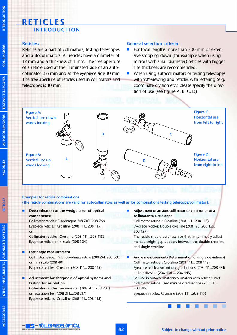
R E T I C L E SR E T I C L E S
AUTOCOLLIM
ATORS
INTRODUCTION
82 Subject to change without prior notice
Reticles:
Reticles are a part of collimators, testing telescopesand autocollimators. All reticles have a diameter of12 mm and a thickness of 1 mm. The free apertureof a reticle used at the illuminated side of an auto-collimator is 6 mm and at the eyepiece side 10 mm.The free aperture of reticles used in collimators andtelescopes is 10 mm.
General selection criteria:� For focal lengths more than 300 mm or exten-
sive stopping down (for example when usingmirrors with small diameter) reticles with biggerline thickness are recommended.
� When using autocollimators or testing telescopeswith 90°-viewing and reticles with lettering (e.g.coordinate division etc.) please specify the direc-tion of use (see figure A, B, C, D)
� Determination of the wedge error of optical
components:
Collimator reticles: Diaphragms 208 740...208 759Eyepiece reticles: Crossline (208 111...208 115)orCollimator reticles: Crossline (208 111...208 118)Eyepiece reticle: mm-scale (208 304)
� Fast angle measurement
Collimator reticles: Polar coordinate reticle (208 241, 208 860)or mm-scale (208 401)Eyepiece reticles: Crossline (208 111... 208 115)
� Adjustment for sharpness of optical systems and
testing for resolution
Collimator reticles: Siemens star (208 201, 208 202)or resolution test (208 211...208 217)Eyepiece reticles: Crossline (208 111...208 115)
� Adjustment of an autocollimator to a mirror or of a
collimator to a telescope
Collimator reticles: Crossline (208 111...208 118)Eyepiece reticles: Double crossline (208 123, 208 125,208 127)The reticle should be chosen so that, in symmetry adjust-ment, a bright gap appears between the double crosslineand single crossline.
� Angle measurement (Determination of angle deviations)
Collimator reticles: Crossline (208 111... 208 118)Eyepiece reticles: Arc minute graduations (208 411...208 431)or line-division (208 436 ... 208 443)For use in autocollimators/collimators with reticle turretCollimator reticles: Arc minute graduations (208 811...208 815)Eyepiece reticles: Crossline (208 111...208 115)
Examples for reticle combinations
(the reticle combinations are valid for autocollimators as well as for combinations testing telescope/collimator):
COLLIM
ATORS
INTRODUCTIO
NTESTIN
GTELE
SCOPES
MODULE
SRETICLE
SALIGNMENTSYSTEMS
OTHERIN
STRUMENTS
ACCESSORIES
Figure A:
Vertical use down-
wards looking
A
B C
D
Figure C:
Horizontal use
from left to right
Figure B:
Vertical use up-
wards looking
Figure D:
Horizontal use
from right to left

AUTOCOLLIM
ATORS
83www.moeller-wedel-optical.com
COLLIM
ATORS
INTRODUCTIO
NTESTIN
GTELE
SCOPES
MODULE
SRETICLE
SALIGNMENTSYSTEMS
OTHERIN
STRUMENTS
ACCESSORIES
CROSSL INE RETICLES
208 123 Double crossline reticle 0,020 0,02
208 125 Double crossline reticle 0,040 0,04
208 127 Double crossline reticle 0,060 0,06
Ord.-No. Description Line spacing
208 502 Tolerance reticle with cross K 90
208 503 Tolerance reticle with coordinate K 90graduation ±2,5°
208 506 Tolerance reticle with coordinate K 90graduation ±2,5°
Ord.-No. Description For instrument
DOUBLE CROSSL INE RETICLES
TOLERANCE RETICLES
208 502
208 503
208 506
208 112208 117208 118
208 111208 113208 115
208 123208 125208 127
208 111 Crossline reticle 0,010 0,010
208 112 Crossline reticle, negative 0,010 0,010
208 113 Crossline reticle 0,020 0,020
208 115 Crossline reticle 0,040 0,040
208 117 Crossline reticle, negative 0,060 0,060
208 118 Crossline reticle, negative 0,35 0,35
Ord.-No. Description Line width

R E T I C L E SR E T I C L E S
AUTOCOLLIM
ATORS
84 Subject to change without prior notice
COLLIM
ATORS
INTRODUCTIO
NTESTIN
GTELE
SCOPES
MODULE
SRETICLE
SALIGNMENTSYSTEMS
OTHERIN
STRUMENTS
ACCESSORIES
208 411 ±60’ ±60’ 2’ 30” AK 90
208 413 ±50’ ±30’ 1’ 15” AK 140
208 415 ±25’ ±15’ 0,5’ 10” AK 200
208 422 ±25’ ±25’ 0,5’ 6” AK 300
208 423 ±12,5’ ±12,5’ 0,25’ 3” AK 500
208 431 ±7’ ±5’ 0,1’ 1” AK 1100
Ord.-No. Total range of graduation Range of fine graduation Smallest interval To be estimated For instrument
208 810 ±60’ ±60’ 2’ 30” AK 90
208 811 ±50’ ±30’ 1’ 15” AK 140
208 812 ±25’ ±15’ 0,5’ 10” AK 200
208 814 ±25’ ±25’ 0,5’ 6” AK 300
208 815 ±12,5’ ±12,5’ 0,25’ 3” AK 500
208 816 ±7’ ±5’ 0,1’ 1” AK 1100
Ord.-No. Total range of graduation Range of fine graduation Smallest interval To be estimated For instrument
RETICLES WITH ANGLE GRADUATION
208 411 208 413 208 415
208 810 208 811 208 812
208 422 208 423 208 431
208 814 208 815 208 816
For use as
eyepiece graduation
For use as
collimator reticle

AUTOCOLLIM
ATORS
85www.moeller-wedel-optical.com
COLLIM
ATORS
INTRODUCTIO
NTESTIN
GTELE
SCOPES
MODULE
SRETICLE
SALIGNMENTSYSTEMS
OTHERIN
STRUMENTS
ACCESSORIES
208 435 ±12¯ ±12¯ 1¯ 0,2¯ AK 200
208 436 ±12¯ ±12¯ 1¯ 0,2¯ AK 200
208 437 ±8¯ ±8¯ 1¯ 0,2¯ AK 300
208 441 ±60¯ ±18¯ 0,5¯ 0,1¯ K, F 90
208 443 ±18¯ ±18¯ 0,5¯ 0,1¯ K, F 300
Ord.-No. Total range of graduation Range of fine graduation Smallest interval To be estimated For instrument
208 740 Diaphragm 0,061 corresponds 30” for AK 140; negative208 741 Diaphragm 0,122 corresponds 1’ for AK 140; negative208 742 Diaphragm 0,244 corresponds 2’ for AK 140; negative208 743 Diaphragm 0,367 corresponds 3’ for AK 140; negative208 744 Diaphragm 0,489 corresponds 4’ for AK 140; negative208 745 Diaphragm 0,611 corresponds 5’ for AK 140; negative208 750 Diaphragm 0,043 corresponds 10” for AK 300; negative208 751 Diaphragm 0,086 corresponds 20” for AK 300; negative208 752 Diaphragm 0,131 corresponds 30” for AK 300; negative208 753 Diaphragm 0,262 corresponds 1’ for AK 300; negative208 754 Diaphragm 0,526 corresponds 2’ for AK 300; negative208 755 Diaphragm 0,790 corresponds 3’ for AK 300; negative208 791 Diaphragm 0,367 corresponds 3’ for AK 140
Ord.-No. Description Remark
RETICLES WITH LINE GRADUATION
DIAPHRAGMS/PINHOLES208 740 208 750208 741 208 751208 742 208 752208 743 208 753208 744 208 754208 745 208 755
208 435 208 436 208 437
208 441 208 443
208 791

R E T I C L E SR E T I C L E S
AUTOCOLLIM
ATORS
86 Subject to change without prior notice
COLLIM
ATORS
INTRODUCTIO
NTESTIN
GTELE
SCOPES
MODULE
SRETICLE
SALIGNMENTSYSTEMS
OTHERIN
STRUMENTS
ACCESSORIES
208 232 Concentric circles 0,168-0,38 Ø 0,168 mm; 0,38 mm, crossline 0,01208 235 Concentric circles 0,5-8 double crossline Ø 0,5; 1; 2; 3; 4; 5; 6; 7; 8 mm; double crossline line space 0,04
208 241 Polar coordinate FK300 2’ to 30’; interval 2’ for K, F 300
208 860 Concentric circles 0,5-8 double crossline as 208 235 but mirror imaged
Ord.-No. Description Remark
208 304 Scale 4-0-4 graduation 0,050 mm from -4 to +4 mm; interval 0,05 mm208 310 Scale 0-10 graduation 0,157 mm corresponds to 6’ for K, F 90208 401 Coordinate graduation 0,100 mm from -4,6 to +4,6 mm; interval 0,10 mm208 850 Scale 4-0-4 graduation 0,050 mm as 208 304, but mirror-imaged208 801 Coordinate graduation 0,100 mm as 208 401, but mirror-imaged
Ord.-No. Description Remark
RETICLES WITH CONCENTR IC C IRCLES
RETICLES WITH SCALES (MM-GRADUATION)
208 304
208 235208 232
208 310 208 401
208 241 208 860
208 801208 850

AUTOCOLLIM
ATORS
87www.moeller-wedel-optical.com
COLLIM
ATORS
INTRODUCTIO
NTESTIN
GTELE
SCOPES
MODULE
SRETICLE
SALIGNMENTSYSTEMS
OTHERIN
STRUMENTS
ACCESSORIES
RESOLUTION TESTS
FOCAULT TESTS
S IEMENS STARS
208 211 208 212
208 213 208 214
208 215 208 217
208 221 208 222
208 201 208 202
208 211 Resolution test 0,0044...0,252corresponds USAF-Test group 2 to 7
208 212 Resolution test 0,0044...0,252 negativecorresponds USAF-Test group 2 to 7
208 213 Resolution test 0,281...1,0 negativecorresponds USAF-Test group 1
208 214 Resolution test 0,562...0,891 negativecorresponds USAF-Test group 0
208 215 Resolution test 0,035...0,5 negativecorresponds USAF-Test group 1 to 4
208 217 Resolution test 0,0086...0,06 with crossline 0,01corresponds USAF-Test group 4 to 6
Ord.-No. Description/Remark
208 201 Siemens star 2x36 sectors208 202 Siemens star 60-sectors with crossline 0,02
Ord.-No. Description/Remark
208 221 Focault test 0,0315...0,1 negative208 222 Focault test 0,016...0,0315 negative
Ord.-No. Description/Remark

A L I G NM ENT S Y S T EM SA L I G NM ENT S Y S T EM S
AUTOCOLLIM
ATORS
INTRODUCTION
88 Subject to change without prior notice
COLLIM
ATORS
INTRODUCTIO
NTESTIN
GTELE
SCOPES
MODULE
SRETICLE
SALIGNMENTSYSTEMS
OTHERIN
STRUMENTS
ACCESSORIES
Alignment systems are precision instruments for thealignment of objects on a reference line, which isdefined by the line of sight of the system. A specialfeature of alignment systems is that the direction ofthe optical axis is conserved during focussing. Thisproperty makes them especially useful for the align-ment of bore holes, bearings, optical set-ups or forthe alignment of guides, axes and planes.Particularly noteworthy on the alignment systems isthe wide setting range of objective distances fromthe tube ending to infinity.The optical axis and focusing lens are concentrical-ly aligned to the barrel with a high degree of pre-cision. Therefore the use of an alignment telescopefor alignment of bore holes, bearings etc. is very sim-ple, as with exact fixing of the alignment telescope
in the reference bore hole or bearing the line of sightis defined already. Depending on measurement taskthree variants are available.An alignment collimator serves to precisely projectan image of the collimator reticle along a line ofreference over varying target distances.Alignment telescopes serve to establish an accurateline of sight to targets at different distances anddetermine the deviation of the targets with respectto the reference line.Alignment autocollimators are a combination of theforegoing variants. They offer the additional possibi-lity of measuring the tilting angle of the target withrespect to the reference line. The eyepiece f=14,7 mmcan be interchanged with eyepieces f=10 mm orf=25 mm to vary the total magnification and the FOV.
LOS Z Z Z ∆s∆s
FF
422
160
Ø4
0f7
FF = Alignment telescopesZ = TargetLOS = Line of sight∆s = Deviation from line of sight
Focussing range: 0 - infinity
Accuracy of line sight: 10 µmThe accuracy of the line of sight denotes the deviation to a
straight line measured in the image plane.Focal length: 80 mm (at 0 m)
to 289 mm (infinity)Free diameter: 26 mm
Technical data
at 0,5 m 5,8x
at 1 m 8,2xat 2 m 12,6x
at 5 m 24x
at 10 m 42x
at 15 m 61x
at 20 m 77x
Magnification of reticle image
ALIGNMENT COLLIMATOR

AUTOCOLLIM
ATORS
89www.moeller-wedel-optical.com
COLLIM
ATORS
INTRODUCTIO
NTESTIN
GTELE
SCOPES
MODULE
SRETICLE
SALIGNMENTSYSTEMS
OTHERIN
STRUMENTS
ACCESSORIES
The upper figure shows the use of an alignmentautocollimator for alignment of bore holes. The tar-gets are positioned into the bore holes and alignedto the line of sight of the alignment telescope.Additionally the targets can serve as a mirror suchthat the bore holes can be adjusted with the align-ment autocollimator parallel to each other.
The MÖLLER-WEDEL OPTICAL alignment systemsare extremely handy. The robust construction withstainless steel tubes guarantees the maintenance ofprecision even in rough environmental conditions.
As manufacturer of optical test equipment MÖL-LER-WEDEL OPTICAL GmbH offers a large range ofaccessories like targets, holders and fixtures, quick ali-gnment tools and mirrors.
Notes on ordering:
Alignment collimator:
� One reticle and LED-illumination are included in thedelivery.
Important: Specify reticle (see page 82) when ordering.
Alignment telescopes:
� Optionally, the telescopes can be equipped with eyepieceshaving 10 mm or 25 mm focal length.
� One reticle is included in the delivery.Important: Specify reticle (see page 82). Specify horizontal orvertical use if reticles with lettering (e.g. coordinate division etc.)are used.
Alignment autocollimator:
� Optionally, the autocollimators can be equipped with eye-pieces having 10 mm or 25 mm focal length.
� Two reticles and LED-illumination are included in thedelivery.
Important: Specify reticles (see page 82). Specify horizontal orvertical use if reticles with lettering (e.g. coordinate division etc.)are used.
LOS Z Z Z
FAK
Description:
An alignment collimator projects a reticle along a line of refe-rence. The real image of the reticle appears 180° rotated.
231 501 FK 300/40
Ord.-No. Description
FAK = Alignment AutocollimatorZ = TargetLOS = Line of sight

A L I G NM ENT S Y S T EM SA L I G NM ENT S Y S T EM S
AUTOCOLLIM
ATORS
ALIGNMENT TELESCOPES
90 Subject to change without prior notice
COLLIM
ATORS
INTRODUCTIO
NTESTIN
GTELE
SCOPES
MODULE
SRETICLE
SALIGNMENTSYSTEMS
OTHERIN
STRUMENTS
ACCESSORIES
Description:
An alignment telescope with straight viewing has the user’s lineof sight co-linear with the objective axis. The image of the targetappears in the eyepiece focal plane laterally and vertically rever-ted. These alignment telescopes are preferably used in horizontaldirection, where the eyepiece is at eye level.
231 701 FFG 300/40/14,7
Ord.-No. Description
375
160
Ø4
0f7
WITH STRAIGHT VIEWING
375
160
13
8
Ø4
0f7
WITH STRAIGHT VIEWING AND DIGITAL DOUBLE MICROMETER
Description:
An alignment telescope with 90°-viewing has the user’s line ofsight at 90° to the objective axis. By a special deflection optic thetarget image appears in the eyepiece focal plane upright andright-way round.These alignment telescopes are preferably used down-lookingor on optical tables where a straight viewing is not feasible.
336
160
Ø4
0f7
69
WITH 90°-VIEWING
Description:
The alignment telescope with digital double micrometer enablesto measure the target image displacement in the eyepiece imageplane. If the target distance is known, the target displacementcan be calculated.
231 702 FFR 300/40/14,7
Ord.-No. Description
231 711 FFG 300/40/14,7 MDD
Ord.-No. Description
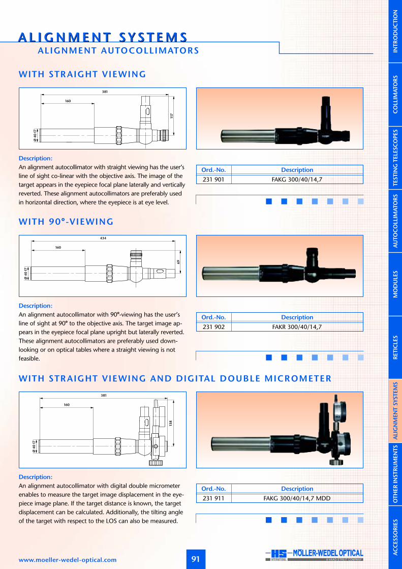
AUTOCOLLIM
ATORS
A L I G NM ENT S Y S T EM SA L I G NM ENT S Y S T EM SALIGNMENT AUTOCOLLIMATORS
91www.moeller-wedel-optical.com
COLLIM
ATORS
INTRODUCTIO
NTESTIN
GTELE
SCOPES
MODULE
SRETICLE
SALIGNMENTSYSTEMS
OTHERIN
STRUMENTS
ACCESSORIES
Description:
An alignment autocollimator with straight viewing has the user’sline of sight co-linear with the objective axis. The image of thetarget appears in the eyepiece focal plane laterally and verticallyreverted. These alignment autocollimators are preferably usedin horizontal direction, where the eyepiece is at eye level.
231 901 FAKG 300/40/14,7
Ord.-No. Description
381
160
117
Ø4
0f7
WITH STRAIGHT VIEWING
Ø4
0f7
13
8
381
160
WITH STRAIGHT VIEWING AND DIGITAL DOUBLE MICROMETER
Description:
An alignment autocollimator with 90°-viewing has the user’sline of sight at 90° to the objective axis. The target image ap-pears in the eyepiece focal plane upright but laterally reverted.These alignment autocollimators are preferably used down-looking or on optical tables where a straight viewing is notfeasible.
Ø4
0f7
69
434
160
WITH 90°-VIEWING
Description:
An alignment autocollimator with digital double micrometerenables to measure the target image displacement in the eye-piece image plane. If the target distance is known, the targetdisplacement can be calculated. Additionally, the tilting angleof the target with respect to the LOS can also be measured.
231 911 FAKG 300/40/14,7 MDD
Ord.-No. Description
231 902 FAKR 300/40/14,7
Ord.-No. Description

AUTOCOLLIM
ATORS
92 Subject to change without prior notice
COLLIM
ATORS
INTRODUCTIO
NTESTIN
GTELE
SCOPES
MODULE
SRETICLE
SALIGNMENTSYSTEMS
OTHERIN
STRUMENTS
ACCESSORIES
10 10 80...100
Ø3
7
Ø4
2
M2
4x0
,75
DYNAMETER
Description:
Diopter telescopes are adjustable focus telescopes that serve themeasurement of optical power of lenses in diopter. The measu-ring result can be directly read from the diopter graduation.
Application examples:
� Fast testing of optical power� Testing the diopter graduation and infinity adjustment of
eyepieces� For additional enlargement on telescopes, e.g. when
adjusting reticles� As Reading Telescope in the negative distance range
163
Ø3
8
¨4
2
L
Ø4
2
¨4
5
DIOPTER TELESCOPES
Description:
� For measurement of telescope magnification� For diameter measurement of the exit pupil� For measurement of the distance between exit pupil and
eyepiece� Lens magnification 7,5x
233 241 Dynameter233 245 Tube attachment 10 mm
Ord.-No. Description
OTH E R I N S T R UM ENT SOTH E R I N S T R UM ENT SINSTRUMENTS FOR THE OPTICAL WORKSHOP
Besides the modular designed testing telescopes andcollimators MÖLLER-WEDEL OPTICAL offers a wholelot of other telescopes and collimators for diversemeasuring tasks in the optical workshop.
For alterations of the magnification interchangeableeyepiece f=10 mm and f=25 mm can be used as anoption.
233 202 Diopter telescope ±1,5 +1,5 to –1,5 dpt 0,25 dpt 6° 90 mm – A233 212 Diopter telescope +6,0/–3,0 +6,0 to –3,0 dpt 0,20 dpt 11° 50 mm 79...99 B
233 222 Diopter telescope +0,2/–5,8 +0,2 to –5,8 dpt 0,20 dpt 11° 50 mm 90...110 B
233 234 Diopter telescope ±5,0 +5,0 to –5,0 dpt 0,10 dpt 13° 40 mm 76...93 B
Ident.-Nr. Description Meas. range Scale division Field of view at ∞ Focal length L Fig.
Fig. A
Fig. B

AUTOCOLLIM
ATORS
93www.moeller-wedel-optical.com
COLLIM
ATORS
INTRODUCTIO
NTESTIN
GTELE
SCOPES
MODULE
SRETICLE
SALIGNMENTSYSTEMS
OTHERIN
STRUMENTS
ACCESSORIES
Description:
� For the magnified representation of remote objects� Reticle 208 111 (crossline 10 µm)� Tube diameter Ø 25 mm� Focal length objective f=50 mm
The telescopes magnification can be calculated at the infinitysettings as follow:f1 – Focal length of the objectivef2 – Focal length of the eyepiece
L1
Ø2
5
Ø3
4
L2
READING TELESCOPES WITH FOCUS ING ADJUSTMENT
12
255
142
¨ 40
12
208
142
¨ 40
SQUARE BODY TELESCOPES AND COLLIMATORS
233 252 Reading telescope D25 U/105 from ∞ 3,4 x 11,5° 100 mm 50 mmto 105 mm 12,0 x 14,0 mm 136 mm
233 255 Reading telescope D25 213/73 from 213 mm 4,7 x 36,0 mm 117 mm 67 mmto 73 mm 23,0 x 7,5 mm 169 mm
233 258 Reading telescope D25 97/51 from 97 mm 14 x 12,5 mm 141 mm 91 mmto 51 mm 52 x 3,3 mm 210 mm
Ord.-No. Description Object distance Reading magnification Field of view L1 L2
Description:
� For use on plane reference surfaces� Measurement for 180°-reversion
Square body with ground surface� Parallelism of optical to mechanical axes: < 10”� Eyepiece and illumination are freely interchangeable
� Telescope magnification 9,5 x� Focal length objective 140 mm� Field of View (with eyepiece f=14,7 mm) 4,0°
� Free aperture objective 16 mm
233 101 FQ 140/40 f= 14,7 – 208 125 Double crossline 0,04
233 103 KQ 140/40 – 6V/5W 208 111 Single crossline 0,01
Ord.-No. Description Eyepiece Illuminator Reticle
V = f1 / f2

ACC E S SO R I E SACC E S SO R I E S
AUTOCOLLIM
ATORS
F IXTURES
94 Subject to change without prior notice
COLLIM
ATORS
INTRODUCTIO
NTESTIN
GTELE
SCOPES
MODULE
SRETICLE
SALIGNMENTSYSTEMS
OTHERIN
STRUMENTS
ACCESSORIES
100
82
46 78
40
Ø40
H8
M6 x 8DIN 913
60
Ø 7
60
75
CLAMP F IXTURE D40/ONE-S IDED
100
60
25 25
60
101
82 M6 x 6DIN 913
75
Ø 7
60
Ø40
H8
CLAMP F IXTURE D40/DOUBLE-S IDED
170
95
112
140
32 32
114
60
M8 x 12DIN 913
110
Ø 9
Ø65
H8
CLAMP F IXTURE D65/DOUBLE-S IDED
223 002 Clamp fixture D40/one-sided
Ord.-No. Description
223 008 Clamp fixture D40/double-sided
Ord.-No. Description
223 003 Clamp fixture D65/double-sided
Ord.-No. Description

AUTOCOLLIM
ATORS
95www.moeller-wedel-optical.com
COLLIM
ATORS
INTRODUCTIO
NTESTIN
GTELE
SCOPES
MODULE
SRETICLE
SALIGNMENTSYSTEMS
OTHERIN
STRUMENTS
ACCESSORIES
80
115
60
Ø 9
140
Ø10
5
110
CLAMP F IXTURE D105
M6 x 16 DIN 912
62
M6 x 16 DIN 913
45
100 0,2
10
00
,2
Ø65
H8
Ø 65 Ø40
CLAMP F IXTURE-SET
M8
190
180
74
258M6
158
16
0
Ø128
CLAMP F IXTURE D128
223 005 Clamp fixture D105
Ord.-No. Description
223 038 Clamp fixture D128
Ord.-No. Description
223 035 Clamp fixture D40 (223 037 + 223 035 01)
223 037 Clamp fixture D65
223 035 01 Adapter D40
Ord.-No. Description

ACC E S SO R I E SACC E S SO R I E S
AUTOCOLLIM
ATORS
F IXTURES
96 Subject to change without prior notice
COLLIM
ATORS
INTRODUCTIO
NTESTIN
GTELE
SCOPES
MODULE
SRETICLE
SALIGNMENTSYSTEMS
OTHERIN
STRUMENTS
ACCESSORIES
125
20
M6 deep5
Ø 6,4
166
110
10
05
0
Ø65 H8
ADJUSTABLE HOLDERS
12
5
250
270
18
6
13
2
15
0
Ø 65 H8
TR IPOD FOR
ADJUSTABLE HOLDERS
223 080 Tripod for 223 023/024
223 082 Tripod for 223 056
Ord.-No. Description
223 056 Adjustable holder D65
223 035 01 Adapter D40
Ord.-No. Description
223 023 Adjustable holder D40
223 024 Adjustable holder D65
Ord.-No. DescriptionAdjustable ±4°in both axes
Adjustable ±2°in both axes

AUTOCOLLIM
ATORS
97www.moeller-wedel-optical.com
COLLIM
ATORS
INTRODUCTIO
NTESTIN
GTELE
SCOPES
MODULE
SRETICLE
SALIGNMENTSYSTEMS
OTHERIN
STRUMENTS
ACCESSORIES
V-PR ISM
VERTICAL STANDS FOR AUTOCOLLIMATORS MODULAR SYSTEM
70
102,5
9599
116
Ø 65
Ø 40
223 007 Magnetic prism
Ord.-No. Description
Components
Column D40
Adjust. height stand D65
Mount D40
Mount D65
Pedestal
Tilting joint
Base plate
Adapter plate
Tiltable table
X-Y-translation table
Models
Vertical stand D40
with tiltable tableOrd.-No. 223 091
Vertical stand D65
with tiltable tableOrd.-No. 223 092
Tiltable stand D40
with tiltable tableOrd.-No. 223 093
Tiltable stand D65
with tiltable tableOrd.-No. 223 094
Adjust. height stand D40
with tiltable tableOrd.-No. 223 095
Adjust. height stand D65
with tiltable tableOrd.-No. 223 096
Adjust. height stand D40
with X-Y tableOrd.-No. 223 097
Adjust. height stand D65
with X-Y tableOrd.-No. 223 098
� � � � � �
� � � � � �
� � � � � �
� � � � � �
� � � � � �
� � � � � �
� � � � � �
� � � � � �
Column D40
Mount
D40
Mount
D65
Tilting joint
Tiltabe table
X-Y-translation
table
Base plate Adapter plate
Pedestal
Adjustable
height stand

ACC E S SO R I E SACC E S SO R I E S
AUTOCOLLIM
ATORS
ALIGNMENT AIDS
98 Subject to change without prior notice
COLLIM
ATORS
INTRODUCTIO
NTESTIN
GTELE
SCOPES
MODULE
SRETICLE
SALIGNMENTSYSTEMS
OTHERIN
STRUMENTS
ACCESSORIES
74
64
Ø40
LASER ATTACHMENT D40
Ø65
74
64
LASER ATTACHMENT D65
Spiegel
mirror
Ø 34
46
30
AC-F INDER PR ISM
219 760 Laser attachment D40 with power supply
219 750 Laser attachment D65 with power supply
Ord.-No. Description
221 031 AK-finder prism
Ord.-No. Description
Description:
The laser attachments D40 and D65 are useful for fast coarsealignment of autocollimators. They are especially handy for alig-ning distant or very small mirrors, polygons and prisms.
Description:
Das AC-finder prism is designed for alignment of mirrors withrespect to autocollimators at short distances.

AUTOCOLLIM
ATORS
ACC E S SO R I E SACC E S SO R I E SACCESSOR IES FOR OBJECTIVE TUBES
99www.moeller-wedel-optical.com
COLLIM
ATORS
INTRODUCTIO
NTESTIN
GTELE
SCOPES
MODULE
SRETICLE
SALIGNMENTSYSTEMS
OTHERIN
STRUMENTS
ACCESSORIES
M36 x 0,75
70
30
0,001
6
SUPPORTING FLANGE D40
0,001
M60 x 1
90
52
10
SUPPORTING FLANGE D65
M D
L
ACHROMAT ATTACHMENTS IN MOUNT
221 001 Supporting flange D40
221 003 Supporting flange D65
Ord.-No. Description
Description:
Supporting flanges of type D40 and D65 are factory alignedperpendicular to the optical axis. They are screwed in front ofthe objective tubes. Alignment will be lost by unscrewing.
221 048 VA f=50/12 D40 M36x0,75 11,0 39,5
221 051 VA f=90/16 D40 M36x0,75 13,5 39,5
221 053 VA f=140/28 D40 M36x0,75 29,5 39,5
221 055 VA f=200/28 D40 M36x0,75 29,5 39,5
221 059 VA f=300/28 D40 M36x0,75 29,5 39,5
221 063 VA f=500/28 D40 M36x0,75 29,5 39,5
221 067 VA f=800/28 D40 M36x0,75 21,5 39,5
221 057 VA f=200/50 D65 M60x1 28,5 64,0
221 061 VA f=300/50 D65 M60x1 28,5 64,0
221 065 VA f=500/50 D65 M60x1 28,5 64,0
Ord.-No. Description M L D

ACC E S SO R I E SACC E S SO R I E S
AUTOCOLLIM
ATORS
MIRRORS
100 Subject to change without prior notice
COLLIM
ATORS
INTRODUCTIO
NTESTIN
GTELE
SCOPES
MODULE
SRETICLE
SALIGNMENTSYSTEMS
OTHERIN
STRUMENTS
ACCESSORIES
166
125 x 50
Ø 6,4/Ø 11
110
10
5
Ø96
MIRROR D100
55
27,5
Ø 4
M6
55
Ø60
25
32
KM4-DIN 74
(4x)
¨ 60
Ø10
5
Ø10
0 Ø63
Ø60
frei
MIRROR IN MOUNT
223 221 Mirror D100/adjustable, double sided, 2”
Ord.-No. Description
223 210 Mirror D63/adjustable, permanent magnetic clamp
Ord.-No. Description
223 260 Mirror in mount/one-sided223 262 Mirror in mount/double-sided, 2”
Ord.-No. Description

AUTOCOLLIM
ATORS
101www.moeller-wedel-optical.com
COLLIM
ATORS
INTRODUCTIO
NTESTIN
GTELE
SCOPES
MODULE
SRETICLE
SALIGNMENTSYSTEMS
OTHERIN
STRUMENTS
ACCESSORIES
55
55
25
45
19
2,5
Ø 4 m6 M6
M6
100 0,2
50 0,2
BASE 100
100 0,2
50 0,2
R50
1
STOP BAR FOR BASE 100
10
0
MAGNETIC BASE FOR MIRROR
223 282 Magnetic base for mirror 223 260/223 262
Ord.-No. Description
223 264 Base 100/50
223 269 Stop bar for base 100/50
Ord.-No. Description

ACC E S SO R I E SACC E S SO R I E S
AUTOCOLLIM
ATORS
AUTOCOLLIMATOR-TEST-WEDGE AND PENTAPR IMS
102 Subject to change without prior notice
COLLIM
ATORS
INTRODUCTIO
NTESTIN
GTELE
SCOPES
MODULE
SRETICLE
SALIGNMENTSYSTEMS
OTHERIN
STRUMENTS
ACCESSORIES
149
80
50
10
010
0
10
0
Km6-DIN74
AUTOCOLLIMATOR-TEST-WEDGE
M32 x 0,75
45
65
29,5
M3
2x
0,7
5
83
55
Ø 40
frei
PENTAPR ISMS (OPTICAL SQUARES)
223 244 Autocollimator-Test-Wedge
Ord.-No. Description
221 015 Pentaprism 2” in mount221 018 Pentaprism 5” in mount221 016 Pentaprism 2” with wedge in mount221 019 Pentaprism 5” with wedge in mount
Ord.-No. Description
Description:
The certificated Autocollimator-Test-wedge is used as quickreference for on site testing of visual and electronic autocolli-mators.

AUTOCOLLIM
ATORS
103www.moeller-wedel-optical.com
COLLIM
ATORS
INTRODUCTIO
NTESTIN
GTELE
SCOPES
MODULE
SRETICLE
SALIGNMENTSYSTEMS
OTHERIN
STRUMENTS
ACCESSORIES
M32 x 0,75
100
120
55
92
94
BASE FOR PENTAPR ISM
99 76
99
M32 x 0,75
M6
0x
1,0
HOLDER FOR PENTAPR ISM
221 027 Base for pentaprism
Ord.-No. Description
221 023 Holder D65 for pentaprism
Ord.-No. Description

AUTOCOLLIM
ATORS
104 Subject to change without prior notice
COLLIM
ATORS
INTRODUCTIO
NTESTIN
GTELE
SCOPES
MODULE
SRETICLE
SALIGNMENTSYSTEMS
OTHERIN
STRUMENTS
ACCESSORIES
45
45
90o 45
180o
45
90o
PENTAPR ISMS
Ø 16
Ø 38
37,
5
Ø 135
POLYGON MIRROR 8 FACES
Ø3
0
Ø 115
Ø 25
Ø 16
POLYGON MIRROR 12 FACES
205 307 Polygon mirror 8 faces 2”
Ord.-No. Description
205 313 Polygon mirror 12 faces 2”
Ord.-No. Description
ACC E S SO R I E SACC E S SO R I E SPOLYGON MIRRORS AND PENTAPR ISMS
205 331 Pentaprism 2”
205 332 Pentaprism 5”
Ord.-No. Description
221 017 Pentaprism 2” with wedge 2”
221 020 Pentaprism 2” with wedge 5”
Ord.-No. Description
Thickness 45 mm Thickness 45 mm

AUTOCOLLIM
ATORS
105www.moeller-wedel-optical.com
COLLIM
ATORS
INTRODUCTIO
NTESTIN
GTELE
SCOPES
MODULE
SRETICLE
SALIGNMENTSYSTEMS
OTHERIN
STRUMENTS
ACCESSORIES
50
30
120o
52
52 90
o
REFLECTING PR ISM 120° REFLECTING PR ISM 90°
ACC E S SO R I E SACC E S SO R I E SREFLECTING PR ISMS
205 363 Reflecting prism 120° ±1”
205 364 Reflecting prism 120° ±4”
Ord.-No. Description
205 360 Reflecting prism 90° ±1”
205 361 Reflecting prism 90° ±4”
Ord.-No. Description
55
65
60o
52
52
45o
REFLECTING PR ISM 60° REFLECTING PR ISM 45°
52
35
30o
REFLECTING PR ISM 30°
205 357 Reflecting prism 60° ±1”
205 358 Reflecting prism 60° ±4”
Ord.-No. Description
205 354 Reflecting prism 45° ±1”
205 355 Reflecting prism 45° ±4”
Ord.-No. Description
205 351 Reflecting prism 30° ±1”
205 352 Reflecting prism 30° ±4”
Ord.-No. Description
Thickness 50 mm
Thickness 50 mm Thickness 50 mm
Thickness 50 mm Thickness 50 mm

AUTOCOLLIM
ATORS
106 Subject to change without prior notice
COLLIM
ATORS
INTRODUCTIO
NTESTIN
GTELE
SCOPES
MODULE
SRETICLE
SALIGNMENTSYSTEMS
OTHERIN
STRUMENTS
ACCESSORIES
ACC E S SO R I E SACC E S SO R I E STV-SET
For use along with testing telescopes and autocollimators,consisting of:
� Camera-Adapter C-Mountfor attachment of a CCD-camera with C-Mount to theeyepiece f=14,7 mm or f=25 mm with integrated optics forimaging on the CCD-chip plane
� 1/2” inch CCD-camera,monochromatic, 768x576 pixel
� BNC-cablefor connecting the camera to the TV-monitor
� TV-Monitormonochrome, CCIR-standards
� Power supply CCD-camera
The C-Mount Camera-Adapter (Id.-Nr. 133 401 07) can beordered separately.
TV-SET
229 920 TV-Set
Ord.-No. Description
COMEF_ANGLE is an image processing system, that serves thecomputer-aided evaluation of angle measurements and angleadjustments performed with autocollimators or with combinationcollimator-testing telescope.It serves to objectify, automate and increase the precision ofangle measurements and allows measurements to be recorded.
In combination with autocollimators or collimator-telescopes,retrofitted with a CCD-camera, the following measuring taskscan be solved:
� Deflection angle measurement of optical flats, filters andprisms
� Wedge angle measurement/ parallelism measurement ofoptical flats
� Prism angle measurement (relative measurement against amaster prism)
� Alignment of optical flats, mirrors, prisms� Measurement of centering error
SOFTWARE COMEF_ANGLE
219 770 Image processing system for visual autocolli-mators, collimator-telescope combinationconsisting of:� Software COMEF_ANGLE� Frame grabber� Cable� Operation manual
Additional required:Pentium PC with WINDOWS® operation system
Ord.-No. Description

AUTOKOLLIMATOREN
107www.m
oeller-w
edel-o
ptical.co
m
KOLLIMATOREN EINFÜHRUNGPRÜFFERNROHREBAUGRUPPENSTRICHPLATTENFLUCHTUNGSSYSTEMEANDERE GERÄTEZUBEHÖR
NOTES
NOTES
MÖLLER-W
EDELOPTIC
AL