Embed Size (px)
Citation preview

1
m!kabriefing
book
2 3
Thank you for choosing Yellowtec products.
Enjoy m!ka, the most exciting support system for microphones and monitors. m!ka is robust, sleek and flexible.
All components are designed to fit with each other and can be combined in multiple ways. Check this Briefing Book to get initial information on how to install and adjust the system.
Please note: Safety instructions should be followed at all times!
Briefing Book Content
m!ka Mic Armm!ka Studio Light
MMS PDM KitMMS Power Sting
MMS Ceiling MountMMS Wall Mount
MMS Monitor Mountm!ka QuickFix
MMS Cable ClampMMS Safety Stop
m!ka Monitor Armm!ka Bushing
m!ka Pole Adapterm!ka Table Clamp
m!ka Table Through Mount m!ka Table Top Mount
MMS Wall BracketMMS System Wall
m!ka PadDockm!ka Copy Stand
Remarks
48 12131415161820212223242526272829303234
4 5
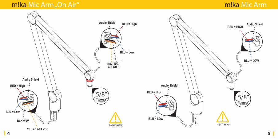
m!ka Mic Arm „On Air“
RED = High
RED = High
Audio Shield
Audio Shield
BLU = Low
BLU = Low
Cut Off !N/C N/C
BLK = 0V
YEL = 12-24 VDC
5/8“
Remarks
RED = HIGH
RED = HIGH
Audio Shield
Audio Shield
BLU = LOW
BLU = LOW
m!ka Mic Arm
5/8“
Remarks
6 7
Remarks
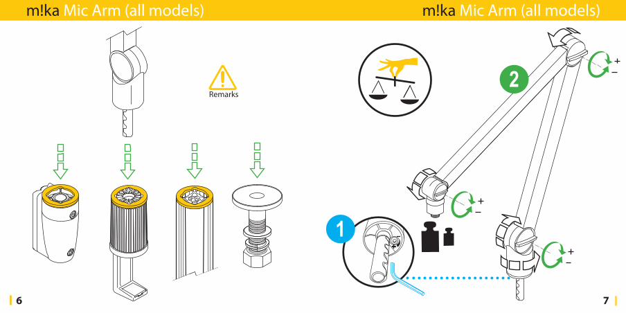
m!ka Mic Arm (all models)m!ka Mic Arm (all models)
8 9
Remarks
Remarks
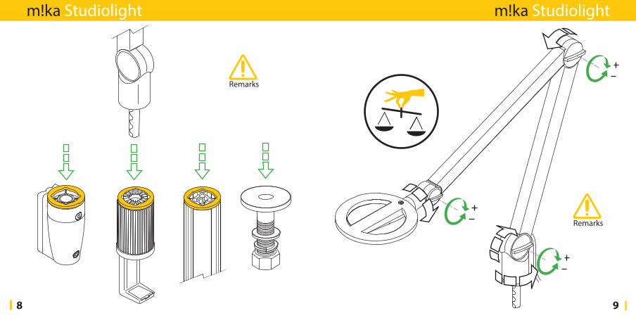
m!ka Studiolight m!ka Studiolight
10 11
1.
2.
Remarks
Remarks
m!ka Studiolight m!ka Studiolight
12 13
Remarks Remarks
m!ka MMS PDMKit m!ka Power Sting
14 15
Remarks Remarks
m!ka MMS Ceiling Mount m!ka Wall Mount
16 17
3
4 Remarks
Remarks
m!ka MMS Monitor Mount m!ka MMS Monitor Mount
18 19
Remarks
m!ka MMS QuickFix m!ka MMS QuickFix
20 21
Remarks
STOP
Remarks
m!ka MMS Cable Clamp m!ka MMS Safety Stop
22 23
Remarks Remarks
22 mm
m!ka MMS Monitor Arm (Friction) m!ka Bushing
24 25
3 Remarks
m!ka MMS Pole Adapter m!ka Table Clamp
26 27
Remarks
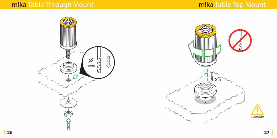
m!ka Table Through Mount m!ka Table Top Mount
28 29
Remarks
3
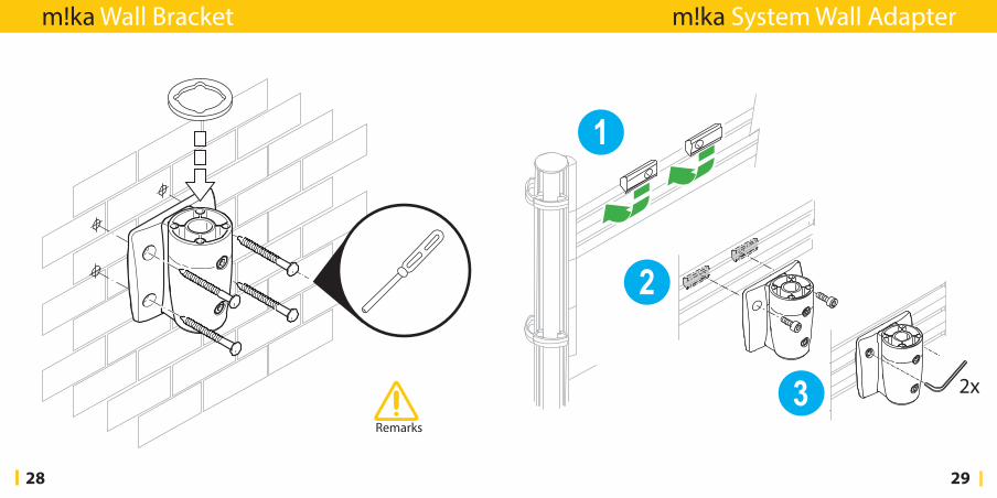
m!ka Wall Bracket m!ka System Wall Adapter
30 31
Remarks
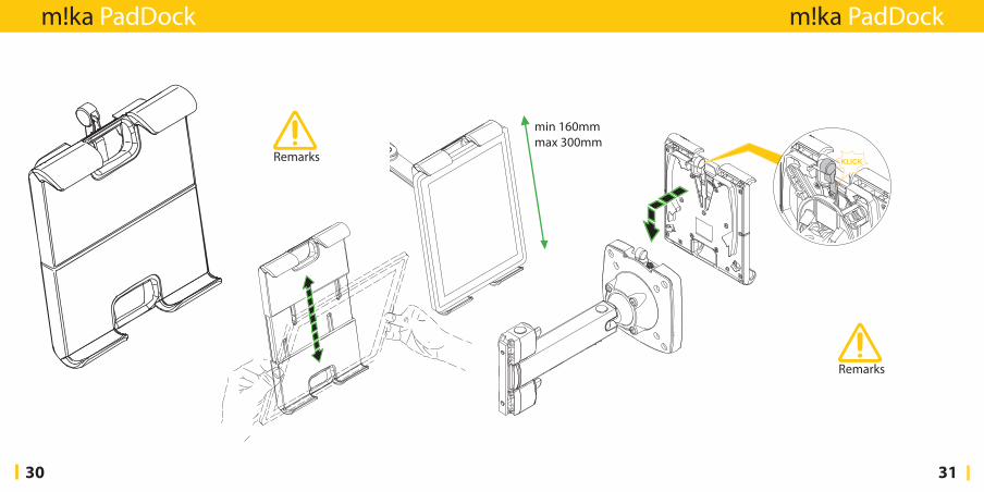
min 160mmmax 300mm
Remarks
m!ka PadDock m!ka PadDock
32 33
Remarks
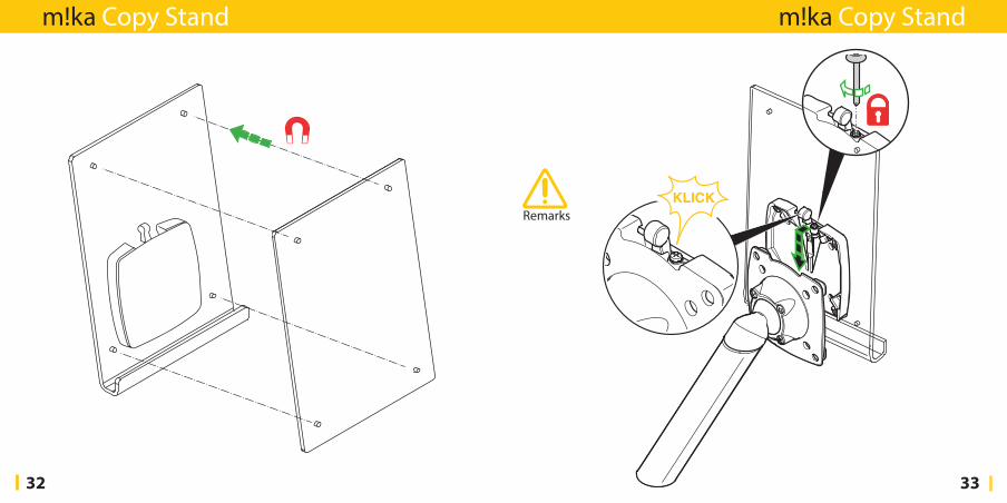
m!ka Copy Stand m!ka Copy Stand
34 35
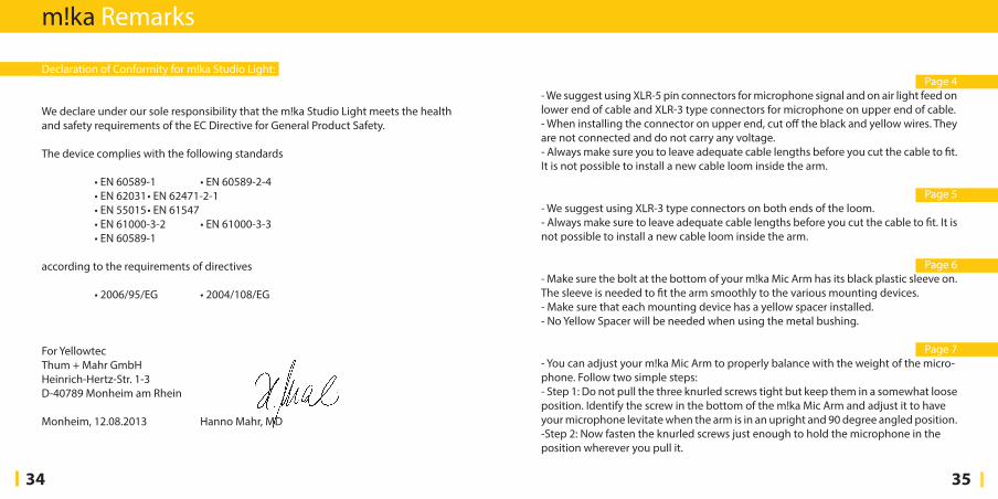
Declaration of Conformity for m!ka Studio Light:
We declare under our sole responsibility that the m!ka Studio Light meets the health and safety requirements of the EC Directive for General Product Safety.
The device complies with the following standards
•EN60589-1 •EN60589-2-4 •EN62031•EN62471-2-1 •EN55015•EN61547 •EN61000-3-2 •EN61000-3-3 •EN60589-1
according to the requirements of directives
•2006/95/EG •2004/108/EG
For YellowtecThum + Mahr GmbHHeinrichHertzStr. 13D40789 Monheim am Rhein
Monheim, 12.08.2013 Hanno Mahr, MD
Page 4 We suggest using XLR5 pin connectors for microphone signal and on air light feed on lower end of cable and XLR3 type connectors for microphone on upper end of cable. When installing the connector on upper end, cut off the black and yellow wires. They are not connected and do not carry any voltage. Always make sure you to leave adequate cable lengths before you cut the cable to fit. It is not possible to install a new cable loom inside the arm.
Page 5 We suggest using XLR3 type connectors on both ends of the loom. Always make sure to leave adequate cable lengths before you cut the cable to fit. It is not possible to install a new cable loom inside the arm.
Page 6 Make sure the bolt at the bottom of your m!ka Mic Arm has its black plastic sleeve on. The sleeve is needed to fit the arm smoothly to the various mounting devices. Make sure that each mounting device has a yellow spacer installed.-NoYellowSpacerwillbeneededwhenusingthemetalbushing.
Page 7 You can adjust your m!ka Mic Arm to properly balance with the weight of the microphone. Follow two simple steps: Step 1: Do not pull the three knurled screws tight but keep them in a somewhat loose position. Identify the screw in the bottom of the m!ka Mic Arm and adjust it to have your microphone levitate when the arm is in an upright and 90 degree angled position. -Step2:Nowfastentheknurledscrewsjustenoughtoholdthemicrophoneintheposition wherever you pull it.
m!ka Remarks
36 37
Do not pull the knurled screws too tight. They may break and the joints may squeak. Instead readjust the screw inside the bottom as in Step 1. If necessary, use Teflon spray in case of joint squeak.
Page 8 Make sure the bolt at the bottom of your m!ka Studio Light has its black plastic sleeve on. The sleeve is needed to fit smoothly to the various mounting devices. Make sure that the mounting device has a yellow spacer installed.-NoYellowSpacerwillbeneededwhenusingthemetalbushing.
Page 9 Your m!ka Studo Light is prebalanced. Do not pull the knurled screws too tight. They may break and the joints may squeak. In case, use Teflon spray in case of joint squeak.
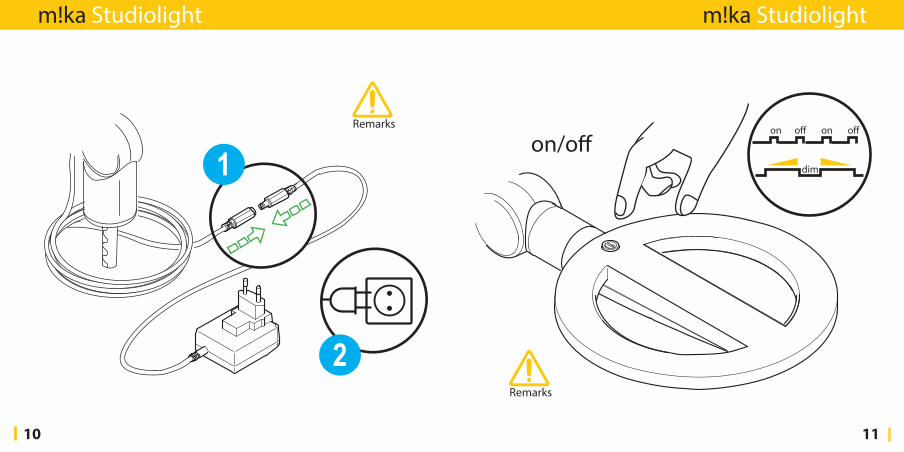
Page 10Pay attention when connecting your m!ka Studio Light to mains voltage! Step 1: Always connect the low voltage connector prior to connecting to the mains. Step 2: Select the correct mains adapter for your country and clip it to the wall PSU.
Page 11Your m!ka Studio Light has an integrated DIM function.-PressshortforswitchingON/OFF. Press long to DIM up, press long again to DIM down. m!ka Studio Light will remember the last DIM value when switching it on again.
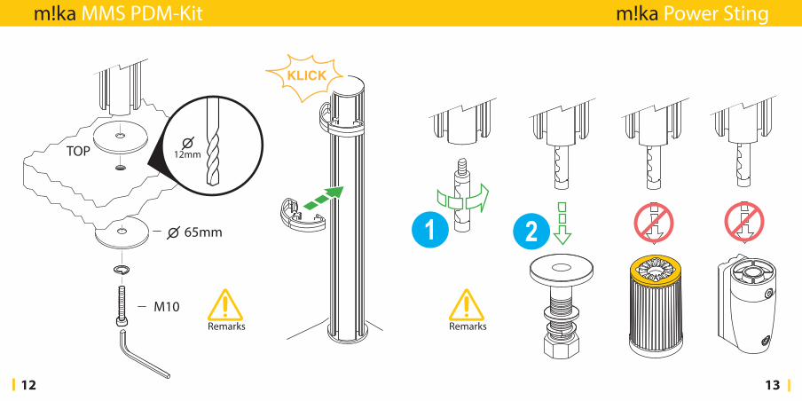
Page 12 To secure proper upright mounting of the MMS pole we suggest drilling a minimum
hole of 12mm diameter for the PDM Kit. If you need to use your own threaded bolt make sure you use M10 metric thread. The cable organizer clip will help to tidy your wiring.
Page 13-NeverusethePowerStingotherthanwiththeoriginalm!kaBushing.Tableclampsare not suitable to hold an MMS arm. Use a gripper to fix the Power Sting.
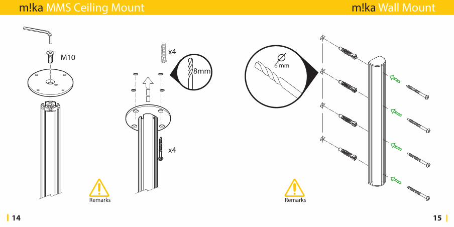
Page 14 When installing the m!ka Ceiling Mount it is your obligation to verify that your ceiling and your fasteners are suitable to hold the load.
Page 15 When installing the m!ka Wall Mount it is your obligation to verify that your wall and your fasteners are suitable to hold the load.
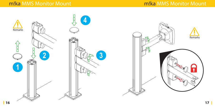
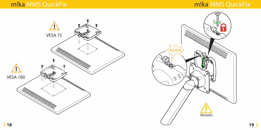
Page 16 Make sure you have checked the max. payload of your m!ka Monitor Arm. The information is printed on the product label on the rearside of the QuickFix. See Page 21 for how to secure a minimum headroom under your monitor.
Page 17 In order to prevent unintended changes to the MMS height position simply remove the thumbscrews by pulling them out. Before you remove the screws make sure they are all properly tightend.
Page 18 The MMS QuickFix adapter is suitable to be used with VESA 75 and VESA 100 fixtures.
m!ka Remarks
38 39
Make sure that you use the correct screw size and length. Too long screws will damage your flat panel!
Page 19 You can deactivate the QuickFix function for security reasons. Turn in the screw next to the release lever in order to disengage its function.
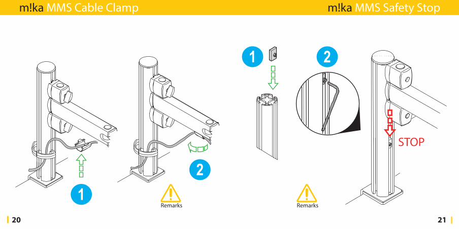
Page 20 Insert the cable organizer clips into the bottom profile of the MMS Arm and turn it 90° to fix it.
Page 21 To secure a minimum vertical position of your monitor insert the MMS Safety Stop NutintotheMMSpole.UseanAllenkeyandfastenitproperly.
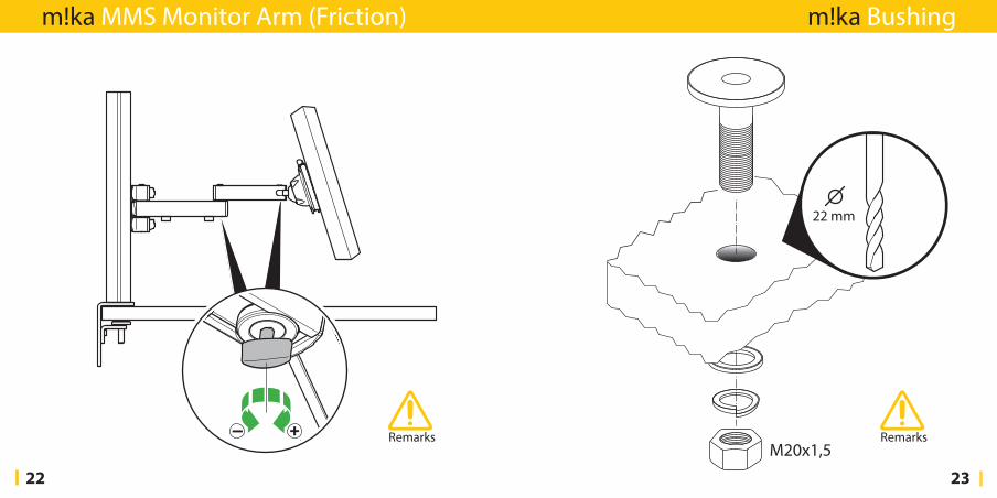
Page 22 Use the Allen key of the thumbscrew for the height adjustment to de or increase the friction of the joints of your m!ka Monitor Arm
Page 23 To secure proper upright positioning of the m!ka Bushing drill a hole with a mimum diameter of 22 mm. The thread of the bushing is metric; should you ever need to replace the nut make sure you use the correct M20x1,5 thread.
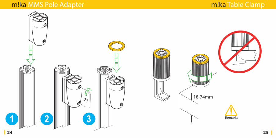
Page 24 Use an Allen key to fix the MMS Pole Adapter properly. Use a Yellow Spacer with the MMS Pole Adapter.
Page 25-Neverusethem!kaTableClamponcurvedsurfaces-itmayslipoff!
Page 27 You do not need to drill a central hole when you use a m!ka Table Top Mount. Make sure you have suitable screws for the type of panel you install the base ring to.
Page 28 When installing the m!ka Wall Bracket it is your obligation to verify that your wall and your fasteners are suitable to hold the load. Use a Yellow Spacer.
Page 30 Make sure the m!ka Pad Dock is properly oriented to support the tablet. In order to hold the tablet properly its size needs to be min 160mm and max 300mm. Tablets will fit at both landscape and upright orientation.
Page 32 The cover pane for your m!ka Copy Stand holds and aligns by the integrated magnets. Make sure the magnets face each other.
Page 33 Your m!ka Copy Stand adapts to the MMS QuickFix system. Slide it in until it locks with a klick. You can deactivate the QuickFix function for security reasons. Turn in the screw next to the release lever in order to disengage its function.
m!ka Remarks

40
yellowtec.com
m!kaBBV3.1