Embed Size (px)
Citation preview
MJP engineering
Valve Lift Designer Instructions.
This program uses Splines to generate the lift curve, with this approach it is fairly easy to copy any measured Cam lift
curve and then modify it.
Splines aren’t as limited as the more common Polynomial curve approach and with Splines it’s easy to design an
asymmetric lift profile. With the adjustable 2 stage smoothing function it’s also easy to get low Jerk values without
compromising the lift curve.
The left picture shows an unsmoothed curve and the right one uses 5 primary and 50 in secondary smoothing.
If a lift curve is smoothed more than necessary it will compromise engine performance, particularly because of the less
aggressive lift curve transition from Ramp to Flank the smoothing produces.
The Program works in Valve lifts and Camshaft degrees.
This means that lift measurements taken directly of a Cam as it normally would be, have to be multiplied by the
Rocker arm ratio (multiplier available in the Cam Explorer and the 3 Comparison Cams) before further work is done.
Exceptions are the “Duration Calc” and the “Cam report” pages.
On these pages the Camshaft degrees are converted to Crankshaft degrees.
.
The colors on the design Page are:
Red: Lift curve.
Green: Velocity, 1st
derivative.
Blue: Acceleration, 2nd
derivative.
Orange: Jerk, 3rd
derivative.
Start Page.
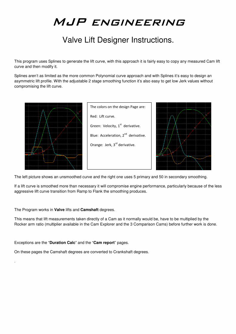
The opening Page sets up the measurement units, loads / saves Cam designs and have a lift curve wizard.
The curve wizard can either be used for generating a new lobe from scratch, or for approximating a curve to best fit a
measured cam lobe before doing the fine adjustments on the design page.
A lift curve generated from 15 deg ramp, 160 deg duration, 10mm lift and 13 control points.
Green line is the Duration span, the Camshaft duration in degrees excluding the opening and closing ramps.
Yellow lines are the opening and closing ramps, normal ramp lengths are 15-20 degrees. For a hydraulic Cam design
the ramp height could be set to 0.02mm and a length of 10 degrees.
Blue line indicates the high lift point. White crosses are the control points.
Design Page.
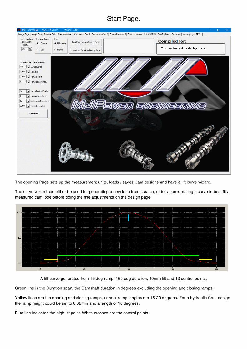
The main Page for designing a new Valve lift profile.
Mirror left side Values will let You design only the left/opening side of the profile, it will then generate a copy of the left
side onto the right side of the profile.
Constant Acceleration Ramps generates a constant acc. Ramp design, unchecked it generates a normal constant
Velocity Ramp design.
Check for 0.1 degree step calculation, only available in the extended version of the Software. It will generate Lift curve
data with 0.1 degree resolution. Because of speed use it mainly for the final steps of the Valve lift profile design.
Change the 0.010 value to a smaller or larger value to help designing the profile.
Show comparison Cam 1, enabled it will display the Cam from the Comparison Cam 1 Page in grey. This is to help
with eg. Designing a copy of a measured Cam profile. The Offset can be adjusted for matching the design profile.
Top row is the Degree settings of the profile.
Second row is the Lift data of the corresponding degree numbers.
Auto-generate updates the display automatically when a Lift or Degree number is changed.
There are settings for Duration, Control points, Ramp lengths and Height, but it is usually best to use the Wizard to set
up these values before beginning of the design itself.
Generate Button will update the Display if Auto generate is not enabled, Print Graphs will open a Printer dialog.
Then there is Checks for display of Velocity, Acceleration and Jerk curves plus their corresponding multiplyers.
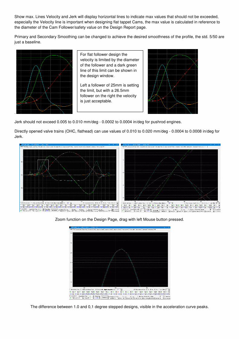
Show max. Lines Velocity and Jerk will display horizontal lines to indicate max values that should not be exceeded,
especially the Velocity line is important when designing flat tappet Cams, the max value is calculated in reference to
the diameter of the Cam Follower/safety value on the Design Report page.
Primary and Secondary Smoothing can be changed to achieve the desired smoothness of the profile, the std. 5/50 are
just a baseline.
.
Jerk should not exceed 0.005 to 0.010 mm/deg - 0.0002 to 0.0004 in/deg for pushrod engines.
Directly opened valve trains (OHC, flathead) can use values of 0.010 to 0.020 mm/deg - 0.0004 to 0.0008 in/deg for
Jerk.
Zoom function on the Design Page, drag with left Mouse button pressed.
The difference between 1.0 and 0,1 degree stepped designs, visible in the acceleration curve peaks.
For flat follower design the
velocity is limited by the diameter
of the follower and a dark green
line of this limit can be shown in
the design window.
Left a follower of 25mm is setting
the limit, but with a 26.5mm
follower on the right the velocity
is just acceptable.
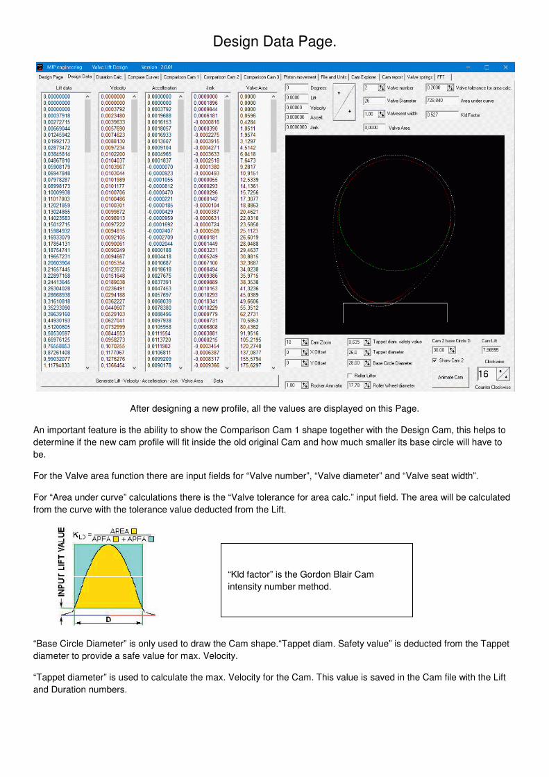
Design Data Page.
After designing a new profile, all the values are displayed on this Page.
An important feature is the ability to show the Comparison Cam 1 shape together with the Design Cam, this helps to
determine if the new cam profile will fit inside the old original Cam and how much smaller its base circle will have to
be.
For the Valve area function there are input fields for “Valve number”, “Valve diameter” and “Valve seat width”.
For “Area under curve” calculations there is the “Valve tolerance for area calc.” input field. The area will be calculated
from the curve with the tolerance value deducted from the Lift.
“Base Circle Diameter” is only used to draw the Cam shape.“Tappet diam. Safety value” is deducted from the Tappet
diameter to provide a safe value for max. Velocity.
“Tappet diameter” is used to calculate the max. Velocity for the Cam. This value is saved in the Cam file with the Lift
and Duration numbers.
“Kld factor” is the Gordon Blair Cam
intensity number method.
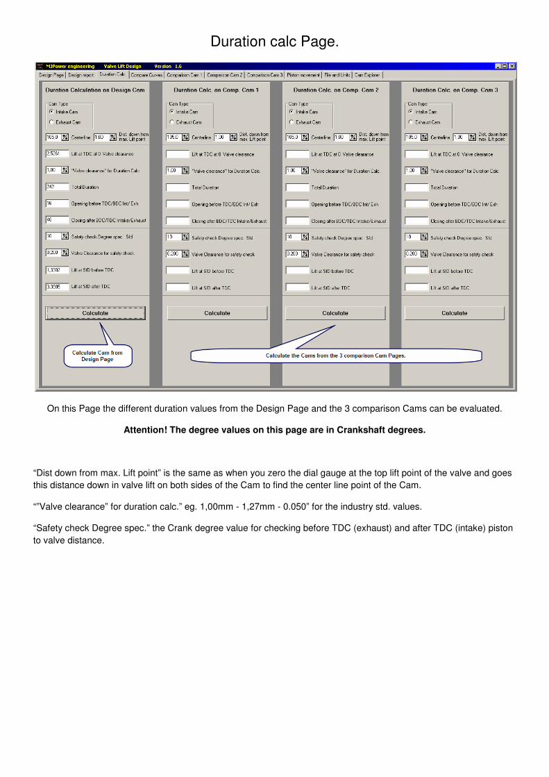
Duration calc Page.
On this Page the different duration values from the Design Page and the 3 comparison Cams can be evaluated.
Attention! The degree values on this page are in Crankshaft degrees.
“Dist down from max. Lift point” is the same as when you zero the dial gauge at the top lift point of the valve and goes
this distance down in valve lift on both sides of the Cam to find the center line point of the Cam.
“”Valve clearance” for duration calc.” eg. 1,00mm - 1,27mm - 0.050” for the industry std. values.
“Safety check Degree spec.” the Crank degree value for checking before TDC (exhaust) and after TDC (intake) piston
to valve distance.
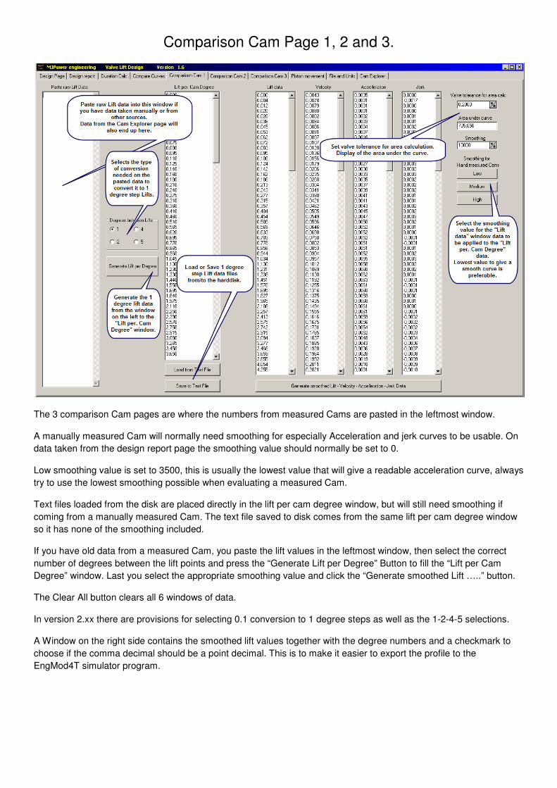
Comparison Cam Page 1, 2 and 3.
The 3 comparison Cam pages are where the numbers from measured Cams are pasted in the leftmost window.
A manually measured Cam will normally need smoothing for especially Acceleration and jerk curves to be usable. On
data taken from the design report page the smoothing value should normally be set to 0.
Low smoothing value is set to 3500, this is usually the lowest value that will give a readable acceleration curve, always
try to use the lowest smoothing possible when evaluating a measured Cam.
Text files loaded from the disk are placed directly in the lift per cam degree window, but will still need smoothing if
coming from a manually measured Cam. The text file saved to disk comes from the same lift per cam degree window
so it has none of the smoothing included.
If you have old data from a measured Cam, you paste the lift values in the leftmost window, then select the correct
number of degrees between the lift points and press the “Generate Lift per Degree” Button to fill the “Lift per Cam
Degree” window. Last you select the appropriate smoothing value and click the “Generate smoothed Lift …..” button.
The Clear All button clears all 6 windows of data.
In version 2.xx there are provisions for selecting 0.1 conversion to 1 degree steps as well as the 1-2-4-5 selections.
A Window on the right side contains the smoothed lift values together with the degree numbers and a checkmark to
choose if the comma decimal should be a point decimal. This is to make it easier to export the profile to the
EngMod4T simulator program.
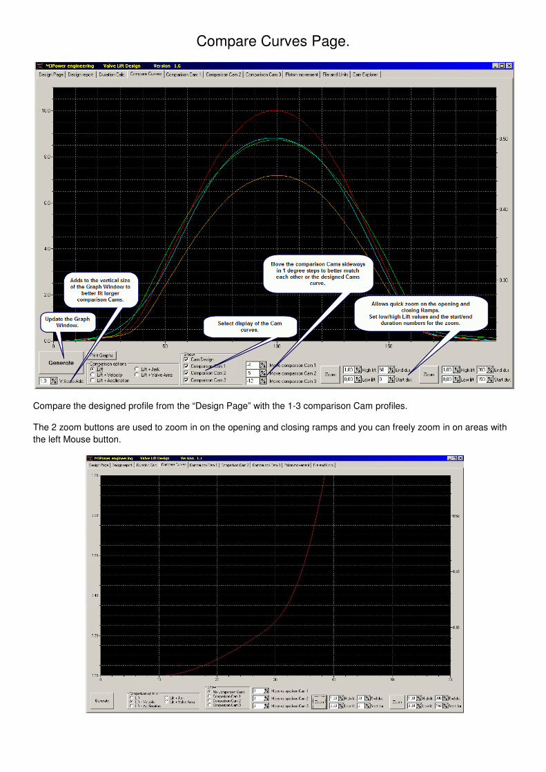
Compare Curves Page.
Compare the designed profile from the “Design Page” with the 1-3 comparison Cam profiles.
The 2 zoom buttons are used to zoom in on the opening and closing ramps and you can freely zoom in on areas with
the left Mouse button.
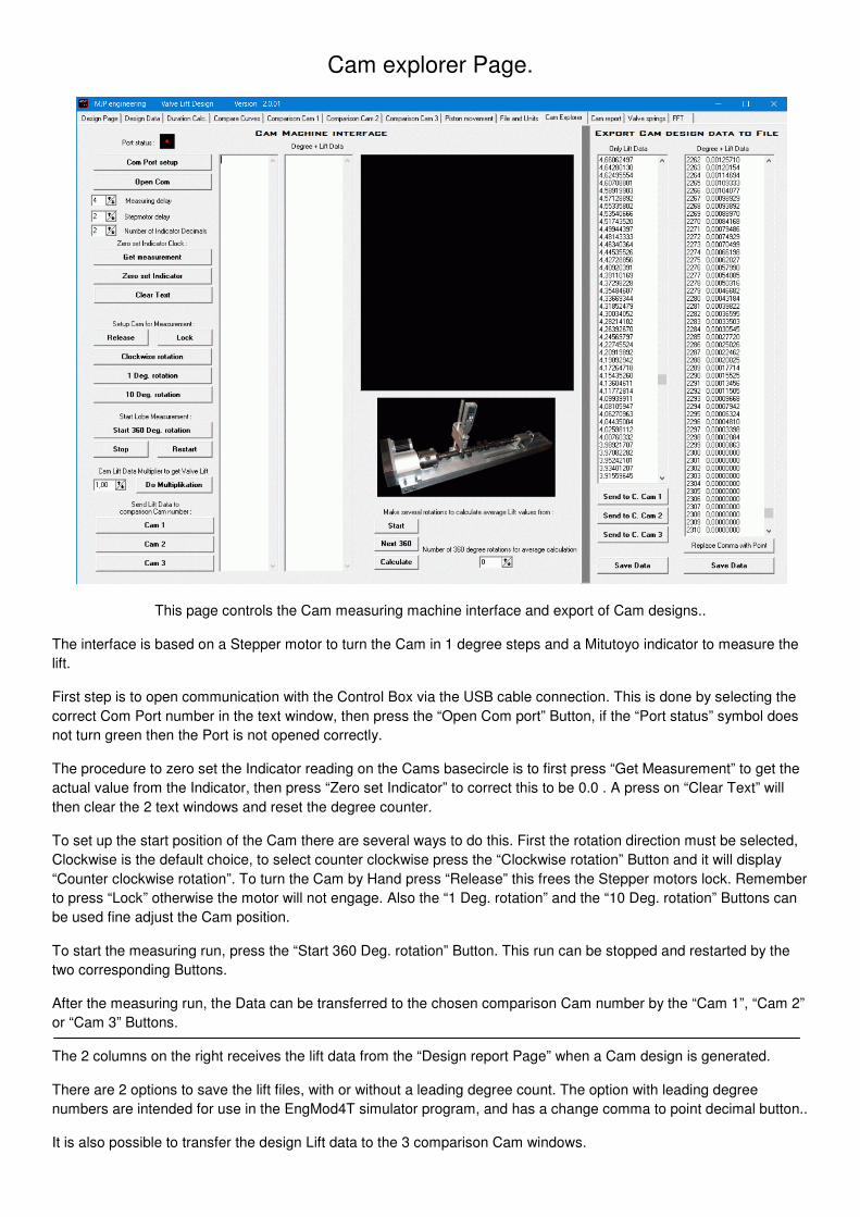
Cam explorer Page.
This page controls the Cam measuring machine interface and export of Cam designs..
The interface is based on a Stepper motor to turn the Cam in 1 degree steps and a Mitutoyo indicator to measure the
lift.
First step is to open communication with the Control Box via the USB cable connection. This is done by selecting the
correct Com Port number in the text window, then press the “Open Com port” Button, if the “Port status” symbol does
not turn green then the Port is not opened correctly.
The procedure to zero set the Indicator reading on the Cams basecircle is to first press “Get Measurement” to get the
actual value from the Indicator, then press “Zero set Indicator” to correct this to be 0.0 . A press on “Clear Text” will
then clear the 2 text windows and reset the degree counter.
To set up the start position of the Cam there are several ways to do this. First the rotation direction must be selected,
Clockwise is the default choice, to select counter clockwise press the “Clockwise rotation” Button and it will display
“Counter clockwise rotation”. To turn the Cam by Hand press “Release” this frees the Stepper motors lock. Remember
to press “Lock” otherwise the motor will not engage. Also the “1 Deg. rotation” and the “10 Deg. rotation” Buttons can
be used fine adjust the Cam position.
To start the measuring run, press the “Start 360 Deg. rotation” Button. This run can be stopped and restarted by the
two corresponding Buttons.
After the measuring run, the Data can be transferred to the chosen comparison Cam number by the “Cam 1”, “Cam 2”
or “Cam 3” Buttons.
The 2 columns on the right receives the lift data from the “Design report Page” when a Cam design is generated.
There are 2 options to save the lift files, with or without a leading degree count. The option with leading degree
numbers are intended for use in the EngMod4T simulator program, and has a change comma to point decimal button..
It is also possible to transfer the design Lift data to the 3 comparison Cam windows.
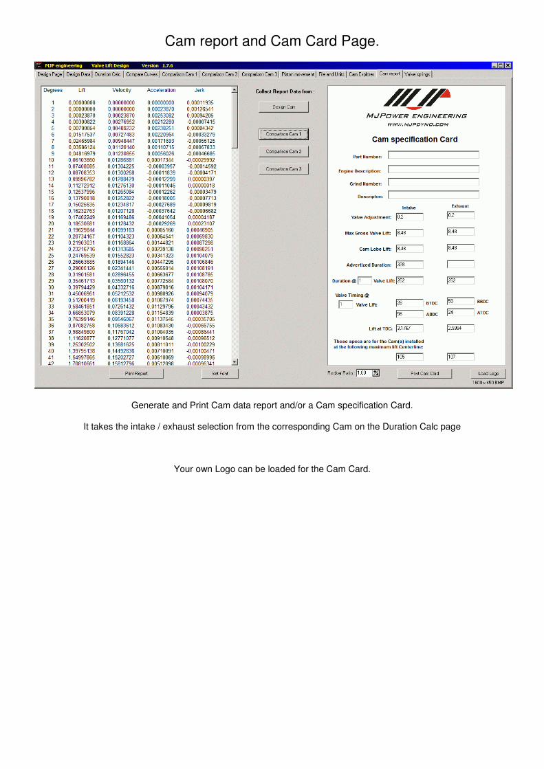
Cam report and Cam Card Page.
Generate and Print Cam data report and/or a Cam specification Card.
It takes the intake / exhaust selection from the corresponding Cam on the Duration Calc page
Your own Logo can be loaded for the Cam Card.
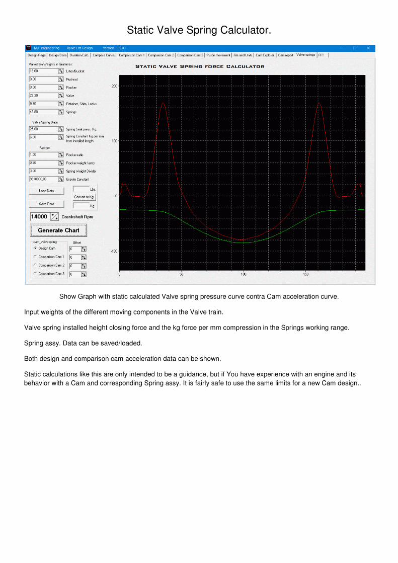
Static Valve Spring Calculator.
Show Graph with static calculated Valve spring pressure curve contra Cam acceleration curve.
Input weights of the different moving components in the Valve train.
Valve spring installed height closing force and the kg force per mm compression in the Springs working range.
Spring assy. Data can be saved/loaded.
Both design and comparison cam acceleration data can be shown.
Static calculations like this are only intended to be a guidance, but if You have experience with an engine and its
behavior with a Cam and corresponding Spring assy. It is fairly safe to use the same limits for a new Cam design..
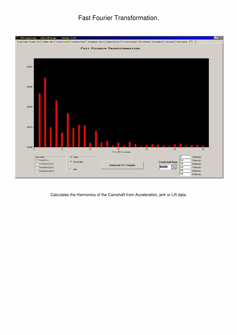
Fast Fourier Transformation.
Calculates the Harmonics of the Camshaft from Acceleration, jerk or Lift data.
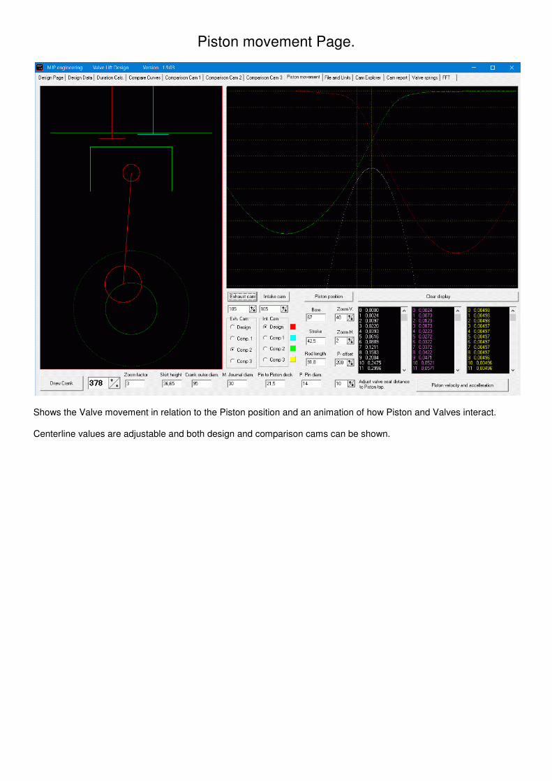
Piston movement Page.
Shows the Valve movement in relation to the Piston position and an animation of how Piston and Valves interact.
Centerline values are adjustable and both design and comparison cams can be shown.