Embed Size (px)
Citation preview
0
Welcome to Engine Repair
4200 Camshaft Position Actuator System
Operation and Diagnosis
Module 6
PPT a1 m6 Final
Copyright 2003 General Motors Corporation
1
The material contained in
this
course component
was accurate and current
at the time of course
development.
2
Objectives
Identify components of the Camshaft Position Actuator System
Describe operation of the Camshaft Position Actuator System
Diagnose operation of the Camshaft Position Actuator System
3
Module 1 Objectives
Describe basic operation of the Camshaft Position Actuator System
Identify benefits of the 4200 Camshaft Position Actuator System
4
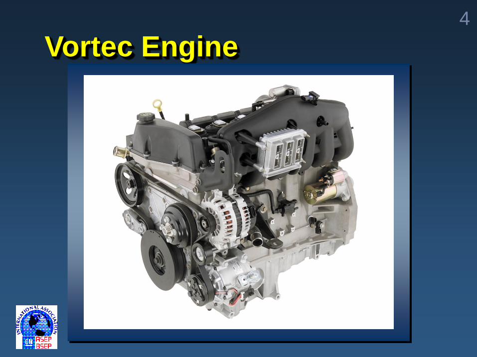
Vortec Engine
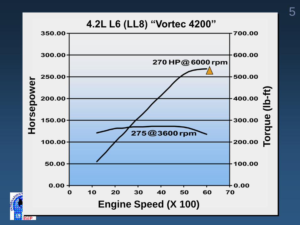
54.2L L6 (LL8) “Vortec 4200”
Engine Speed (X 100)
Ho
rse
po
we
r
To
rqu
e (
lb-f
t)
6
Additional Features
High Compression Ratio 10:1
Electronic Throttle Control
Variable Exhaust Valve Timing
Coil-on-Plug Ignition
Multec II Fuel Injectors
Advanced Powertrain Control
Module
7
4200 Benefits
Increased power output
Broad torque band
Improved mileage
Improved emission control
Eliminates external EGR system
Smoothness and balance
Mass reduction
8
Exhaust Gas Recirculation
Exhaust from exhaust
runners/manifold diverted back to
intake manifold
Traditional method for reducing
oxides of nitrogen (NOx) in fixed
valve timing engines
Reduces NOx creation by reducing
combustion temperatures
External EGR:
9
Internal EGR:
Exhaust charge drawn back
into cylinder during valve
overlap
Exhaust Gas Recirculation cont.
10
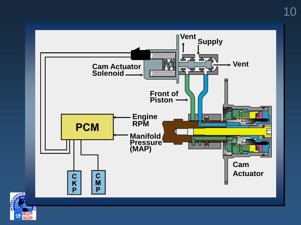
Cam
Actuator
Engine RPM
ManifoldPressure(MAP)
Cam ActuatorSolenoid
VentSupply
Vent
Front of Piston
11
Question
What are some of the
advantages of an inline engine
like the 4200 Vortec?
12
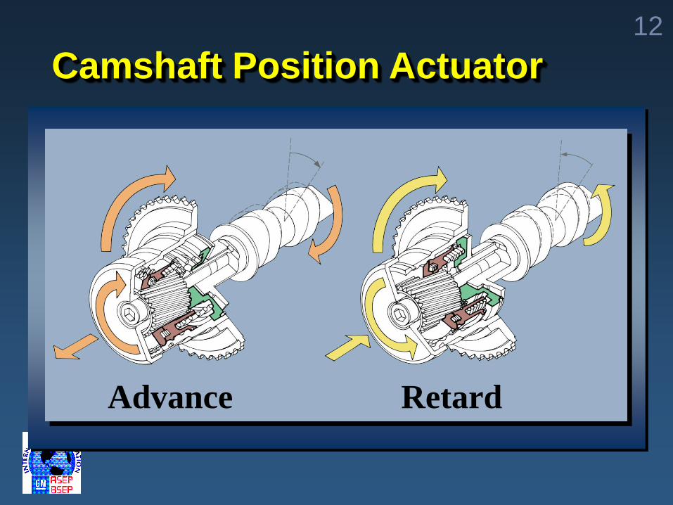
Camshaft Position Actuator
Advance Retard
13
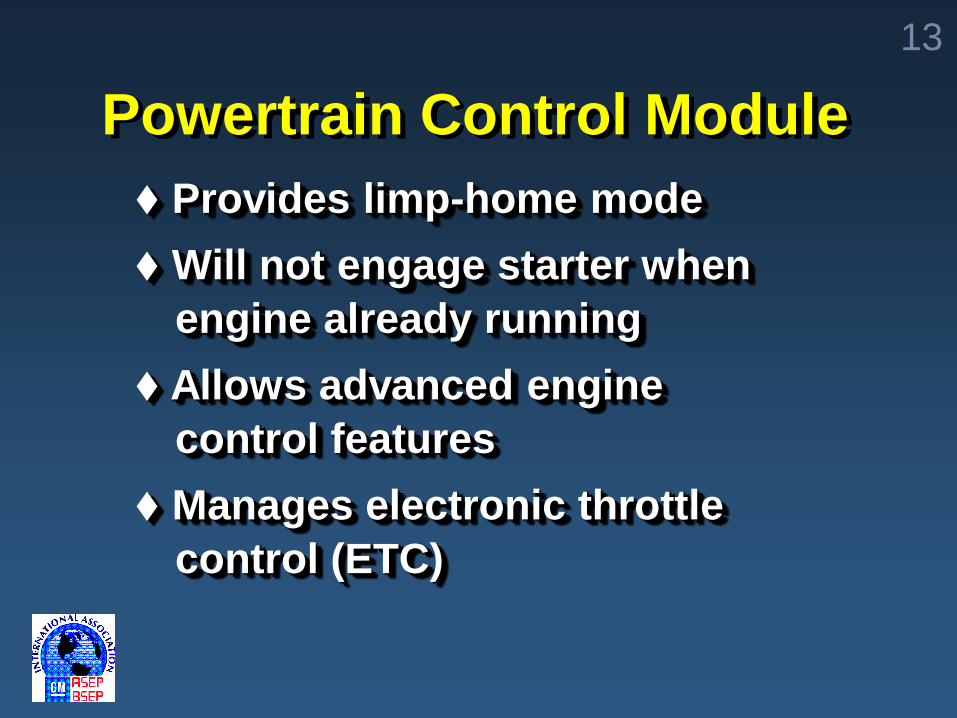
Powertrain Control Module
Provides limp-home mode
Will not engage starter when
engine already running
Allows advanced engine
control features
Manages electronic throttle
control (ETC)
14
Question 3Which cam does the actuator
control and how many cam
degrees of retard does it allow?
A) Exhaust cam, 35º
B) Intake cam, 35º
C) Intake cam, 25º
D) Exhaust cam, 25º
15
Module 2 Objectives
Identify 4200 Camshaft
Position Actuator System
Identify 4200 Camshaft Position
Actuator
Identify 4200 Camshaft Position
Actuator Solenoid Valve
16
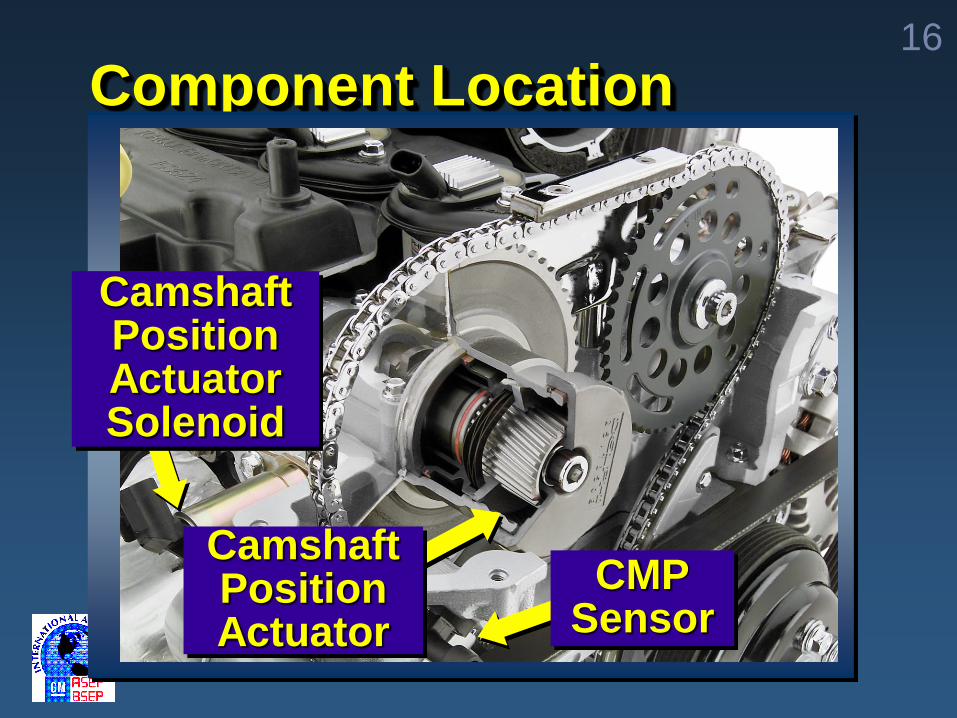
Component Location
Camshaft PositionActuator
CMPSensor
Camshaft Position ActuatorSolenoid
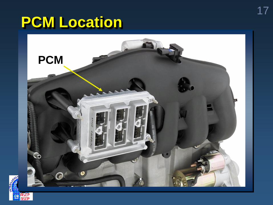
17PCM Location
PCM
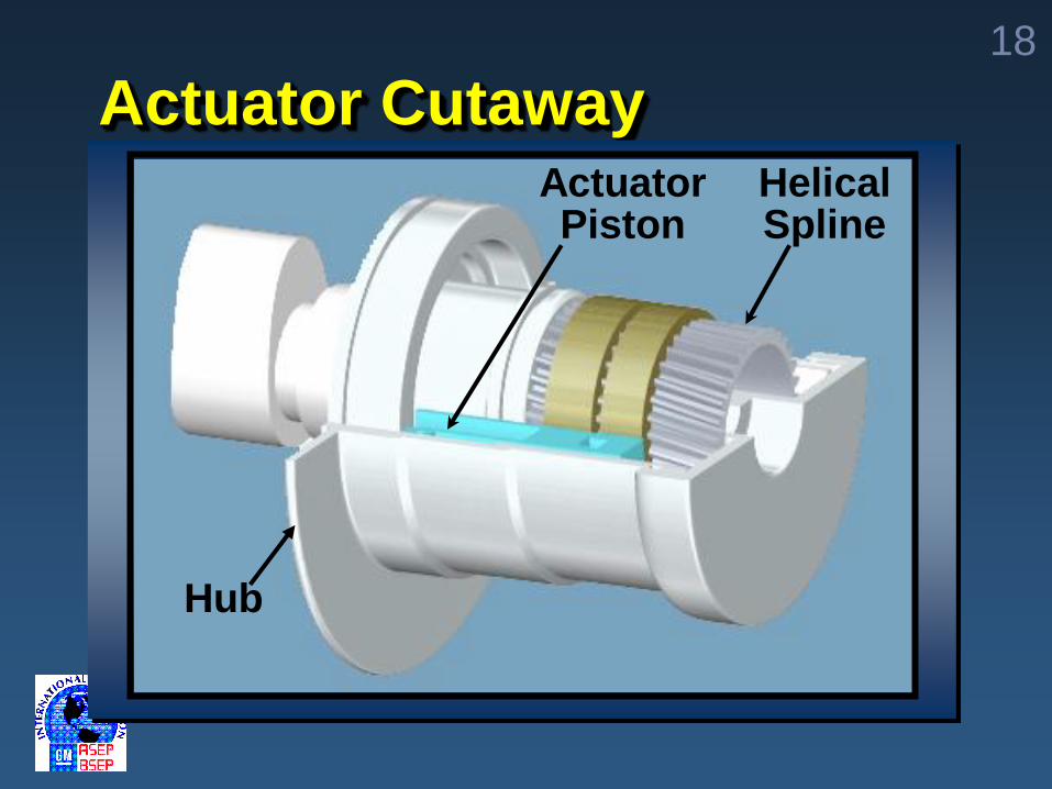
18
Actuator CutawayActuatorPiston
HelicalSpline
Hub
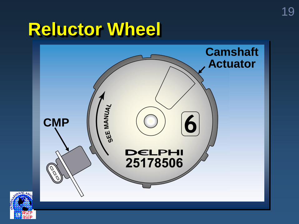
19
Reluctor Wheel
CMP
CamshaftActuator
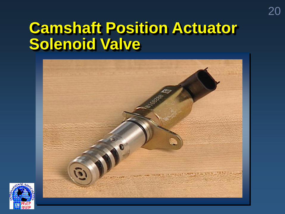
20
Camshaft Position Actuator Solenoid Valve
21
Module 3 Objectives
Identify 4200 Camshaft
Position Actuator System
Components
Describe 4200 Camshaft
Position Actuator System
Operation
22
System Advantages
Improves emissions compared to
conventional EGR system
reduces hydrocarbons by up
to 25%
reduction of oxides of nitrogen
by up to 40%
23
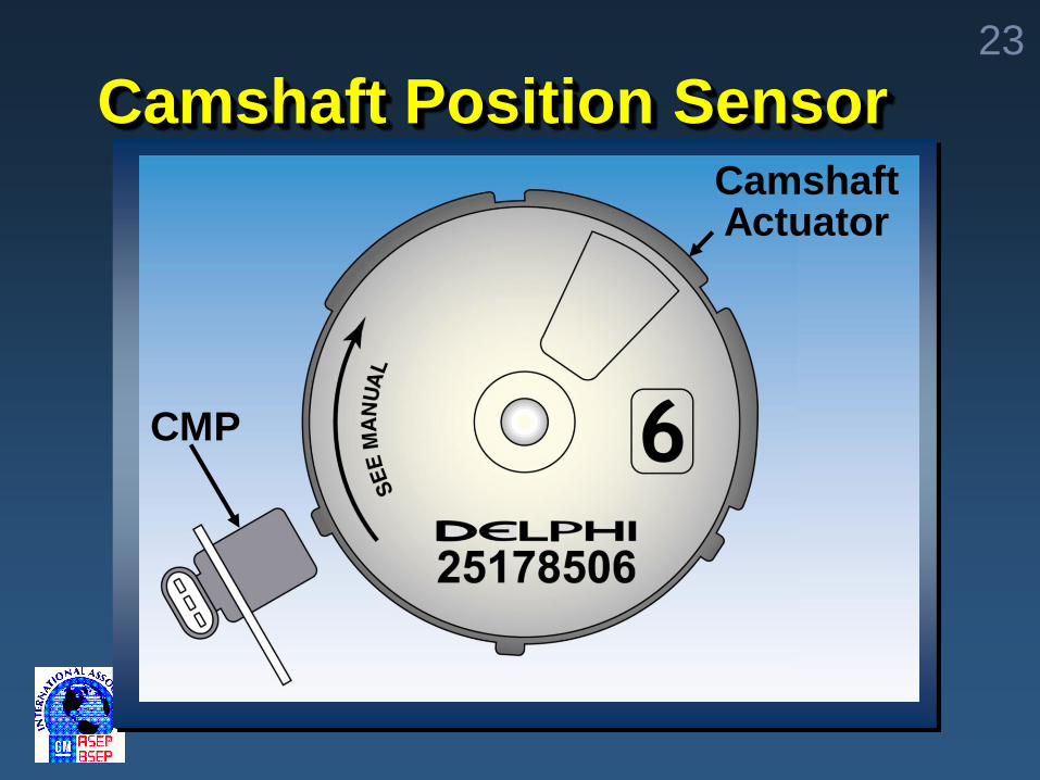
Camshaft Position Sensor
CMP
CamshaftActuator
24
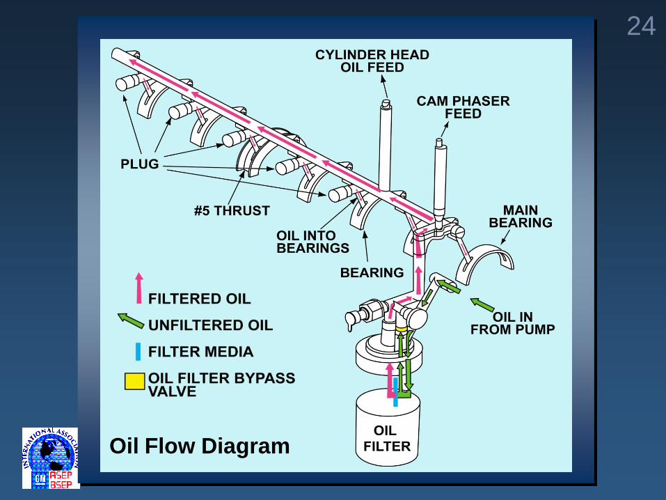
Oil Flow Diagram
25
Camshaft Position
Actuator Purpose
Internal EGR
Fuel economy improvement
Emissions improvement
26
Operation
Operational range
– 25º of exhaust cam timing retard
Camshaft Position Actuator onlyoperates
– above 1200 RPM
Intake charge is diluted with exhaust gas in the combustion chamber
– similar to EGR
– amount of dilution varies as required by PCM

27
Timing
Chain
28
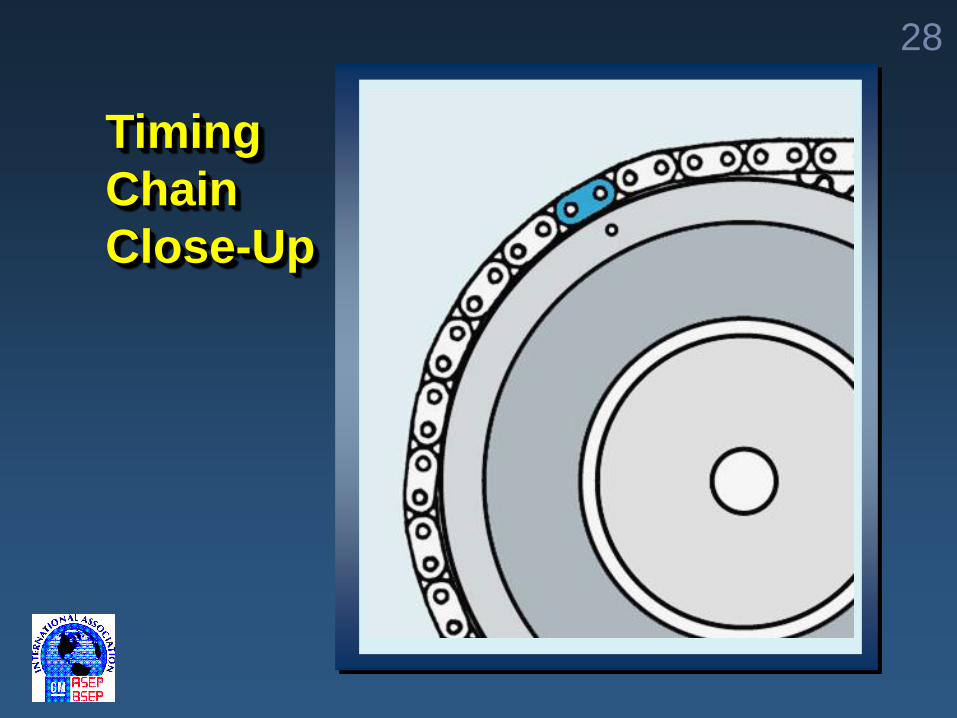
Timing
Chain
Close-Up
29
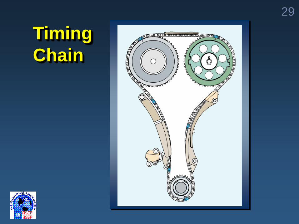
Timing
Chain
30
Module 4 Objective
Diagnose operation of
4200 Camshaft Position
Actuator System
31
Camshaft Position Actuator System DTCs
P0013
– Exhaust Camshaft Position Actuator Control Circuit
P0014
– Exhaust Camshaft Position System Performance
P1345
Crankshaft Position (CKP)Camshaft Position Correlation
32
On-Vehicle Service
Camshaft Position ActuatorSolenoid Valve
– remove power steering pumpfirst
Camshaft Position Actuator
– see Service Information
PCM and wiring
see Service Information
33
Conditions for Setting P0013
1. Low reference circuit - open
2. High control circuit (open
or grounded)
3. Poor connections at the PCM
4. Poor connections at the
solenoid
5. PCM fault
6. Camshaft Position solenoid fault
34
Conditions for Setting P0014
1. Camshaft Position solenoid fault
2. Excessive timing chain play
3. Camshaft Position Actuator
mechanical fault
4. Poor connections at Camshaft
Position Actuator solenoid
harness connector
35
Conditions for Setting P0014
cont.
5. Poor connections at PCM
6. High resistance in Camshaft
Position Actuator solenoid
circuits
36
Visual Checks
Loose sensor
Loose harness connector
Improperly seated sensor
Cracked sensor case
Worn/chafed sensor harness
Oil leaks at connector
37
Other Mechanical Checks
Excessive timing chain wear
Excessive camshaft end play
Excessive crankshaft end play
Proper installation of actuator
assembly
38
Summary
Identified components of the
Camshaft Position Actuator System
Described operation of the
Camshaft Position Actuator System
Diagnosed operation of the
Camshaft Position Actuator System
39
Post-test Question 1Oil flow through the Camshaft
Position solenoid valve is
controlled by the ______.
A) PCM
B) Camshaft Position Actuator
C) Camshaft Position Sensor
D) Reluctor Wheel
40
Post-test Question 2The 4200 I6 Camshaft Position
Actuator system _______.
A) is located on the intake camshaft
B) is pneumatically operated
C) decreases power and torque
D) eliminates the external EGR
system
41
Post-test Question 3
The 4200 I6 eliminates the need for an external EGR System by ________.
A) running a passage through theexhaust manifold and into theintake manifold
B) drawing the exhaust charge into thecylinder during valve overlap
C) pumping exhaust into the cylinderfrom another cylinder
D) connecting the exhaust manifold to the intake manifold
42
Post-test Question 4The Camshaft Position Actuator is
designed to____________.
A) retard exhaust camshaft from 0°
B) advance exhaust camshaft
from 0°
C) retard intake camshaft from 0°
D) advance intake camshaft
from 0°
43
Post-test Question 5When installing the timing chain, the
Camshaft Position Actuator should
be ______.
A) fully advanced
B) fully retarded
C) in any position
D) halfway between advance
and retard
44
Post-test Question 6
The Camshaft Position Actuator
System will only work above _____.
A) 600 RPM
B) 1200 RPM
C) 2200 RPM
D) 2600 RPM
45
Post-test Question 7
The Camshaft Position Actuator
retards exhaust cam timing up
to _______.
A) 15º
B) 20º
C) 25º
D) 30º
46
Post-test Question 8
Oil flow to the Camshaft Position
Actuator is controlled by the ______.
A) Camshaft Position Actuator
Solenoid valve
B) Reluctor wheel
C) CMP sensor
D) Helical spline
47
Post-test Question 9
When physically checking the
Camshaft Position Actuator
movement, how far should it move?
A) 0-3 mm
B) 5-7 mm
C) 14-15 mm
D) 20-22 mm
48
Post-test Question 10
When performing actuator
service, make sure the Camshaft
Actuator is ______.
A) fully advanced, 0º
B) fully retarded, -25º
C) in the middle, 12º
D) fully retarded, 0º
49
Thank you for attending
4200 Camshaft Position Actuator System
Operation and Diagnosis
Copyright 2003 General Motors Corporation