Embed Size (px)
DESCRIPTION
Mixy
Citation preview
Design of a Switched Reluctance Motorfor Mixer-Grinder Application
Shino G.BabuM.Tech Scholar
Department of Electrical EngineeringCollege of Engineering, Trivandrum
Email: [email protected]
Dinesh GopinathLecturer
Department of Electrical EngineeringCollege of Engineering, TrivandrumEmail: [email protected]
Abstract—This paper presents the design procedure of a4-phase, 8/6 Switched Reluctance Motor (SRM) for drivinga mixer-grinder. The conventional motor being used for thisapplication so far is a universal motor and because of its inherentdrawbacks such as the requirement of a mechanical commutatorwith brushes, and absence of easy controllability, the efficiencynever exceeds 70%. This paper suggests a SRM to replace theconventional universal motor for the specific application of mixer-grinder. The step by step procedure for the design of a four phaseswitched reluctance motor is explained. The model is verifiedusing Maxwell software.
Index Terms—Switched Reluctance Motor (SRM), Finite Ele-ment Analysis (FEA), Inductance, Flux-linkage.
I. INTRODUCTION
The mixer-grinder is a commonly used domestic appliancewhich is produced in high volumes. Universal motor is usedas the drive motor in almost all mixer-grinders. The inherenttorque vs speed characteristic of the universal motor suits theload characteristics of mixer-grinder. Once the motor is started,as the mixing/grinding activity is going on, the torque require-ment comes down and the speed increases. Traditionally speedcontrol of universal motors in such appplications is done byvoltage control using manual switches in open loop mode.The lack of control to limit this speed to a set value as tomaintain the quality of the mixer-grinder will not only affectthe output quality of the mixer-grinder, but also necessitate itto operate for more time leading to more power consumption.These motors have low efficiency owing to the presence ofmechanical commutator with brushes.
Recently home appliances are becoming ‘smart’ with micro-computer control and electronic speed control which enhancesthe functionality and efficiency. When electronic speed controlis sought, single-phase or three phase induction motor areusually used with associated power converters. The SwitchedReluctance Motor (SRM) [1] having advantages such as simpleand rugged construction, high efficiency can be an ideal choicefor mixer-grinder applications. Owing to their simple construc-tion they have the potential to become better cost-effectivecompetitor to squirrel cage induction motors in applicationswith high-volume production such as the mixer/grinders. Theunipolar nature ofthe drive circuit gives it the capability forhigh speed operation. In this paper the design of a four
phase switched reluctance motor for driving a mixer-grinderis presented.
II. SWITCHED RELUCTANCE MOTOR
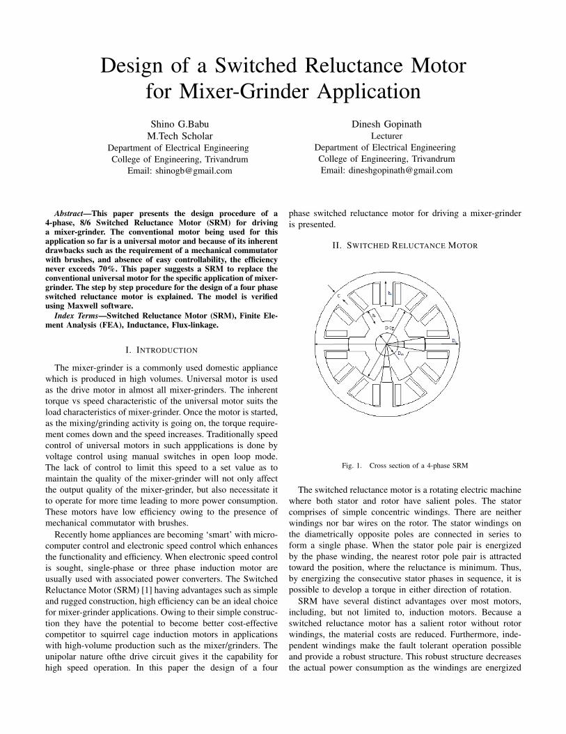
Fig. 1. Cross section of a 4-phase SRM
The switched reluctance motor is a rotating electric machinewhere both stator and rotor have salient poles. The statorcomprises of simple concentric windings. There are neitherwindings nor bar wires on the rotor. The stator windings onthe diametrically opposite poles are connected in series toform a single phase. When the stator pole pair is energizedby the phase winding, the nearest rotor pole pair is attractedtoward the position, where the reluctance is minimum. Thus,by energizing the consecutive stator phases in sequence, it ispossible to develop a torque in either direction of rotation.
SRM have several distinct advantages over most motors,including, but not limited to, induction motors. Because aswitched reluctance motor has a salient rotor without rotorwindings, the material costs are reduced. Furthermore, inde-pendent windings make the fault tolerant operation possibleand provide a robust structure. This robust structure decreasesthe actual power consumption as the windings are energized

and de-energized only when required. It also has high torque-to-inertia ratio and high starting torque without the problemof in-rush current. With other motor applications, this in-rushcurrent during start up might cause the line voltage to dipmomentarily, which adversely affects the power quality andcan pose a problem in meeting government regulations.
There can be some drawbacks to using SRM technologywhich need to be examined. For example, SRM operationrequires knowledge of rotor position. Therefore, SRMs usuallymust include sensors, which can increase the overall costof the system. Another drawback of SRMs is the need forsophisticated acoustic noise control due to the vibrationsinherent with operation and application needs to be unaffectedby torque ripple or control.
III. DESIGN SPECIFICATIONS
Recently, Switched Reluctance Motor (SRM) has beenresearched to use in home and industrial appliance with thefollowing advantages [2]. Because a switched reluctance motorhas a salient rotor without rotor windings, the material costsare reduced. Furthermore, independent windings make thefault tolerant operation possible and provide a robust structure.This robust structure decreases the actual power consumptionas the windings are energized and de-energized only whenrequired. It also has high torque-to-inertia ratio and highstarting torque without the problem of in-rush current. Withother motor applications, this in-rush current during startup might cause the line voltage to dip momentarily, whichadversely affects the power quality and can pose a problem inmeeting government regulations.
A. Output Power
Normally mixer-grinder used in domestic appliance hasoutput power over the range 280-500W. Here we have chosenthe output power as 500W.
B. Speed
The speed is chosen as 1500 rpm and it is belt driven. Sinceit is belt driven lower rpm can be achieved.
C. Supply voltage
A consideration to the voltage level that can be used in SRMcan be the device cost, which in this device is a dc voltage.It is well known that the device cost increases drasticallywith voltage. As the availabilty of low voltage high currentMOSFET’s are at cheap price.It is found to use a low dcvoltage of 50V.
Sl.no Machine Details Specification1) Power output 500 W2) Speed 1500 rpm3) Current 11.765 A4) Voltage 50 V5) Torque Developed 3.18 N-m
IV. DESIGN OF GEOMETRICAL DIMENSION
This section deals with the selection of major dimension ofSRM using analytical method.
A. Outer dimension
The outer diameter of the stator and the effective lengthof iron has been chosen as 120mm and 80mm, because theseare the dimension of the commercial motor used for homeapplications.
B. Selection of number of phases
SRM is available with various number of phases(1-phase,2-phase,3-phase,4-phase). The increase in the number of phasesdecreases the torque ripple and viceversa. The problem oftorque dips can be reduced by increasing the number ofstrokes per rotation, which leads to a smaller stroke angle, ε.It can be achieved by increasing the rotor pole number orthe phase number. Increase in rotor pole number reduces theinductance ratio (the ratio of aligned to unaligned inductance).Low inductance ratio increases the controller volt-ampererequirement and decreases the specific output. The increasein number of phases will complicate the controller circuit andincrease the switching losses. With the trade off between thisdata, the number of phases is chosen as 4.
C. Selection of stator and rotor poles
The rotor pole number (Nr) is selected such that
Nr = Ns − 2. (1)
where (Ns) is the number of stator pole. The combinationNr=Ns is not recommended, since all position will be alignedand hence creates starting problem. The number of strokesper revolution is higher for machines with Nr>Ns. Whereasinductance ratio is higher for machines with Nr<Ns. Thestator has two or more poles per phase in order to balance theradial forces produced by each phase [3]. The most suitabletype of four phase SRM topology is 8/6, i.e 8 stator poles and6 rotor poles. Two stator poles of one phase are located inopposite sides of the rotor and their windings are connectedin series.
D. Stator and rotor pole angle selection
The three important factors that governs the selection ofstator pole arc (βs) and rotor pole arc (βr) are,
βs ≤ βr (2)
βs ≥ ε (3)
2πNr− βs ≤ βr (4)
Equation(2) is to be satisfied to maximize the aligned induc-tance, (3) is to be satisfied to achieve starting torque at all rotorpositions and (4) is to be satisfied to avoid overlap betweenpoles in unaligned condition. Based on the above factors afeasible triangle is drawn and shown in Fig 2.
Based on the feasible triangle the value of βs and βr ischosen as 18o and 21o.
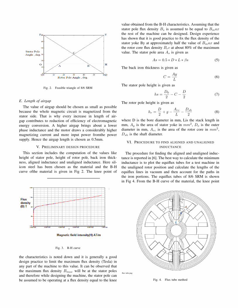
Fig. 2. Feasible triangle of 8/6 SRM
E. Length of airgap
The value of airgap should be chosen as small as possiblebecause the whole magnetic circuit is magnetized from thestator side. That is why every increase in length of air-gap contributes to reduction of efficiency of electromagneticenergy conversion. A higher airgap brings about a lowerphase inductance and the motor draws a considerably highermagnetizing current and more input power fromthe powersupply. Hence the airgap length is chosen as 0.5mm.
V. PRELIMINARY DESIGN PROCEDURE
This section includes the computation of the values likeheight of stator pole, height of rotor polr, back iron thick-ness, aligned inductance and unaligned inductance. Here sil-icon steel has been chosen as the material and the B-Hcurve ofthe material is given in Fig 2. The knee point of
Fig. 3. B-H curve
the characteristics is noted down and it is generally a gooddesign practice to limit the maximum flux density (Tesla) inany part of the machine to this value. It can be observed thatthe maximum flux density Bmax will be at the stator polesand therefore while designing the machine, the stator pole canbe assumed to be operating at a flux density equal to the knee
value obtained from the B-H characteristics. Assuming that thestator pole flux density Bs is assumed to be equal to Bmaxthe rest of the machine can be designed. Design experiencehas shown that it is good practice to fix the flux density of thestator yoke By at approximately half the value of Bmax andthe rotor core flux density Brc at about 80% of the maximumvalue. The stator pole area As is given as
As = 0.5 ∗D ∗ L ∗ βs (5)
The back iron thickness is given as
C =Ay
L(6)
The stator pole height is given as
hs =D0
2− C − D
2(7)
The rotor pole height is given as
hr =D
2+ g − Arc
L− Dsh
2(8)
where D is the bore diameter in mm, Lis the stack length inmm, Ay is the area of stator yoke in mm2, Do is the outerdiameter in mm, Arc is the area of the rotor core in mm2,Dsh is the shaft diameter.
VI. PROCEDURE TO FIND ALIGNED AND UNALIGNEDINDUCTANCE
The procedure for finding the aligned and unaligned induc-tance is reported in [6]. The best way to calculate the minimuminductance is to plot the equiflux tubes for a test machine inthe unaligned rotor position and calculate the lengths of theequiflux lines in vacuum and then account for the paths inthe iron portions. The equiflux tubes of 8/6 SRM is shownin Fig 4. From the B-H curve of the material, the knee point
flux tube.png
Fig. 4. Flux tube method
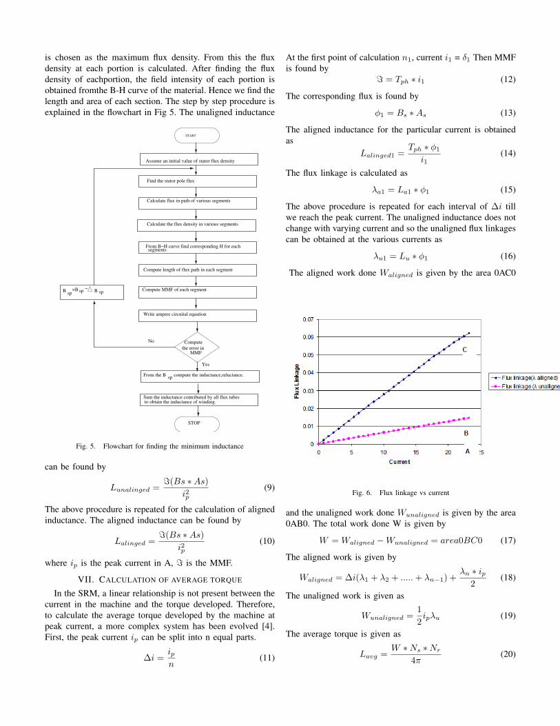
is chosen as the maximum flux density. From this the fluxdensity at each portion is calculated. After finding the fluxdensity of eachportion, the field intensity of each portion isobtained fromthe B-H curve of the material. Hence we find thelength and area of each section. The step by step procedure isexplained in the flowchart in Fig 5. The unaligned inductance
START
Compute length of flux path in each segment
Compute MMF of each segment
Write ampere circuital equation
Compute
the error in MMF
From the Bsp
compute the inductance,reluctance.
Sum the inductance contributed by all flux tubes to obtain the inductance of winding.
STOP
Bsp
=B sp−
B sp
Yes
No
Assume an initial value of stator flux density
Find the stator pole flux
Calculate flux in path of various segments
Calculate the flux density in various segments
From B−H curve find corresponding H for each segments
Fig. 5. Flowchart for finding the minimum inductance
can be found by
Lunalinged ==(Bs ∗As)
i2p(9)
The above procedure is repeated for the calculation of alignedinductance. The aligned inductance can be found by
Lalinged ==(Bs ∗As)
i2p(10)
where ip is the peak current in A, = is the MMF.
VII. CALCULATION OF AVERAGE TORQUE
In the SRM, a linear relationship is not present between thecurrent in the machine and the torque developed. Therefore,to calculate the average torque developed by the machine atpeak current, a more complex system has been evolved [4].First, the peak current ip can be split into n equal parts.
∆i =ipn
(11)
At the first point of calculation n1, current i1 = δ1 Then MMFis found by
= = Tph ∗ i1 (12)
The corresponding flux is found by
φ1 = Bs ∗As (13)
The aligned inductance for the particular current is obtainedas
Lalinged1 =Tph ∗ φ1
i1(14)
The flux linkage is calculated as
λa1 = La1 ∗ φ1 (15)
The above procedure is repeated for each interval of ∆i tillwe reach the peak current. The unaligned inductance does notchange with varying current and so the unaligned flux linkagescan be obtained at the various currents as
λu1 = Lu ∗ φ1 (16)
The aligned work done Waligned is given by the area 0AC0
Fig. 6. Flux linkage vs current
and the unaligned work done Wunaligned is given by the area0AB0. The total work done W is given by
W = Waligned −Wunaligned = area0BC0 (17)
The aligned work is given by
Waligned = ∆i(λ1 + λ2 + .....+ λn−1) +λn ∗ ip
2(18)
The unaligned work is given as
Wunaligned =12ipλu (19)
The average torque is given as
Lavg =W ∗Ns ∗Nr
4π(20)

VIII. ANALYTICAL RESULTS
The above procedures and formulae has been performed andthe following results has been obtained.
Fig. 7. Inductance profile
Sl.no Parameter Value1) Stator Pole Arc 18 deg2) Rotor Pole Arc 21 deg3) Height of stator pole 17 mm4) Height of rotor pole 19 mm5) Alligned inductance 2.7 mH6) Unalligned inductance 0.6 mH7) Outer Diameter 120mm8) Stack Length 80mm9) Bore Diameter 66mm
10) Shaft Diameter 15mm11) Air gap length 0.5mm12) Turns per phase 5013) Copper loss 74W
IX. DESIGN VERIFICATION USING FINITE ELEMENTANALYSIS
Finite Element Analysis (FEA) is used to predict the torqueproduced at various currents as well as to calculate the phaseinductance. FEA is using the software Maxwell. The fluxdistribution during aligned and unaligned position is shownin Fig 8 and Fig 9.
Fig. 8. Flux distribution in aligned position
Fig. 9. Flux distribution in unaligned position
The inductance profile is shown in Fig 10 and the torque isshown in Fig 11.
Fig. 10. Inductance profile
Fig. 11. Torque Vs Rotor angle

X. RESULTS COMPARISION
The below table shows the results obtained from analyticalcomputation and FEA, which is closely related.
Aligned indutance Unaligned inductanceAnalytical 2.77mH 0.67mH
FEA 3.15mH 0.98mH
XI. CONCLUSION
In this paper, the design of switched reluctance motor forpowering mixer-grinder is described. The analytical designresults have been obtained. It is verified and compared withFEA results, which are closely related. The work is in progressto fabricate the machine and to design a suitable converter forthe machine.
REFERENCES
[1] P. J. Lawrenson, J. M Stephenson, “Variable speed switched reluctancemotor drives” IEEE Proceedings, vol. 127, pp. 253-265, July. 1980.
[2] S. Ekram , K. R. Rajagopal, “Design and development of a highefficiency switched reluctance motor for a mixer application” Annualconference of the IEEE Industrial Electronics Society ,pp. 193-197, Nov.2007.
[3] T.J.E Miller, “Switched reluctance motor and their control”, Magnaphysics,Oxford 1992.
[4] R.Krishnan, “Switched Reluctance Motor Drives”, CRC Press, Jan 2001.[5] M.N.Anwar, “A comprehensive design methodology for switched re-
luctance machines” IEEE Trans on industry applications, vol. 41, pp.4069-4071, Dec. 2001.
[6] N. K. Sheth, K. R. Rajagopal, “Calculation of the Flux-Linkage Charac-teristics of a Switched Reluctance Motor by Flux Tube Method” IEEETrans on magnetics, vol. 41, pp. 1684-1692, Dec. 2001.