Embed Size (px)
Citation preview

32bitLogicLogic
16bitLogicLogic
4chAnalogAnalog
Mixed Signal Oscilloscope
High speed waveform acquisition and history memory Advanced trigger functions
Powerful dual-window waveform zoom, search, and analysis Lightweight and compact
DL9000 Series MSO Models
Bulletin 7013-31Ewww.yokogawa.com/tm/... and subscribe to “Newswave,”our free e-mail newsletter
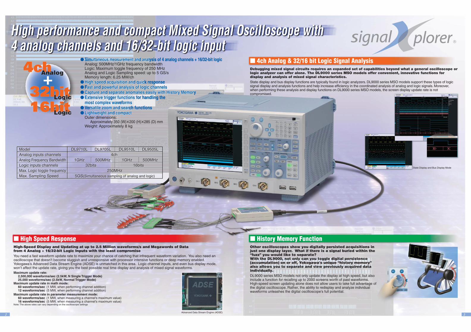
Model DL9710L DL9705L DL9510L DL9505LAnalog inputs channels 4ch Analog Frequency Bandwidth 1GHz 500MHz 1GHz 500MHzLogic inputs channels 32bits 16bitsMax. Logic toggle frequency 250MHzMax. Sampling Speed 5GS(Simultaneous sampling of analog and logic)
Model DL9710L DL9705L DL9510L DL9505LAnalog inputs channels 4ch Analog Frequency Bandwidth 1GHz 500MHz 1GHz 500MHzLogic inputs channels 32bits 16bitsMax. Logic toggle frequency 250MHzMax. Sampling Speed 5GS(Simultaneous sampling of analog and logic)
32
32bitLogicLogic
16bitLogicLogic
4chAnalogAnalog
Simultaneous measurement and analultaneous measurement and analysis of 4 analog channels + 16/32-bit logic
High speed acquisition and quicHigh speed acquisition and quick response Fast and poast and powerful analwerful analysis of logic cysis of logic channelshannelsCapture and separate anomalies easilCapture and separate anomalies easily with History with History Memory MemoryExtensive trigExtensive trigger functions fer functions for handling the
most complemost complex wax waveformsormsVersatile zoom and searsatile zoom and search functionsLightweight and compact Lightweight and compact
Simultaneous measurement and analysis of 4 analog channels + 16/32-bit logic Analog: 500MHz/1GHz frequency bandwidthLogic: Maximum toggle frequency of 250 MHzAnalog and Logic Sampling speed: up to 5 GS/sMemory length: 6.25 MW/ch
High speed acquisition and quick response Fast and powerful analysis of logic channelsCapture and separate anomalies easily with History MemoryExtensive trigger functions for handling the
most complex waveformsVersatile zoom and search functionsLightweight and compact
Outer dimensions: Approximately 350 (W)200 (H)285 (D) mmWeight: Approximately 8 kg
4ch Analog & 32/16 bit Logic Signal Analysis
Advanced Data Stream Engine (ADSE)
State Display and Bus Display Mode
High Speed ResponseHigh-Speed Display and Updating at up to 2.5 Million waveforms/s and Megawords of Datafrom 4 Analog + 16/32-bit Logic Inputs with the least compromiseYou need a fast waveform update rate to maximize your chance of catching that infrequent waveform variation. You also need an oscilloscope that doesn’t become sluggish and unresponsive with processor intensive functions or deep memory enabled. Yokogawa’s Advanced Data Stream Engine (ADSE) is unmatched in this area. Logic channel inputs, and even bus display mode, won’t affect the update rate, giving you the best possible real time display and analysis of mixed signal waveforms.Maximum update rate:
2,500,000 waveforms/sec (2.5kW, N Single Trigger Mode) 25,000 waveforms/sec (2.5kW, Normal Trigger Mode)
Maximum update rate in math mode:60 waveforms/sec (1 MW, when performing channel addition)12 waveforms/sec (5 MW, when performing channel addition)
Maximum update rate in parameter measurement mode:60 waveforms/sec (1 MW, when measuring a channel's maximum value)16 waveforms/sec (5 MW, when measuring a channel's maximum value)
Note: The above rates can vary depending on the oscilloscope settings
History Memory FunctionOther oscilloscopes show you digitally persisted acquisitions in just one display layer. What if there is a signal buried within the “fuzz” you would like to separate?With the DL9000, not only can you toggle digital persistence (accumulation) on or off, Yokogawa's unique “history memory” also allows you to separate and view previously acquired data individually.DL9000 series MSO models not only update the display at high speed, but also include a function for recalling up to 2000 screens worth of past waveforms.High-speed screen updating alone does not allow users to take full advantage of the digital oscilloscope. Rather, the ability to redisplay and analyze individual waveforms unleashes the digital oscilloscope's full potential.
4ch Analog & 32/16 bit Logic Signal AnalysisDebugging mixed signal circuits requires an expanded set of capabilities beyond what a general oscilloscope or logic analyzer can offer alone. The DL9000 series MSO models offer convenient, innovative functions for display and analysis of mixed signal characteristics.State display and bus display functions are typically found in logic analyzers. DL9000 series MSO models support these types of logic signal display and analysis functions and help increase efficiency in the coordinated analysis of analog and logic signals. Moreover, when performing these analysis and display functions on DL9000 series MSO models, the screen display update rate is not compromised.
4 5
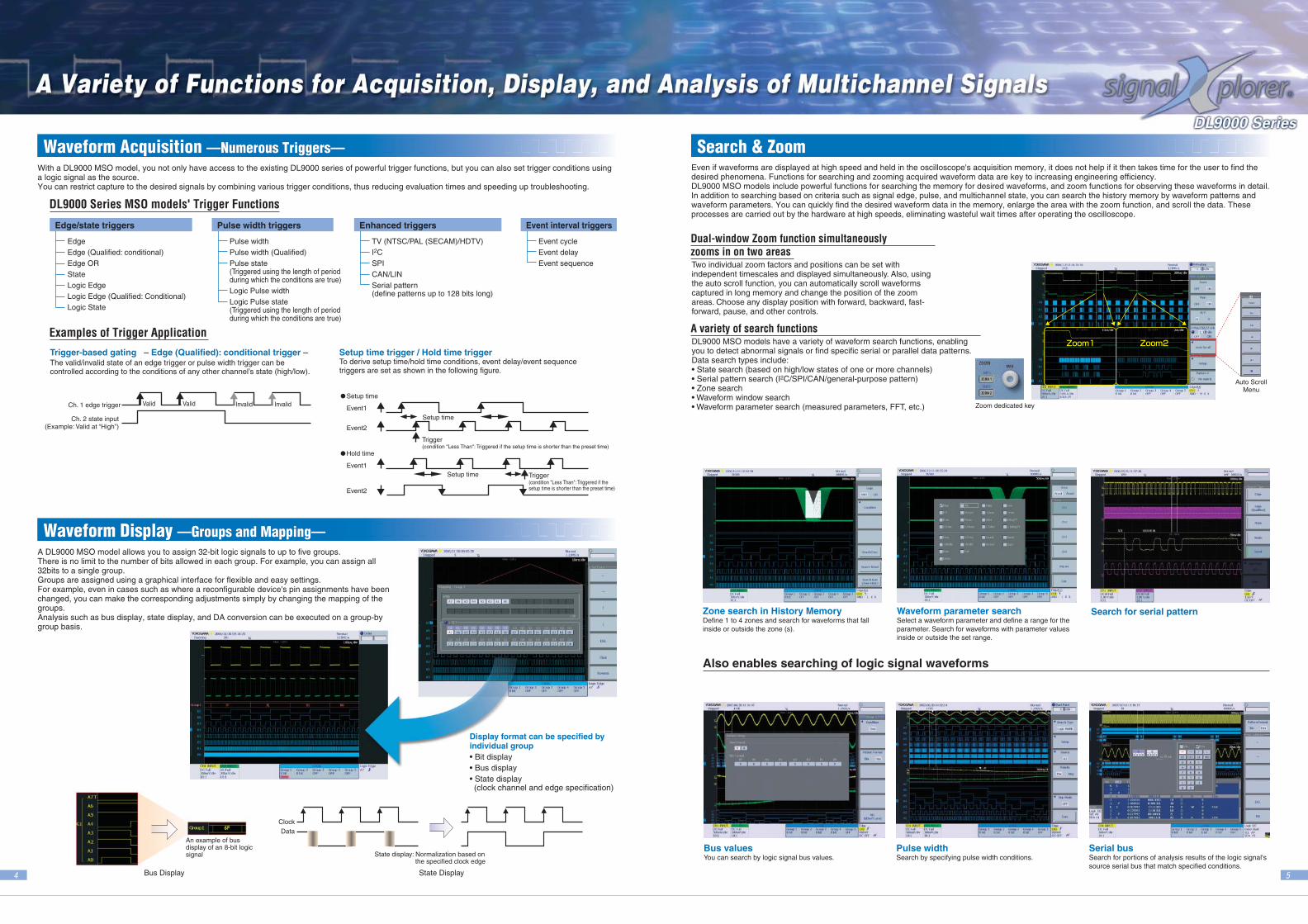
Even if waveforms are displayed at high speed and held in the oscilloscope's acquisition memory, it does not help if it then takes time for the user to find the desired phenomena. Functions for searching and zooming acquired waveform data are key to increasing engineering efficiency. DL9000 MSO models include powerful functions for searching the memory for desired waveforms, and zoom functions for observing these waveforms in detail. In addition to searching based on criteria such as signal edge, pulse, and multichannel state, you can search the history memory by waveform patterns and waveform parameters. You can quickly find the desired waveform data in the memory, enlarge the area with the zoom function, and scroll the data. These processes are carried out by the hardware at high speeds, eliminating wasteful wait times after operating the oscilloscope.
Zoom1 Zoom2
Also enables searching of logic signal waveforms
Auto ScrollMenu
Zoom dedicated key
Search for serial patternZone search in History MemoryDefine 1 to 4 zones and search for waveforms that fall inside or outside the zone (s).
Waveform parameter searchSelect a waveform parameter and define a range for the parameter. Search for waveforms with parameter values inside or outside the set range.
Bus valuesYou can search by logic signal bus values.
Pulse widthSearch by specifying pulse width conditions.
Serial busSearch for portions of analysis results of the logic signal's source serial bus that match specified conditions.
With a DL9000 MSO model, you not only have access to the existing DL9000 series of powerful trigger functions, but you can also set trigger conditions using a logic signal as the source. You can restrict capture to the desired signals by combining various trigger conditions, thus reducing evaluation times and speeding up troubleshooting.
DL9000 Series MSO models' Trigger Functions
Examples of Trigger Application
EdgeEdge (Qualified: conditional)Edge ORStateLogic EdgeLogic Edge (Qualified: Conditional)Logic State
Pulse widthPulse width (Qualified)Pulse state(Triggered using the length of period during which the conditions are true)Logic Pulse widthLogic Pulse state(Triggered using the length of period during which the conditions are true)
TV (NTSC/PAL (SECAM)/HDTV)I2CSPICAN/LINSerial pattern(define patterns up to 128 bits long)
Event cycleEvent delayEvent sequence
Trigger-based gating – Edge (Qualified): conditional trigger –The valid/invalid state of an edge trigger or pulse width trigger can be controlled according to the conditions of any other channel’s state (high/low).
Setup time trigger / Hold time triggerTo derive setup time/hold time conditions, event delay/event sequence triggers are set as shown in the following figure.
A DL9000 MSO model allows you to assign 32-bit logic signals to up to five groups.There is no limit to the number of bits allowed in each group. For example, you can assign all 32bits to a single group.Groups are assigned using a graphical interface for flexible and easy settings. For example, even in cases such as where a reconfigurable device's pin assignments have been changed, you can make the corresponding adjustments simply by changing the mapping of the groups.Analysis such as bus display, state display, and DA conversion can be executed on a group-by group basis.
Display format can be specified by individual group• Bit display• Bus display• State display(clock channel and edge specification)
Waveform Acquisition —Numerous Triggers—Waveform Acquisition —Numerous Triggers— Search & ZoomSearch & Zoom
Waveform Display —Groups and Mapping—Waveform Display —Groups and Mapping—
An example of bus display of an 8-bit logic signal
Bus Display State Display
ClockData
State display: Normalization based on the specified clock edge
Setup time
Event1
Event2
Trigger(condition "Less Than": Triggered if the setup time is shorter than the preset time)
Setup time
Hold time
Event1
Event2
Setup time Trigger(condition "Less Than": Triggered if the setup time is shorter than the preset time)
Ch. 1 edge trigger Valid Valid Invalid Invalid
Ch. 2 state input(Example: Valid at “High”)
Edge/state triggers Pulse width triggers Enhanced triggers Event interval triggers
Two individual zoom factors and positions can be set with independent timescales and displayed simultaneously. Also, using the auto scroll function, you can automatically scroll waveforms captured in long memory and change the position of the zoom areas. Choose any display position with forward, backward, fast-forward, pause, and other controls.
Dual-window Zoom function simultaneously zooms in on two areas
DL9000 MSO models have a variety of waveform search functions, enabling you to detect abnormal signals or find specific serial or parallel data patterns.Data search types include: • State search (based on high/low states of one or more channels)• Serial pattern search (I2C/SPI/CAN/general-purpose pattern)• Zone search• Waveform window search• Waveform parameter search (measured parameters, FFT, etc.)
A variety of search functions
6 7
Time domain waveform parameters such as pulse width, interval, and delay can be measured automatically for logic signals as well.
You can automatically measure waveform parameters, including max., min., peak-peak, pulse width, period, frequency, rise time, fall time, and duty ratio.
Waveform parameters can be calculated repeatedly every screen or period, and the statistical results (mean, maximum, minimum, standard deviation, etc.) of the waveform parameters can be displayed. Automated measurement of waveform parameters and statistical computations can also be performed on waveform data in history memory.
I2Cバス解析画面例
Jitter
Eye Width EyeHeight
Eye Pattern AnalysisThis function automatically measures the waveform parameters of an eye pattern. Unlike the waveform parameter measurement of earlier DL series oscilloscopes, DL9000 MSO models can calculate parameters based on the eye pattern formed by the crossings of two or more waveforms.
Effective power supply analysis can be easily carried out using the waveform computation, statistical computation and automatic parameter measurement functions.Harmonic analysis of power supply currents based on EN61000-3-2 is also supported.
[Main Functions]· Measurement and statistical computation of
parameters specific to power supply analysis such as electric energy and power factor
· Measurement of switching loss with history statistics
· Computation functions required for power supply analysis such as active power, impedance, and Joule-integral
· Harmonic analysis of power supply current based on EN61000-3-2
Mask TestingThis function is used to evaluate the signal quality of high-speed data communication. Using Mask Editor software, a mask pattern is generated and loaded into DL9000 MSO models. (The Mask Editor software can be downloaded from Yokogawa Electric’s web page.)
Mask pattern generation using the Mask Editor software
After loading the mask pattern to DL9000 MSO models, you can perform error rate analysis or go/no-go judgment.
Eye Pattern Analysis and Mask Testing
Power Supply Analysis (Optional)
DL9000 MSO models can perform I2C, SPI, LIN and CAN bus analysis with the different available options (/F5, /F7 and /F8). Triggers for these bus types are standard features. These functions make it easy to discriminate between partial software failures and physical-layer waveform problems when troubleshooting systems by observing the physical-layer characteristics of signals. Also, I2C, SPI and LIN bus analysis of logic signals are available, allowing you to simultaneously perform protocol analysis of the various buses using logic input channels, and signal analysis using 4 analog channels.
Example of I2C Bus Analysis Display
Example of LIN Decode Display
Logic waveform and DA conversion waveform
Example of simultaneous analysis and waveform (decode) display of CAN and LIN bus signals
DA conversion waveform and Histogram analysis
*CAN trigger and CAN analysis are supported by the analog input channels.
Digital to Analog conversion of logic signals can be performed on a group-by-group basis. This is an invaluable tool for evaluating A/D and D/A converters along with their surrounding circuits. For even faster debugging, use it together with waveform analysis functions such as the histogram function.Even evaluations normally requiring computation programs on the PC can be executed quickly and easily using the powerful computation built-in functions of DL9000 MSO models.
Waveform Analysis —Serial Bus Analysis (I2C, SPI, CAN*, LIN*)—Waveform Analysis —Serial Bus Analysis (I2C, SPI, CAN*, LIN*)—
Logic Waveform Analysis —“—“Virtual D/A” Function—Logic Waveform Analysis —“Virtual D/A” Function—
Serial data bus trigger functionsA wide range of trigger conditions can be set, including triggers based on ID-Data combinations and combinations of a serial bus trigger and a regular edge trigger.
Real-time bus analysis-up to 15 updates/secThe DL9000 displays protocol analysis results while bus signals are being captured.
Simultaneous analysis of different busesWith the Dual-window Zoom function, the DL9000 can simultaneously analyze and display the waveform of buses running at different speeds.
Decode DisplayAnalysis results of analog input channels can be displayed not only in a list, but also shown as a decode next to the waveform.
Automated measurement of waveform parametersAutomated measurement of waveform parameters
Analysis functions for specialized applicationsAnalysis functions for specialized applications
8
100BASE-TX-compliant converter (hub or router)
Transfer of waveform data/frame data/setup dataRemote-control
USB(Standard on rear panel)
Ethernet(/C10 and /C8 options)
Supports USB storage/memory
Mouse
Keyboard
Printer
Transfer of waveform data/frame data/setup data
Remote-control of network drivesE-mail transmission (GO/NOGO action)
DL9000’s Storage Media• 40-GB built-in hard disk
(/C8 option)• 90-MB flash ROM (standard)
Supports flash ATA cards/hard drives
9
Main SpecificationMain Specification
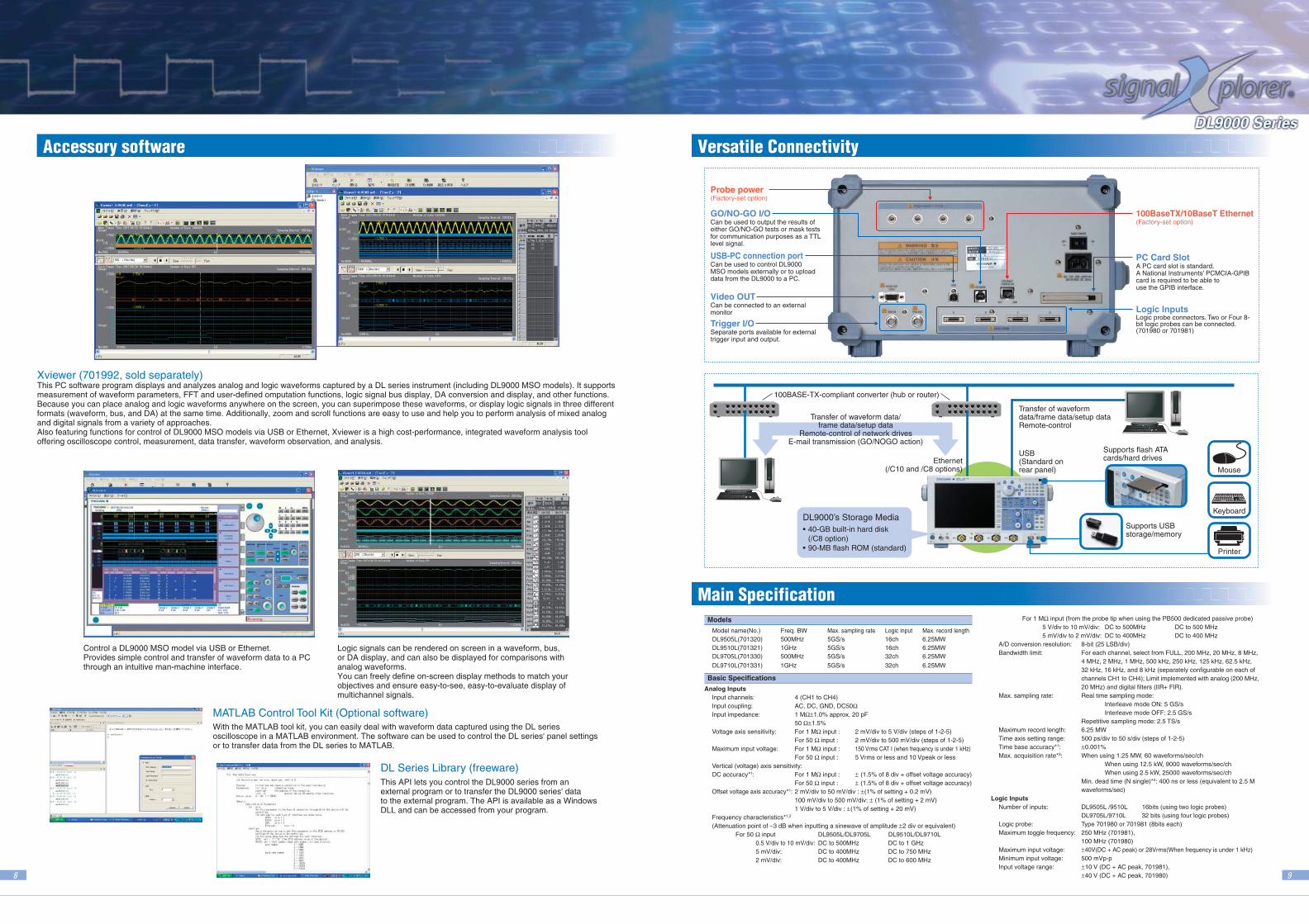
Control a DL9000 MSO model via USB or Ethernet.Provides simple control and transfer of waveform data to a PC through an intuitive man-machine interface.
Logic signals can be rendered on screen in a waveform, bus, or DA display, and can also be displayed for comparisons with analog waveforms. You can freely define on-screen display methods to match your objectives and ensure easy-to-see, easy-to-evaluate display of multichannel signals.
Xviewer (701992, sold separately) This PC software program displays and analyzes analog and logic waveforms captured by a DL series instrument (including DL9000 MSO models). It supports measurement of waveform parameters, FFT and user-defined omputation functions, logic signal bus display, DA conversion and display, and other functions. Because you can place analog and logic waveforms anywhere on the screen, you can superimpose these waveforms, or display logic signals in three different formats (waveform, bus, and DA) at the same time. Additionally, zoom and scroll functions are easy to use and help you to perform analysis of mixed analog and digital signals from a variety of approaches. Also featuring functions for control of DL9000 MSO models via USB or Ethernet, Xviewer is a high cost-performance, integrated waveform analysis tool offering oscilloscope control, measurement, data transfer, waveform observation, and analysis.
This API lets you control the DL9000 series from anexternal program or to transfer the DL9000 series' datato the external program. The API is available as a Windows DLL and can be accessed from your program.
DL Series Library (freeware)
With the MATLAB tool kit, you can easily deal with waveform data captured using the DL series oscilloscope in a MATLAB environment. The software can be used to control the DL series' panel settings or to transfer data from the DL series to MATLAB.
MATLAB Control Tool Kit (Optional software)
Accessory softwareAccessory software Versatile ConnectivityVersatile Connectivity
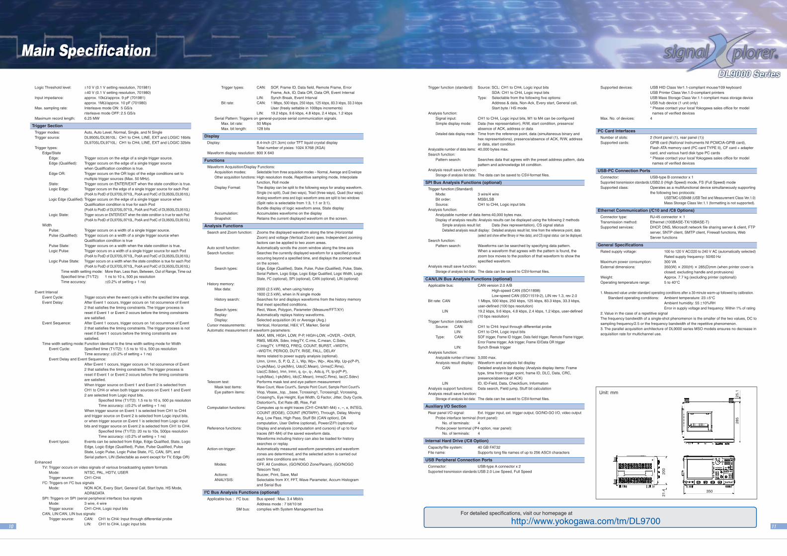
Can be used to output the results of either GO/NO-GO tests or mask tests for communication purposes as a TTL level signal.
GO/NO-GO I/O
(Factory-set option)Probe power
Separate ports available for external trigger input and output.
Trigger I/O
Can be used to control DL9000 MSO models externally or to upload data from the DL9000 to a PC.
USB-PC connection port
100BaseTX/10BaseT Ethernet(Factory-set option)
Can be connected to an external monitor
Video OUT
A PC card slot is standard. A National Instruments’ PCMCIA-GPIB card is required to be able to use the GPIB interface.
PC Card Slot
Logic probe connectors. Two or Four 8-bit logic probes can be connected. (701980 or 701981)
Logic Inputs
Models
Model name(No.) Freq. BW Max. sampling rate Logic input Max. record lengthDL9505L(701320) 500MHz 5GS/s 16ch 6.25MWDL9510L(701321) 1GHz 5GS/s 16ch 6.25MWDL9705L(701330) 500MHz 5GS/s 32ch 6.25MW
DL9710L(701331) 1GHz 5GS/s 32ch 6.25MW
Basic Specifications
Analog InputsInput channels: 4 (CH1 to CH4)Input coupling: AC, DC, GND, DC50ΩInput impedance: 1 MΩ±1.0% approx. 20 pF
50 Ω±1.5%Voltage axis sensitivity: For 1 MΩ input : 2 mV/div to 5 V/div (steps of 1-2-5)
For 50 Ω input : 2 mV/div to 500 mV/div (steps of 1-2-5)Maximum input voltage: For 1 MΩ input : 150 Vrms CAT I (when frequency is under 1 kHz)
For 50 Ω input : 5 Vrms or less and 10 Vpeak or lessVertical (voltage) axis sensitivity:DC accuracy*1: For 1 MΩ input : ± (1.5% of 8 div + offset voltage accuracy)
For 50 Ω input : ± (1.5% of 8 div + offset voltage accuracy)Offset voltage axis accuracy*1: 2 mV/div to 50 mV/div : ±(1% of setting + 0.2 mV)
100 mV/div to 500 mV/div: ± (1% of setting + 2 mV)1 V/div to 5 V/div : ±(1% of setting + 20 mV)
Frequency characteristics*1,2
(Attenuation point of –3 dB when inputting a sinewave of amplitude ±2 div or equivalent)For 50 Ω input DL9505L/DL9705L DL9510L/DL9710L
0.5 V/div to 10 mV/div: DC to 500MHz DC to 1 GHz5 mV/div: DC to 400MHz DC to 750 MHz2 mV/div: DC to 400MHz DC to 600 MHz
For 1 MΩ input (from the probe tip when using the PB500 dedicated passive probe)5 V/div to 10 mV/div: DC to 500MHz DC to 500 MHz5 mV/div to 2 mV/div: DC to 400MHz DC to 400 MHz
A/D conversion resolution: 8-bit (25 LSB/div)Bandwidth limit: For each channel, select from FULL, 200 MHz, 20 MHz, 8 MHz,
4 MHz, 2 MHz, 1 MHz, 500 kHz, 250 kHz, 125 kHz, 62.5 kHz,32 kHz, 16 kHz, and 8 kHz (separately configurable on each ofchannels CH1 to CH4); Limit implemented with analog (200 MHz,20 MHz) and digital filters (IIR+ FIR).
Max. sampling rate: Real time sampling mode:Interleave mode ON: 5 GS/sInterleave mode OFF: 2.5 GS/s
Repetitive sampling mode: 2.5 TS/sMaximum record length: 6.25 MWTime axis setting range: 500 ps/div to 50 s/div (steps of 1-2-5)Time base accuracy*1: ±0.001%Max. acquisition rate*3: When using 1.25 MW, 60 waveforms/sec/ch
When using 12.5 kW, 9000 waveforms/sec/chWhen using 2.5 kW, 25000 waveforms/sec/ch
Min. dead time (N single)*3: 400 ns or less (equivalent to 2.5 Mwaveforms/sec)
Logic InputsNumber of inputs: DL9505L /9510L 16bits (using two logic probes)
DL9705L/9710L 32 bits (using four logic probes)Logic probe: Type 701980 or 701981 (8bits each)Maximum toggle frequency: 250 MHz (701981),
100 MHz (701980)Maximum input voltage: ±40V(DC + AC peak) or 28Vrms(When frequency is under 1 kHz)Minimum input voltage: 500 mVp-pInput voltage range: ±10 V (DC + AC peak, 701981),
±40 V (DC + AC peak, 701980)
主な仕様
10 11
For detailed specifications, visit our homepage at
http://www.yokogawa.com/tm/DL9700
25.1
285
200
350
21.4
Unit: mm
Logic Threshold level: ±10 V (0.1 V setting resolution, 701981)±40 V (0.1 V setting resolution, 701980)
Input impedance: approx. 10kΩ/approx. 9 pF (701981)approx. 1MΩ/approx. 10 pF (701980)
Max. sampling rate: Interleave mode ON: 5 GS/snterleave mode OFF: 2.5 GS/s
Maximum record length: 6.25 MW
Trigger Section
Trigger modes: Auto, Auto Level, Normal, Single, and N SingleTrigger source: DL9505L/DL9510L: CH1 to CH4, LINE, EXT and LOGIC 16bits
DL9705L/DL9710L: CH1 to CH4, LINE, EXT and LOGIC 32bitsTrigger types:
Edge/StateEdge: Trigger occurs on the edge of a single trigger source.Edge (Qualified): Trigger occurs on the edge of a single trigger source
when Qualification condition is true.Edge OR: Trigger occurs on the OR logic of the edge conditions set to
multiple trigger sources (Max. 50 MHz).State: Trigger occurs on ENTER/EXIT when the state condition is true.Logic Edge: Trigger occurs on the edge of a single trigger source for each Pod
(PodA to PodD of DL9705L/9710L, PodA and PodC of DL9505L/DL9510L)Logic Edge (Qualified): Trigger occurs on the edge of a single trigger source when
Qualification condition is true for each Pod(PodA to PodD of DL9705L/9710L, PodA and PodC of DL9505L/DL9510L)
Logic State: Trigger occurs on ENTER/EXIT when the state condition is tr ue for each Pod(PodA to PodD of DL9705L/9710L, PodA and PodC of DL9505L/DL9510L)
WidthPulse: Trigger occurs on a width of a single trigger source.Pulse (Qualified): Trigger occurs on a width of a single trigger source when
Qualification condition is truePulse State: Trigger occurs on a width when the state condition is true.Logic Pulse: Trigger occurs on a width of a single trigger source for each Pod
(PodA to PodD of DL9705L/9710L, PodA and PodC of DL9505L/DL9510L)Logic Pulse State: Trigger occurs on a width when the state condition is true for each Pod
(PodA to PodD of DL9705L/9710L, PodA and PodC of DL9505L/DL9510L)Time width setting mode: More than, Less than, Between, Out of Range, Time outSpecified time (T1/T2): 1 ns to 10 s, 500 ps resolutionTime accuracy: ±(0.2% of setting + 1 ns)
Event IntervalEvent Cycle: Trigger occurs when the event cycle is within the specified time range.Event Delay: After Event 1 occurs, trigger occurs on 1st occurrence of Event
2 that satisfies the timing constraints. The trigger process isreset if Event 1 or Event 2 occurs before the timing constraintsare satisfied.
Event Sequence: After Event 1 occurs, trigger occurs on 1st occurrence of Event2 that satisfies the timing constraints. The trigger process is notreset if Event 1 occurs before the timing constraints aresatisfied.
Time width setting mode:Function identical to the time width setting mode for WidthEvent Cycle: Specified time (T1/T2): 1.5 ns to 10 s, 500 ps resolution
Time accuracy: ±(0.2% of setting + 1 ns)Event Delay and Event Sequence:
After Event 1 occurs, trigger occurs on 1st occurrence of Event2 that satisfies the timing constraints. The trigger process isreset if Event 1 or Event 2 occurs before the timing constraintsare satisfied.When trigger source on Event 1 and Event 2 is selected fromCH1 to CH4 or when both trigger sources on Event 1 and Event2 are selected from Logic input bits.
Specified time (T1/T2): 1.5 ns to 10 s, 500 ps resolutionTime accuracy: ±(0.2% of setting + 1 ns)
When trigger source on Event 1 is selected from CH1 to CH4and trigger source on Event 2 is selected from Logic input bits,or when trigger source on Event 1 is selected from Logic inputbits and trigger source on Event 2 is selected from CH1 to CH4.
Specified time (T1/T2): 20 ns to 10s, 500ps resolutionTime accuracy: ±(0.2% of setting + 1 ns)
Event types: Events can be selected from Edge, Edge Qualified, State, LogicEdge, Logic Edge (Qualified), Pulse, Pulse Qualified, PulseState, Logic Pulse, Logic Pulse State, I2C, CAN, SPI, andSerial pattern, LIN (Selectable as event except for TV, Edge OR)
EnhancedTV: Trigger occurs on video signals of various broadcasting system formats
Mode: NTSC, PAL, HDTV, USERTrigger source: CH1-CH4
I2C: Triggers on I2C bus signalsMode: NON ACK, Every Start, General Call, Start byte, HS Mode,
ADR&DATASPI: Triggers on SPI (serial peripheral interface) bus signals
Mode: 3 wire, 4 wireTrigger source: CH1-CH4, Logic input bits
CAN, LIN:CAN, LIN bus signals:Trigger source: CAN: CH1 to CH4: Input through differential probe
LIN: CH1 to CH4, Logic input bits
Trigger types: CAN: SOF, Frame ID, Data field, Remote Frame, ErrorFrame, Ack, ID, Data OR, Data OR, Event Internal
LIN: Synch Break, Event IntervalBit rate: CAN: 1 Mbps, 500 kbps, 250 kbps, 125 kbps, 83.3 kbps, 33.3 kbps
User (freely settable in 100bps increments)LIN: 19.2 kbps, 9.6 kbps, 4.8 kbps, 2.4 kbps, 1.2 kbps
Serial Pattern: Triggers on general-purpose serial communication signals.Max. bit rate: 50 MbpsMax. bit length: 128 bits
Display
Display: 8.4-inch (21.3cm) color TFT liquid crystal displayTotal number of pixies: 1024 X768 (XGA)
Waveform display resolution: 800 X 640
Functions
Waveform Acquisition/Display Functions:Acquisition modes: Selectable from three acquisition modes – Normal, Average and EnvelopeOther acquisition functions: High resolution mode, Repetitive sampling mode, Interpolate
function, Roll modeDisplay Format: The display can be split to the following ways for analog waveform.
Single (no split), Dual (two ways), Triad (three ways), Quad (four ways)Analog waveform area and logic waveform area are split to two windows(Split ratio is selectable from 1:3, 1:1 or 3:1).Bundle display of logic waveform area, State display
Accumulation: Accumulates waveforms on the displaySnapshot: Retains the current displayed waveform on the screen.
Analysis Functions
Search and Zoom function: Zooms the displayed waveform along the time (HorizontalZoom) and voltage (Vertical Zoom) axes. Independent zoomingfactors can be applied to two zoom areas.
Auto scroll function: Automatically scrolls the zoom window along the time axisSearch function: Searches the currently displayed waveform for a specified portion
occurring beyond a specified time, and displays the zoomed resulton the screen.
Search types: Edge, Edge (Qualified), State, Pulse, Pulse (Qualified), Pulse, State,Serial Pattern, Logic Edge, Logic Edge Qualified, Logic Width, LogicState, I2C (optional), SPI (optional), CAN (optional), LIN (optional)
History memory:Max data: 2000 (2.5 kW), when using history
1600 (2.5 kW), when in N single modeHistory search: Searches for and displays waveforms from the history memory
that meet specified conditions.Search types: Rect, Wave, Polygon, Parameter (Measure/FFT/XY)Replay: Automatically replays history waveforms.Display: Selected acquisition (#) or Average (Avg.)
Cursor measurements: Vertical, Horizontal, H&V, VT, Marker, SerialAutomatic measurement of waveform parameters:
MAX, MIN, HIGH, LOW, P-P, HIGH-LOW, +OVER, –OVER,RMS, MEAN, Sdev, IntegTY, C.rms, C.mean, C.Sdev,C.IntegTY, 1/FREQ, FREQ, COUNT, BURST, +WIDTH,–WIDTH, PERIOD, DUTY, RISE, FALL, DELAYItems related to power supply analysis (optional).Umn, Urmn, S, P, Q, Z, λ, Wp, Wp+, Wp-, Abs.Wp, Up-p(P-P),U+pk(Max), U-pk(Min), Udc(C.Mean), Urms(C.Rms),Uac(C.Sdev), Imn, Irmn, q, q+, q-, Ads.q, I2t, Ip-p(P-P),I+pk(Max), I-pk(Min), Idc(C.Mean), Irms(C.Rms), Iac(C.Sdev)
Telecom test: Performs mask test and eye pattern measurementMask test items: Wave Count, Wave Count%, Sample Point Count, Sample Point Count%Eye pattern items: Vtop, Vbase,_top, _base, Tcrossing1, Tcrossing2, Vcrossing,
Crossing%, Eye Height, Eye Width, Q Factor, Jitter, Duty Cycle,Distortion%, Ext Rate dB, Rise, Fall
Computation functions: Computes up to eight traces (CH1-CH4/M1-M4) +, –, x, INTEG,COUNT (EDGE), COUNT (ROTARY), Through, Delay, MovingAvg, Low Pass, High Pass, Stuff Bit (CAN option), DAcomputation, User Define (optional), Power/Z/I2t (optional)
Reference functions: Display and analysis (computation and cursors) of up to fourtraces (M1-M4) of the saved waveform data.Waveforms including history can also be loaded for historysearches or replay.
Action-on-trigger: Automatically measured waveform parameters and waveformzones are determined, and the selected action is carried outeach time conditions are met.
Modes: OFF, All Condition, (GO/NOGO Zone/Param), (GO/NOGOTelecom Test)
Actions: Buzzer, Print, Save, MailANALYSIS: Selectable from XY, FFT, Wave Parameter, Accum Histogram
and Serial Bus
I2C Bus Analysis Functions (optional)
Applicable bus : I2C bus: Bus speed : Max. 3.4 Mbit/sAddress mode : 7 bit/10 bit
SM bus: complies with System Management bus
Trigger function (standard): Source: SCL: CH1 to CH4, Logic input bitsSDA: CH1 to CH4, Logic input bits
Type: Selectable from the following five options:Address & data, Non-Ack, Every start, General call,Start byte / HS mode
Analysis function:Signal input: CH1 to CH4, Logic input bits, M1 to M4 can be configuredSimple display mode: Data (hex representation), R/W, start condition, presence/
absence of ACK, address or dataDetailed data display mode: Time from the reference point, data (simultaneous binary and
hex representations), presence/absence of ACK, R/W, addressor data, start condition
Analyzable number of data items: 40,000 bytes max.Search function:
Pattern search: Searches data that agrees with the preset address pattern, datapattern and acknowledge bit condition.
Analysis result save function:Storage of analysis list data: The data can be saved to CSV-format files.
SPI Bus Analysis Functions (optional)
Trigger function:(Standard)Mode: 3 wire/4 wireBit order: MSB/LSBSource: CH1 to CH4, Logic input bits
Analysis function:Analyzable number of data items:40,000 bytes max.Display of analysis results: Analysis results can be displayed using the following 2 methods
Simple analysis result list: Data (hex representation), CS signal statusDetailed analysis result display: Detailed analysis result list, time from the reference point, data
(select and show either Binary or Hex data), and CS signal status can be displayed.Search function:
Pattern search: Waveforms can be searched by specifying data pattern.When a waveform that agrees with the pattern is found, thezoom box moves to the position of that waveform to show thespecified waveform.
Analysis result save function:Storage of analysis list data: The data can be saved to CSV-format files.
CAN/LIN Bus Analysis Functions (optional)
Applicable bus: CAN version 2.0 A/BHigh-speed CAN (ISO11898)Low-speed CAN (ISO11519-2), LIN rev 1.3, rev 2.0
Bit rate: CAN 1 Mbps, 500 kbps, 250 kbps, 125 kbps, 83.3 kbps, 33.3 kbps,user-defined (100 bps resolution)
LIN 19.2 kbps, 9.6 kbps, 4.8 kbps, 2.4 kbps, 1.2 kbps, user-defined(10 bps resolution)
Trigger function (standard):Source: CAN: CH1 to CH4: Input through differential probe
LIN: CH1 to CH4, Logic input bitsType: CAN: SOF trigger, Frame ID trigger, Data field trigger, Remote Frame trigger,
Error Frame trigger, Ack trigger, Frame ID/Data OR triggerLIN: Synch Break trigger
Analysis function:Analyzable number of frames: 3,000 max.Analysis result display: Waveform and analysis list display
CAN Detailed analysis list display (Analysis display items: Frametype, time from trigger point, frame ID, DLC, Data, CRC,presence/absence of ACK)
LIN ID, ID-Field, Data, CheckSum, InformationAnalysis support functions: Data search, Field jump, Stuff bit calculationAnalysis result save function:
Storage of analysis list data: The data can be saved to CSV-format files.
Auxiliary I/O Section
Rear panel I/O signal: Ext. trigger input, ext. trigger output, GO/NO-GO I/O, video outputProbe interface terminal (front panel):
No. of terminals: 4Probe power terminal (/P4 option, rear panel):
No. of terminals: 4
Internal Hard Drive (/C8 Option)
Capacity/file system: 40 GB FAT32File name: Supports long file names of up to 256 ASCII characters
USB Peripheral Connection Ports
Connector: USB-type A connector x 2Supported transmission standards:USB 2.0 Low Speed, Full Speed
Supported devices: USB HID Class Ver1.1-compliant mouse/109 keyboardUSB Printer Class Ver.1.0-compliant printersUSB Mass Storage Class Ver.1.1-compliant mass storage deviceUSB hub device (1 unit only)* Please contact your local Yokogawa sales office for model names of verified devices
Max. No. of devices: 4
PC Card Interfaces
Number of slots: 2 (front panel (1), rear panel (1))Supported cards: GPIB card (National Instruments NI PCMCIA-GPIB card),
Flash ATA memory card (PC card TYPE II), CF card + adaptercard, and various hard disk type PC cards* Please contact your local Yokogawa sales office for model names of verified devices
USB-PC Connection Ports
Connector: USB-type B connector x 1Supported transmission standards:USB2.0 (High Speed) mode, FS (Full Speed) modeSupported class: Operates as a multifunctional device simultaneously supporting
the following two protocols:USBTMC-USB488 (USB Test and Measurement Class Ver.1.0)Mass Storage Class Ver.1.1 (formatting is not supported).
Ethernet Communication (/C10 and /C8 Options)
Connector type: RJ-45 connector 1Transmission method: Ethernet (100BASE-TX/10BASE-T)Supported services: DHCP, DNS, Microsoft network file sharing server & client, FTP
server, SNTP client, SMTP client, Firewall functions, WebServer functions
General Specifications
Rated supply voltage: 100 to 120 V AC/220 to 240 V AC (automatically selected)Rated supply frequency: 50/60 Hz
Maximum power consumption: 300 VAExternal dimensions: 350(W) 200(H) 285(D)mm (when printer cover is
closed; excluding handle and protrusions)Weight: Approx. 7.7 kg (excluding printer (optional))Operating temperature range: 5 to 40°C
1. Measured value under standard operating conditions after a 30-minute warm-up followed by calibration.Standard operating conditions: Ambient temperature: 23 ±5°C
Ambient humidity: 55 ±10%RHError in supply voltage and frequency: Within 1% of rating
2. Value in the case of a repetitive signalThe frequency bandwidth of a single-shot phenomenon is the smaller of the two values, DC tosampling frequency/2.5 or the frequency bandwidth of the repetitive phenomenon.3. The parallel acquisition architecture of DL9000 series MSO models ensures no decrease inacquisition rate for multichannel use.
32bitLogic
16bitLogic
4chAnalog
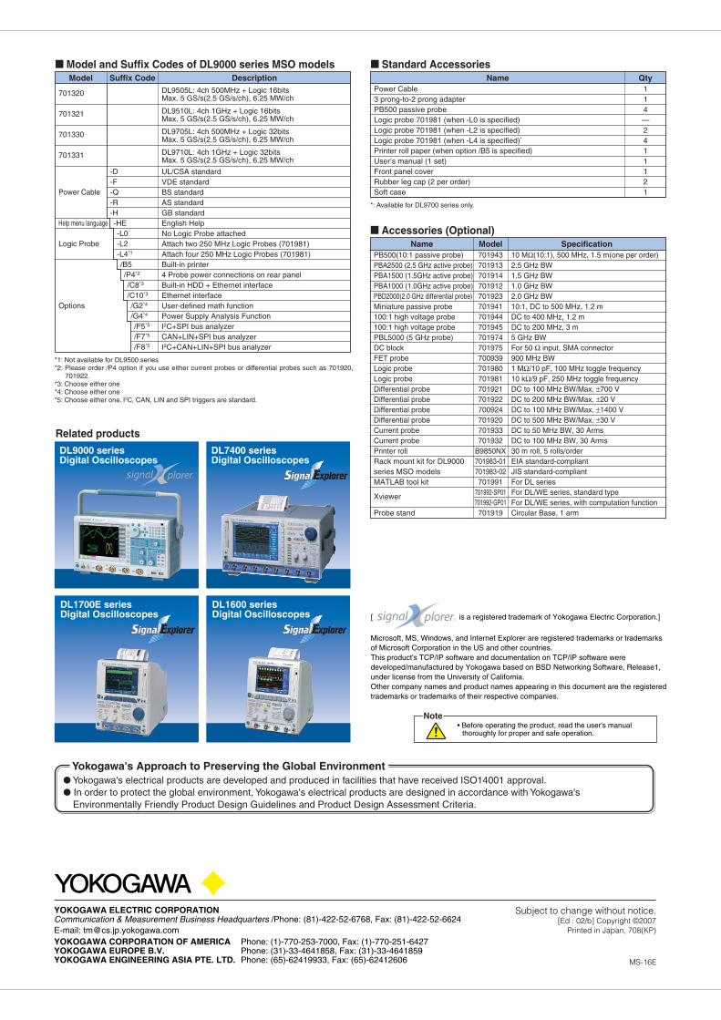
Accessories (Optional)
Standard Accessories
Power Cable3 prong-to-2 prong adapterPB500 passive probeLogic probe 701981 (when -L0 is specified)Logic probe 701981 (when -L2 is specified)Logic probe 701981 (when -L4 is specified)*
Printer roll paper (when option /B5 is specified)User’s manual (1 set)Front panel coverRubber leg cap (2 per order)Soft case
114—2411121
*1: Not available for DL9500 series*2: Please order /P4 option if you use either current probes or differential probes such as 701920,
701922.*3: Choose either one*4: Choose either one*5: Choose either one. I2C, CAN, LIN and SPI triggers are standard.
Model and Suffix Codes of DL9000 series MSO models
DL9505L: 4ch 500MHz + Logic 16bitsMax. 5 GS/s(2.5 GS/s/ch), 6.25 MW/ch
DL9510L: 4ch 1GHz + Logic 16bitsMax. 5 GS/s(2.5 GS/s/ch), 6.25 MW/ch
DL9705L: 4ch 500MHz + Logic 32bitsMax. 5 GS/s(2.5 GS/s/ch), 6.25 MW/ch
DL9710L: 4ch 1GHz + Logic 32bitsMax. 5 GS/s(2.5 GS/s/ch), 6.25 MW/ch
UL/CSA standardVDE standardBS standardAS standardGB standardEnglish HelpNo Logic Probe attachedAttach two 250 MHz Logic Probes (701981)Attach four 250 MHz Logic Probes (701981)Built-in printer4 Probe power connections on rear panelBuilt-in HDD + Ethernet interfaceEthernet interfaceUser-defined math functionPower Supply Analysis FunctionI2C+SPI bus analyzerCAN+LIN+SPI bus analyzerI2C+CAN+LIN+SPI bus analyzer
701320
701321
701330
701331
Power Cable
Help menu language
Logic Probe
Options
*: Available for DL9700 series only.
Model
Model
Suffix Code Description
Specification
Name
Name
Qty
-D-F-Q-R-H-HE-L0-L2-L4*1
/B5/P4*2
/C8*3
/C10*3
/G2*4
/G4*4
/F5*5
/F7*5
/F8*5
PB500(10:1 passive probe)PBA2500 (2.5 GHz active probe)PBA1500 (1.5GHz active probe)PBA1000 (1.0GHz active probe)PBD2000(2.0 GHz differential probe)Miniature passive probe100:1 high voltage probe100:1 high voltage probePBL5000 (5 GHz probe)DC blockFET probeLogic probeLogic probeDifferential probeDifferential probeDifferential probeDifferential probeCurrent probeCurrent probePrinter rollRack mount kit for DL9000 series MSO modelsMATLAB tool kit
Xviewer
Probe stand
10 MΩ(10:1), 500 MHz, 1.5 m(one per order)2.5 GHz BW1.5 GHz BW1.0 GHz BW2.0 GHz BW10:1, DC to 500 MHz, 1.2 mDC to 400 MHz, 1.2 mDC to 200 MHz, 3 m5 GHz BWFor 50 Ω input, SMA connector900 MHz BW1 MΩ/10 pF, 100 MHz toggle frequency10 kΩ/9 pF, 250 MHz toggle frequencyDC to 100 MHz BW/Max. ±700 VDC to 200 MHz BW/Max. ±20 VDC to 100 MHz BW/Max. ±1400 VDC to 500 MHz BW/Max. ±30 VDC to 50 MHz BW, 30 ArmsDC to 100 MHz BW, 30 Arms30 m roll, 5 rolls/orderEIA standard-compliantJIS standard-compliantFor DL seriesFor DL/WE series, standard typeFor DL/WE series, with computation functionCircular Base, 1 arm
701943701913701914701912701923701941701944701945701974701975700939701980701981701921701922700924701920701933701932
B9850NX701983-01701983-02701991
701992-SP01701992-GP01701919
Subject to change without notice.[Ed : 02/b] Copyright ©2007
Printed in Japan, 708(KP)
YOKOGAWA ELECTRIC CORPORATIONCommunication & Measurement Business Headquarters /Phone: (81)-422-52-6768, Fax: (81)-422-52-6624E-mail: [email protected] CORPORATION OF AMERICA Phone: (1)-770-253-7000, Fax: (1)-770-251-6427YOKOGAWA EUROPE B.V. Phone: (31)-33-4641858, Fax: (31)-33-4641859YOKOGAWA ENGINEERING ASIA PTE. LTD. Phone: (65)-62419933, Fax: (65)-62412606 MS-16E
Related products
DL9000 seriesDigital Oscilloscopes
DL1600 seriesDigital Oscilloscopes
DL1700E seriesDigital Oscilloscopes
DL7400 seriesDigital Oscilloscopes
• Before operating the product, read the user's manual thoroughly for proper and safe operation.
Note
Microsoft, MS, Windows, and Internet Explorer are registered trademarks or trademarks of Microsoft Corporation in the US and other countries.This product's TCP/IP software and documentation on TCP/IP software weredeveloped/manufactured by Yokogawa based on BSD Networking Software, Release1, under license from the University of California.Other company names and product names appearing in this document are the registered trademarks or trademarks of their respective companies.
[ is a registered trademark of Yokogawa Electric Corporation.]
Yokogawa's electrical products are developed and produced in facilities that have received ISO14001 approval. In order to protect the global environment, Yokogawa's electrical products are designed in accordance with Yokogawa's
Environmentally Friendly Product Design Guidelines and Product Design Assessment Criteria.
Yokogawa's Approach to Preserving the Global Environment


![MSO/DS2000A Series Digital Oscilloscope · MSO/DS2202A/2202A-S: 1.8 ns MSO/DS2102A/2102A-S: 3.5 ns MSO/DS2072A/2072A-S: 5 ns DC Gain Accuracy[3] ±2% full scale DC Offset Accuracy](https://img.pdfslide.us/doc/110x75/6000e6c7dde05f20c43f2bd6/msods2000a-series-digital-oscilloscope-msods2202a2202a-s-18-ns-msods2102a2102a-s.jpg)