Embed Size (px)
Citation preview
Copyright © 2012–2015 Pico Technology Limited. All rights reserved.
User's Guide
ps3000d.en r2
D and D MSO model oscilloscopes
PicoScope® 3000 Series

IPicoScope 3000D Series Oscilloscope & MSO User's Guide
Copyright © 2012–2015 Pico Technology Limited. All rights reserved. ps3000d.en r2
Contents1 Introduction ................................................................................................................................ 1
1 Safety information .............................................................................................................................. 3
1 Symbols .................................................................................................................................. 4
2 Maximum input ranges ............................................................................................................ 5
3 Grounding .............................................................................................................................. 6
4 External connections ............................................................................................................... 6
5 Environment ........................................................................................................................... 7
6 Care of the instrument ............................................................................................................ 7
2 Conformance ...................................................................................................................................... 8
1 FCC notice .............................................................................................................................. 8
2 CE notice ................................................................................................................................ 8
3 Software license conditions ................................................................................................................. 9
4 Trademarks ........................................................................................................................................ 9
5 Warranty ......................................................................................................................................... 10
2 Product information ................................................................................................................. 11
1 Connector diagrams .......................................................................................................................... 11
1 2-channel model connector diagram ....................................................................................... 12
2 4-channel model connector diagram ....................................................................................... 13
3 2-channel MSO model connector diagram .............................................................................. 14
4 4-channel MSO model connector diagram .............................................................................. 15
5 Digital inputs on MSO models ................................................................................................ 16
2 Connectivity, power and installation .................................................................................................. 17
3 Minimum system requirements .......................................................................................................... 19
4 Pack contents ................................................................................................................................... 20
5 Compensating probes ....................................................................................................................... 21
3 Glossary .................................................................................................................................... 22
Index ........................................................................................................................................... 25

PicoScope 3000D Series Oscilloscope & MSO User's Guide 1
Copyright © 2012–2015 Pico Technology Limited. All rights reserved. ps3000d.en r2
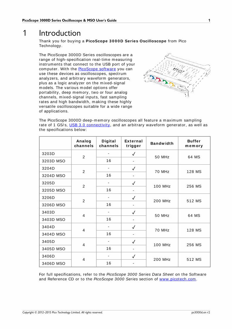
1 IntroductionThank you for buying a PicoScope 3000D Series Oscilloscope from PicoTechnology.
The PicoScope 3000D Series oscilloscopes are arange of high-specification real-time measuringinstruments that connect to the USB port of yourcomputer. With the PicoScope software you canuse these devices as oscilloscopes, spectrumanalyzers, and arbitrary waveform generators,plus as a logic analyzer on the mixed-signalmodels. The various model options offerportability, deep memory, two or four analogchannels, mixed-signal inputs, fast samplingrates and high bandwidth, making these highlyversatile oscilloscopes suitable for a wide rangeof applications.
The PicoScope 3000D deep-memory oscilloscopes all feature a maximum samplingrate of 1 GS/s, USB 3.0 connectivity, and an arbitrary waveform generator, as well asthe specifications below:
Analogchannels
Digitalchannels
Externaltrigger
BandwidthBuffer
memory
3203D2
- 50 MHz 64 MS
3203D MSO 16 -
3204D2
- 70 MHz 128 MS
3204D MSO 16 -
3205D2
- 100 MHz 256 MS
3205D MSO 16 -
3206D2
- 200 MHz 512 MS
3206D MSO 16 -
3403D4
- 50 MHz 64 MS
3403D MSO 16 -
3404D4
- 70 MHz 128 MS
3404D MSO 16 -
3405D4
- 100 MHz 256 MS
3405D MSO 16 -
3406D4
- 200 MHz 512 MS
3406D MSO 16 -
For full specifications, refer to the PicoScope 3000 Series Data Sheet on the Softwareand Reference CD or to the PicoScope 3000 Series section of www.picotech.com.
Introduction2
Copyright © 2012–2015 Pico Technology Limited. All rights reserved.ps3000d.en r2
Some of the benefits provided by the PicoScope 3000D Series oscilloscopes are:
Portability. Take the unit with you and simply plug it in to any Windows PC.(Linux and Mac OS X are also supported in the Beta software).
Performance. Up to 200 MHz bandwidth, 512 MS buffer, and a 1 GS/s samplingrate.
Mixed signal capability. Display analog and digital signals on the same timebasewith the MSO models.
Flexibility. Use the device as an oscilloscope, spectrum analyzer, signal generator,or high-speed data acquisition interface.
Programmability. The PicoScope 3000A SDK lets you write your own programs,in your chosen programming language, to control all of the features of the scope.Using the API functions, you can develop your own programs to collect and analyzedata from the oscilloscope. Refer to the PicoScope 3000 Series (A API)Programmer's Guide for more information.
Long-term support. Software upgrades are available to download fromwww.picotech.com. You can also call our technical specialists for support. Theseservices are available free of charge for the lifetime of the product.
Value for money. You don't have to pay twice for features already available onyour PC, as the PicoScope 3000 Series oscilloscope contains the specializedhardware you need and nothing more.
Convenience. The software makes full use of the display, disk storage, userinterface, and networking built into your PC using a fast USB connection.
Five-year warranty. Your oscilloscope is covered against manufacturing faults forfive years from the day of purchase. We don't charge a penny extra for this.
PicoScope 3000D Series Oscilloscope & MSO User's Guide 3
Copyright © 2012–2015 Pico Technology Limited. All rights reserved. ps3000d.en r2
1.1 Safety informationTo prevent possible electrical shock, fire, personal injury, or damage to the product,carefully read this safety information before attempting to install or use the product.In addition, follow all generally accepted safety practices and procedures for workingwith and near electricity.
The product has been designed and tested in accordance with the European standardpublication EN 61010-1: 2010 and left the factory in a safe condition.
The following safety descriptions are found throughout this guide:
A WARNING identifies conditions or practices that could result in injury or death.
A CAUTION identifies conditions or practices that could result in damage to theproduct or equipment to which it is connected.
Each of these safety instructions applies to all of the PicoScope 3000 Seriesoscilloscopes covered by this User's Guide unless otherwise specified.
Introduction4
Copyright © 2012–2015 Pico Technology Limited. All rights reserved.ps3000d.en r2
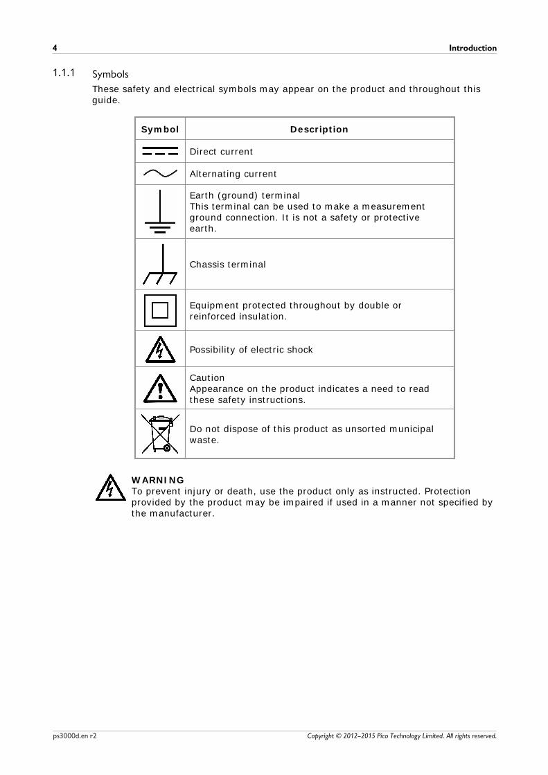
1.1.1 Symbols
These safety and electrical symbols may appear on the product and throughout thisguide.
Symbol Description
Direct current
Alternating current
Earth (ground) terminalThis terminal can be used to make a measurementground connection. It is not a safety or protectiveearth.
Chassis terminal
Equipment protected throughout by double orreinforced insulation.
Possibility of electric shock
CautionAppearance on the product indicates a need to readthese safety instructions.
Do not dispose of this product as unsorted municipalwaste.
WARNINGTo prevent injury or death, use the product only as instructed. Protectionprovided by the product may be impaired if used in a manner not specified bythe manufacturer.
PicoScope 3000D Series Oscilloscope & MSO User's Guide 5
Copyright © 2012–2015 Pico Technology Limited. All rights reserved. ps3000d.en r2
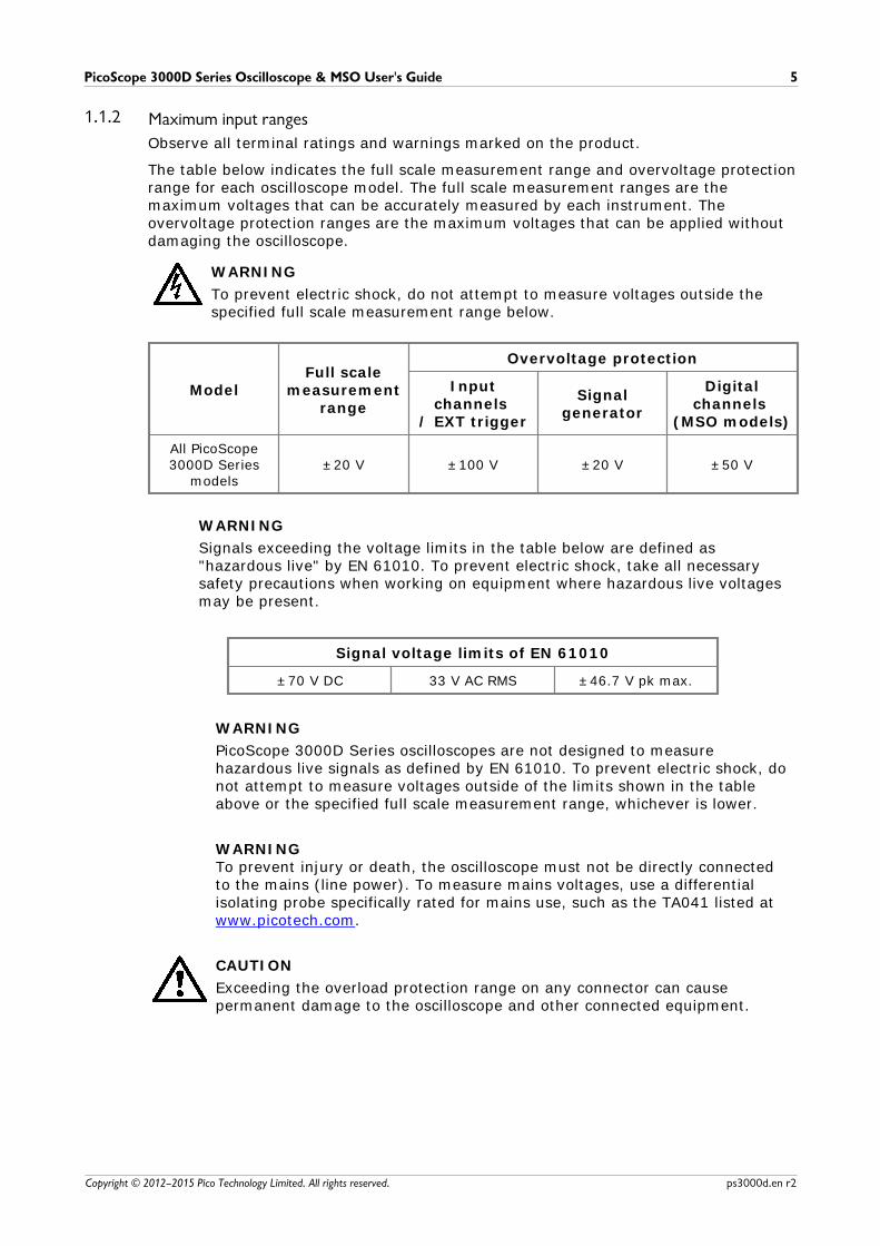
1.1.2 Maximum input ranges
Observe all terminal ratings and warnings marked on the product.
The table below indicates the full scale measurement range and overvoltage protectionrange for each oscilloscope model. The full scale measurement ranges are themaximum voltages that can be accurately measured by each instrument. Theovervoltage protection ranges are the maximum voltages that can be applied withoutdamaging the oscilloscope.
WARNING
To prevent electric shock, do not attempt to measure voltages outside thespecified full scale measurement range below.
ModelFull scale
measurementrange
Overvoltage protection
Inputchannels
/ EXT trigger
Signalgenerator
Digitalchannels
(MSO models)
All PicoScope3000D Series
models±20 V ±100 V ±20 V ±50 V
WARNING
Signals exceeding the voltage limits in the table below are defined as"hazardous live" by EN 61010. To prevent electric shock, take all necessarysafety precautions when working on equipment where hazardous live voltagesmay be present.
Signal voltage limits of EN 61010
±70 V DC 33 V AC RMS ±46.7 V pk max.
WARNING
PicoScope 3000D Series oscilloscopes are not designed to measurehazardous live signals as defined by EN 61010. To prevent electric shock, donot attempt to measure voltages outside of the limits shown in the tableabove or the specified full scale measurement range, whichever is lower.
WARNINGTo prevent injury or death, the oscilloscope must not be directly connectedto the mains (line power). To measure mains voltages, use a differentialisolating probe specifically rated for mains use, such as the TA041 listed at www.picotech.com.
CAUTION
Exceeding the overload protection range on any connector can causepermanent damage to the oscilloscope and other connected equipment.
Introduction6
Copyright © 2012–2015 Pico Technology Limited. All rights reserved.ps3000d.en r2
1.1.3 Grounding
WARNING
The oscilloscope's ground connection through the USB cable is formeasurement purposes only. The oscilloscope does not have a protectivesafety ground.
WARNING
Never connect the ground input (chassis) to any electrical power source. Toprevent personal injury or death, use a voltmeter to check that there is nosignificant AC or DC voltage between the oscilloscope ground and the pointto which you intend to connect it.
CAUTION
Applying a voltage to the ground input is likely to cause permanent damageto the oscilloscope, the attached computer, and other equipment.
CAUTION
To prevent measurement errors caused by poor grounding, always use thehigh-quality USB cable supplied with the oscilloscope.
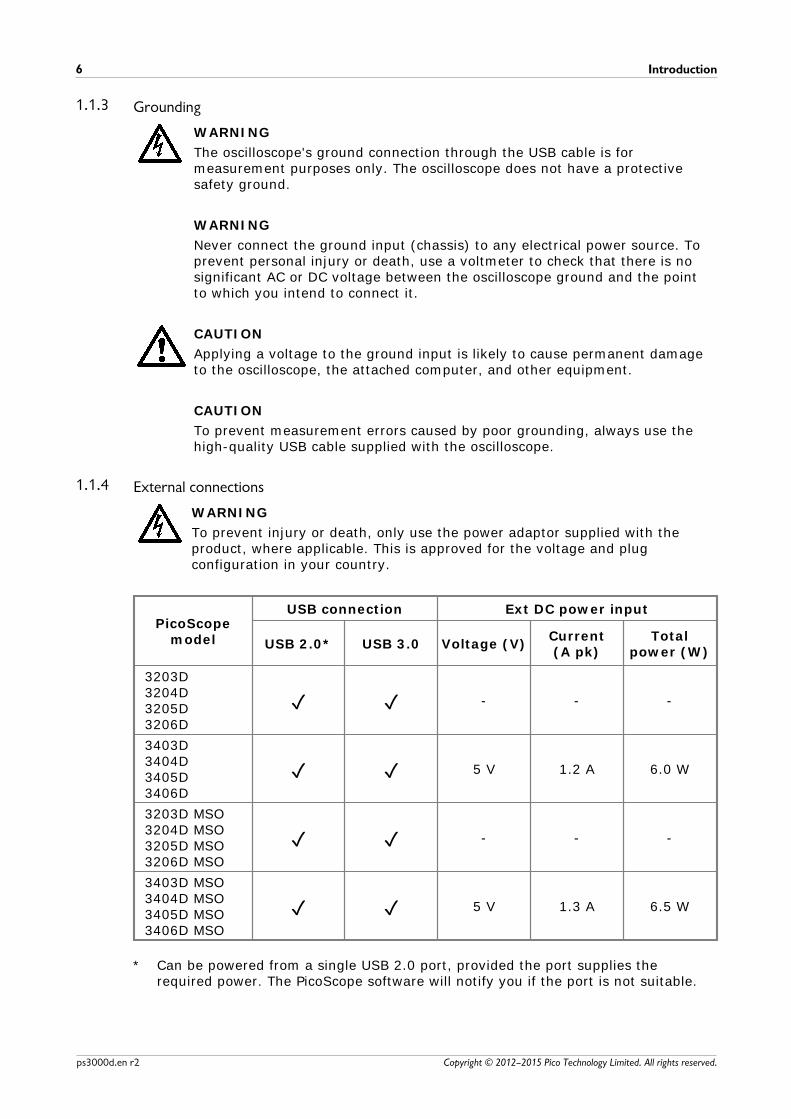
1.1.4 External connections
WARNING
To prevent injury or death, only use the power adaptor supplied with theproduct, where applicable. This is approved for the voltage and plugconfiguration in your country.
PicoScopemodel
USB connection Ext DC power input
USB 2.0* USB 3.0 Voltage (V)Current(A pk)
Totalpower (W)
3203D3204D3205D3206D
- - -
3403D3404D3405D3406D
5 V 1.2 A 6.0 W
3203D MSO3204D MSO3205D MSO3206D MSO
- - -
3403D MSO3404D MSO3405D MSO3406D MSO
5 V 1.3 A 6.5 W
* Can be powered from a single USB 2.0 port, provided the port supplies therequired power. The PicoScope software will notify you if the port is not suitable.
PicoScope 3000D Series Oscilloscope & MSO User's Guide 7
Copyright © 2012–2015 Pico Technology Limited. All rights reserved. ps3000d.en r2
1.1.5 Environment
WARNING
To prevent injury or death, do not use in wet or damp conditions, or nearexplosive gas or vapor.
CAUTION
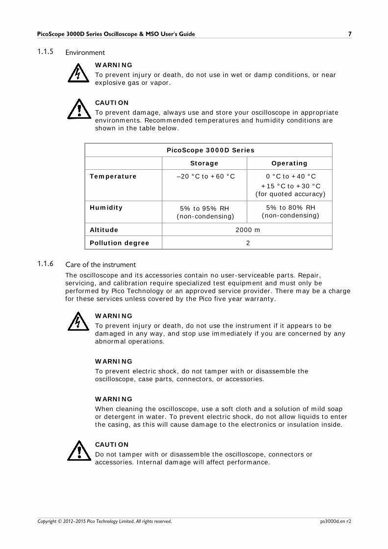
To prevent damage, always use and store your oscilloscope in appropriateenvironments. Recommended temperatures and humidity conditions areshown in the table below.
PicoScope 3000D Series
Storage Operating
Temperature –20 °C to +60 °C 0 °C to +40 °C
+15 °C to +30 °C(for quoted accuracy)
Humidity 5% to 95% RH (non-condensing)
5% to 80% RH(non-condensing)
Altitude 2000 m
Pollution degree 2
1.1.6 Care of the instrument
The oscilloscope and its accessories contain no user-serviceable parts. Repair,servicing, and calibration require specialized test equipment and must only beperformed by Pico Technology or an approved service provider. There may be a chargefor these services unless covered by the Pico five year warranty.
WARNING
To prevent injury or death, do not use the instrument if it appears to bedamaged in any way, and stop use immediately if you are concerned by anyabnormal operations.
WARNING
To prevent electric shock, do not tamper with or disassemble theoscilloscope, case parts, connectors, or accessories.
WARNING
When cleaning the oscilloscope, use a soft cloth and a solution of mild soapor detergent in water. To prevent electric shock, do not allow liquids to enterthe casing, as this will cause damage to the electronics or insulation inside.
CAUTION
Do not tamper with or disassemble the oscilloscope, connectors oraccessories. Internal damage will affect performance.
Introduction8
Copyright © 2012–2015 Pico Technology Limited. All rights reserved.ps3000d.en r2
1.2 Conformance
1.2.1 FCC notice
This equipment has been tested and found to comply with the limits for a Class Adigital device, pursuant to Part 15 of the FCC Rules. These limits are designed toprovide reasonable protection against harmful interference when the equipment isoperated in a commercial environment. This equipment generates, uses, and canradiate radio frequency energy and, if not installed and used in accordance with theinstruction manual, may cause harmful interference to radio communications.Operation of this equipment in a residential area is likely to cause harmful interferencein which case the user will be required to correct the interference at his or her ownexpense.
For safety and maintenance information see section 1.1.
1.2.2 CE notice
This product meets the intent of the EMC directive 2004/108/EC and has beentested to EN61326-1:2006 Class A Emissions and Basic Immunity.
The product also meets the intent of the Low Voltage Directive and has beendesigned to meet the BS EN 61010-1:2010 (safety requirements for electricalequipment for measurement, control, and laboratory use) standard.
PicoScope 3000D Series Oscilloscope & MSO User's Guide 9
Copyright © 2012–2015 Pico Technology Limited. All rights reserved. ps3000d.en r2
1.3 Software license conditionsThe software supplied with this product is licensed, not sold. Pico Technology Limitedgrants a license to the person who installs this software, subject to the conditionslisted below:
Access. The licensee agrees to allow access to this software only to persons who havebeen informed of these conditions and agree to abide by them.
Usage. The software in this release is for use only with Pico Technology products orwith data collected using Pico Technology products.
Copyright. Pico Technology Limited claims the copyright of, and retains the rights to,all material (software, documents etc.) contained in this release. You may copy anddistribute the PicoScope and PicoLog software and drivers with no modifications,additions or omissions. You may copy and modify the SDK example programs.
Liability. Pico Technology and its agents shall not be liable for any loss, damage orinjury, howsoever caused, related to the use of Pico Technology equipment orsoftware, unless excluded by statute.
Fitness for purpose. Because no two applications are the same, Pico Technologycannot guarantee that its equipment or software is suitable for a given application. Itis your responsibility, therefore, to ensure that the product is suitable for yourapplication.
Mission-critical applications. This software is intended for use on a computer thatmay be running other software products. For this reason, one of the conditions of thelicense is that it excludes usage in mission-critical applications such as life-supportsystems.
Viruses. This software was continuously monitored for viruses during production, butyou are responsible for virus-checking the software once it is installed.
Support. If you are dissatisfied with the performance of this software, please contactour technical support staff, who will try to fix the problem within a reasonable time. Ifyou are still dissatisfied, please return the product and software to your supplier within14 days of purchase for a full refund.
Upgrades. We provide upgrades, free of charge, from www.picotech.com. We reservethe right to charge for updates or replacements sent out on physical media.
1.4 TrademarksWindows is a registered trademark or trademark of Microsoft Corporation, registeredin the U.S. and other countries.
Linux is the registered trademark of Linus Torvalds, registered in the U.S. and othercountries.
Mac and OS X are trademarks of Apple Inc., registered in the U.S. and othercountries.
Pico Technology Limited and PicoScope are trademarks of Pico Technology Limited,registered in the United Kingdom and other countries.
PicoScope and Pico Technology are registered in the U.S. Patent and TrademarkOffice.

Introduction10
Copyright © 2012–2015 Pico Technology Limited. All rights reserved.ps3000d.en r2
1.5 WarrantyPico Technology warrants upon delivery, and for a period of 5 years unless otherwisestated from the date of delivery, that the Goods will be free from defects in materialand workmanship.
Pico Technology shall not be liable for a breach of the warranty if the defect has beencaused by fair wear and tear, wilful damage, negligence, abnormal working conditionsor failure to follow Pico Technology's spoken or written advice on the storage,installation, commissioning, use or maintenance of the Goods or (if no advice has beengiven) good trade practice; or if the Customer alters or repairs such Goods without thewritten consent of Pico Technology.
PicoScope 3000D Series Oscilloscope & MSO User's Guide 11
Copyright © 2012–2015 Pico Technology Limited. All rights reserved. ps3000d.en r2
2 Product information2.1 Connector diagrams
Standard oscilloscope connectorsThe analog input channels have standard BNC connectors and standard inputimpedances. They are therefore compatible with most oscilloscope probes includingx10 and switched x1/x10 variants. For optimum performance, always use the probessupplied with your PicoScope.
Arbitrary waveform generator outputThe built-in arbitrary waveform generator (AWG) can generate a waveform of almostany shape. The generated waveform can be injected into the device you wish to testand then analyzed as it progresses through the device to confirm correct operation, orto highlight a fault.
· If you are using the PicoScope 6 software, refer to the PicoScope 6 User's Guide forinformation on how to configure the arbitrary waveform generator.
· If you are writing your own software, refer to the PicoScope 3000 Series (A API)Programmer's Guide.
Digital inputs for mixed-signal oscilloscopes (D MSO models only)Alongside the analog channels, the mixed-signal 3000D MSO Series oscilloscopes alsofeature 16 digital inputs. The PicoScope software allows you to view both digital andanalog signals simultaneously. Your digital inputs are easily manageable, and can bereordered, grouped, and renamed.
Features such as triggering and serial decoding can also be used on the digitalchannels.
See Digital inputs for PicoScope 3000D Series MSO models for more information.
External trigger (EXT) input (D models only)The EXT input can be used as a trigger source. Select it from the Trigger menu in thePicoScope software, or by using a function call if you are writing your own software.
The EXT input uses dedicated circuitry, in combination with a software-configurablethreshold, to detect a trigger signal. This leaves the analog channels free for viewingsignals. The input characteristics of the EXT input are matched to a scope channel sothat the supplied, compensated probes can be used with the EXT input to give highvertical accuracy.
Where trigger timing accuracy is critical, we recommend using one of the main inputchannels as the trigger source. These channels use accurate digital triggering (to onesample period) and have a vertical resolution of 1 LSB.
USB portAll models have a SuperSpeed USB 3.0 port for connection to a PC. See Connectivity,power and installation for more information.
Earth terminalExternal noise may sometimes interfere with your measurements if the PicoScope isused with a computer which does not have a ground connection. If this is the case,connect the earth terminal to an external ground point (for example, on the systemyou are testing) to provide a ground reference for the oscilloscope.
Product information12
Copyright © 2012–2015 Pico Technology Limited. All rights reserved.ps3000d.en r2
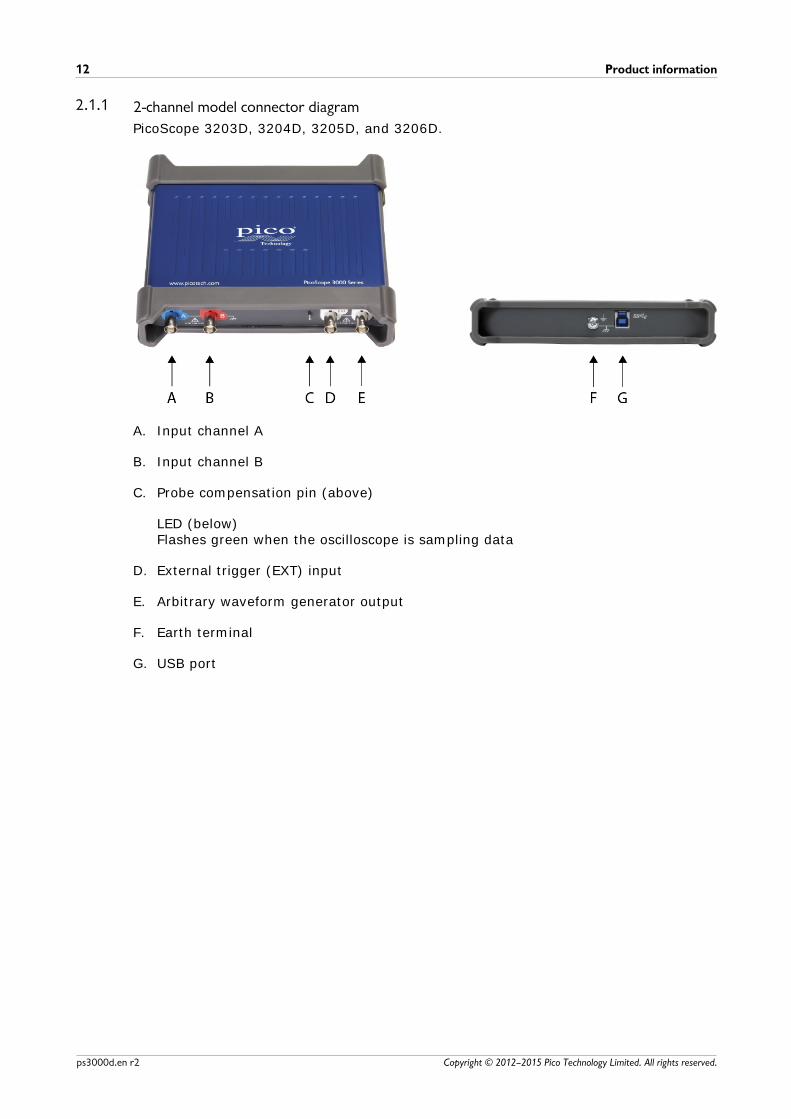
2.1.1 2-channel model connector diagram
PicoScope 3203D, 3204D, 3205D, and 3206D.
A. Input channel A
B. Input channel B
C. Probe compensation pin (above)
LED (below)Flashes green when the oscilloscope is sampling data
D. External trigger (EXT) input
E. Arbitrary waveform generator output
F. Earth terminal
G. USB port

PicoScope 3000D Series Oscilloscope & MSO User's Guide 13
Copyright © 2012–2015 Pico Technology Limited. All rights reserved. ps3000d.en r2
2.1.2 4-channel model connector diagram
PicoScope 3403D, 3404D, 3405D, and 3406D.
A. Input channel A
B. Input channel B
C. Input channel C
D. Input channel D
E. Probe compensation pin (above)
LED (below)Flashes green when the oscilloscope is sampling data
F. External trigger (EXT) input
G. Arbitrary waveform generator output
H. Earth terminal
I. USB port
J. DC power input
Product information14
Copyright © 2012–2015 Pico Technology Limited. All rights reserved.ps3000d.en r2
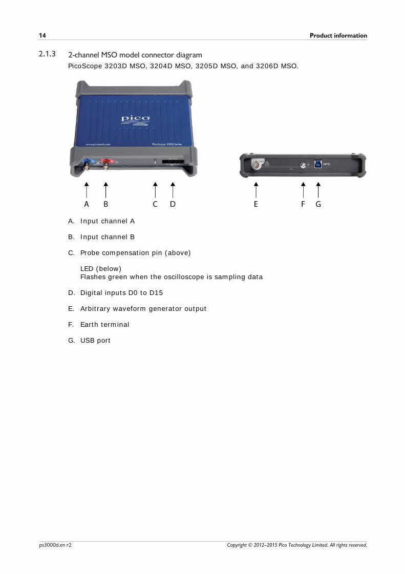
2.1.3 2-channel MSO model connector diagram
PicoScope 3203D MSO, 3204D MSO, 3205D MSO, and 3206D MSO.
A. Input channel A
B. Input channel B
C. Probe compensation pin (above)
LED (below)Flashes green when the oscilloscope is sampling data
D. Digital inputs D0 to D15
E. Arbitrary waveform generator output
F. Earth terminal
G. USB port
PicoScope 3000D Series Oscilloscope & MSO User's Guide 15
Copyright © 2012–2015 Pico Technology Limited. All rights reserved. ps3000d.en r2
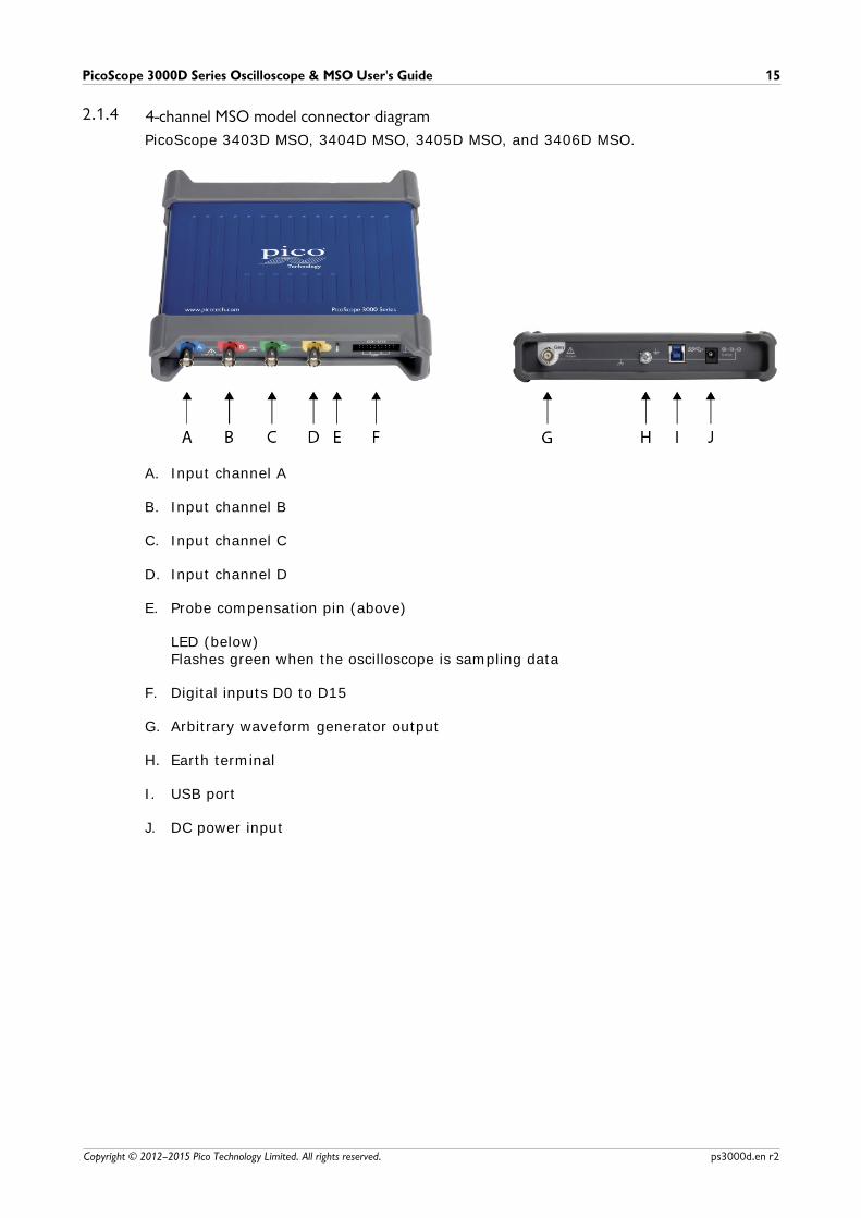
2.1.4 4-channel MSO model connector diagram
PicoScope 3403D MSO, 3404D MSO, 3405D MSO, and 3406D MSO.
A. Input channel A
B. Input channel B
C. Input channel C
D. Input channel D
E. Probe compensation pin (above)
LED (below)Flashes green when the oscilloscope is sampling data
F. Digital inputs D0 to D15
G. Arbitrary waveform generator output
H. Earth terminal
I. USB port
J. DC power input
Product information16
Copyright © 2012–2015 Pico Technology Limited. All rights reserved.ps3000d.en r2
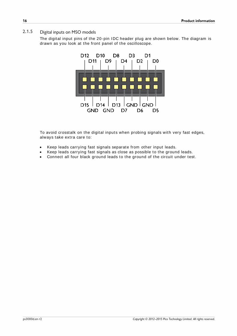
2.1.5 Digital inputs on MSO models
The digital input pins of the 20-pin IDC header plug are shown below. The diagram isdrawn as you look at the front panel of the oscilloscope.
To avoid crosstalk on the digital inputs when probing signals with very fast edges,always take extra care to:
· Keep leads carrying fast signals separate from other input leads.· Keep leads carrying fast signals as close as possible to the ground leads.· Connect all four black ground leads to the ground of the circuit under test.
PicoScope 3000D Series Oscilloscope & MSO User's Guide 17
Copyright © 2012–2015 Pico Technology Limited. All rights reserved. ps3000d.en r2
2.2 Connectivity, power and installation1. PicoScope software installation
Before setting up your PicoScope 3000 Series oscilloscope, it is recommended that youfirst install the PicoScope 6 software by following the instructions in the supplied QuickStart Guide.
There are different connectivity and power supply options for each oscilloscope modeldepending on its specifications.
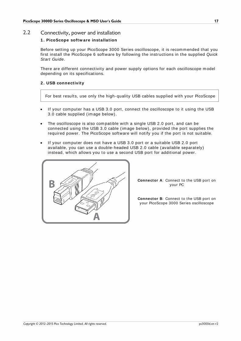
2. USB connectivity
For best results, use only the high-quality USB cables supplied with your PicoScope
· If your computer has a USB 3.0 port, connect the oscilloscope to it using the USB3.0 cable supplied (image below).
· The oscilloscope is also compatible with a single USB 2.0 port, and can beconnected using the USB 3.0 cable (image below), provided the port supplies therequired power. The PicoScope software will notify you if the port is not suitable.
· If your computer does not have a USB 3.0 port or a suitable USB 2.0 portavailable, you can use a double-headed USB 2.0 cable (available separately)instead, which allows you to use a second USB port for additional power.
Connector A: Connect to the USB port onyour PC
Connector B: Connect to the USB port onyour PicoScope 3000 Series oscilloscope
Product information18
Copyright © 2012–2015 Pico Technology Limited. All rights reserved.ps3000d.en r2
3. Oscilloscope installation
Once you have connected your oscilloscope to a PC using the appropriate USB cable,Windows will install the device. You will see different alerts depending on youroperating system. There is no need to reinsert the software CD.
· Windows XPA New Hardware Found wizard will be displayed. Simply click Next to run throughthe installation. If a Windows Logo Testing warning is displayed, click ContinueAnyway.
· Windows Vista, Windows 7, Windows 8 and Windows 10The process is automatic. An Installing device driver software message will bedisplayed during the installation.
Note: If you move your oscilloscope to a different USB port at any point theinstallation process will be repeated.
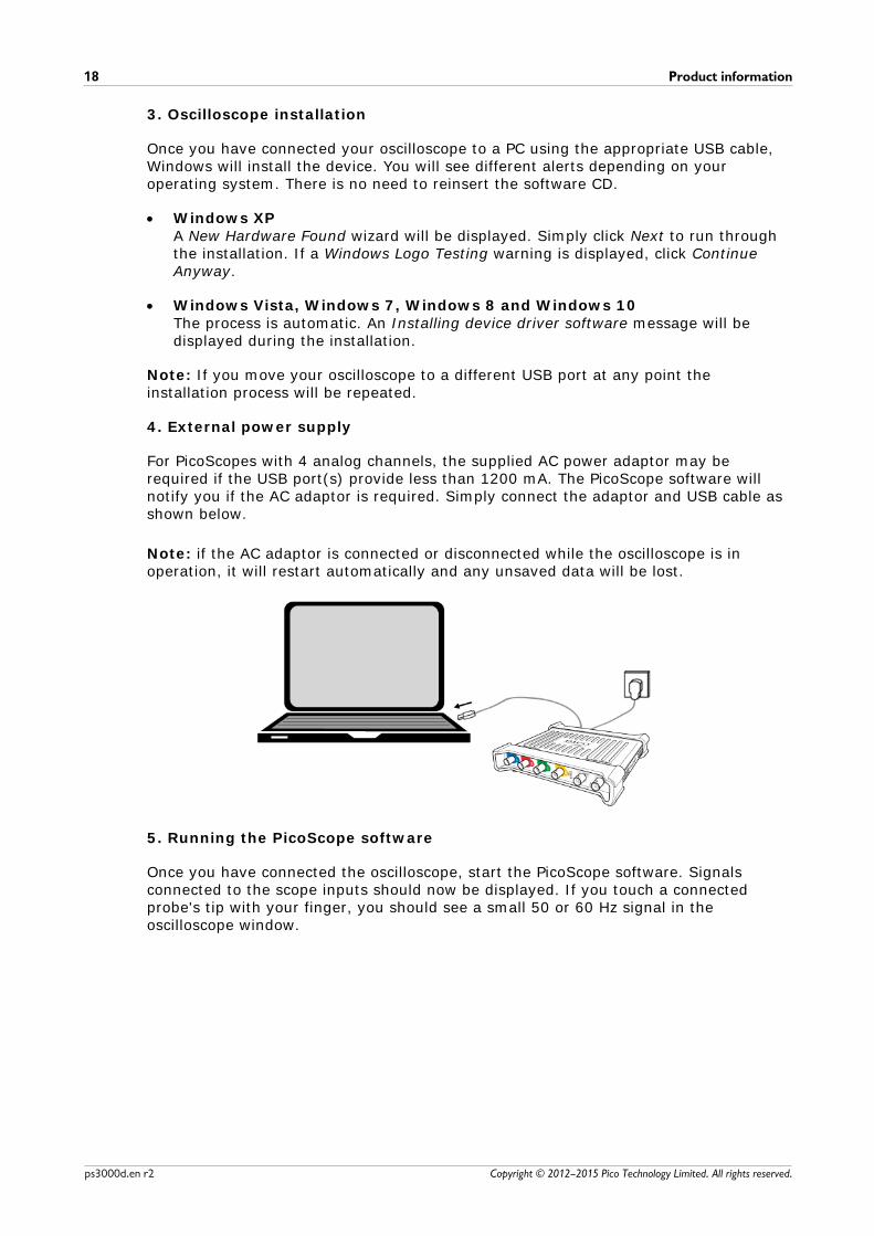
4. External power supply
For PicoScopes with 4 analog channels, the supplied AC power adaptor may berequired if the USB port(s) provide less than 1200 mA. The PicoScope software willnotify you if the AC adaptor is required. Simply connect the adaptor and USB cable asshown below.
Note: if the AC adaptor is connected or disconnected while the oscilloscope is inoperation, it will restart automatically and any unsaved data will be lost.
5. Running the PicoScope software
Once you have connected the oscilloscope, start the PicoScope software. Signalsconnected to the scope inputs should now be displayed. If you touch a connectedprobe's tip with your finger, you should see a small 50 or 60 Hz signal in theoscilloscope window.
PicoScope 3000D Series Oscilloscope & MSO User's Guide 19
Copyright © 2012–2015 Pico Technology Limited. All rights reserved. ps3000d.en r2
2.3 Minimum system requirementsTo ensure that your PicoScope 3000 Series oscilloscope operates correctly, you musthave a computer with the system requirements and one of the operating systemsshown in the table below. The performance of the oscilloscope will be better with amore powerful PC, and will greatly benefit from a multi-core processor.
Item Specification
Operating system
Windows 7, Windows 8 (not Windows RT), Windows 10*.
32 bit and 64 bit versions.
Beta software is also available for Linux and OS X operating
systems.
Processor
As required by the operating system Memory
Free disk space
PortsUSB 3.0 or USB 2.0 port(s)**
* PicoScope version 6.11 and SDKs are compatible with Windows XP SP3 andVista SP2 in addition to the Windows versions listed above. For bestperformance we recommend Windows 7 or later.
** See Connectivity, power and installation for more information.
Product information20
Copyright © 2012–2015 Pico Technology Limited. All rights reserved.ps3000d.en r2
2.4 Pack contentsAll PicoScope 3000 Series oscilloscope kits contain:
· PicoScope 3000 Series oscilloscope· Quick Start Guide· Software and reference CD· USB 3.0 cable*
Each model is also supplied with probes and additional items as shown below.
Probes (x1/x10, 1.2 m)
Digital cable Test clipsAC poweradaptor
3203D60 MHz (x2)
- -
-
3203D MSO 3204D
150 MHz (x2)- -
3204D MSO 3205D
150 MHz (x2)- -
3205D MSO 3206D
250 MHz (x2)- -
3206D MSO 3403D
60 MHz (x4)- -
3403D MSO 3404D
150 MHz (x4)- -
3404D MSO 3405D
150 MHz (x4)- -
3405D MSO 3406D
250 MHz (x4)- -
3406D MSO
* For more information on USB cables, see Connectivity, power and installation.
Each PicoScope 3000 Series oscilloscope is supplied with two or four probes that havebeen selected for use with that model. For optimal performance, always use the probesprovided. Although other oscilloscope probes can be used, the specified performancecannot be guaranteed. Replacement probes can be ordered at www.picotech.com.
PicoScope 3000D Series Oscilloscope & MSO User's Guide 21
Copyright © 2012–2015 Pico Technology Limited. All rights reserved. ps3000d.en r2
2.5 Compensating probesWe recommend that you compensate each oscilloscope probe before using it with yourPicoScope, and repeat the procedure before using the probes for any precisemeasurement applications.
Specific compensation instructions and all required compensation accessories aresupplied with each probe kit.
Connecting a probe for compensation
1. Plug the probe's BNC connector into an input channel on the oscilloscope.
2. Fit the spring hook on to the probe tip.
3. Attach the spring hook to the probe compensation pin on the front panel of theoscilloscope.
4. Attach the ground lead to the probe.
5. Connect the crocodile clip to the ground shell of another input channel.
6. Run the PicoScope software.
7. Follow these steps using the PicoScope software:
a. Set the input coupling to DC.
b. Set the scope trigger to the channel you are compensating.
c. Click Auto Setup.
8. Follow the compensation instructions supplied with the probe kit.
Glossary22
Copyright © 2012–2015 Pico Technology Limited. All rights reserved.ps3000d.en r2
3 GlossaryAPI. Application Programming Interface. A set of function calls that give programmersaccess to the PicoScope 3000 Series (A API) driver.
AWG. Arbitrary waveform generator. A signal generator that can play back awaveform of any shape defined by the user.
Bandwidth. The range of input frequencies over which the measured signal amplitudeis no more than 3 decibels below its true value.
Buffer size. The size of the oscilloscope buffer memory, measured in samples. Inblock mode, the buffer memory is used by the oscilloscope to store temporary data.This allows the oscilloscope to sample data independently of the speed at which it cantransfer data to the computer.
Driver. A program that controls a piece of hardware. The driver for the PicoScope3000 Series (A API) oscilloscopes is supplied in the form of a 32-bit or 64-bit WindowsDLL, ps3000a.dll. This is used by the PicoScope software, and by user-designedapplications, to control the oscilloscopes.
External trigger. The BNC connector marked EXT on the oscilloscope. It can be usedas a trigger source but not as a waveform input.
GS/s. Gigasamples (billions of samples) per second. Used to quantify thesampling rate of an oscilloscope.
Maximum sampling rate. A figure indicating the maximum number of samples theoscilloscope can acquire per second. Maximum sampling rates are usually given inMS/s (megasamples per second) or GS/s (gigasamples per second.) The higher thesampling rate of the oscilloscope, the more accurate the representation of the high-frequency details in a fast signal.
MS/s. Megasamples (millions of samples) per second. Used to quantify thesampling rate of an oscilloscope.
MSO. Mixed-signal oscilloscope. An oscilloscope that has both analog and digitalinputs.
PC oscilloscope. A virtual instrument formed by connecting a PicoScope oscilloscopeto a computer running the PicoScope software.
PicoScope software. The software product that accompanies all Pico Technologyoscilloscopes. It enables your PC to be an oscilloscope, spectrum analyzer, and meterdisplay.
Signal generator. A built-in circuit that generates signals suitable for driving anexternal device under test. Its output is the BNC connector marked GEN or AWG onthe oscilloscope. Connect a BNC cable between this output and one of the channelinputs to send a signal into the channel.
Timebase. A timer that controls the speed at which the scope captures data. At slowtimebases this process is visible as PicoScope draws the trace across the scope viewfrom left to right. At fast timebases PicoScope draws the whole trace in a singleoperation. The timebase is measured in units of time (such as seconds) per division.There are ten divisions across the scope view, so the total time across the width of theview is ten times the "per division" setting.
PicoScope 3000D Series Oscilloscope & MSO User's Guide 23
Copyright © 2012–2015 Pico Technology Limited. All rights reserved. ps3000d.en r2
USB. Universal serial bus. A standard port that enables you to connect externaldevices to a computer.
USB 1.1. An early version of the USB standard, found on some older PCs. PicoScopeswill operate slowly using a USB 1.1 port; performance will be greatly improved byusing the recommended USB 2.0 or 3.0 port.
USB 2.0. A USB 2.0 port uses signaling speeds of up to 480 megabits per second andis backwards-compatible with USB 1.1.
USB 3.0. A USB 3.0 port uses signaling speeds of up to 5 gigabits per second and isbackwards-compatible with USB 2.0 and USB 1.1.
Vertical resolution. A value, in bits, indicating the precision with which theoscilloscope converts input voltages to digital values. The resolution enhancementfunction can enhance the effective vertical resolution.
Voltage range. The range of input voltages that the oscilloscope can measure. Forexample, a voltage range of ±20 V means that the oscilloscope can measure voltagesbetween -20 V and +20 V. Input voltages outside of this range will not be measuredcorrectly. However they will not damage the instrument as long as they remain withinthe overvoltage protection range stated in the specifications.

PicoScope 3000D Series Oscilloscope & MSO User's Guide 25
Copyright © 2012–2015 Pico Technology Limited. All rights reserved. ps3000d.en r2
Index
AArbitrary waveform generator (Gen) 12, 13, 14,15
CCE notice 8
Cleaning 7
DDC power 13, 15
Digital inputs 14, 15, 16
EEarth terminal 12, 13, 14, 15
EXT connector 12, 13
External trigger 12, 13
FFCC notice 8
GGen output 12, 13, 14, 15
Grounding 6
HHumidity 7
IInput channels 12, 13, 14, 15
Input ranges 5
Installation guide 20
LLED 12, 13, 14, 15
License conditions 9
MMixed-signal oscilloscope (MSO) 14, 15, 16
PPicoScope software 18, 19
Power adaptor 6, 20
Probe compensation pin 13, 14, 15
Probes 20
compensating 21
RRepair 7
SSafety symbols 4
Servicing 7
Software and reference CD 20
System requirements 19
TTemperature 7
Trademarks 9
UUSB cable 20
USB port 12, 13, 14, 15, 17, 19
USB power 17
WWarranty 10

United Kingdom headquarters
Pico TechnologyJames HouseColmworth Business ParkSt. NeotsCambridgeshirePE19 8YPUnited Kingdom
Tel: +44 (0) 1480 396 395Fax: +44 (0) 1480 396 296
[email protected]@picotech.com
www.picotech.com
Copyright © 2012–2015 Pico Technology Limited. All rights reserved.
ps3000d.en r2 2015-12-04
United States headquarters
Pico Technology320 N Glenwood BlvdTylerTexas 75702United States
Tel: +1 800 591 2796Fax: +1 620 272 0981


![MSO/DS2000A Series Digital Oscilloscope · MSO/DS2202A/2202A-S: 1.8 ns MSO/DS2102A/2102A-S: 3.5 ns MSO/DS2072A/2072A-S: 5 ns DC Gain Accuracy[3] ±2% full scale DC Offset Accuracy](https://img.pdfslide.us/doc/110x75/6000e6c7dde05f20c43f2bd6/msods2000a-series-digital-oscilloscope-msods2202a2202a-s-18-ns-msods2102a2102a-s.jpg)