Embed Size (px)
Citation preview

Computers & Graphics 36 (2012) 548–554
Contents lists available at SciVerse ScienceDirect
Computers & Graphics
0097-84
http://d
$If a
online
008.n Corr
E-m
journal homepage: www.elsevier.com/locate/cag
SMI 2012: Short Paper
Mixed-element volume completion from NURBS surfaces$
Tobias Martin a,c,n, Elaine Cohen a, Robert M. Kirby b
a School of Computing, University of Utah, United Statesb Scientific Computing and Imaging Institute, University of Utah, United Statesc ETH Zurich, Switzerland
a r t i c l e i n f o
Article history:
Received 3 December 2011
Received in revised form
15 March 2012
Accepted 17 March 2012Available online 28 March 2012
Keywords:
Model completion
Volumetric parameterization
Meshing
Physically-based animation and simulation
93/$ - see front matter & 2012 Elsevier Ltd. A
x.doi.org/10.1016/j.cag.2012.03.008
pplicable, supplementary material from the
after the conference. Please see http://dx.d
esponding author.
ail address: [email protected] (T. Martin).
a b s t r a c t
In this paper we present a methodology to create a volumetric representation from a 2-manifold
without boundaries represented with untrimmed NURBS surfaces. A trivariate NURBS representation is
difficult to construct from such a representation, especially when the input surface patches were
created with only a boundary representation as the goal. These kinds of inputs arise in numerous
existing geometric modeling scenarios such as models from CAD systems, subdivision surfaces,
quadrilateral meshing and data-fitting. Our approach, nearly automatic and only requiring minimal
user input, creates a hybrid representation using trivariate NURBS elements at the boundary and
unstructured tetrahedral elements in the interior of the object. The original boundary representation of
the input model is maintained in the final representation, allowing the volumetric representation to be
used in both computer graphics simulations and isogeometric analysis applications. We demonstrate
that the hybrid representation yields convergence under model refinement, and that it can be used
efficiently in elastic body simulation.
& 2012 Elsevier Ltd. All rights reserved.
1. Introduction
Objects represented with NURBS surfaces are widely used incomputer graphics and engineering applications. A subdivisionsurface is frequently converted into a set of NURBS surfacesfor rendering purposes, and mechanical parts are modeled orreverse-engineered using NURBS patches of higher-order poly-nomial degrees. In the isogeometric analysis paradigm [1],smooth basis functions used to model the smooth geometry arealso used as basis for the simulation. The analysis result is storedas an attribute of the model representation. This avoids both theneed to generate a finite element mesh and the need to reverse-engineer a CAD model from the finite element mesh. However, avolumetric representation must be generated if a simulationmethodology is to be applied to the volume of the input.
If the input consists of NURBS surface patches and if itsparameterization must be maintained in the resulting volumetricrepresentation, it is a difficult problem to complete its volumewith trivariate NURBS elements, and has not been solved forarbitrary shapes models. In practice, a volumetric representationis constructed that either consists of (1) classic finite elements(e.g., [2,3]) or (2) larger smooth trivariate B-spline patches.Methods in category (1) are mostly automatic. Methods in
ll rights reserved.
author(s) will be available
oi.org/10.1016/j.cag.2012.03.
category (2) (e.g., [4–10]) are generally based on a volumetricparameterization established on the volume from which thevolumetric representation is constructed and may require userinteraction. While in both categories, a full volumetric hexahedralrepresentation is created, the original higher-order representationis not part of the simulation representation. Therefore, theisogeometric analysis paradigm is not fully implemented.
This paper makes three contributions: (1) Presentation of a newmixed volumetric representation that keeps the original NURBSsurface representation and parameterization. (2) Creation of asemi-structured NURBS volume with arbitrary thickness as a userparameter (with a few restrictions), where the remaining interiorvolume is completed with unstructured tetrahedra (Fig. 1). (3) Acollocation approach which unifies the different element typesand verification of the representation in a simulation setting.
The proposed approach, based on harmonic functions [11] anda sampled midstructure, allows offsetting the input model into itsinterior without creating degenerate elements to produce a volu-metric semi-structured NURBS volumetric mesh offset inwardfrom the boundary of the object. It significantly reduces the timeneeded to create a volumetric model and avoids the correspon-dence problem by matching the interior boundary NURBS ele-ments with linear tetrahedra.
NURBS elements require more computational effort duringsimulation, e.g., numerical integration and evaluation of simula-tion quantities due to higher-order polynomial degree. Thesequantities can be efficiently evaluated on linear tetrahedra dueto its lower degree. However, simulation applied to structuredNURBS elements can produce simulation results of higher quality

T. Martin et al. / Computers & Graphics 36 (2012) 548–554 549
because of smoothness across elements [1]. Fig. 2 illustrates thatthe proposed representation can be useful in applications such asanimating elasticity, where high quality NURBS elements on thedomain’s boundary prevent element degeneracies. Linear ele-ments, prone to flipping in non-linear simulation scenarios, areplaced away from the critical regions, and the overall impressionof the animation visually appears smoother as well.
Related work is discussed in Section 2, the hybrid representa-tion is introduced in Section 3. Section 4 verifies convergence ofthe hybrid representation under refinement. The paper discussesresults in Section 5 and concludes in Section 6.
2. Related work
Hybrid meshing or mixed element methods, where prisms orhexahedra are combined with tetrahedra, have been used invarious engineering scenarios, e.g., aerospace applications [12],geophysics applications and computation fluid dynamics applica-tions [13]. If the input surface is a quadrilateral mesh, pyramidsare used to transition from boundary hexahedra to tetrahedra.H-morph [14], based on an advancing front scheme, iterativelyconverts an input tetrahedral mesh into a hexahedral mesh.Tetrahedral elements that cannot be converted into hexahedralelements are connected to their adjacent hexahedral elementsusing pyramids.
In these cases, C0 continuity between two element types ismaintained. Our approach does not enforce such continuity and inthat respect is similar to, and motivated by approaches discussedin the introduction of Section 3.4, where the nodes defining thelinear tetrahedra are linked to these higher-order elements. Weshow that the resulting representation yields convergence under
Fig. 1. Hybrid representation: tri-cubic NURBS elements (red) at the boundary.
Linear tetrahedra (gray) in the interior of the object. The surface patches are
constructed using Catmull–Clark subdivision. (For interpretation of the references
to color in this figure legend, the reader is referred to the web version of this
article.)
Ground Plane
Initial Location
No Boundary LayerGravity 1 Boundary La
Fig. 2. Effect of C2 elements at domain boundary: the configuration of this 2D elasticity
on the left. The top row shows the state of maximal impact, i.e., the state where the ela
The bottom row shows the final state of the object. By increasing the number of bound
elements. Note, due to the gravitational force the final shape is not circular.
mesh refinement. It will also be shown that our hybrid approachhas a similar convergence rate to a representation which usesonly tetrahedral elements, but has the added benefit that it canavoid some of the stability problems of tetrahedra only meshes.
In a similar vein to our work is the method in [15] generating ahybrid mesh consisting of prisms and tetrahedra. The hybridrepresentation is constructed from a triangulated surface repre-senting the domain of interest. This triangulated surface isoffset along a marching direction. A marching vector of a nodeis determined through local geometric constraints and a marchingstep size is chosen to reduce curvature from that of the previousmarching surface. Similarly, [16] uses solutions to the Eikonalequation. Finally, tetrahedra are used to fill up the rest of theobject. More recently, [17] first computes a distance field from aninput triangle mesh. Based on a user specified thickness para-meter, an isosurface of the distance field is extracted and ahexahedral shell mesh based on a polycube domain [18] andharmonic functions is constructed, i.e., the remaining volume inthe object is void. Peng et al. [19] proposes a method to addvolume textures to an input surface. The method offsets the inputsurface based on an ODE. The ODE is designed such that the limitoffset surface is the medial axis of the input surface. Note, whenthe input surface contains sharp edges the medial axis touchesthe input surface, and the outer layer is very thin at thesharp edges.
In our approach, harmonic functions are used in combinationwith a midstructure representation to define the offset functionfor the exterior surface. The flexibility of harmonic functionsallow the user to specify any appropriate midstructure, e.g., apoint-sampled simplified medial axis or a 1D curve skeletonof the object or an isosurface as used in [17]. Also, marchingdirections and step sizes are implicitly determined and guaranteenot to introduce degenerate elements because of the maximumprinciple of harmonic functions. Furthermore, compared to nor-mal offsetting, harmonic functions allow offsetting the inputsurface deeper into the interior of the object. The remainingvolume is completed with tetrahedra.
3. Volumetric representation
This section describes our proposed modeling pipeline. Let thedomain of interest be the input S, a 2-manifold without bound-aries. S consists of a collection of coefficients clAR3 and asso-ciated weights hlAR and a set of parametric patches sk, defined as
skðu,vÞ :¼
Ppi ¼ 0
Pqj ¼ 1 hi,jci,jBi,p,tu
ðuÞBj,q,tvðvÞ
Ppi ¼ 0
Pqj ¼ 1 hi,jBi,p,tu
ðuÞBj,q,tvðvÞ
, ð1Þ
State of Max. Impact
Final State
2 Boundary Layers 3 Boundary Layersyer
example, based on a Hookean material using Chauchy–Green strain, is illustrated
stic potential energy reaches its maximum, when the shape hits the ground plane.
ary layers and its thicknesses, the corresponding final states do no exhibit flipped

Input: NURBS surface& midstructure
Intermediatetetrahedral mesh
Trivariate NURBSelements
Output: Hybridvolumetric representation
Solve Laplace’sEquation
OffsetNURBS surfaces
Fill interior
Fig. 3. The input are NURBS surface patches, in these cases generated from a Catmull–Clark subdivision model. A sampled midstructure such as a simplified medial axis is
used to generate trivariate NURBS patches at the boundary of the volumetric representation. The remaining interior is filled up with unstructured tetrahedral elements.
(Elements in (b)–(d) are culled to visualize the interior.)
T. Martin et al. / Computers & Graphics 36 (2012) 548–554550
where Bi,p,tuðuÞ and Bj,q,tv
ðvÞ are B-spline basis functions as definedin [20], p and q the degrees and tu and tv the local knot vectors ofpatch skðu,vÞ. The coefficients ci,j with corresponding scalarweights hi,j define a control mesh of dimension ðpþ1Þ � ðqþ1Þ.Note that the indices ði,jÞ in Eq. (1) are local to the patch skðu,vÞ,i.e., there exists a mapping to a global index l.S and an associated sampled midstructure (generated by using
one of several methods, e.g., [21]) are used to construct avolumetric representation in four steps, as shown in Fig. 3.
Step 1.
Triangulate control mesh and create unstructured tetra-hedral mesh containing the point-sampled midstructure,Section 3.1Step 2.
Construct a harmonic function on the tetrahedral mesh(Fig. 3b), Section 3.1Step 3.
Offset the input surface using the harmonic function,allowing the user to specify the thickness of the resultingsemi-structured volumetric NURBS representation(Fig. 3c), Section 3.2Step 4.
Triangulate the limit surface (green surface in Fig. 3c)which has the same mesh layout as the input, and fill itsinterior with unstructured tetrahedral elements (Fig. 3d),Section 3.4The general definition of S and its patches skðu,vÞ allow a widerange of input representations. For instance, if the input is anunstructured quadrilateral mesh, then skðu,vÞ defines a bi-linearpatch with p¼ q¼ 1 and tu ¼ tv ¼ f0;0,1;1g and hl¼1. A moregeneral input may use different weights and a mix of floating andopen knot vectors (see [20]), allowing higher continuity amongadjacent patches and the representation of rational geometries.
3.1. Harmonic mapping
The first step in our framework consists of triangulating the set ofcoefficients cl, by triangulating the regular local control mesh ci,j foreach patch skðu,vÞ as defined in Eq. (1). From this triangle mesh and asampled midstructure of S, an unstructured tetrahedral mesh H isconstructed (e.g., by using [3]). Let V be the set of vertices inH. Let VE
be the set of vertices on the boundary of H and VI be the set of
vertices defining the midstructure of S lying in the interior ofH. Note,VE and VI are subsets of V and also that VE may contain vertices inaddition to the coefficients cl, depending on the tetrahedralization.
Given H, VE and VI , a scalar function w on H is computed suchthat it satisfies Laplace’s equation,
r2w¼ 0: ð2Þ
w is harmonic and satisfies the maximum principle, and thereforehas been used in the domain of meshing and volumetric para-meterization (e.g., [7,17]).
The finite element method [22] is used to discretize Eq. (2).Vertices in VE are set to 0, vertices in VI are set to 1 (Dirichlet BC).With this setup wðx,y,zÞ evaluates to 0 at the boundary ofH and to1 at vertices defining the midstructure (see Fig. 3b). A solution hasthe form wðx,y,zÞ ¼
Pvk AVwkfkðx,y,zÞ, where fkðx,y,zÞ are linear
hat functions [22] associated with the respective vertices in H.Galerkin’s formulation [22] is used to set up a linear system whichis solved to assign a harmonic value with every vertex in V. Thegradient field rw over H is piece-wise constant, flowing towardsthe sampled midstructure.
3.2. Offset input surface
The harmonic function wðx,y,zÞ is used to offset the vertices cl
defining S into the interior of S. In a first step, the user is giventhe ability to choose a parameter value w0A ½0;1�, allowing theuser to control the volume enclosed by S and the isosurfacewðx,y,zÞ ¼w0 (see Fig. 3c). Once this choice has been made, theremaining pipeline stages proceed automatically. Note that sincethe midstructure representation is sampled, the isosurface at w0
could be of higher genus than the input S, especially when w0 isclose to 1. The proposed method requires that the isosurface at w0
and the input has the same genus, i.e., the user must choose a w0
that satisfies this condition.For every cl defining the input surface S a path glðoÞ,
gl : R-R3, is constructed emanating from cl by following rw
and terminating at point cl, where wðclÞ ¼w0, i.e., glð0Þ ¼ cl andglðw0Þ ¼ cl. Note that glðoÞ is parameterized through wðx,y,zÞ. LetS be the surface defined with the coefficients cl (see green surfacein Fig. 3c), with corresponding surface patches skðu,vÞ.
T. Martin et al. / Computers & Graphics 36 (2012) 548–554 551
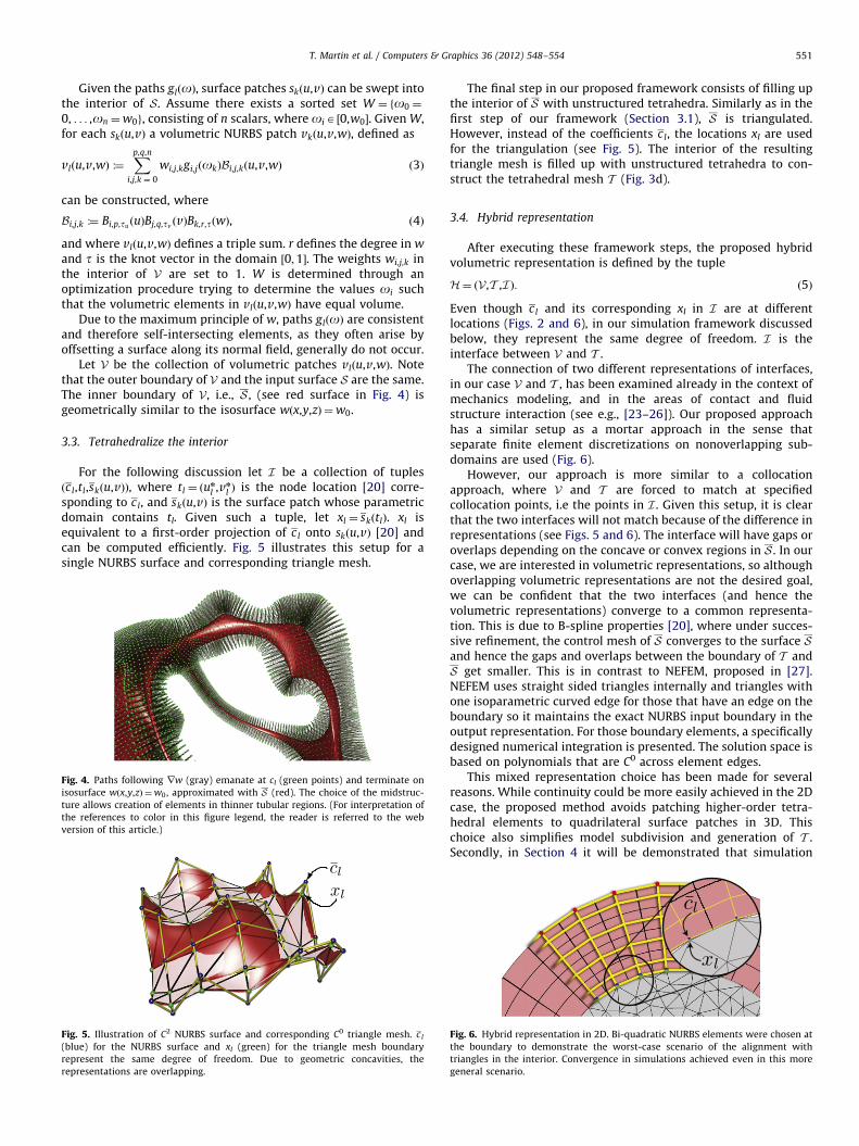
Given the paths glðoÞ, surface patches skðu,vÞ can be swept intothe interior of S. Assume there exists a sorted set W ¼ fo0 ¼
0, . . . ,on ¼w0g, consisting of n scalars, where oiA ½0,w0�. Given W,for each skðu,vÞ a volumetric NURBS patch vkðu,v,wÞ, defined as
vlðu,v,wÞ :¼Xp,q,n
i,j,k ¼ 0
wi,j,kgi,jðokÞBi,j,kðu,v,wÞ ð3Þ
can be constructed, where
Bi,j,k :¼ Bi,p,tuðuÞBj,q,tv
ðvÞBk,r,tðwÞ, ð4Þ
and where vlðu,v,wÞ defines a triple sum. r defines the degree in w
and t is the knot vector in the domain ½0;1�. The weights wi,j,k inthe interior of V are set to 1. W is determined through anoptimization procedure trying to determine the values oi suchthat the volumetric elements in vlðu,v,wÞ have equal volume.
Due to the maximum principle of w, paths glðoÞ are consistentand therefore self-intersecting elements, as they often arise byoffsetting a surface along its normal field, generally do not occur.
Let V be the collection of volumetric patches vlðu,v,wÞ. Notethat the outer boundary of V and the input surface S are the same.The inner boundary of V, i.e., S , (see red surface in Fig. 4) isgeometrically similar to the isosurface wðx,y,zÞ ¼w0.
3.3. Tetrahedralize the interior
For the following discussion let I be a collection of tuplesðcl,tl,skðu,vÞÞ, where tl ¼ ðu
n
l ,vn
l Þ is the node location [20] corre-sponding to cl, and skðu,vÞ is the surface patch whose parametricdomain contains tl. Given such a tuple, let xl ¼ skðtlÞ. xl isequivalent to a first-order projection of cl onto skðu,vÞ [20] andcan be computed efficiently. Fig. 5 illustrates this setup for asingle NURBS surface and corresponding triangle mesh.
Fig. 4. Paths following rw (gray) emanate at cl (green points) and terminate on
isosurface wðx,y,zÞ ¼w0, approximated with S (red). The choice of the midstruc-
ture allows creation of elements in thinner tubular regions. (For interpretation of
the references to color in this figure legend, the reader is referred to the web
version of this article.)
Fig. 5. Illustration of C2 NURBS surface and corresponding C0 triangle mesh. cl
(blue) for the NURBS surface and xl (green) for the triangle mesh boundary
represent the same degree of freedom. Due to geometric concavities, the
representations are overlapping.
The final step in our proposed framework consists of filling upthe interior of S with unstructured tetrahedra. Similarly as in thefirst step of our framework (Section 3.1), S is triangulated.However, instead of the coefficients cl, the locations xl are usedfor the triangulation (see Fig. 5). The interior of the resultingtriangle mesh is filled up with unstructured tetrahedra to con-struct the tetrahedral mesh T (Fig. 3d).
3.4. Hybrid representation
After executing these framework steps, the proposed hybridvolumetric representation is defined by the tuple
H¼ ðV,T ,I Þ: ð5Þ
Even though cl and its corresponding xl in I are at differentlocations (Figs. 2 and 6), in our simulation framework discussedbelow, they represent the same degree of freedom. I is theinterface between V and T .
The connection of two different representations of interfaces,in our case V and T , has been examined already in the context ofmechanics modeling, and in the areas of contact and fluidstructure interaction (see e.g., [23–26]). Our proposed approachhas a similar setup as a mortar approach in the sense thatseparate finite element discretizations on nonoverlapping sub-domains are used (Fig. 6).
However, our approach is more similar to a collocationapproach, where V and T are forced to match at specifiedcollocation points, i.e the points in I . Given this setup, it is clearthat the two interfaces will not match because of the difference inrepresentations (see Figs. 5 and 6). The interface will have gaps oroverlaps depending on the concave or convex regions in S . In ourcase, we are interested in volumetric representations, so althoughoverlapping volumetric representations are not the desired goal,we can be confident that the two interfaces (and hence thevolumetric representations) converge to a common representa-tion. This is due to B-spline properties [20], where under succes-sive refinement, the control mesh of S converges to the surface Sand hence the gaps and overlaps between the boundary of T andS get smaller. This is in contrast to NEFEM, proposed in [27].NEFEM uses straight sided triangles internally and triangles withone isoparametric curved edge for those that have an edge on theboundary so it maintains the exact NURBS input boundary in theoutput representation. For those boundary elements, a specificallydesigned numerical integration is presented. The solution space isbased on polynomials that are C0 across element edges.
This mixed representation choice has been made for severalreasons. While continuity could be more easily achieved in the 2Dcase, the proposed method avoids patching higher-order tetra-hedral elements to quadrilateral surface patches in 3D. Thischoice also simplifies model subdivision and generation of T .Secondly, in Section 4 it will be demonstrated that simulation
Fig. 6. Hybrid representation in 2D. Bi-quadratic NURBS elements were chosen at
the boundary to demonstrate the worst-case scenario of the alignment with
triangles in the interior. Convergence in simulations achieved even in this more
general scenario.

T. Martin et al. / Computers & Graphics 36 (2012) 548–554552
convergence on a 2D problem is achieved. Furthermore, theaccompanied video shows that dynamic physically-based anima-tion is efficiently applied to the 3D case.
Given a static or dynamic problem, discretized using the finiteelement method [22], in the general case, there exists a solutionfunction a : O-Rd. For instance in linear elasticity d¼3 where adescribes a displacement field defined over O, or in heat conduc-tion where a represents a temperature scalar field defined over O,i.e., d¼1. In our framework O is represented with H.
Given a tuple ðcl,tl,skðu,vÞÞAI . Let al be the coefficient corre-sponding to the vertex xl of a tetrahedron in T . Note that aevaluates to al at this tetrahedron at xl, i.e., al :¼ aðxlÞ. Let as be theevaluation of a at skðtlÞ, i.e., as :¼ aðskðtlÞÞ. Given the discontinuousnature of H, at aas even though xl ¼ skðtlÞ. Therefore, beforesimulation proceeds, as is assigned to the coefficient al. Thisenforces that aðskðtlÞÞ and aðxlÞ match. In Section 4 we demon-strate that convergence can be achieved with the proposedcollocation-based approximation.
3.5. Robustness and practical considerations
S tends to have self-intersections if the input surface containshighly stretched elements, e.g., see Fig. 1. Therefore, before thehybrid representation generation framework is executed, the inputsurface is appropriately refined, such that elements have similarsize and shape. While the element count of the input surface isincreased, the resulting triangle mesh corresponding to S has abetter quality and is more suitable to generate a tetrahedral mesh.Furthermore, while paths computed from a harmonic field areguaranteed to be free of intersections, paths traced on a discretizedfield can overlap. The resulting higher-order elements comprisingthe thick shell can therefore have self-intersections which should beavoided. Similarly to the method in [7], paths are traced simulta-neously in small steps, where in each step the front defined by thepath endpoints are smoothed using a Laplacian smoothing schemesuch that endpoints remain on the corresponding isosurface.
4. Convergence study in 2D
Here, we examine a study in 2D to show that our proposedhybrid representation as discussed in Section 3.4 produces com-parable simulation results with respect to convergence ratesunder h-refinement [22] as the equivalent representation whichuses only triangles.
We are given the smooth function g : O-R
gðx,yÞ :¼ Jð4,J0ð4;2Þrðx,yÞÞsinð4yðx,yÞÞ, ð6Þ
where rðx,yÞ :¼ffiffiffiffiffiffiffiffiffiffiffiffiffiffiffix2þy2
p, and yðx,yÞ defines the angle between
vector ðx,yÞ and the Cartesian coordinate axes, i.e., rðx,yÞ and yðx,yÞ
1000 50002000 30001500
1.00
0.50
0.30
0.70
Err
or
n
Hybrid
Triangles
y
x
Fig. 7. Left: convergence plot comparing the hybrid representation with the represent
between the approximated and true solution. n is the degree of freedoms for the refine
only representation (right), during a h-refinement step.
convert ðx,yÞ into polar coordinates. O in this study represents adisk centered at the origin with a radius of 1 with boundary @O.Furthermore, Jðn,zÞ is the nth Bessel function of the first kind atzAR, and J0ðn,mÞ is the mth zero of the nth Bessel function of thefirst kind. Since gðx,yÞ ¼ 0 at @O, the Dirichlet boundary conditionat @O is set to zero. In the following experiment, let f ðx,yÞ :¼ r2g.
In this study we investigate Poisson’s equation �r2 ~g ¼ f , solvedusing Galerkin’s method on two disk representations: (1) the disk isrepresented with NURBS elements at the boundary and triangles inthe interior using the hybrid framework as discussed in Section 3.4;(2) the disk is represented with triangles only. Both representationsare refined three times where the error 9gðx,yÞ� ~g ðx,yÞ92 is computedfor each refinement step. The corresponding log–log diagram isshown in Fig. 7. The figure also shows the disk representations at anintermediate refinement step and the corresponding solution alongthe z-axis of the respective disk.
The convergence of a triangle representation to the truesolution is hpþ1, where p is the order on element and h its radius.For instance, quadratic NURBS elements therefore have a cubicconvergence rate [28], while linear tetrahedral elements convergequadratically. However, as the experiment in this section shows,under h-refinement, the slope for both representations is approxi-mately �2 indicating quadratic convergence even in the presenceof higher-order NURBS elements. Our hybrid representation hastwo inherent approximation errors: (1) geometric approximationerror of the interior representation and (2) approximation error ofthe field. Since both geometric subdivision and linear triangleelements have a quadratic convergence rate, the overall conver-gence rate is quadratic as well. We did not study the effects fromvarying depths of the NURBS representation and how conver-gence is affected. This is subject to future research.
5. Results
We applied the proposed approach to the following closed inputobjects, represented with the bi-cubic patches: B-spline surfacescomputed from Catmull–Clark subdivision surfaces shown inFigs. 1 and 3; Bezier surfaces with G1 continuity computed fromquadrilateral meshes computed using the approach by [29] shownin Fig. 8(a) and (b); NURBS surfaces approximating a mechanicalpart with C2 continuity in the interior and C0 at adjacent surfacepatches (Fig. 8(c)). In all cases, a cubic knot vector is used for the w-direction. In the current framework, the midstructure has beencomputed using the tight co-cone approach [21], where for somemodels, the resulting medial axis has been manually simplified. Forinstance, for the fandisk model (Fig. 8(c)), sheets corresponding tosharp features were manually removed. Although manual medialaxis simplification is a time-consuming procedure, our approachonly requires a sampling of a midstructure and does not require
x
y
ation which only uses triangles. For the error computation, we chose the l2 norm
ment steps. Solutions along z-axis on hybrid representation (middle) and triangle

Fig. 8. Methodology applied to three objects. Object boundaries are shown in red, interior boundaries in green. The input for (a) and (b) are bi-cubic Bezier patches, and for
(c) bi-cubic NURBS surfaces. The wire-frame shows C0 continuities. (For interpretation of the references to color in this figure legend, the reader is referred to the web
version of this article.)
T. Martin et al. / Computers & Graphics 36 (2012) 548–554 553
proper topological connectivity, so the simplification was performedrapidly and did not exceed 10 min for each of the input models. Weapplied Laplacian smoothing and edge collapses to produce trianglesof similar size and area. The corresponding vertex set was used assampling for the intermediate tetrahedral mesh (Fig. 3(b)).
The only remaining user input to the subsequent pipelinestages was the choice of thickness of the outer B-spline volu-metric region as discussed in Section 3.1. The reason for this isthat a user might want to specify a different thickness dependingon the application. For instance, a thicker NURBS volume wouldresult in more high-order trivariate patches with wider basisfunction support, resulting in slightly slower simulation, buthigher simulation quality as illustrated in Fig. 2. However, forprototyping purposes, a user might choose thinner volumes tocompute simulation results more quickly.
The remaining computational step consisting of constructingLaplace’s matrix, tracing paths and creating volumetric elements,can be neglected as these operations can be parallelized andcomputed efficiently. Timings were less than 5 min for each of thetest models. As discussed in Section 3.2, after the user performedall required input, the sampling procedure in [7] is adapted forour context that resamples the paths to create roughly equalB-spline volumes by avoiding degenerate elements. Note that thisprocedure only re-samples the paths glðoÞ computed from theinput points and rw as discussed in Section 3.2 and does notrequire any other re-computation.
6. Conclusion
In this paper we proposed a framework to create a volumetricrepresentation from an input surface represented with untrimmedNURBS surfaces from various inputs, making the creation of avolumetric representation independent from creating the inputsurfaces. The approach is based on harmonic functions which areused to offset the input surface until a user-specified offsetdistance is reached. The remaining interior volume is filled withunstructured tetrahedra. A collocation approach is proposed toaddress the correspondence problem. The boundary surface of thevolumetric representation and the input surface are the same, i.e.,smoothness and geometry of the input surface is maintained inthe volumetric representation.
A limitation of the approach is the geometric discontinuitybetween the high-order boundary in the interior and the bound-ary of the interior tetrahedral mesh, where the convergence rateof the tetrahedral mesh is the limiting factor. We have demon-strated that the resulting hybrid volumetric representation is
stable, can be used in simulation scenarios, and is motivated bydiscontinuous hybrid simulation representations from otherareas. In future work, we plan to extend our framework so thatit can be applied to a wider range of element types, for instancehigher-order tetrahedral elements. Note that a fully continuousrepresentation is more difficult to achieve, mainly because of thesmooth input surface representations which can have an arbitrarychoice of continuity and smoothness properties.
In conclusion, we see our approach especially useful inapplications which require that the input surface parameteriza-tion must be maintained in the volumetric representation, suchas in isogeometric analysis. But the approach is also useful inapplications where the time to generate volumetric inputs islimited, requiring only little user input, which is generally desiredand even required in various computer graphics applications.
Acknowledgments
This publication is supported in part by NSF IIS-1117997 andARO W911NF-08-0517 (Program Manager Dr. Mike Coyle). Var-ious models in the paper are provided by the AIM@SHAPE ShapeRepository.
Appendix A. Supplementary material
Supplementary data associated with this article can be found inthe online version of http://dx.doi.org/10.1016/j.cag.2012.03.008.
References
[1] Hughes TJR, Cottrell JA, Bazilevs Y. Isogeometric analysis: Cad, finite ele-ments, nurbs, exact geometry, and mesh refinement. Comput Methods ApplMech Eng 2005;194:4135–95.
[2] Owen SJ. A survey of unstructured mesh generation technology. In: Interna-tional Meshing Roundtable; 1998. p. 239–67.
[3] Si H. Tetgen: a quality tetrahedral mesh generator and three-dimensionalDelaunay triangulator; 2005 /http://tetgen.berlios.deS.
[4] Wang H, Jin M, He Y, Gu X, Qin H. User-controllable polycube map formanifold spline construction. In: SPM ’08: proceedings of the 2008 ACMsymposium on solid and physical modeling. New York, NY, USA: ACM; 2008.p. 397–404.
[5] He Y, Wang H, Fu C-W, Qin H. Technical section: a divide-and-conquerapproach for automatic polycube map construction. Comput Graph2009;33(3):369–80.
[6] Li B, Li X, Wang K, Qin H. Generalized polycube trivariate splines. In: Shapemodeling international conference (SMI); 2010. p. 261–5. http://dx.doi.org/10.1109/SMI.2010.40.

T. Martin et al. / Computers & Graphics 36 (2012) 548–554554
[7] Martin T, Cohen E, Kirby RM. Volumetric parameterization and trivariateb-spline fitting using harmonic functions. Comput Aided Geom Des 2009;26:648–64.
[8] Martin T, Cohen E. Volumetric parameterization of complex objects byrespecting multiple materials. Comput Graph 2010;34(3):187–97.
[9] Nieser M, Reitebuch U, Polthier K. CUBECOVER—parameterization of 3dvolumes. Comput Graph Forum 2011;30(5):1397–406.
[10] Gregson J, Sheffer A, Zhang E. All-hex mesh generation via volumetricpolycube deformation. Comput Graph Forum 2011;30(5):1407–16.
[11] Ni X, Garland M, Hart JC. Fair morse functions for extracting the topologicalstructure of a surface mesh. In: Proceedings of the SIGGRAPH; 2004.
[12] Khawaja A, Kallinderi Y. Hybrid grid generation for turbomachinery andaerospace applications. Int J Numer Methods Eng 2000;49(1):145–66.
[13] Ito Y, Shih AM, Soni BK. Hybrid mesh generation with embedded surfacesusing a multiple marching direction approach. Int J Numer Methods Fluids2011;67(1):1–7. http://dx.doi.org/10.1002/fld.1962.
[14] Owen SJ, Saigal S. H-morph: an indirect approach to advancing front hexmeshing. Int J Numer Methods Eng 2000;49(1–2):289–312.
[15] Kallinderis Y, Khawaja A, Mcmorris H. Hybrid prismatic/tetrahedral gridgeneration for complex geometries. AIAA Paper 1996;34:93–0669.
[16] Wang Y, Murgie S. Hybrid mesh generation for viscous flow simulation. In:Pbay PP, editor. Proceedings of the 15th international mesh roundtable.Springer-Verlag; 2006. p. 109–26.
[17] Han S, Xia J, He Y. Hexahedral shell mesh construction via volumetricpolycube map. In: Proceedings of the 14th ACM symposium on solid andphysical modeling, SPM ’10. New York, NY, USA: ACM; 2010. p. 127–36.
[18] Tarini M, Hormann K, Cignoni P, Montani C. Polycube-maps. In: SIGGRAPH’04: ACM SIGGRAPH 2004 papers. New York, NY, USA: ACM; 2004. p. 853–60.
[19] Peng J, Kristjansson D, Zorin D. Interactive modeling of topologically complexgeometric detail. ACM Trans Graph 2004;23:635–43.
[20] Cohen E, Riesenfeld RF, Elber G. Geometric modeling with splines: an
introduction. Massachusetts, USA: A.K. Peters, Ltd.; 2001.[21] Dey TK, Goswami S. Tight cocone: a water-tight surface reconstructor. In: SM
’03: Proceedings of the eighth ACM symposium on solid modeling andapplications. New York, USA: ACM; 2003. p. 127–34.
[22] Hughes TJR. The finite element method: linear static and dynamic finiteelement analysis. Dover; 2000.
[23] Guillard H, Farhat C. On the significance of the geometric conservation lawfor flow computations on moving meshes. Comput Methods Appl Mech Eng2000;190(11–12):1467–82.
[24] Maday APY, Mavriplis C. Non-conforming mortar element methods: applica-tions to spectral discretizations. Domain Decomposition Methods, SIAM.
[25] Bernardi APC, Maday Y. A new nonconforming approach to domain decom-position: the mortar element method. In: Brezis H, Lions JL, editors. Non-
linear partial differential equations and their applications. Pitman/Wiley.[26] Kirby RM, Yosibash Z, Karniadakis GE. Towards stable coupling methods
for high-order discretization of fluid–structure interaction: algorithms andobservations. J Comput Phys 2007;223:489–518.
[27] Sevilla R, Fernandez-Mendez S, Huerta A. NURBS-enhanced finite elementmethod (NEFEM). Arch Comput Methods Eng 2011;18(4):441–84.
[28] Bazilevs L, Beirao da Veiga Y, Cottrell J, Hughes T, Sangalli G. Isogeometricanalysis: approximation, stability and error estimates for h-refined meshes.Math Methods Models Appl Sci 2006;16:1031–90.
[29] Ray N, Li WC, Levy B, Sheffer A, Alliez P. Periodic global parameterization.ACM Trans Graph 2006;25(4):1460–85.


![The weak substitution method – An application of the ...et... · NURBS [1,2,3], T-splines [4] and subdivision surfaces [5] are the most common ones. Akin to the prevalence of NURBS](https://img.pdfslide.us/doc/110x75/5f4f0cfff8fda559662ec56b/the-weak-substitution-method-a-an-application-of-the-et-nurbs-123.jpg)