Embed Size (px)
DESCRIPTION
MI Courseware MIT
Citation preview
Application of Newton’s Second Law Challenge Problem Solutions
Problem 1: Painter on a Platform
A painter of mass m1 stands on a platform of mass m2 and pulls himself up by two ropes that run over massless pulleys, as shown. He pulls on each rope with a force of magnitude F and accelerates upward with a uniform acceleration a . Find the acceleration a .
Problem 1 Solutions:
There are two separate and equally valid approaches to this question. The first is to draw two separate free body diagrams, one for the painter, and the other for the platform. Let a1 denote the magnitude of the acceleration of the painter. Let a2 denote the magnitude of the acceleration of the platform. The painter and the platform have the same acceleration upwards; these two magnitudes are equal, and we denote the common acceleration by the symbol a :
a1 = a2 ! a . (1.1)
Free Body Diagrams:
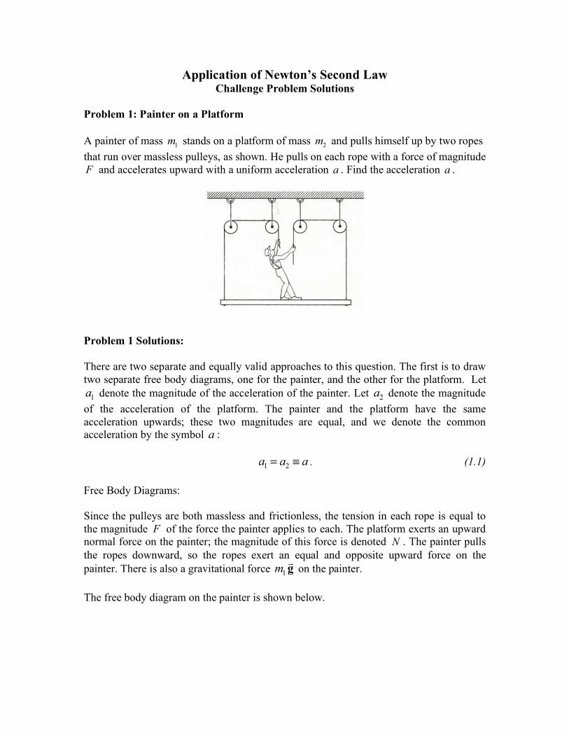
Since the pulleys are both massless and frictionless, the tension in each rope is equal to the magnitude F of the force the painter applies to each. The platform exerts an upward normal force on the painter; the magnitude of this force is denoted N . The painter pulls the ropes downward, so the ropes exert an equal and opposite upward force on the !painter. There is also a gravitational force m1 g on the painter.
The free body diagram on the painter is shown below.
Applying Newton’s Second Law in the vertical direction yields
j: 2F + N ! m g = m a . (1.2)1 1
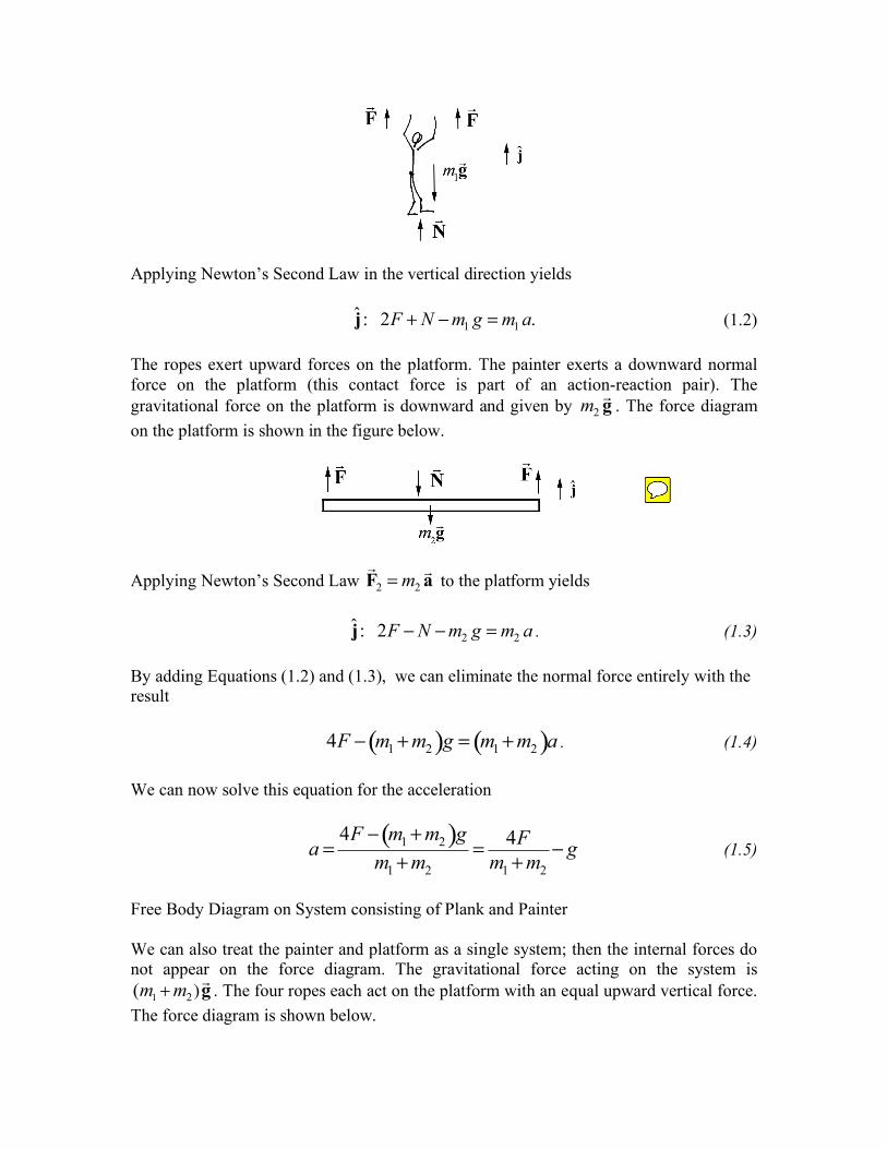
The ropes exert upward forces on the platform. The painter exerts a downward normal force on the platform (this contact force is part of an action-reaction pair). The !gravitational force on the platform is downward and given by m2 g . The force diagram on the platform is shown in the figure below.
! !Applying Newton’s Second Law F2 = m2 a to the platform yields
j: 2F ! N ! m g = m a . (1.3)2 2
By adding Equations (1.2) and (1.3), we can eliminate the normal force entirely with the result
4F ! (m + m )g = (m + m )a . (1.4)1 2 1 2
We can now solve this equation for the acceleration
4F ! (m1 + m2 )g 4F a = = ! g (1.5)m + m m + m1 2 1 2
Free Body Diagram on System consisting of Plank and Painter
We can also treat the painter and platform as a single system; then the internal forces do not appear on the force diagram. The gravitational force acting on the system is
2) !(m1 + m g . The four ropes each act on the platform with an equal upward vertical force.
The force diagram is shown below.
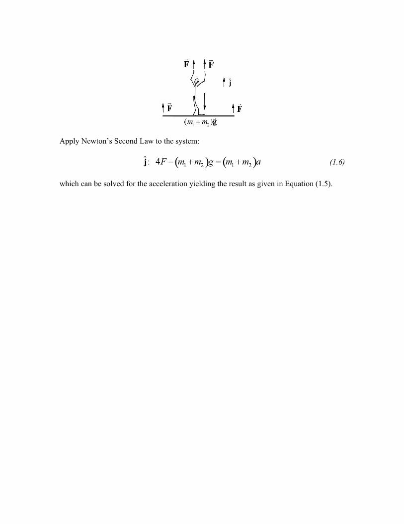
Apply Newton’s Second Law to the system:
j: 4F ! (m + m )g = (m + m )a (1.6)1 2 1 2
which can be solved for the acceleration yielding the result as given in Equation (1.5).
Problem 2: Towing a Sled
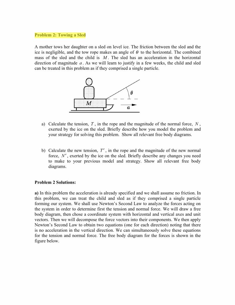
A mother tows her daughter on a sled on level ice. The friction between the sled and the ice is negligible, and the tow rope makes an angle of ! to the horizontal. The combined mass of the sled and the child is M . The sled has an acceleration in the horizontal direction of magnitude a . As we will learn to justify in a few weeks, the child and sled can be treated in this problem as if they comprised a single particle.
a) Calculate the tension, T , in the rope and the magnitude of the normal force, N , exerted by the ice on the sled. Briefly describe how you model the problem and your strategy for solving this problem. Show all relevant free body diagrams.
b) Calculate the new tension, T ! , in the rope and the magnitude of the new normal force, N ! , exerted by the ice on the sled. Briefly describe any changes you need to make to your previous model and strategy. Show all relevant free body diagrams.
Problem 2 Solutions:
a) In this problem the acceleration is already specified and we shall assume no friction. In this problem, we can treat the child and sled as if they comprised a single particle forming our system. We shall use Newton’s Second Law to analyze the forces acting on the system in order to determine first the tension and normal force. We will draw a free body diagram, then chose a coordinate system with horizontal and vertical axes and unit vectors. Then we will decompose the force vectors into their components. We then apply Newton’s Second Law to obtain two equations (one for each direction) noting that there is no acceleration in the vertical direction. We can simultaneously solve these equations for the tension and normal force. The free body diagram for the forces is shown in the figure below.
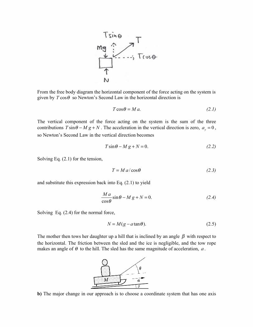
From the free body diagram the horizontal component of the force acting on the system is given by T cos! so Newton’s Second Law in the horizontal direction is
T cos ! = M a . (2.1)
The vertical component of the force acting on the system is the sum of the three contributions T sin ! " M g + N . The acceleration in the vertical direction is zero, ay = 0 , so Newton’s Second Law in the vertical direction becomes
T sin ! " M g + N = 0. (2.2)
Solving Eq. (2.1) for the tension,
T = M a / cos ! (2.3)
and substitute this expression back into Eq. (2.1) to yield
M a sin ! " M g + N = 0. (2.4)
cos !
Solving Eq. (2.4) for the normal force,
N = ( " a tan M g ! ). (2.5)
The mother then tows her daughter up a hill that is inclined by an angle ! with respect to the horizontal. The friction between the sled and the ice is negligible, and the tow rope makes an angle of ! to the hill. The sled has the same magnitude of acceleration, a .
b) The major change in our approach is to choose a coordinate system that has one axis
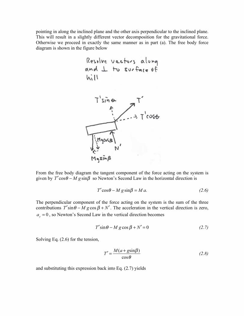
pointing in along the inclined plane and the other axis perpendicular to the inclined plane. This will result in a slightly different vector decomposition for the gravitational force. Otherwise we proceed in exactly the same manner as in part (a). The free body force diagram is shown in the figure below
From the free body diagram the tangent component of the force acting on the system is given by T #cos ! $ M g sin " so Newton’s Second Law in the horizontal direction is
T #cos ! $ M g sin " = M a . (2.6)
The perpendicular component of the force acting on the system is the sum of the three contributions T #sin ! $ M g cos " + N # . The acceleration in the vertical direction is zero, ay = 0 , so Newton’s Second Law in the vertical direction becomes
T #sin ! $ M g cos " + N # = 0 (2.7)
Solving Eq. (2.6) for the tension,
M (a + gsin ! )T # = (2.8)cos "
and substituting this expression back into Eq. (2.7) yields
( + gsin !M a ) sin " $ Mg cos ! + N # = 0. (2.9)
cos "
Solving Eq. (2.9) for the normal force,
M g ) tan " ). N # = ( cos ! $ (a + gsin ! (2.10)
Review/Check: When ! = 0 , Eq. (2.10) becomes N M g # a tan ! ) in agreement with " = ( Eq. (2.5). Also when ! = 0 , Eq. (2.8) becomes T " = Ma / cos ! in agreement with Eq. (2.3).

Problem 3:
A particle of mass m enters a region horizontally at time t = 0 with speed v0 midway between two plates that are separated by a distance h as shown in the figure. The particle is acting on by both gravity and by a time varying force that points upward and has magnitude
! F = bt
where b is a positive constant that is sufficiently large such that the particle hits the top plate without ever touching the bottom plate.
a) Sketch the motion of the particle.
b) How long does it take for the particle to reach its lowest point?
c) What is the minimum possible value of b such that the particle does not hit the lower plate?
Problem 3 Solutions:
Initially only the gravitational force acts on the object but as the particle starts to move, the vertically upward force grows linearly in time. This means that the particle will start to move both forward and downward but will eventually slow reach a lowest point and then start to move forward and upwards until it hits the plate. A sketch of the motion is shown in Figure 4.1

Figure 4.1 The lowest point in the orbit is reached when the vertical-component of the velocity is zero. The free body diagram for the forces acting on the object are shown in Figure 4.2a. We choose a coordinate system so the origin is located at the point of entry midway between the plates and positive y-axis points upwards (Figure 4.2b).
Figure 4.2a Figure 4.2b
Since the upward force grows linearly in time, the y-component of the acceleration must also increase linearly in time. We can integrate the y-component of the acceleration to find the y-component of the velocity and then integrate again to find the y-component of the position. This provides a model for the non-uniform motion. From our two equations we can determine the time interval, tb , it takes to reach the lowest point of the path when y-component of the velocity is zero, v ( ) = y tb 0 , and the minimum value of b such that the lowest point of the orbit satisfies y t( ) b = !h / 2 .
! !The component equations of motion corresponding to Newton’s Second Law, F = ma , are in the y-direction:
j : bt ! mg = ma y . (3.1)
Thus the vertical acceleration is b a = t ! g (3.2)y m
and the x-direction:
i : 0 = ma x . (3.3) Thus the vertical acceleration is
b a = t ! g (3.4)y m
and the horizontal acceleration is zero: ax = 0 . (3.5)
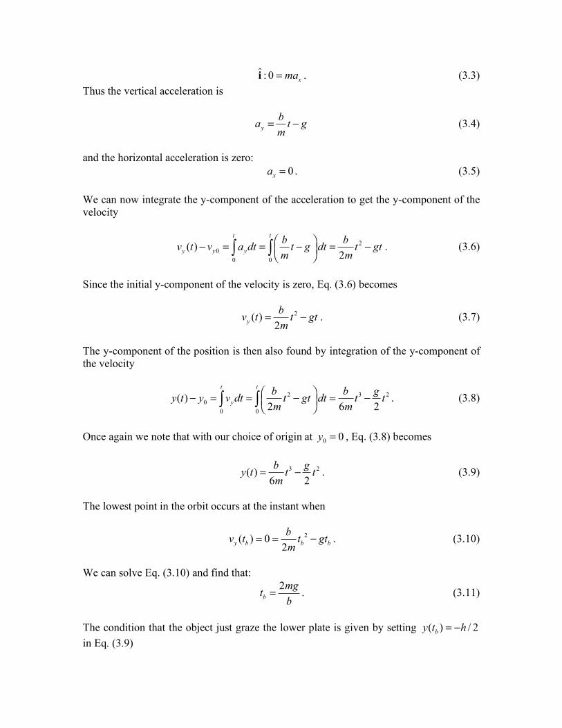
We can now integrate the y-component of the acceleration to get the y-component of the velocity
t t ! b " b 2t # gt . (3.6)v ( ) t # vy0 = a dt = $ t # g dt = y ( y ( %m ' 2m0 0 &
Since the initial y-component of the velocity is zero, Eq. (3.6) becomes
b 2v ( ) t = t ! gt . (3.7)y 2m
The y-component of the position is then also found by integration of the y-component of the velocity
t t b 2 " b g 2t . (3.8)y t ( ) # y = v dt = t # gt % dt = t3 #0 ( y ( !$ 0 0 & 2m ' 6m 2
Once again we note that with our choice of origin at y0 = 0 , Eq. (3.8) becomes
b 3 g 2y t ( ) = t ! t . (3.9)6m 2
The lowest point in the orbit occurs at the instant when
b 2vy ( ) tb = 0 = tb ! gt b . (3.10)2m
We can solve Eq. (3.10) and find that: 2mg t = . (3.11)b b
The condition that the object just graze the lower plate is given by setting y t( ) b = !h / 2 in Eq. (3.9)
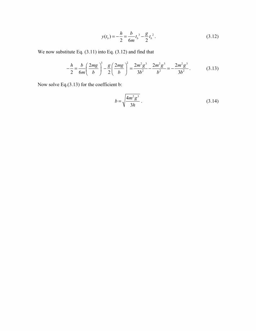
h b gy t ( ) = ! = tb 3 ! tb
2 . (3.12)b 2 6m 2
We now substitute Eq. (3.11) into Eq. (3.12) and find that
2 3 2 3 2 3
# h b ! 2mg "
3 g ! 2mg "2 2m g #
2m g 2m g = # = = # . (3.13)$ % $ % 2 2 22 6m & b ' 2 & b ' 3b b 3b
Now solve Eq.(3.13) for the coefficient b:
. (3.14) 2 34 3 m g b h
=
Problem 4: Emergency Landing
An airliner made an emergency landing at the Los Angeles airport with its nose wheel locked in a position perpendicular to its normal rolling position. The horizontal component of the plane’s velocity at touchdown is an unknown quantity vhoriz,0 . The forces acting to stop the airliner arose from friction due to the nose wheel and the braking effort of the engine in reverse thrust mode. The sum of horizontal forces can be modeled as
F ( ) t = !F + Bt (4.1)horiz 0
from touchdown at t = 0 until the plane comes to rest at t = ts . Assume the mass of the plane is m . The point of this problem is to figure how far the plane traveled from touchdown until it came to a stop. Express your answer in terms of the known quantities F0 , B, ts , m but not in terms of vhoriz,0 .
(a) Explain how you will model this problem and your strategy for solving it. Also include graphs of the horizontal position, horizontal component of the velocity, and horizontal component of the acceleration as functions of time.
(b) How far did the plane travel from touchdown until it came to a stop?
Problem 4 Solutions:
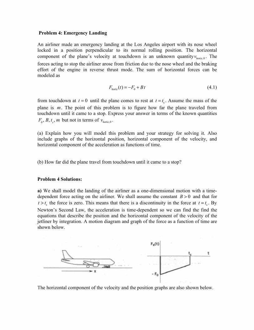
a) We shall model the landing of the airliner as a one-dimensional motion with a time-dependent force acting on the airliner. We shall assume the constant B > 0 and that for t > ts the force is zero. This means that there is a discontinuity in the force at t = ts . By Newton’s Second Law, the acceleration is time-dependent so we can find the find the equations that describe the position and the horizontal component of the velocity of the jetliner by integration. A motion diagram and graph of the force as a function of time are shown below.
The horizontal component of the velocity and the position graphs are also shown below.
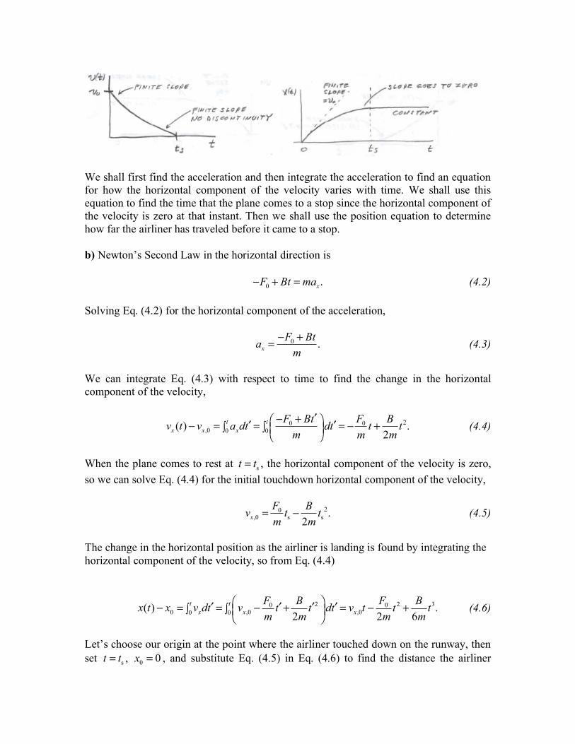
We shall first find the acceleration and then integrate the acceleration to find an equation for how the horizontal component of the velocity varies with time. We shall use this equation to find the time that the plane comes to a stop since the horizontal component of the velocity is zero at that instant. Then we shall use the position equation to determine how far the airliner has traveled before it came to a stop.
b) Newton’s Second Law in the horizontal direction is
!F0 + Bt = ma x. (4.2)
Solving Eq. (4.2) for the horizontal component of the acceleration,
!F + Bt ax = 0 . (4.3)
m
We can integrate Eq. (4.3) with respect to time to find the change in the horizontal component of the velocity,
t t # "F0 + Bt ! $ F0 B 2v ( ) t " v = a dt ! = dt ! = " t + t . (4.4)x x,0 %0 x %0 & ' ( m ) m 2m
When the plane comes to rest at t = ts , the horizontal component of the velocity is zero, so we can solve Eq. (4.4) for the initial touchdown horizontal component of the velocity,
v = F B
t 2. (4.5)0 t !x,0 m s 2m s
The change in the horizontal position as the airliner is landing is found by integrating the horizontal component of the velocity, so from Eq. (4.4)
t t ! F0 B 2 " F0 2 B 3( ) $ %0 v dt #x t x0 = x = %0 & vx,0 $ t# + t# dt # = vx,0 t $ t + t . (4.6)' ( m 2m ) 2m 6m
Let’s choose our origin at the point where the airliner touched down on the runway, then set t = ts , x0 = 0 , and substitute Eq. (4.5) in Eq. (4.6) to find the distance the airliner
traveled before it came to a stop,
F B 3 F0 2 B 3 F0 2 Bx t ( ) s = 0 ts
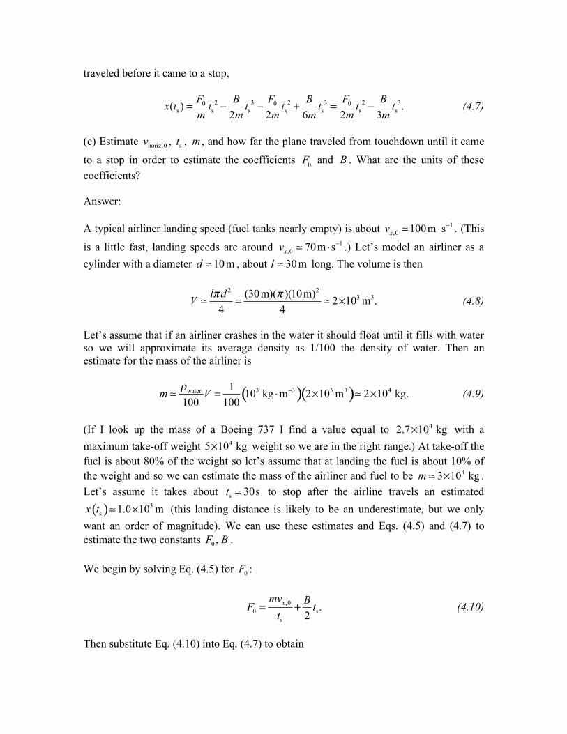
2 ! ! + = ! ts3. (4.7)ts ts ts tsm 2m 2m 6m 2m 3m
(c) Estimate vhoriz,0 , ts , m , and how far the plane traveled from touchdown until it came
to a stop in order to estimate the coefficients F0 and B . What are the units of these coefficients?
Answer:
A typical airliner landing speed (fuel tanks nearly empty) is about vx,0 ! 100m s " !1 . (This
is a little fast, landing speeds are around vx,0 ! 70m s !1 .) Let’s model an airliner as a " cylinder with a diameter d ! 10m , about l ! 30m long. The volume is then
l! 2 (30m)( )(10m) 2d ! 3 3V ! = ! 2"10 m . (4.8)4 4
Let’s assume that if an airliner crashes in the water it should float until it fills with water so we will approximate its average density as 1/100 the density of water. Then an estimate for the mass of the airliner is
! 1 3 "3 3 3 4water m ! V = (10 kg m )( 2$10 m )! 2$10 kg. (4.9)# 100 100
4(If I look up the mass of a Boeing 737 I find a value equal to 2.7!10 kg with a maximum take-off weight 5!10 4 kg weight so we are in the right range.) At take-off the fuel is about 80% of the weight so let’s assume that at landing the fuel is about 10% of the weight and so we can estimate the mass of the airliner and fuel to be m ! 3 104! kg . Let’s assume it takes about ts ! 30s to stop after the airline travels an estimated
3x t ( ) ! 1.0 !10 m (this landing distance is likely to be an underestimate, but we only s
want an order of magnitude). We can use these estimates and Eqs. (4.5) and (4.7) to estimate the two constants F0 , B .
We begin by solving Eq. (4.5) for F0 :
mv x,0 + B ts. (4.10)=F0 ts 2
Then substitute Eq. (4.10) into Eq. (4.7) to obtain
( ) ( )( )
( ) ( ) ( )
1 3
3
4 4
100m s 30s 1 10 m
2 1 1 30s
4 3 10 kg 3 3 10 kg
!" # !
$ % & '!& '# #( )
(4.13)
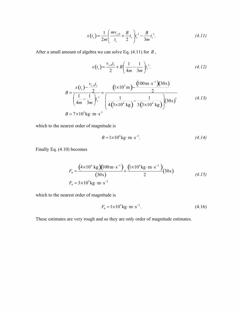
1 ! mv x,0 B " 2 B 3ts . (4.11)x t ( ) = + t t #$ s % ss 2m & ts 2 3m'
After a small amount of algebra we can solve Eq. (4.11) for B ,
vx,0 s t ! 1 1 " x t ( ) = + B # % ts3. (4.12)$s 2 & 4m 3m '
v tx,0 s x t ( ) s ! 2B = =
$ 1 1 % 3! t&( 4m 3m ') s
B ! 3 " -3 7#10 kg m s "
which to the nearest order of magnitude is
B " 1 10 kg m s # 4 $ $ !3. (4.14)
Finally Eq. (4.10) becomes
4 !1 4 !3) 1 10 kg m s # )(4"10 kg )( 100m s # ( " # F0 $ + (30s )(30s ) 2 (4.15)
5 !2 0 $ 3 10 kg # m s #F "
which to the nearest order of magnitude is
5 !2F0 " 1 10 kg m s # $ $ . (4.16)
These estimates are very rough and so they are only order of magnitude estimates.
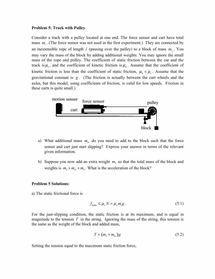
Problem 5: Track with Pulley
Consider a track with a pulley located at one end. The force sensor and cart have total mass m1 . (The force sensor was not used in the first experiment.) They are connected by an inextensible rope of length l (passing over the pulley) to a block of mass m2. . You may vary the mass of the block by adding additional weights. You may ignore the small mass of the rope and pulley. The coefficient of static friction between the car and the track is µs , and the coefficient of kinetic friction is µk . Assume that the coefficient of kinetic friction is less than the coefficient of static friction, µk < µs . Assume that the gravitational constant is g . (The friction is actually between the cart wheels and the axles, but this model, using coefficients of friction, is valid for low speeds. Friction in these carts is quite small.)
a) What additional mass mw do you need to add to the block such that the force sensor and cart just start slipping? Express your answer in terms of the relevant given information.
b) Suppose you now add an extra weight m3 so that the total mass of the block and weights is m + m + m . What is the acceleration of the block? 2 w 3
Problem 5 Solutions:
a) The static frictional force is
f ! µ N = µ m g . (5.1)static s s 1
For the just-slipping condition, the static friction is at its maximum, and is equal in magnitude to the tension T in the string. Ignoring the mass of the string, this tension is the same as the weight of the block and added mass,
T = (m + m )g (5.2)2 w
Setting the tension equal to the maximum static friction force,
( )2 w static, max s 1
w s 1 2.
m m g f m gm m m
µµ
+ = == !
(5.3)
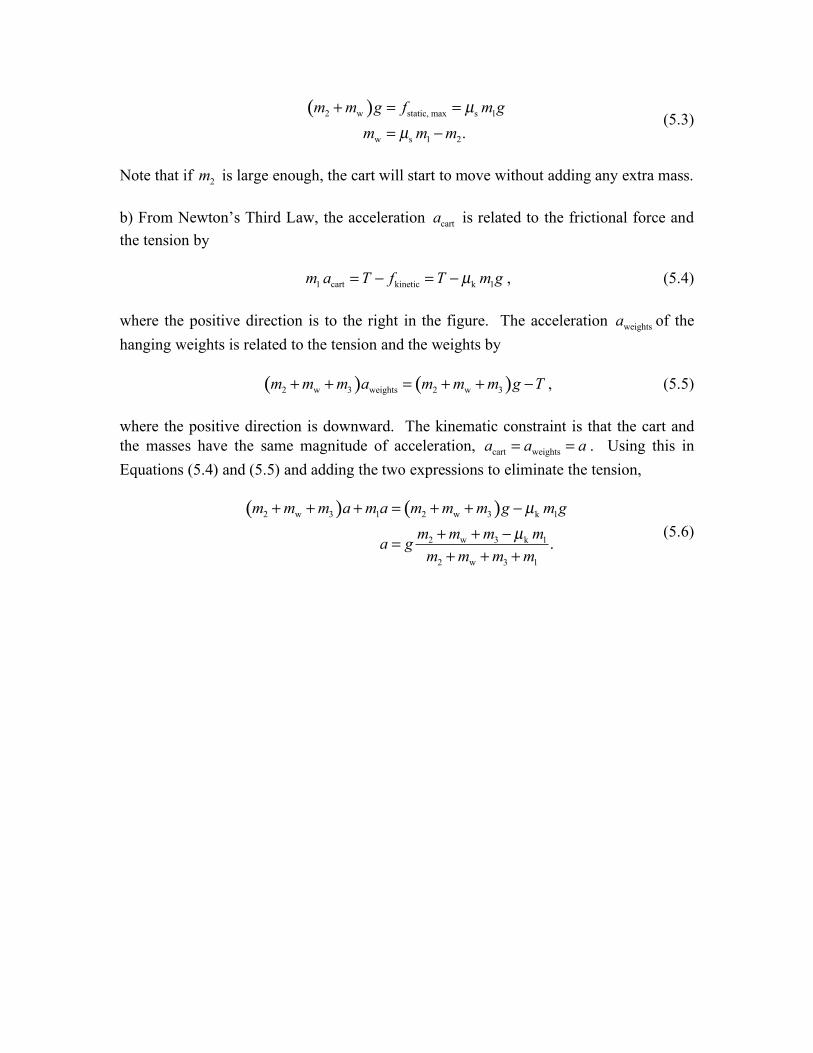
Note that if 2m is large enough, the cart will start to move without adding any extra mass. b) From Newton’s Third Law, the acceleration carta is related to the frictional force and the tension by 1 cart kinetic k 1m a T f T m gµ= ! = ! , (5.4) where the positive direction is to the right in the figure. The acceleration weightsa of the hanging weights is related to the tension and the weights by ( ) ( )2 w 3 weights 2 w 3m m m a m m m g T+ + = + + ! , (5.5) where the positive direction is downward. The kinematic constraint is that the cart and the masses have the same magnitude of acceleration, cart weightsa a a= = . Using this in Equations (5.4) and (5.5) and adding the two expressions to eliminate the tension,
( ) ( )2 w 3 1 2 w 3 k 1
2 w 3 k 1
2 w 3 1
.
m m m a m a m m m g m gm m m ma gm m m m
µµ
+ + + = + + !+ + !=+ + +
(5.6)
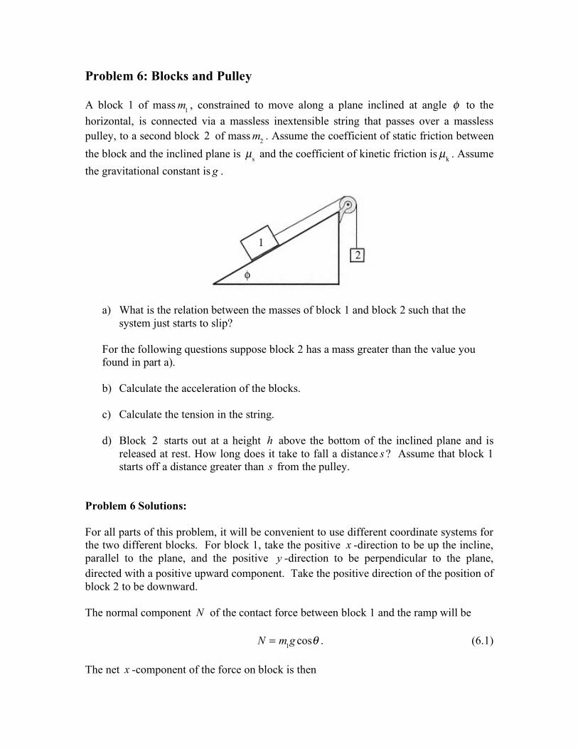
Problem 6: Blocks and Pulley A block 1 of mass m1 , constrained to move along a plane inclined at angle ! to the horizontal, is connected via a massless inextensible string that passes over a massless pulley, to a second block 2 of mass m2 . Assume the coefficient of static friction between the block and the inclined plane is µs and the coefficient of kinetic friction is µk . Assume the gravitational constant is g .
a) What is the relation between the masses of block 1 and block 2 such that the system just starts to slip?
For the following questions suppose block 2 has a mass greater than the value you found in part a). b) Calculate the acceleration of the blocks. c) Calculate the tension in the string.
d) Block 2 starts out at a height h above the bottom of the inclined plane and is
released at rest. How long does it take to fall a distance s ? Assume that block 1 starts off a distance greater than s from the pulley.
Problem 6 Solutions: For all parts of this problem, it will be convenient to use different coordinate systems for the two different blocks. For block 1, take the positive x -direction to be up the incline, parallel to the plane, and the positive y -direction to be perpendicular to the plane, directed with a positive upward component. Take the positive direction of the position of block 2 to be downward. The normal component N of the contact force between block 1 and the ramp will be N = m1g cos! . (6.1) The net x -component of the force on block is then
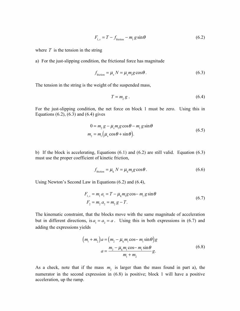
F1, x = T ! ffriction ! m1 g sin" (6.2)
where T is the tension in the string a) For the just-slipping condition, the frictional force has magnitude ffriction = µs N = µsm1g cos! . (6.3) The tension in the string is the weight of the suspended mass, T = m2 g . (6.4) For the just-slipping condition, the net force on block 1 must be zero. Using this in Equations (6.2), (6.3) and (6.4) gives
0 = m2 g ! µsm1g cos" ! m1 g sin"
m2 = m1 µs cos" + sin"( ). (6.5)
b) If the block is accelerating, Equations (6.1) and (6.2) are still valid. Equation (6.3) must use the proper coefficient of kinetic friction, ffriction = µk N = µkm1g cos! . (6.6) Using Newton’s Second Law in Equations (6.2) and (6.4),
F1, x = m1 a1 = T ! µkm1g cos! m1 g sin"
F2 = m2 a2 = m2 g ! T . (6.7)
The kinematic constraint, that the blocks move with the same magnitude of acceleration but in different directions, is a1 = a2 = a . Using this in both expressions in (6.7) and adding the expressions yields
m1 + m2( )a = m2 ! µkm1 cos! m1 sin"( )g
a =m2 ! µkm1 cos! m1 sin"
m1 + m2
g. (6.8)
As a check, note that if the mass m2 is larger than the mass found in part a), the numerator in the second expression in (6.8) is positive; block 1 will have a positive acceleration, up the ramp.
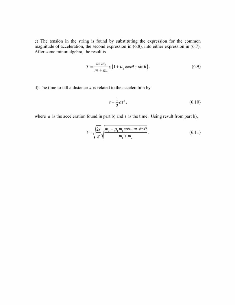
c) The tension in the string is found by substituting the expression for the common magnitude of acceleration, the second expression in (6.8), into either expression in (6.7). After some minor algebra, the result is
T =
m1 m2
m1+ m2
g 1+ µk cos! + sin!( ) . (6.9)
d) The time to fall a distance s is related to the acceleration by
s = 1
2at2 , (6.10)
where a is the acceleration found in part b) and t is the time. Using result from part b),
t = 2s
gm2 ! µkm1 cos! m1 sin"
m1 + m2
. (6.11)
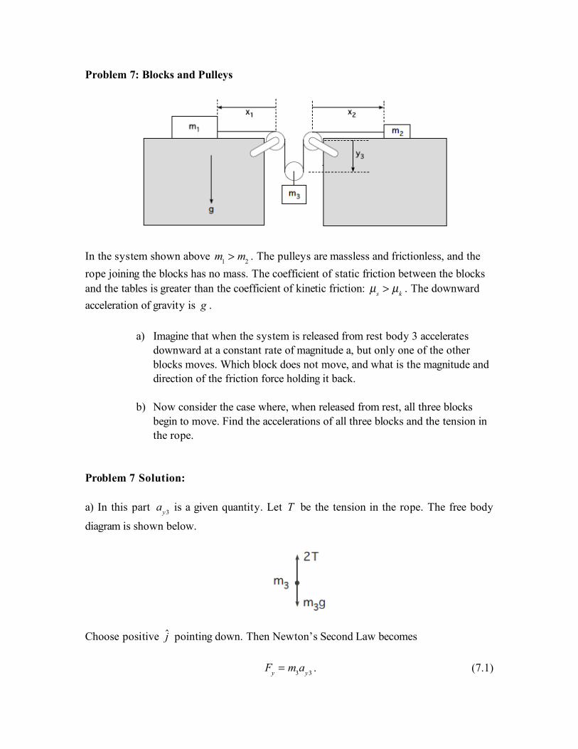
Problem 7: Blocks and Pulleys !
In the system shown above m1 > m2 . The pulleys are massless and frictionless, and the rope joining the blocks has no mass. The coefficient of static friction between the blocks and the tables is greater than the coefficient of kinetic friction: µs > µk . The downward acceleration of gravity is g .
a) Imagine that when the system is released from rest body 3 accelerates downward at a constant rate of magnitude a, but only one of the other blocks moves. Which block does not move, and what is the magnitude and direction of the friction force holding it back.
b) Now consider the case where, when released from rest, all three blocks
begin to move. Find the accelerations of all three blocks and the tension in the rope.
Problem 7 Solution: a) In this part
ay3 is a given quantity. Let T be the tension in the rope. The free body
diagram is shown below.
Choose positive j pointing down. Then Newton’s Second Law becomes
Fy = m3ay3 . (7.1)
m3g ! 2T = m3ay3 . (7.2) which we can solve for the tension
T =
12
m3(g ! ay3) . (7.3)
T exceeds the static friction force limit on one block but not the other which is given for the ith block by the expression
fs,max,i = µs Ni = µsmig . (7.4)
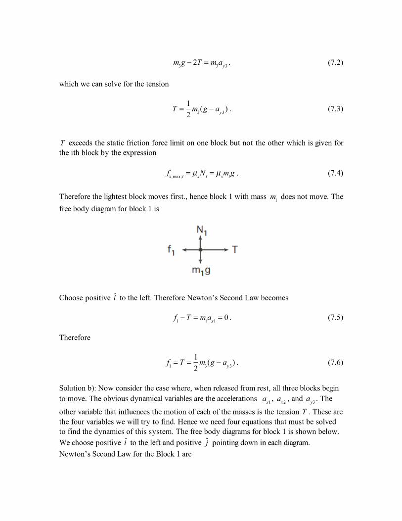
Therefore the lightest block moves first., hence block 1 with mass m1 does not move. The free body diagram for block 1 is
Choose positive i to the left. Therefore Newton’s Second Law becomes f1 ! T = m1ax1 = 0 . (7.5) Therefore
f1 = T =
12
m3(g ! ay3) . (7.6)
Solution b): Now consider the case where, when released from rest, all three blocks begin to move. The obvious dynamical variables are the accelerations ax1 , ax2 , and
ay3 . The
other variable that influences the motion of each of the masses is the tension T . These are the four variables we will try to find. Hence we need four equations that must be solved to find the dynamics of this system. The free body diagrams for block 1 is shown below. We choose positive i to the left and positive j pointing down in each diagram. Newton’s Second Law for the Block 1 are
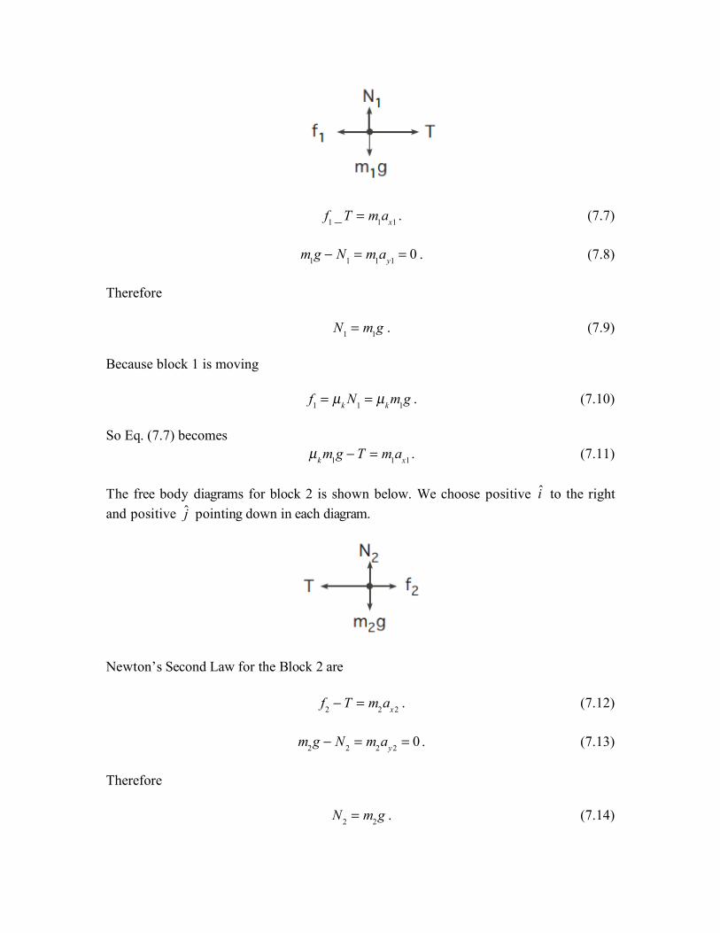
f1 _T = m1ax1 . (7.7)
m1g ! N1 = m1ay1 = 0 . (7.8) Therefore N1 = m1g . (7.9) Because block 1 is moving f1 = µk N1 = µk m1g . (7.10) So Eq. (7.7) becomes µk m1g ! T = m1ax1 . (7.11) The free body diagrams for block 2 is shown below. We choose positive i to the right and positive j pointing down in each diagram.
Newton’s Second Law for the Block 2 are f2 ! T = m2ax2 . (7.12)
m2g ! N2 = m2ay2 = 0 . (7.13) Therefore N2 = m2g . (7.14)
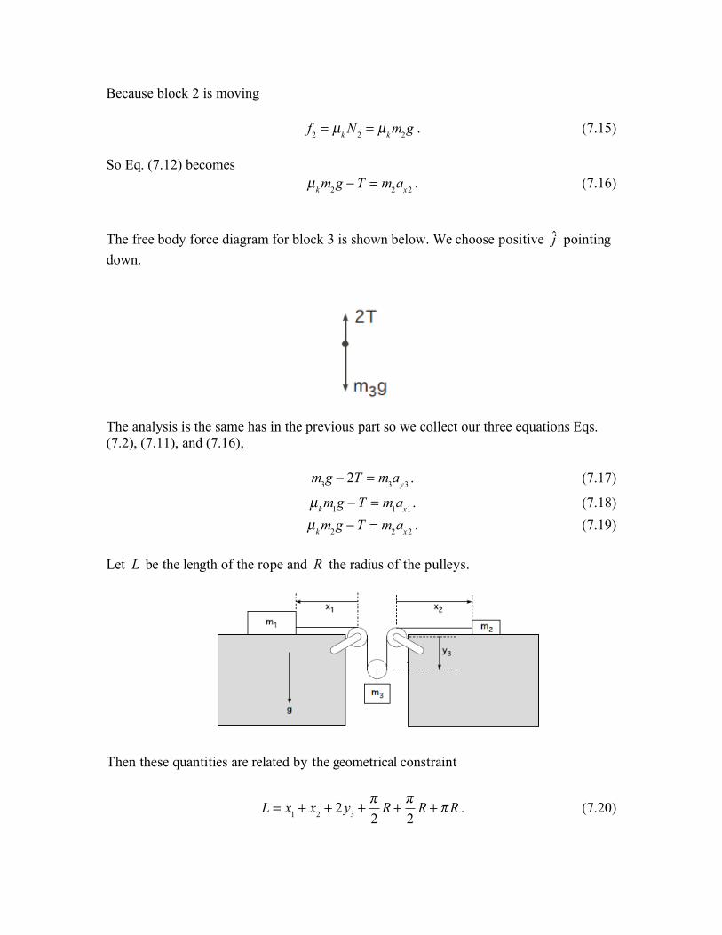
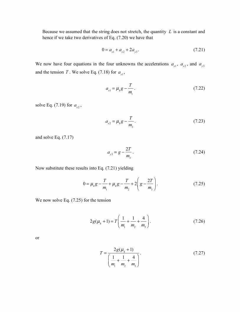
Because block 2 is moving f2 = µk N2 = µk m2g . (7.15) So Eq. (7.12) becomes µk m2g ! T = m2ax2 . (7.16) The free body force diagram for block 3 is shown below. We choose positive j pointing down.
The analysis is the same has in the previous part so we collect our three equations Eqs. (7.2), (7.11), and (7.16),
m3g ! 2T = m3ay3 . (7.17)
µk m1g ! T = m1ax1 . (7.18) µk m2g ! T = m2ax2 . (7.19) Let L be the length of the rope and R the radius of the pulleys.
Then these quantities are related by the geometrical constraint
L = x1 + x2 + 2y3 +
!2
R +!2
R + !R . (7.20)
Because we assumed that the string does not stretch, the quantity L is a constant and hence if we take two derivatives of Eq. (7.20) we have that
0 = ax1 + ax2 + 2ay3 . (7.21)
We now have four equations in the four unknowns the accelerations ax1 , ax2 , and
ay3
and the tension T . We solve Eq. (7.18) for ax1 ,
ax1 = µk g !
Tm1
. (7.22)
solve Eq. (7.19) for ax2 ,
ax2 = µk g !
Tm2
. (7.23)
and solve Eq. (7.17)
ay3 = g !
2Tm3
. (7.24)
Now substitute these results into Eq. (7.21) yielding
0 = µk g !
Tm1
+ µk g !Tm2
+ 2 g !2Tm3
"
#$%
&'. (7.25)
We now solve Eq. (7.25) for the tension
2g(µk +1) = T 1
m1
+1
m2
+4m3
!
"#$
%&. (7.26)
or
T =2g(µk +1)
1m1
+ 1m2
+ 4m3
!
"#$
%&
. (7.27)

We now solve for the accelerations. Eq. (7.22) becomes
ax1 = µk g !2g(µk +1)
1+m1
m2
+4m1
m3
"
#$%
&'
. (7.28)
solve Eq. (7.23) for ax2 ,
ax2 = µk g !2g(µk +1)m2
m1
+1+ 4m3
"
#$%
&'
. (7.29)
and solve Eq. (7.17) for
ay3 ,
ay3 = g !4g(µk +1)m3
m1
+m3
m2
+ 4"
#$%
&'
. (7.30)
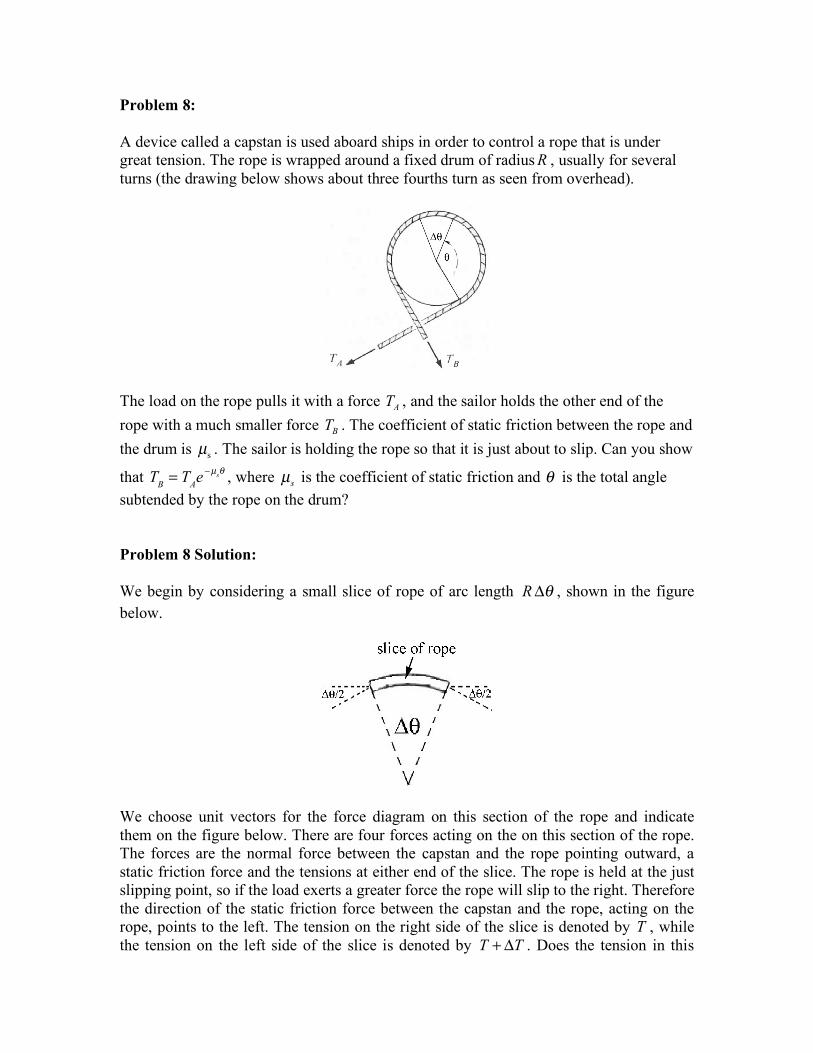
Problem 8: A device called a capstan is used aboard ships in order to control a rope that is under great tension. The rope is wrapped around a fixed drum of radiusR , usually for several turns (the drawing below shows about three fourths turn as seen from overhead).
The load on the rope pulls it with a force AT , and the sailor holds the other end of the rope with a much smaller force BT . The coefficient of static friction between the rope and the drum is sµ . The sailor is holding the rope so that it is just about to slip. Can you show
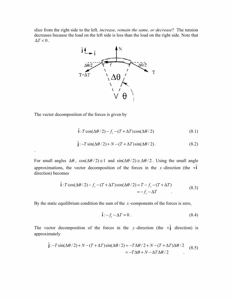
that TB = TAe !µs" , where sµ is the coefficient of static friction and ! is the total angle subtended by the rope on the drum? Problem 8 Solution: We begin by considering a small slice of rope of arc length R !" , shown in the figure below.
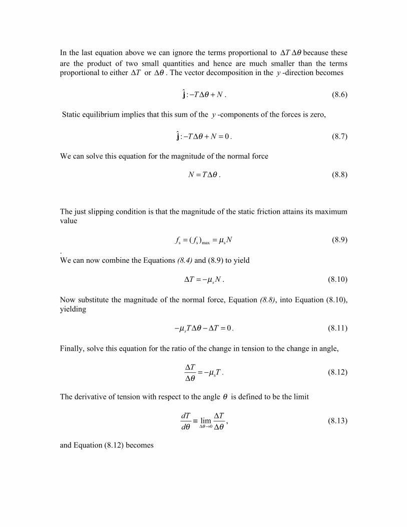
We choose unit vectors for the force diagram on this section of the rope and indicate them on the figure below. There are four forces acting on the on this section of the rope. The forces are the normal force between the capstan and the rope pointing outward, a static friction force and the tensions at either end of the slice. The rope is held at the just slipping point, so if the load exerts a greater force the rope will slip to the right. Therefore the direction of the static friction force between the capstan and the rope, acting on the rope, points to the left. The tension on the right side of the slice is denoted by T , while the tension on the left side of the slice is denoted by T T+ ! . Does the tension in this
slice from the right side to the left, increase, remain the same, or decrease? The tension decreases because the load on the left side is less than the load on the right side. Note that
0T! < .
The vector decomposition of the forces is given by ˆ : cos( / 2) ( ) cos( / 2)sT f T T! !" # # + " "i (8.1) ˆ : sin( / 2) ( )sin( / 2)T N T T! !" # + " + # #j . (8.2) . For small angles !" , cos( / 2) 1!" # and sin( / 2) / 2! !" # " . Using the small angle approximations, the vector decomposition of the forces in the x -direction (the ˆ+i direction) becomes
ˆ : cos( / 2) ( ) cos( / 2) ( )
.s s
s
T f T T T f T Tf T
! !" # # + " " # # + "= # #"
i ! (8.3)
By the static equilibrium condition the sum of the x -components of the forces is zero, s
ˆ : 0f T! !" =i . (8.4) The vector decomposition of the forces in the y -direction (the ˆ+j direction) is approximately
ˆ : sin( / 2) ( )sin( / 2) / 2 ( ) / 2
/ 2 .T N T T T N T T
T N T! ! ! !
! !" # + " + # # " # + " + # #
= " # + "# #j ! (8.5)
In the last equation above we can ignore the terms proportional to T !" " because these are the product of two small quantities and hence are much smaller than the terms proportional to either T! or !" . The vector decomposition in the y -direction becomes ˆ : T N!" # +j . (8.6) Static equilibrium implies that this sum of the y -components of the forces is zero, ˆ : 0T N!" # + =j . (8.7) We can solve this equation for the magnitude of the normal force N T != " . (8.8) The just slipping condition is that the magnitude of the static friction attains its maximum value s s max s( )f f Nµ= = (8.9) . We can now combine the Equations (8.4) and (8.9) to yield sT Nµ! = " . (8.10) Now substitute the magnitude of the normal force, Equation (8.8), into Equation (8.10), yielding 0sT Tµ !" # "# = . (8.11) Finally, solve this equation for the ratio of the change in tension to the change in angle,
sT Tµ!
" = #"
. (8.12)
The derivative of tension with respect to the angle ! is defined to be the limit
0
limdT Td !! !" #
"$"
, (8.13)
and Equation (8.12) becomes
sdT Td
µ!= " . (8.14)
This is an example of a first order linear differential equation that shows that the rate of change of tension with respect to the angle ! is proportional to the negative of the tension at that angle ! . This equation can be solved by integration using the technique of separation of variables. We first rewrite Equation (8.14) as
sdT dT
µ != " . (8.15)
Integrate both sides, noting that when 0! = , the tension is equal to force of the load AT , and when angle ,A B! != the tension is equal to the force BT the sailor applies to the rope,
,
0
A BB
A
T T
sT T
dT dT
! !
!
µ !==
= =
= "# # . (8.16)
The result of the integration is
,ln Bs A B
A
TT
µ !" #
= $% &' (
. (8.17)
Note that the exponential of the natural logarithm
exp ln B B
A A
T TT T
! "! "=# $# $# $% &% &
, (8.18)
so exponentiating both sides of Equation (8.17) yields
s ,A BB
A
T eT
µ !"= ; (8.19)
the tension decreases exponentially, s ,A B
B AT T e µ !"= , (8.20) We will also measure the tension in a rope that is wrapped around a knob in Experiment 2b where we will be able to test this model for how the tension in the rope varies as a function of the angle that the rope is wrapped around the knob. Since the tension decreases exponentially, the sailor need only apply a small force to prevent the rope from slipping.
MIT OpenCourseWare http://ocw.mit.edu 8.01SC Physics I: Classical Mechanics For information about citing these materials or our Terms of Use, visit: http://ocw.mit.edu/terms.