Embed Size (px)
Citation preview
Mission Support Alliance
Statement of Work
For
General Materials or Services
Title: Develop Design for the replacement of the Air-Cooled Scroll Chillers of HAMMER
Administrative Building Date: 4/10/2019 Revision Number: 0.0
1.0 INTRODUCTION / BACKGROUND
HAMMER Administrative Building 6091 has a central air handler unit that distributes air
conditioning and ventilation throughout ductwork to individual offices and classrooms.
Chilled water and hot water supply each cooling and heating coils of the central air handler
unit and air terminal units by two Trane 60 ton HVAC chillers and two water-heating
boilers. The HVAC Chillers are located outside the mechanical room and the Force-draft
Water Heating Boilers are located inside the mechanical room of HAMMER
Administrative Building 6091. The system contains a minimum of 35% glycol delivered
from the glycol make-up tank.
The HVAC system of HAMMER Administrative Building is controlled by Johnson
Control Metasys Automation system. Metasys is an off the shelf distributed control
software/hardware package that controls HVAC equipment.
2.0 OBJECTIVE
The objective of this Statement of Work (SOW) is to request engineering service to prepare
the design, calculation(s), provide engineering support during construction, and prepare as-
built drawings after completion for the construction for replacing of two HVAC Chillers
at HAMMER Administration Building 6091.
HVAC equipment: 60-tons Air Cooled Scroll chiller manufacturer: TRANE
Currently installed model number: CGAE0604ADA1ETAHRW
Proposed replacement Model number: CGAM060F* with the following description below:
Mission Support Alliance
Page 2 of 15
Unit type: High efficiency
Agency listing: UL listed
Unit application: High ambient (32 -1250F/0 - 520C)
Refrigerant isolation valves
Seismic to International Building Code (IBC)
Freeze protection.
Insulation: Factory insulation – All cold parts
Full factory refrigerant charge (R-410A)
Evaporator: Standard cooling (42 to 650 F)
Condenser fin material: Lanced aluminum
No condenser heat recovery
Starter type: Across the line starter/Direct on line
Power line connection type: Terminal block
Remote interface: BACNet Interface
External chilled water and demand limit set point: 2-10V dc
With percentage capacity
Programmable Relays
Pump type: no pump and contactors
No pump control.
Default A short circuit rating
Installation accessories: Elastomeric isolators
Sound attenuator: super quiet.
Appearance: Architectural louvered panel
Shipping package: No skid
Performance test with report
3.0 DESCRIPTION OF WORK – SPECIFIC
3.1 Task 1: The subcontractor shall provide all the designs in Facility Modification
Package (FMP) format to include, but not be limited to the following:
Design criteria used during the performance of the design tasks.
Demolition of two existing Trane air-cooled scroll chillers.
Demolition of existing four-inch and six-inch piping, valves and fittings outside
mechanical room as necessary.
Modify the existing concrete pads to fit with two new air-cooled scroll chillers including
concrete mix design, rebar reinforcement, and grading.
Perform pressure drop, flow rate, pipe support and pipe stress calculations as necessary.
Installation of two new air-cooled scroll chillers including new pipe, fittings and valves.
Connect the existing chilled water piping to the new chilled water piping.
Mission Support Alliance
Page 3 of 15
Provide isometric drawings for new chilled water pipe connects to existing chilled water
pipe (Bill of Material shall be included).
Provide necessary electrical power to operate two new air-cooled scroll chillers.
Modify the control drawings as necessary.
Equipment operation testing is not including in this SOW.
There will be two design submittals set as defined below:
o 60% design submittal to include but not be limited to:
Complete preliminary Mechanical drawings including slab plan, piping layout,
HVAC equipment schedule, P&ID, etc.
Complete preliminary Civil drawings including grading and utility run, etc.
Completed preliminary Electrical drawing including one line diagrams, panel
schedule, control drawings etc.
Complete preliminary calculations such as pressure drop, flow rate, pipe stress
Complete preliminary specification listing including as a minimum grading,
excavation (if required) concrete, HVAC, electrical, etc.
o 90% design submittal shall be in Facility Modification Format Form ready to be
released into the DMCS system. 90% design submittal shall be included but not be
limited to:
Final Mechanical drawings including slab drawings, piping layout, HVAC
equipment schedule, HVAC equipment layout etc.
Final Civil drawings including site grading plan and utility runs.
Final Electrical drawings including one line diagram, panel schedule, control
drawings etc.
Final specification listing including as a minimum grading, excavation (if
required), concrete, HVAC, electrical, etc.
Final verified calculations.
o 100% design submittal
This design submittal will resubmit the 90% design with all MSA generated
comments incorporated.
3.2 Task 2: Provide engineering during construction support, to include dispositioning
Request for Clarifications (RCI’s) or equivalent, and providing design changes as
required. It is anticipated that there will be approximately 5 design submittals
requiring design engineering support during construction.
3.3. Task 3: Prepare As-Built drawings incorporating field redlines and any other
changes.
Mission Support Alliance
Page 4 of 15
4.0 REQUIREMENTS
4.1 General
Will work be performed on site: No
For any work performed on the Hanford Site or any MSA controlled facility, the provisions
of the On Site Services Special Provisions, will apply to Subcontractor personnel.
Employee Job Task Analysis (EJTA) in accordance with MSC-PRO-WP-11058 or
documentation explaining why an EJTA is not required.
4.2 Engineering Requirements
Engineering requirements applicable: Yes
Subcontractor shall assume the Codes and Standards listed in the following table are
applicable as noted.
Applicable Engineering Codes and Standards
Number Title
1. MSC-GD-ENG-11851 MSC Engineering Guidance
2. MSC-PRO-ENG-709 CAD and Drawing Development and Control Process for
Engineering Drawings
3. MSC-PRO-ENG-2001 Facility Modification Package Process
4. HNF-14660 Rev 4 Off-Site Vendor Direction for Preparation and Control of
Engineering Drawings
5. NFPA 70 -2017 National Electrical Code
6. NFPA 70E – 2018 Standard for Electrical Safety in the Workspace
8. NFPA 90A 2018 Standard for the Installation of Air Conditioning and
Ventilating Systems.
9. Washington State
Energy Codes – 2015
Washington State Energy Codes 2015
10. IMC 2015 International Mechanical Code 2015
11. NFPA 90B - 2018 Standard for the installation of Warm air Heating and Air-
Conditioning system.
12. ASHRAE 111 – 2008 Measurement, Testing, Adjusting and Balancing of Building
HVAC system.
13 ACI 318 - 14 Building Code Requirements for Structural Concrete and
Commentary.
Mission Support Alliance
Page 5 of 15
18 MSC-STD-ENG-097 MSC Engineering Design Codes, Standard and Site specific
Design parameters
19 ASME B31.5 - 2016 Refrigeration Piping and Heat Transfer Components
20 ASME B31.9 – 2017 Building Services Piping
21 MSC-STD-ENG-097 MSC Engineer Design Codes, Standard and Site Specific
Design Parameters.
22 MSC-PRO-ENG-8259 MSC Calculation Preparation and Issue
23 MSC-PRO-ENG-8258 Functional Requirement and Design Criteria
24 MSC-PRO-ENG-16406 Engineering Vendor Information Process
25 MSC-PRO-ENG-440 MSC Engineering Package Process
26 MSC-PRO-ENG-8017 As-Built Verification Process
27 MSC-PRO-ENG-8336 Design Verification
28 MSC-PRO-ENG-16406 Engineering Vendor Information (VI) Process
It is the Subcontractor’s responsibility to identify all applicable codes and standards that apply to
each requested support activity, unless identified by the Buyer. In addition to the codes and
standards listed above, the subcontractor may utilize the following drawings during the
development of the design:
H-6-13618-1 General HVAC Details I
H-6-13619-1: General HVAC Details II
H-6-13626-1: Single line diagrams
H-6-13628-1: Panel schedule I
H-6-13689-1: Administration Building HVAC equipment schedules
H-6-13690-1: Administration Building HVAC equipment schedules
H-6-13696-1: Administration Building HVAC plan
H-6-13697-1: Administration Building large scale mechanical room plan
H-6-13698-1: Administration Building HVAC sections
H-6-13699-1: Administration Building HVAC flow diagrams
H-6-13701-1: Administration Building HVAC control diagrams
H-6-13702-1: Administration Building HVAC control diagram II
4.3 Environment, Safety, & Health (ES&H) Requirements
The Subcontractor shall exercise a degree of care commensurate with the work and the
associated hazards. The Subcontractor shall ensure that management of safety and
environmental functions and activities is an integral and visible part of the Subcontractor’s
work planning and execution processes. The Subcontractor shall flow down safety and
Mission Support Alliance
Page 6 of 15
environmental requirements to the lowest tier Subcontractor performing work on the
Hanford site commensurate with the risk and complexity of the work.
All subcontractor and sub-tier employees shall have completed OSHA Hazard
Communication training that meets the requirements of MSC-PRO-WP-13299, Hazard
Communication. See MSC-PRO-WP-10468, Chemical Management Process, for more
information.
Buyer’s Safety and Health Procedures are available on the internet at
http://www.hanford.gov/pmm/page.cfm/Construction. The documents on this site are kept
current and are available for Subcontractors and lower-tier Subcontractor use.
Unique or specific requirements: No
4.4 Quality Assurance (QA) Requirements
Are quality assurance requirement applicable to this scope of work: Yes
The work activities for this Statement of Work has been designated as a Quality Level F -
Q Level 3 - GS
The Subcontractor shall have a Quality Assurance Program (QAP) and implementing procedures
that utilizes a national or international voluntary consensus standard such as ASME NQA-1, or
the ISO 9000 Series of Standards or equivalent that include the following requirements, as a
minimum:
1. Organizational structure, including a description of roles and responsibilities
2. QAP which describes the process to control items and activities
3. Indoctrination, training, and qualification and/or certification of project personnel
4. Design control, including design verification/validation, change control, and software
quality requirements to ensure software produces correct results
5. Implementing procedures and/or instructions that describe step by step activities
6. Document control to ensure only correct documents are being used
7. Corrective action management to identify and correct issues that lead to process
improvements
8. Quality records, which are protected from loss or deterioration and are submitted.
Mission Support Alliance
Page 7 of 15
The QAP document and implementing procedures are required to be reviewed, evaluated, and
approved by MSA Projects Quality Assurance Engineering Organization upon award of the
subcontract. The Subcontractor shall, during the performance of this Subcontract, submit
proposed changes to the QAP and implementing procedures to the Buyer/QAE/CS for review
and approval prior to implementation.
The Subcontractor shall be responsible for performing quality workmanship and shall conduct
the quality control measures necessary to ensure that all work confirms to referenced codes,
standards, and other requirements as defined by this SOW.
If the Subcontractor subcontracts any portion of this work scope to lower tier subcontractors, the
Subcontractor shall be responsible for the flow down of applicable portions of this SOW to their
lower-tier subcontractors, including engineering and quality assurance requirements, pertaining
to services and activities for which they are responsible.
All Subcontractor activities are subject to oversight by MSA’s QAE and/or Engineering
representative(s) at the Subcontractor’s facilities, including lower-tier facilities if applicable.
Access to the Subcontractor’s or lower-tier’s facilities shall be requested through the
Subcontractor’s contract representative and MSA’s CS. The visit may be performed jointly with
the Subcontractor.
The work activities for this statement of work shall be performed in accordance with the
following MSA Quality Assurance Program and Procedures, if provided below
Applicable Quality Assurance Standards
Number Title
1. MSC-PRO-QA-8635 Review and approval of Technical Documents
2. MSC-PRO-QA-3144 Supplier Quality Assurance Program Evaluation
3. MSC-GD-ENG-
33553
Engineering Implementation of the graded approach for
procurement of material and services.
4 MSC-OTHER-QA-
26661
MSA Quality Assurance Program Plan (QAPP)
Commercial Off the Shelf Software
NOTE: If the same COTS product is utilized for a range of calculations this documentation only
needs to be submitted once, but documents/calculations shall be traceable back to number 1
specified below and is subject to oversight activities.
1. Description of the COTS software including:
a. Manufacturer’s name and address
Mission Support Alliance
Page 8 of 15
b. COTS application’s title and version identifier
c. Operating system and hardware platform that will be used.
d. Manufacturer’s Technical Specifications or other published description of the
COTS
2. Standard data set(s) used to verify operation of the COTS application
a. Data sets shall cover each function or mode of operation, which will be used during the
performance of the work activities.
b. When the COTS application’s range of operation cannot be verified by a single data
set, the A/E shall submit, as a minimum, data sets covering the upper and lower thirds
of its range.
3. A/E shall notify MSA of any software errors related to COTS deliverables
4.6 Government Property
Government property is not required to be used by the Subcontractor for this effort.
5.0 PERSONNEL REQUIREMENTS
1. Training and Qualifications
Training
All calculations are to be performed by engineers having a minimum of a bachelor’s degree
in the appropriate engineering field.
Subcontractor shall ensure that its personnel meet and maintain the appropriate training,
qualification and certification requirements.
1. All Subcontractor personnel shall complete MSA General Employee Training
(MGET) (4-hour average per individual) or Hanford Site Orientation (HSO) (sent
to the Subcontractor at their location).
If subcontractor requires the use of ladders or scaffold access during construction or as-
building tasks, the training listed below will be required prior to performing those field
activities:
2. Fall Protection Hazards Training.
Qualifications
Subcontractor personnel performing engineering services shall have appropriate training,
experience, qualification and/or certification(s) to perform to work required by this task..
Provide a list of previous projects as it relates to the HVAC chiller replacement and control.
Mission Support Alliance
Page 9 of 15
All MSA engineering deliverables are to be “stamped” and approved by a degreed engineer
possessing a current State of Washington Professional Engineer License in the appropriate
field.
5.1 Security and Badging Requirements
The scope of work will not require access authorization (security clearance).
5.2 Work Location / Potential Access Requirements
Work will be performed off-site with the exception of limited meetings during
design/construction and performance of the as-building task.
5.3 Site Access and Work Hours
Hanford personnel at the Hanford Site work a standard 4/10 schedule. The standard work
week consist of ten (10) hours of work between 6:00 am and 4:30 pm, with one-half hour
designated as an unpaid period for lunch, Monday through Thursday.
Work performed outside normal operating hours shall be coordinated and/or approved
through the BTR and/or the Contract Specialist prior to performing the work.
6.0 MEETINGS
Subcontractor shall participate in all meetings as required by the Buyer’s Technical Representative
(BTR).
7.0 DELIVERABLES AND PERFORMANCE SCHEDULE REQUIREMENTS
7.1 Deliverables
Deliverables are required to be furnished by the Subcontractor. See Appendix A – Master
Submittal Register.
Request for Clarification/Information are to be provided to the Buyer’s Technical
Representative (BTR) using request for Clarification or Information form (A-6003-063)
If deliverables are required, the specific deliverables, dates for completion, reviews, etc.,
are as follows:
7.2 Schedule
Start Date: Within 7 working days of award contract
Completion Date: Construction Completion + 63 days
Mission Support Alliance
Page 10 of 15
8.0 SPECIAL REQUIREMENTS
8.1 Communication with Hanford Site Regulatory Agencies
Under no circumstances shall the subcontractor interact directly with regulatory agencies prior to
notifying and obtaining the concurrence of the Contract Specialist and the Buyer’s Technical
Representative.
8.2 Submittals:
If the SOW requires the submittal of Subcontractor Information, the following apply:
The following items shall be submitted to the Contract Specialist in accordance with the
instructions contained in the Attachment A, Submittal Register.
The Subcontractor submittals identified herein and summarized on the Submittal Register
shall be submitted by the Subcontractor using the Subcontractor Document Submittal Form
(CDSF)
See: http://www.hanford.gov/pmm/page.cfm/Construction.
Subcontractor information shall be submitted in either hard copy or electronic format (If
electronic, it must be viewable using either Microsoft® Windows®, Microsoft® Office, or
Adobe® Acrobat® software).
Configuration Management:
If there will be any configuration management requirements associated with this statement of
work, the selections below will apply:
If the Statement of Work requires the development or revision of Engineering
Drawings, the following applies:
o New or revised Engineering Drawings to be released into the MSA document
control system shall be prepared and entered in accordance with HNF-14660,
Offsite Subcontractor Instruction for Preparation and Control of Engineering
Drawings.
If the Statement of Work requires the development or revision of Technical Documents
(including Vendor submittals generated to specific site standards and or procedures for
site specific items or applications), the following applies:
o New or revised Technical Documents shall be prepared in accordance with
MSC-PRO-ENG-16406, Vendor Information Process.
Mission Support Alliance
Page 11 of 15
If the Statement of Work requires the development and submittal of a Design Analysis
or design calculation, the following applies:
o Design Analysis documentation shall include (1) through (6) below: (1)
definition of the objective of the analysis; (2) definition of analysis inputs and
their sources; (3) results of literature searches or other applicable background
data; (4) identification of assumptions and indication of those that must be
verified as the design proceeds; (5) identification of any computer calculation
including computer type, computer program (e.g., name), revision
identification, inputs, outputs, evidence of or reference to computer program
verification and the bases (or reference thereto) supporting application of the
computer program to the specific physical problem; (6) review and approval.
If the Statement of Work requires the submittal of Engineering Change Notices or Field
Change Notices, the following applies:
o New or revised Engineering Change Notices or Field Change Notices shall be
prepared and submitted in accordance with the BTR’s instruction.
Design Team Task Lead Expectations
o A single point of contact shall be established to fulfill the role of Task Lead
(e.g., the Subcontractor’s project manager)
Design Process
o The subcontractor shall develop design content in accordance with their
internal, qualified engineering process.
Design Interfaces
o Design interfaces, where present, shall be identified, documented, and
controlled in a specification or on a drawing and be uniquely identified.
Documentation
o Work produced as part of this SOW shall be documented and meet the
requirements and Standards listed in Section 4.2 and 3.0.
Design Review
o Each design product shall be checked, reviewed and approved internally by the
Subcontractor, prior to providing the design package to the Buyer for review,
comment, and subsequent approval.
As Built Process
Mission Support Alliance
Page 12 of 15
o The subcontractor shall have a documented as-built process as part of their
engineering program procedures that will ensure that as-building activities will
depict the post-installation physical facility conditions.
Reporting Administration
Include any status reports (e.g. cost and technical), status meetings, accrual submittals,
expectations for safety meeting attendance, and requirements for formatting of documents as
instructed by the BTR.
Meetings
General purpose of meetings is for the coordination, control, and direction of the Work. In addition
to meetings addressed by this Section, Subcontractor may be required by other Sections and other
Subcontract documents to conduct special-purpose meetings and various safety meetings and
briefings.
MSA will issue meeting notices and prepare an agenda and minutes for each meeting addressed in
this Section. When applicable, minutes will identify action items, assigned actionees, and due
dates.
KICKOFF MEETING - Before start of the Work, MSA will conduct a conference at a time
and Hanford Site location agreed to by Subcontractor and MSA. Invited attendees will
include MSA, Subcontractor, key lower tier subcontractors and others having an interest
in the Work. Purpose of the conference is the coordination of Work start up and
familiarization of project participants with the Work and worksite.
PROGRESS MEETINGS - MSA will conduct a progress meeting at time and Hanford Site
location determined by MSA. Invited attendees will include MSA, Subcontractor and key
subcontractors. At the progress meeting, Subcontractor shall submit a written report
showing actual man-hours expended versus planned and scheduled progress versus actual
progress giving details of Work completed in relation to the approved schedule, together
with a two (2) week "look ahead" which provides details of how the Work will be
completed.
The purpose of the meetings is the exchange of Work-related information.
Mission Support Alliance
Page 13 of 15
ATTACHMENT A
SUBMITTAL REGISTER
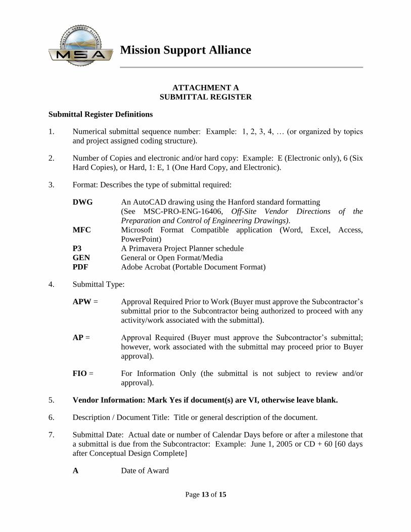
Submittal Register Definitions
1. Numerical submittal sequence number: Example: 1, 2, 3, 4, … (or organized by topics
and project assigned coding structure).
2. Number of Copies and electronic and/or hard copy: Example: E (Electronic only), 6 (Six
Hard Copies), or Hard, 1: E, 1 (One Hard Copy, and Electronic).
3. Format: Describes the type of submittal required:
DWG An AutoCAD drawing using the Hanford standard formatting
(See MSC-PRO-ENG-16406, Off-Site Vendor Directions of the
Preparation and Control of Engineering Drawings).
MFC Microsoft Format Compatible application (Word, Excel, Access,
PowerPoint)
P3 A Primavera Project Planner schedule
GEN General or Open Format/Media
PDF Adobe Acrobat (Portable Document Format)
4. Submittal Type:
APW = Approval Required Prior to Work (Buyer must approve the Subcontractor’s
submittal prior to the Subcontractor being authorized to proceed with any
activity/work associated with the submittal).
AP = Approval Required (Buyer must approve the Subcontractor’s submittal;
however, work associated with the submittal may proceed prior to Buyer
approval).
FIO = For Information Only (the submittal is not subject to review and/or
approval).
5. Vendor Information: Mark Yes if document(s) are VI, otherwise leave blank.
6. Description / Document Title: Title or general description of the document.
7. Submittal Date: Actual date or number of Calendar Days before or after a milestone that
a submittal is due from the Subcontractor: Example: June 1, 2005 or CD + 60 [60 days
after Conceptual Design Complete]
A Date of Award
Mission Support Alliance
Page 14 of 15
CD Conceptual Design Complete
PD Preliminary Design Complete
FD Final Design Complete
M Mobilization
SC Start of Construction
EC End of Construction
8. Buyer Review Time (Work Days): Example: 3 Days
9. Subcontract Reference: Cross reference to the Subcontract requirement that defines this
submittal: Example: SOW 3.1.2.
Mission Support Alliance
Page 15 of 15
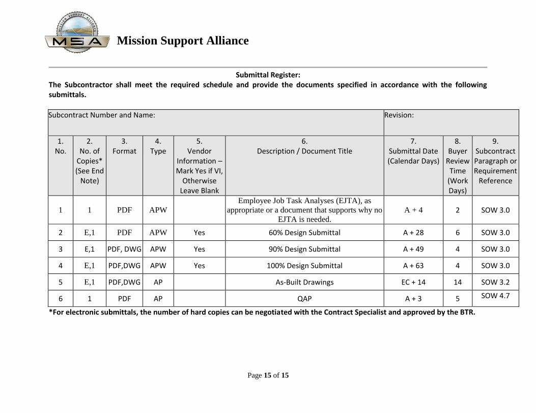
Submittal Register: The Subcontractor shall meet the required schedule and provide the documents specified in accordance with the following submittals.
Subcontract Number and Name: Revision:
1. No.
2. No. of
Copies* (See End
Note)
3. Format
4. Type
5. Vendor
Information – Mark Yes if VI,
Otherwise Leave Blank
6. Description / Document Title
7. Submittal Date (Calendar Days)
8. Buyer
Review Time
(Work Days)
9. Subcontract Paragraph or Requirement
Reference
1 1 PDF APW Employee Job Task Analyses (EJTA), as
appropriate or a document that supports why no
EJTA is needed.
A + 4 2 SOW 3.0
2 E,1 PDF APW Yes 60% Design Submittal A + 28 6 SOW 3.0
3 E,1 PDF, DWG APW Yes 90% Design Submittal A + 49 4 SOW 3.0
4 E,1 PDF,DWG APW Yes 100% Design Submittal A + 63 4 SOW 3.0
5 E,1 PDF,DWG AP As-Built Drawings EC + 14 14 SOW 3.2
6 1 PDF AP QAP A + 3 5 SOW 4.7
*For electronic submittals, the number of hard copies can be negotiated with the Contract Specialist and approved by the BTR.