Embed Size (px)
Citation preview

PRODUCTS AND SYSTEMSFOR ELECTRICAL INSTALLATIONS
AND INFORMATION NETWORKS
2007-2008CATALOGUE

256 257
PRODUCTS AND SYSTEMS FOR ELECTRICAL INSTALLATIONS AND INFORMATION NETWORKS
Industrialenclosuresandequipment
Marina cabinetsand enclosures- cabinets (p. 273)- enclosures (p. 275)
Heat regulation:- ventilators (p. 286)- exchangers (p. 288)- air-conditioners (p. 288)
N e w i n 2 0 0 7
Cabinets :- Atlantic- MarinaEnclosures :- Marina
Heat regulation
Cable glands
Flexible conduits
P. 266Atlantic and Marinaselection chart
P. 276Marina polyesterenclosuresIP 66 - IK 10
P. 280Common equipmentfor cabinets
P. 268Atlanticmetal cabinetsIP 55 - IK 10
P. 270Atlantic metalcabinets adjustedcharacteristicsIP 55 - IK 10
P. 261Atlantic industrialmetal boxes
P. 262Technicalcharacteristics
P. 286Naturalventilation,ventilators
P. 294Multi-entryplastic cableglands IP 66
P. 298Presentationof flexibleconduits
Industrialboxes
P. 258The right materialfor enclosures
P. 290Enclosures andheat regulationselection chart
P. 295Nickel platedbrass cable glandsIP 65
P. 288Exchangers,air-conditioners
P. 294Plastic cableglands IP 68
P. 300Polyamide flexibleconduits
P. 273Atlantic stainlesssteel cabinetsIP 66 - IK 10
P. 264Plastic industrialboxes
P. 265Technicalcharacteristics
P. 289Heating
P. 295Plastic cableglands IP 55
P. 304PVC and metalloplasticflexible conduits
P. 274Marina polyestercabinets
P. 291Technicalcharacteristics
P. 284Lockingaccessories
P. 285Fixingaccessories
NEW
NEW NEW
NEW
NEW
NEW
NEW
Flexible conduits- polyamide (p. 300)- PVC and metalloplastic(p. 304)

258
Stainless steel is suitable for the mostdemanding environments: depending on thetypes of corrosion encountered, Legrand offerstwo qualities of stainless steel, including 316 Lstainless steel, which is recommended for veryharsh environments (salting, offshore, etc.)
Steel is suitable for commercial andindustrial premises that have no specialrequirements, and no excessive corrosion
POLYESTER COATED STEEL
STAINLESS STEEL
For corrosive environments: fibreglass reinforced polyester resin
GLASS REINFORCED POLYESTER RESIN
■ Industrial environments, service areas, public buildings: Atlanticcabinet (p. 268)
■ Coast, petrochemicals, very harsh environments:Marina cabinets and enclosures (p. 274 to 276)
■ Laboratories, food processing industry, special hygienerequirements: stainless steel Atlantic cabinets (p. 273)
Cabinets and enclosures[A
TLAN
TIS,
MAR
INA
]
For each ambient environment, Legrand has the right enclosure for you,made of the appropriate material
The right materialfor your environment

259
cabinets and enclosures: the right material for your environment
■ Polyester coated steel: AtlanticFor industrial environments that have no special requirements,and no excessive corrosion IP 55 according to standard IEC EN 60529Hinges and pins of cabinets with high performance anti-corrosiontreatment
Resistance of the coating according to testsMechanical characteristics:– Adhesion (grid and adhesive tape) EN ISO 2409: class 0 to 1– Persoz hardness EN ISO 1522: 320’’– Bending on cylindrical mandrel EN ISO 1519: 6 mm, no cracks– Erichsen stamping EN ISO 1520: 8 mm– Impact strength EN ISO 6272: 1 kg - 50 cm
Climatic conditions:– NSS salt spray test according to ISO 9227, Ka test according to
EN 60068-2-11: 1000 h– Sulphur dioxide SO2: 500 h– Heat 100°C for 168 h: very good maintenance of sheen– Heat 150°C for 3 h: very good maintenance of sheen– Cold: - 40°C
Coating processMain steps in the process:– Phosphate coating: the coat of iron phosphate encourages bonding
of the coating– Neutralisation– Passivation – Neutralisation– Application of a 60 µm thick coating of pure polyester by
electrostatic dusting
■ Stainless steel: AtlanticFor very harsh environmentsIP 66 allowing jet washing, amongst other things
304 L, resistant to chemical agents:– Nitric acid up to 52% at all temperatures and 98% cold– Diluted organic acids cold– Alkaline solutions (except hot and above 50%)– Saline solutions other than chlorides, sulphurs and sulphates– Fresh water and natural atmosphere with low chloride content– Foodstuffs (except mustard and white wine)
316 L (on request), resistant to chemical agents:– Phosphoric acid, all concentrations up to 40°C– Sulphuric acids below 10% and above 80% at 20°C– Sulphonic mixtures up to 70°C– Sulphur solutions and vapours, even boiling– Saline solutions except for chlorides– Alkaline solutions, all concentrations below 100°C– Fresh water and natural atmospheres including marine environments– Organic, food and pharmaceutical products
Physical properties – Specific gravity - density: 8– Coefficient of expansion: 16 µm/°C– Specific heat: 500 J/kg°C– Electrical resistivity: 0.75 µ� mm2
– Temperature: - 65°C to + 100°C in continuous duty and + 125°C peak– Thermal conductivity: 15 W/m°C– Only the low carbon content (< 0.03%) of 304 L and 316 L stainless
steels can provide excellent resistance to intergranular corrosion
Surface condition (brushing)Polygrain 180 according to EN ISO 4287- Ra between 0.25 and 0.35 µm- Rt between 2.5 and 4 µm
Corrosion resistance
■ Selection guide:• • • Excellent • • Very good • Good
Atlantic Marina
Materials Coated steel 304 L st. steel 316 L st. steel Polyester
Dry • • • • • • • • • • • •Indoor Damp • • • • • • • • • • • •
Damp + • • • • • • • •harshRural • • • • • • • • • • • •Urban • • • • • • • • • • •
Outdoor Industrial • • • • • • • • • • •Tropical (1) • • • • • • • •Marine • • • • • • • •Cold • • • • • • • • • •Very cold • • • • • • •
Climates Temperate • • • • • • • • • • • •Hot and dry • • • • • • • • • • • •Equatorial • • • • • • • •
304 L 316 L(catalogue standard) as a % (on request) as a %
Carbon < 0.03 < 0,03
Chromium 18 to 19 16.5 to 18
Nickel 9 to 11 10 to 12
Molybdenum - 2 to 2.25
304 L 316 L
To salt spray 1000 h 2000 h
To sulphur dioxide (SO2) 1000 h 1000 h
304 L 316 L
FranceAFNOR(1) Z3 CN 18-10 Z3 CND 17-11-02
NF EN X 2 CNI 19-11 X 2 CNI Mo 17-12-2
Germany DIN X 2 CNI 19-11 (W.Nr 1-4 306) X 2 CNI Mo 17-13-2 (W.Nr 1-4 404)
USA AISI 304 L 316 L
Name according to country
■ Fibreglass reinforced polyester resin: Marina– IP 66 according to standard IEC EN 60529 – Hot polymerised resin– Self-extinguishing at 960°C according to IEC EN 60695-2-11– Excellent UV resistance– Excellent resistance to corrosion and to salt spray– Good scratch resistance– Good resistance to petrol, oil and grease– Temperature: - 40°C to + 85°C in continuous duty, + 100°C peak– Stainless steel hinges and pinsAfter degreasing and application of a bonding primer, the polyesterresin enclosures can be painted with a polyurethane paint (apart fromnon-stick cabinets)
(1) According to standard EN 10088-2
(1) Provide special treatment on request
■ Legrand solutions 100% compatible: EMCUnder normal conditions of use Legrand metal enclosures andcabinets provide EMC attenuation of 20 dB: the electrical andelectronic components are protected against the damaging effectsof electromagnetic fields
■ Limitation of radiated interference
Designed for a standard environment,Legrand enclosures provide a 20 dBshielding level: the interfering signal willbe 10 times less
For an environment subject tointerference, 40dB shielding providedon request: interfering signal is100times less, doors sealscopper/beryllium on standard steel,metallised polyamide elastomer sealon stainlesssteel
■ Increased equipotentiality
Accessories ensuring perfect electrical continuity for equipment that allhas the same reference potential
En
viro
nm
ent

260
ATLANTIC INDUSTRIAL BOXES
Atlantic boxes, the answer for use in harsh environments
> Equipment fixing- Symmetrical rails
- Galvanized steel plain plates
> Accessories- Stainless steel wall mounting lugs for
horizontal or vertical installation of box
- Zamak hinges for cover (for metal andstainless steel boxes)
>>>
2 finishes available
- Metal RAL 7032 (corrosion resistantand UV resistant paint finish)
- Stainless steel
- Metal RAL 7032 boxes supplied with 2 drilled verticaluprights for fixing rails and plain plates
- Stainless steel boxes supplied with pins for fixingrails and plain plates
IP 66: gutter and cover jointprovide a totallyweatherproof seal
Captive screws for closing cover
> see p. 264
Industrial boxesalso available inplastic version

261
Pack Cat.Nos Accessories
Hinges1 358 07 Set of 2 hinges moulded zamak, nickel-coated
IP 66 maintained
Galvanized steelHeight x Width of box (mm):
1 356 60 150 x 1501 356 62 200 x 2001 356 65 300 x 3001 356 68 400 x 4001 356 61 150 x 2001 356 63 150 x 3001 356 64 200 x 3001 356 66 200 x 4001 356 69 200 x 5001 356 70 300 x 5001 356 71 200 x 6001 356 72 300 x 6001 356 73 400 x 6001 356 75 400 x 800
Symmetrical railsZinc steel
Box Rail Railwidth (mm) dimensions (mm) depth (mm)
5 367 90 150 130 7.55 367 91 200 180 7.55 367 92 300 280 7.55 367 93 400 380 7.55 367 94 500 480 155 367 95 600 580 155 367 96 800 780 15
Wall-mounting lugs1 364 07 Set of 4 stainless steel lugs for horizontal or vertical
installation on box
Pack Cat.Nos Metal RAL 7032
Supplied with 2 drilled vertical uprights (3 uprightsfor width 800 mm) for fixing rails and plain platesTextured paint finish RAL 7032
Square versionHeight x Width x Depth (mm)
1 356 00 150 x 150 x 801 356 03 200 x 200 x 801 356 04 200 x 200 x 1201 356 08 300 x 300 x 1201 356 12 400 x 400 x 120
Rectangular version1 356 02 150 x 200 x 801 356 05 150 x 300 x 1201 356 07 200 x 300 x 1201 356 10 200 x 400 x 1201 356 14 200 x 500 x 1201 356 15 300 x 500 x 1201 356 17 200 x 600 x 1201 356 18 300 x 600 x 1201 356 19 400 x 600 x 1201 356 22 400 x 800 x 120
IP 66 according to standards IEC EN 60529IK 10 according to standards IEC EN 62262Nema 4Reversible boxes, 2 fixing methods:- Direct fixing- Fixing via stainless steel lugs Cat.No 364 07Captive screwsSolid galvanized steel plates Anti-corrosion paint finish
356 08 356 56356 15with plate Cat.No 356 70 and wall-mounting lugs Cat.No 364 07
304 L stainless steel
Stainless steel screwsSupplied with pins for fixing rails and plain plates
Square versionHeight x Width x Depth (mm)
1 356 50 150 x 150 x 801 356 53 200 x 200 x 120
Rectangular version1 356 56 200 x 400 x 120
Other dimensions, version 316 L,Please contact us RAL 7032 boxes:
Other dimensions, grid plates
please consult us
Atlantic industrial metal boxesIP 66 - IK 10 - Nema 4
Hinges358 07
Technical characteristics (p. 262)

BoxesCat.Nos dimensions A B C D E F J K
H x W (mm)
356 60 150 x 150 122 122 - 112 61 112 72 72
356 62 200 x 200 172 172 100 162 86 162 122 122
356 65 300 x 300 272 272 150 262 136 262 222 222
356 68 400 x 400 372 372 300 362 - 362 322 322
■ Plain platesSquare
CJ
CE
D
E 6
A
KFB
BoxesCat.Nos dimensions A B C D E F J K
H x W (mm)
356 61 150 x 200 122 172 - - 61 162 72 122
356 63 150 x 300 122 272 - - 61 262 72 222
356 64 200 x 300 172 272 100 - 86 262 122 222
356 66 200 x 400 172 372 100 - 86 362 122 322
356 69 200 x 500 172 472 100 - - 462 122 422
356 70 300 x 500 272 472 200 - - 462 222 422
356 71 200 x 600 172 572 100 - - 562 122 522
356 72 300 x 600 272 572 200 - - 562 222 522
356 73 400 x 600 372 572 300 - - 562 322 522
356 75 400 x 800 372 772 300 350 - 762 322 722
■ Rectangular
6
K
10
F B
C
6
J A
E
D
The right material for your environment
see p. 616
262 263
Atlantic industrial metal boxes
304 L stainless steel boxes
■ DimensionsRAL 7032 metal boxes
Boxes Useful surface Wall Dimensions with wall-mounting lugsdimensions (mm) and cover fixing (mm) mounting Equipment (mm) (mm)
(mm)
Cat.Nos Height Width Depth Q A B C D E F G J K M N X Y Z R S T U V W
356 00 150 150 80 76 88 88 107 107 - 90 90 - 114 - - 61 55 47.5 90 170 200 90 170 200
356 02 150 200 80 76 88 138 107 157 - 90 140 - 164 - - 61 55 47.5 90 220 250 140 170 200
356 05 150 300 120 116 88 238 107 257 - 90 240 - 264 - - 101 95 87.5 90 320 350 240 170 200
356 03 200 200 80 76 138 138 157 157 - 140 140 - 164 - - 61 55 47.5 140 220 250 140 220 250
356 04 200 200 120 116 138 138 157 157 - 140 140 - 164 - - 101 95 87.5 140 220 250 140 220 250
356 07 200 300 120 116 138 238 157 257 - 140 240 - 264 - - 101 95 87.5 140 320 350 240 220 250
356 10 200 400 120 116 138 338 157 357 - 140 340 - 364 - - 101 95 87.5 140 420 450 340 220 250
356 14 200 500 120 116 138 438 157 457 - 140 440 - 464 - - 101 95 87.5 140 520 550 440 220 250
356 08 300 300 120 116 238 238 257 257 - 240 240 - 264 - - 101 95 87.5 240 320 350 240 320 350
356 15 300 500 120 116 238 438 257 457 - 240 440 - 464 - - 101 95 87.5 240 520 550 440 320 350
356 12 400 400 120 116 338 338 357 357 - 340 340 - 364 - - 101 95 87.5 340 420 450 340 420 450
356 17 200 600 120 116 138 538 157 - 278.5 140 540 - 564 - - 101 95 87.5 140 620 650 540 220 250
356 18 300 600 120 116 238 538 257 - 278.5 240 540 - 564 - - 101 95 87.5 240 620 650 540 320 350
356 19 400 600 120 116 338 538 357 - 278.5 340 540 - 564 - - 101 95 87.5 340 620 650 540 420 450
356 22 400 800 120 116 338 738 357 - 378.5 340 740 - 764 - - 101 95 87.5 340 820 850 740 420 450
356 50(1) 150 150 80 76 88 88 107 107 - 90 90 57 114 - - 70 64 56.5 90 170 200 90 170 200
356 53(2) 200 200 120 116 138 138 157 157 - 140 140 - - 50 164 110 104 96.5 140 220 250 140 220 250
356 56(2) 200 400 120 116 138 338 157 357 - 140 340 - - 50 364 110 104 96.5 140 420 450 340 220 250
Slot for pins
Cat.No 356 50 Cat.No 356 53 Cat.No 356 56
U
S
T
QF HR V W
12
128
25 mmfixing
U
R V W
ST
5
54 x Ø7
G
K
L
X
P YZ
Plain plates
Rail depth: 15
Rail depth: 7.5
E E
D
B
C A
K / N
J J
U
S
T
K
MM
JJ
R V W
G
L
XP YZ
Plain plates
Rail depth: 15
Rail depth: 7.5
D
B
C A
U
R V W
ST
5
54 x Ø6.6
Q
F H
12
1210
(1) 4 pins(2) 6 pins
BoxesCat.Nos dimensions A B C D E F J K
H x W (mm)
356 60 150 x 150 122 122 - 112 61 112 72 72
356 62 200 x 200 172 172 100 162 86 162 122 122
356 65 300 x 300 272 272 150 262 136 262 222 222
356 68 400 x 400 372 372 300 362 - 362 322 322
■ Plain platesSquare
CJ
CE
D
E 6
A
KFB
BoxesCat.Nos dimensions A B C D E F J K
H x W (mm)
356 61 150 x 200 122 172 - - 61 162 72 122
356 63 150 x 300 122 272 - - 61 262 72 222
356 64 200 x 300 172 272 100 - 86 262 122 222
356 66 200 x 400 172 372 100 - 86 362 122 322
356 69 200 x 500 172 472 100 - - 462 122 422
356 70 300 x 500 272 472 200 - - 462 222 422
356 71 200 x 600 172 572 100 - - 562 122 522
356 72 300 x 600 272 572 200 - - 562 222 522
356 73 400 x 600 372 572 300 - - 562 322 522
356 75 400 x 800 372 772 300 350 - 762 322 722
Rectangular
6
K
10
F B
C
6
J A
E
D
The right material for your environment
see p. 258-259

264Bold pack quantities: Minimum quantities to be ordered
plastic industrial boxes
Smooth surfacesChoice of fixing:- Internal: 4 oblong holes at back of box- At the 4 corners outside the wiring space, with Ø4 scews- Using wall mounting lugs Cat.No 358 02 (except boxes 130 x 75 x 74 mm)Class II provided by protective caps for the fixing screws (supplied)Equipment can be fixed on rail or solid plate. IP 2X terminal blocks fixed at the top from 130 x 130 mm size (p. 232)Cover opened/closed with 1/4 turn of a flat screwdriver. Indication of closed/open position: I/OCaptive covers with ties, except boxes 310 x 240 mm and 360 x 270 mm. Adaptable hinges on all models from 130 x 130 mm size
359 71
Pack Cat.Nos IP 55 - IK 07 grey RAL 7035Opaque Transparent Internal dimensions
cover cover Height x Width x Depth (mm)
5/50 921 28 80 x 80 x 455/50 921 38 105 x 105 x 55
1 359 00 130 x 75 x 741 359 30 130 x 130 x 741 359 40 135 x 110 x 741 359 50 180 x 140 x 861 359 60 359 61 220 x 170 x 861 359 70 359 71 270 x 170 x 861 359 80 310 x 240 x 124
Pack Cat.Nos IP 55 - grey RAL 7035 - huge depth
Opaque Box depth 140 mm cover IK 07
2 921 22 220 x 170 x 240 mm with 4 locks
Box depth 154 mm IK 08
1 350 58 359 x 265 x 154 mm with hinges and 2 locks
Box depth 160 mm IK 08
1 922 84 310 x 240 x 160 mm with 4 locks
Nylbloc auto (see p. 764)Accessoires
HingesRAL 7016
1 358 00 Set of 2 for boxes from 130 x 130 to 270 x 170 mm
1 358 01 Set of 2 for 310 x 240 mm boxes
Metal mounting platesGalvanized steel15/10 thick for boxes:
5 358 10 130 x 130 mm5 358 11 155 x 110 mm5 358 12 180 x 140 mm5 358 13 220 x 170 mm5 358 14 270 x 170 mm5 358 15 310 x 240 mm
Wall mounting lugs1 358 02 Set of 4 for boxes from width 110 mm
Wall mounting lugs Cat.No 358 02 for horizontalor vertical installation
Can be equipped with arail for fixing equipment
Hinges Cat.No 358 01
IP 2X terminal blocks fixed at the top from 130 x 130 mm
IP 66 - IK 08 plastic industrial boxes
Please consult us

plastic industrial boxes
265
Cat.Nos A B C D
358 10 114 114 106 106
358 11 94 139 86 131
358 12 124 164 116 156
358 13 154 204 146 196
358 14 154 254 146 246
358 15 211 271 200 260
Dimensions (mm)Box fixing Accessories fixing
(mm) (Ø4 mm screw supplied)Cat.Nos
A B C D E F G H I J K L M N R
359 00 140 85 81 56 18 67 70 - 65 120 - - 51 106 -
359 30 150 150 81 56 18 67 54 70 120 103 102 87 106 106 84
359 40 175 130 81 56 18 67 79 50 100 128 112 88 86 131 64
359 50 200 160 94 69 18 80 104 50 130 153 137 112 116 156 94
359 60/61 240 190 94 69 18 80 144 80 160 193 175 142 146 196 124
359 70/71 290 190 94 69 18 80 194 80 160 243 226 142 146 246 122
359 80 332 262 132 97 27 116 220 160 222 276 248 198 200 260 150
■ DimensionsBoxes
■ Characteristics - IP 55 - IK 07 boxesBox: - IP 55: polypropyleneCover - opaque: polypropylene (except 359 80: polycarbonate)
- transparent: polycarbonateOperating temperature: - 25 °C to + 40 °CSelf-extinguishing: 750 °C (EN 60695-2-11)
Metal mounting plates
D
A N K J G
M
L
RE
F
C I
H
(1)
(1) (1)
B
A
C
DB
Box dimensions (mm) Number of holes
130 x 130 x 74 8
155 x 110 x 74 13
180 x 140 x 86 13
220 x 170 x 86 22
310 x 240 x 124 28
Maximum length of terminals
■ Characteristics - IP 55 - huge depth boxesOperating temperature: - 20 °C to + 50 °CSelf-extinguishing: 750 °C (EN 60695-2-11)
200
146
60.7 79.6
132.6
233
140
183
212
144
162
80
Mounting plate
273
182
165
9262
148.5
3.8
246
155
Ø 4.5
321
190
8278
146
9.2
12.3251
342
271
282
211
Ø 4.5
(1) Fixing for accessories (rail, mounting plates)
Cat.No 921 22
Usable area 3.7 dm2
■ Dimensions
Boxes
Cat.No 350 58
Usable area 3.5 dm2
Weight: 1.08 kg
Usable area 5.5 dm2
Weight: 2.3 kg
Cat.No 922 84
Cat.No 921 28
Cat.No 921 38
52
4550
34
5.7
9094
94
R23
Ø20
11
60
41.854
95 80 37
47116
1219580
50 116
121

EQUIPMENT (p. 280 to 282) ASSOCIATED PRODUCTS
Kit Cat.No 364 98 for mounting
Cabstop plate on plain surface (p. 269)
Plain Lina 12.5 Perforated Sectionned Crosspieces Insulated Internal Roofs Plinths IP 55plates plates plates uprights rails modular doors Cabstop
Lina 25 Lina 25 2 chassis (+ Cat.No plate 363 69
for mountingon Atlantic
metalcabinets)
266 267
cabinets and equipment Atlantic, Atlantic stainless steel, Marina
EXTERNAL ATLANTIC CABINETS (p. 268) MARINA CABINETS (p. 274)DIMENSIONS
METAL IP 55 - IK 10 IP66 - IK10 POLYESTER - IP 66 - IK 10RAL 7035 RAL 7035 STAINLESS STEEL RAL 7035 RAL 7035
adjusted withcharacteristics glass door
Shapes H W D(mm) (mm) (mm)
400 300 150 355 09(1) 386 04 360 52 360 04 360 12 361 51 367 80 363 59
600 400 150 386 12
600 500 150 386 13
355 00(1) 352 00362 50 360 49(M) 360 00(A) 360 07(A)
361 50(A)300 200 160 supplied with 386 00 supplied with360 01(M) 360 99(M)plain plate plain plate
400 300 200 355 02 386 05 352 01 362 51 362 71 360 52 360 04 360 12 361 51 367 80 361 01 363 59 364 94
500 400 200 355 03 386 09 352 02 362 52 362 72 360 55 360 09 360 15 361 52 367 81 361 02 363 60 364 95
600 400 200 355 04 386 13 360 56 360 22 360 16 361 53 367 81 363 61 364 95
600 500 200 386 16
800 600 200 386 22
500 400 250 355 07 360 55 360 09 360 15 361 52 367 81 363 60 364 95
600 400 250 355 08 386 14 352 05 362 55 362 75 360 56 360 22 360 16 361 53 367 81 361 03 363 61 364 95
700 500 250 355 12 386 21 352 06 362 56 362 76 360 58 360 31 360 18 361 54 367 82 361 05 363 62 362 93(M) 364 96
800 600 250 355 14 386 23 360 59 360 33 360 19 361 55 367 83 363 63 364 97
1000 600 250 355 17 360 54 360 40 360 23 361 56 367 83 364 97
1000 800 250 355 18 386 28 360 61 360 42 360 21 361 56 367 84 363 64 364 97
700 500 300 355 22 360 58 360 31 360 18 361 54 367 82 363 62 364 96
800 600 300 355 23 386 24 352 11 362 61 362 81 360 59 360 33 360 19 361 55 367 83 361 06 363 63 362 94(M) 362 91(M) 364 97
1000 600 300 355 26 360 54 360 40 360 23 361 56 367 83 364 97
1000 800 300 355 27 386 29 352 13 362 63 362 83 360 61 360 42 360 21 361 56 367 84 361 09 363 64 362 95(M) 362 92(M) 364 97
1200 800 300 355 92 386 30 352 14 362 64 362 84 360 64 360 46 360 87 361 58 367 84 361 10 363 65(3) 362 95(M) 362 92(M) 364 97
1200 1000 300 355 93(2) 360 65 360 47 360 88 361 58 (4) 2 x 364 96
1400 1000 300 355 95(2) 360 68 360 79 360 98 361 59 (4) 2 x 364 96
800 600 400 355 28 360 59 360 33 360 19 361 55 367 83 363 63 364 97
1000 800 400 355 29 360 61 360 42 360 21 361 56 367 84 363 64 364 97
1200 800 400 355 96 360 64 360 46 360 87 361 58 367 84 363 65(3) 364 97
1400 800 400 355 98 352 15 360 67 360 75 360 90 361 59 367 84 364 97
300 300 150 355 05(1) 360 69 360 02 360 91 361 50 367 80
300 300 200 355 30 360 69 360 02 360 91 361 50 367 80 364 94
400 400 200 355 31 386 06 360 70 360 05 360 92 361 51 367 81 364 95
500 500 250 355 32 360 71 360 14 360 93 361 52 367 82 364 96
600 600 250 355 10 360 57 360 24 360 17 361 53 367 83 364 97
800 800 250 355 15 360 60 360 34 360 20 361 55 367 84 364 97
600 600 300 355 20 360 57 360 24 360 17 361 53 367 83 364 97
800 800 300 355 24 360 60 360 34 360 20 361 55 367 84 364 97
1000 1000 300 355 91(2) 360 63 360 43 360 25 361 56 (4) 2 x 364 96
1200 1200 300 355 94(2) 360 66 360 48 360 89 361 58 (4) 2 x 364 97
600 600 400 355 36 360 57 360 24 360 17 361 53 367 83 364 97
1200 1200 400 355 97(2) 360 66 360 48 360 89 361 58 (4) 2 x 364 97
300 400 200 355 01 360 52 360 04 360 11 361 50 367 81 364 95
400 600 250 355 06 360 56 360 22 360 13 361 51 367 83 364 97
800 1000 250 355 33(2) 360 61 360 42 360 94 361 55 (4) 2 x 364 96
600 800 300 355 21(2) 360 59 360 33 360 06 361 53 367 84 364 97
600 1000 300 355 37(2) 360 54 360 40 360 08 361 53 (4) 2 x 364 96
800 1000 300 355 34(2) 360 61 360 42 360 94 361 55 (4) 2 x 364 96
1000 1200 300 355 90(2) 360 65 360 47 360 10 361 56 (4) 2 x 364 97
(1) Without cable entries plate (2) 2 doors (3) Usable area: 800 x 640 mm (4) Crosspieces to be cut (2 m height) can be used for cabinets width 1000 and 1200 (see p. 281) (A) For Atlantic (M) For Marina
Red catalogue numbers: New products Red catalogue numbers: New products
NEWNEW
NEW
W
H
D
Document pockets(p. 281)
Colring cable ties (p. 363)
19” wall mountingchassis(p. 281)
Floor fixingwith stands (p. 275)
Locking accessories(p. 284)
Marina enclosuresRAL 7035
IP 66 - IK 10 (p. 276)
Heat regulation(p. 286)
NEW
NEW
NEW
NEW

268
Pack Cat.Nos Metal cabinets
Vertical versionExternal dimensions (mm) Number Weight
Height x Width x Depth of doors (kg)
1 355 09 400 x 300 x 150(2) 1 6.31 355 00 300 x 200 x 160(1)(2) 1 4.21 355 02 400 x 300 x 200 1 6.51 355 03 500 x 400 x 200 1 9.71 355 04 600 x 400 x 200 1 10.71 355 07 500 x 400 x 250 1 10.71 355 08 600 x 400 x 250 1 121 355 12 700 x 500 x 250 1 16.51 355 14 800 x 600 x 250 1 18.81 355 17 1000 x 600 x 250 1 241 355 18 1000 x 800 x 250 1 36.41 355 22 700 x 500 x 300 1 231 355 23 800 x 600 x 300 1 28.81 355 26 1000 x 600 x 300 1 33.31 355 27 1000 x 800 x 300 1 421 355 92 1200 x 800 x 300 1 49.61 355 93 1200 x 1000 x 300 2 62.21 355 95 1400 x 1000 x 300 2 711 355 28 800 x 600 x 400 1 311 355 29 1000 x 800 x 400 1 451 355 96 1200 x 800 x 400 1 571 355 98 1400 x 800 x 400 1 64
Square versionExternal dimensions (mm) Number Weight
Height x Width x Depth of doors (kg)
1 355 05 300 x 300 x 150(2) 1 4.11 355 30 300 x 300 x 200 1 4.21 355 31 400 x 400 x 200 1 7.71 355 32 500 x 500 x 250 1 11.51 355 10 600 x 600 x 250 1 16.31 355 15 800 x 800 x 250 1 21.61 355 20 600 x 600 x 300 1 21.11 355 24 800 x 800 x 300 1 34.21 355 91 1000 x 1000 x 300 2 531 355 94 1200 x 1200 x 300 2 701 355 36 600 x 600 x 400 1 281 355 97 1200 x 1200 x 400 2 77
Atlantic metal cabinetsIP 55 - IK 10 - Nema 4x - Nema 12
IP 55 according to standards IEC EN 60529IK 10 according to standards IEC EN 62262Nema 4x, 1 door, Nema 12, 2 doors - UL, CSA, Bureau Véritas, TÜV, GÖST agreementsExcellent resistance to corrosion and chemical agents60 µ thick textured polyester coatingAnti-corrosion treatment for hinges and axisReversible door - One locking pointLocking with key 2433 A (2 keys supplied)Up to 300 mm height, fitted with latch for height upper than 300 mm, fitted with leverLow cable entries RAL 7035
(1) Supplied with plain plate(2) Without cable entries
Dimensions (p. 271) and material characteristics (p. 258)Equipment (p. 269 and 280 to 282)
RAL 7035
355 23
Accessories
Set of 4 slides for depth adjustment1 367 45 For 400 mm depth cabinets
Wall-mounting lugs1 364 01 For load up to 300 kg
Horizontal or vertical installationWith a roof, horizontal installation onlyZamak RAL 7035Supplied with cover finishSet of 4
1 364 04 For load up to 100 kgHorizontal or vertical installationAnti-corrosion steel treatment
Attachment lugs for rail 25 367 35 Supplied with M6 screws
Set of 2Used to attach the 15 mm depth symmetric rail 2on door profile strand-holder
Pack Cat.Nos Metal cabinets (continued)
Horizontal versionExternal dimensions (mm) Number Weight
Height x Width x Depth of doors (kg)
1 355 01 300 x 400 x 200 1 6.51 355 06 400 x 600 x 250 1 11.71 355 33 800 x 1000 x 250(2) 1 271 355 21 600 x 800 x 300 1 28.81 355 37 600 x 1000 x 300 1 321 355 34 800 x 1000 x 300 1 33.31 355 90 1000 x 1200 x 300 1 62.2
Plinths: consult us
364 01 367 35 + rail 367 82 (p. 281)355 07 355 37

Red catalogue numbers: New products
269
Pack Cat.Nos Cabstop open-work plate IP 55Cable entries consisting of a cable clamp providingthe mechanical grip, and elastomer areas forweatherproofingCan be pierced using the cable (no tool required)Fits the cable perfectlyReplacement of a cable possibleFire retardant polypropylene RAL 70352 possibilities of mounting:- direct on cable entry of Atlantic cabinets- on flat surface with kit Cat.No 364 98Supplied with:- locking caps for sealing a pierced
entry providing IP 55 protection- cable release tool
Number Number Number of Direct mountingof entries of entries spare entries on cable entry ofØ5 to 14 Ø14 to 24 Atlantic cabinet
width (mm)1 364 94 13 1 - 3001 364 95 13 1 1 4001 364 96 28 2 1 500-10001 364 97 28 2 2 600-800-12001 364 98 Kit for mounting Cabstop plate on flat surface
Enables mounting of 2 Cabstop plates:Cat.Nos 364 94 or 95 and 364 96 or 97IP 55 maintained
Atlantic metal cabinetsequipment
355 93 + Cabstop plate 364 96 + mounting kit 364 98
347 95
Touch-up brush 365 91
329 46 329 47
Cable entries for Atlantic cabinets600 or 800 mm width
1 329 46 IP 43 cable entry plate with brush1 329 47 IP 55 multi-entry cable entry plate with cable glands
Supplied with 12 ISO 32 cable glands Cat.No 980 50The cable glands take 4 UTP/FTP/SFTP cables (Ø6.5 to 9.5 mm) per cable glandCords with connectors can be fed through withouthaving to dismantle the cable glandSupplied with blanking plates for unused entries
Paint touch-up
Aerosol paint spray
1 365 97 RAL 7035
Touch-up brush For protecting the sheet metal after cuttingAnti-corrosion paint
1 365 91 RAL 7035Other colours on request
Pack Cat.Nos Protective conductor
Earth braidCapacity Fixing spacing Ø of holes
(mm2) (mm) (mm)
20 347 95 6 200 8.520 347 96 16 200 8.510 347 97 30 200 8.5
Green/yellow wire20 363 95 6 200 6.5
Temporary marking
10 395 99 Water-soluble marker pen
Technical characteristics (p. 272)
NEW
NEW

270
Enclosures Door usable space LockingH x W Height Width Area position
(mm) O (mm) P (mm) (dm2) Q (mm)300 x 200 251 148 3.4 (1)
300 x 300 251 248 5.9 (1)
400 x 300 351 248 6.4 (1)
400 x 400 351 348 11.4 (1)
500 x 400 425 300 12.4 (1)
500 x 500 425 400 16.7 (1)
600 x 400 525 300 19.1 350(2)
600 x 500 525 400 21.1 400(2)
600 x 600 525 500 25.6 350(2)
700 x 500 625 400 24.5 400(2)
800 x 600 725 500 35.8 500(2)
1200 x 800 1125 700 78.4 (1)
Atlantic metal cabinetsIP 55 - IK 10 - adjusted characteristics
Atlantic metal cabinetsIP 55 - IK 10 - adjusted characteristics
386 21386 06
■ Doors: dimensions, usable area
■ Usable depth
P
Q O
■ Fixing dimensions
Enclosures Back of enclosuresdepth(mm) W (mm) X (mm)
150 130 115160 140 125200 180 165250 230 215300 280 265
XW
20
23
Ø 9
5122 17
70 17 25
9
8.5
37.5
64
27.5
188.5
12.4
49
Y
U
F
S
R T VEDirect wall fixing, on stands (without lug) Ø9
For screw Ø9 M 8
Cat.No 364 04Cat.No 364 01
IP 55 - IK 10 according to IEC EN 60529Opening one wayWith galvanized plain mounting plateSupplied with one double bar lock up to 500 x 500 x 250 mm and 2 double bar lock from 600 x 400 x 150 mmWithout cable entries platePlain plates on top and bottomEasy mounting of the plate mounting plain beige RAL 703560 µ thick textured polyester coating
Pack Cat.Nos Metal cabinets
Dimensions (mm) Weight Number ofHeight x Width x Depth (kg) closing point
1 386 00 300 x 200 x 160 4.5 11 386 04 400 x 300 x 150 9.2 11 386 05 400 x 300 x 200 10.3 11 386 06 400 x 400 x 200 16.5 11 386 09 500 x 400 x 200 16.4 11 386 12 600 x 400 x 150 17.2 11 386 13 600 x 400 x 200 18.2 21 386 14 600 x 400 x 250 19.1 21 386 15 600 x 500 x 150 18 21 386 16 600 x 500 x 200 19 21 386 21 700 x 500 x 250 25 21 386 22 800 x 600 x 200 27 21 386 23 800 x 600 x 250 33 21 386 24 800 x 600 x 300 37.6 21 386 28 1000 x 800 x 250 58.9 21 386 29 1000 x 800 x 300 60.7 21 386 30 1200 x 800 x 300 77 2
Wall-mounting lugs
1 364 01 For load up to 300 kgHorizontal or vertical installationWith a roof, horizontal installation onlyZamak RAL 7035Supplied with cover finishSet of 4
1 364 04 For load up to 100 kgHorizontal or vertical installationAnti-corrosion steel treatment
Time switches
see p. 345
Cabinets Vertical Mounting Horizontal Mounting Overall Overalllugs centres lugs centres 364 01 364 04
H W R S(1) E T(1) U F V Y V Y (mm) (mm) (mm) (mm) (mm) (mm) (mm) (mm) (mm) (mm) (mm) (mm)
300 200 375 150 225 250 275 169 430 330 402 302400 300 475 250 325 350 375 269 530 430 502 402400 400 475 350 325 350 475 369 530 530 502 502500 400 575 350 425 450 475 369 630 530 602 502500 500 575 450 425 450 575 469 630 630 602 602600 400 675 350 525 550 475 369 730 530 702 502600 500 675 450 525 550 575 569 730 630 702 602700 500 775 450 625 650 575 469 830 630 802 602800 600 875 550 725 750 675 569 930 730 902 702
1000 800 1075 750 925 950 875 769 1130 930 1102 9021200 800 1275 750 1125 1150 875 769 1330 930 1302 902
(1) Same fixing centres for Cat.Nos 364 01 and 364 04
(1) Central lock(2) Top and bottom lockMaterial characteristics (p. 258)

271
Atlantic metal cabinetsIP 55 - IK 10
■ Usable dimensions
Doors
2 doors 1 door
P
L
Q O
P
O
L
Door usable dimensions Strand-holderCabinets Lockfixing centres
Cat.Nos Height Width Height Widthpositions
(mm) (mm) O (mm) P (mm) Q (mm) L (mm)
355 00 300 200 251 148 (1) (3)
355 05/30 300 300 251 248 (1) (3)
355 01 300 400 251 348 (1) (3)
355 02/09 400 300 351 248 (1) (3)
355 31 400 400 351 348 (1) (3)
355 06 400 600 325 500 (1) 530355 03 / 07 500 400 425 300 (1) 330355 32 500 500 425 400 (1) 430355 04 / 08 600 400 525 300 350(2) 330355 10 / 20 / 36 600 600 525 500 350(2) 530355 21 600 800 525 300 x 2 (1) 330355 37 600 1000 525 400 x 2 (1) 430355 12 / 22 700 500 625 400 400(2) 430355 14 / 23 / 28 800 600 725 500 500(2) 530355 15 / 24 800 800 725 700 500(2) 730355 33 / 34 800 1000 725 400 x 2 (1) 430355 17 / 26 1000 600 925 500 (1) 530355 18 / 27 / 29 1000 800 925 700 (1) 730355 91 1000 1000 925 400 x 2 (1) 430355 90 1000 1200 925 500 x 2 (1) 530355 92 / 96 1200 800 1125 700 (1) 730355 93 1200 1000 1125 400 x 2 (1) 430355 94 / 97 1200 1200 1125 500 x 2 (1) 530355 98 1400 800 1325 700 (1) 730355 95 1400 1000 1325 400 x 2 (1) 430
(1) Central lock (2) Top and bottom lock (3) Without strand-holder
Fixing on door of a symmetrical rail 2 depth 15 mm with Cat.No 367 35
Usable depth
X
W
Cabinet Back of cabinetDepth W (mm) X (mm)(mm)
150 130 115160 140 125200 180 165250 230 215300 280 265400 380 365
Cable entries
DimensionsCabinets (mm)of cable entries (mm)
W D Overall depthC
M N
200 160 170 - -300 150 160 - -300 200 210 169 115400 200 210 269 115400 250 260 269 115500 250 260 369 150500 300 310 369 150600 250 260 469 150600 300 310 469 150600 400 410 469 150800 250 260 469 150800 300 310 469 150800 400 410 469 150
1000 250 260 369 1501000 300 310 369 1501200 300 310 469 1501200 400 410 469 150
M
NC
30.6
= = M M= =131C N
30.6
Cabinets width ≤ 800 mm Cabinets width ≥ 1000 mm
78-34893-363
Adjustment of equipment (optional) with slides
Cat.No 367 45For 400 mm depth cabinets

272
Atlantic metal cabinetsIP 55 - IK 10 (continued)
■ Usable dimensions (continued)
Fixing
Y
U
F
S
R T VEDirect wall fixing, on stands (without lug) Ø9
For screw Ø9
Cabinets Vertical Mounting Horizontal Mounting Overall Overalllugs centres lugs centres 364 01 364 04
H W R S(1) E T(1) U F V Y V Y (mm) (mm) (mm) (mm) (mm) (mm) (mm) (mm) (mm) (mm) (mm) (mm)
300 200 375 150 225 250 275 169 430 330 402 302300 300 375 250 225 250 375 269 430 430 402 402300 400 375 350 225 250 475 369 430 530 402 502400 300 475 250 325 350 375 269 530 430 502 402400 400 475 350 325 350 475 369 530 530 502 502400 600 475 550 325 350 675 569 530 730 502 702500 400 575 350 425 450 475 369 630 530 602 502500 500 575 450 425 450 575 469 630 630 602 602600 400 675 350 525 550 475 369 730 530 702 502600 600 675 550 525 550 675 569 730 730 702 702600 800 675 750 525 550 875 769 730 930 702 902600 1000 675 950 525 550 1075 969 730 1130 702 1102700 500 775 450 625 650 575 469 830 630 802 602800 600 875 550 725 750 675 569 930 730 902 702800 800 875 750 725 750 875 769 930 930 902 902800 1000 875 950 725 750 1075 969 930 1130 902 1102
1000 600 1075 550 925 950 675 569 1130 730 1102 7021000 800 1075 750 925 950 875 769 1130 930 1102 9021000 1000 1075 950 925 950 1075 969 1130 1130 1102 11021000 1200 1075 1150 925 950 1275 1169 1130 1330 1102 13021200 800 1275 750 1125 1150 875 769 1330 930 1302 9021200 1000 1275 950 1125 1150 1075 969 1330 1130 1302 11021200 1200 1275 1150 1125 1150 1275 1169 1330 1330 1302 13021400 800 1475 750 1325 1350 875 769 1530 930 1502 9021400 1000 1475 950 1325 1350 1075 969 1530 1130 1502 1102
(1) Same mounting centres for Cat.Nos 364 01 and 364 04
8.5
37.5
64
27.5
188.5
12.4
49
Cat.No 364 01
• Tensile resistance: 15 kg minimum• Operating temperature: – 20 °C to + 65 °C• ASTM No 3 resistance to cutting oil• Resistance to incandescent wire: 750 °C
according to IEC EN 60695-2-11
■ Assembly kit on plane surface for Cabstop plate
50197 97269
BlankBlank 14
5
14
8
18
2
Cat.No 364 97
401
14
5
14
8
18
2
97269
Blank
14
71
14
169201
Blank
301
11
0
98169
14
71
14
Cat.No 364 94 Side view 364 94/95
Side view 364 96/97
Cat.No 364 95
Cat.No 364 96
14
8
32
11
4
32
Cable entryØ14 to 24equivalent CG PG 21/29
ISO 25/32
Cable entryØ5 to 14equivalent CG PG 9/11/13/16
ISO 16/20
A
B
■ Cabstop plate
Cat.No 364 98
Dimensions
5122 17
70 17 25
9Cat.No 364 04

273
Wall-mounting lugs1 364 06 For load up to 300 kg
Horizontal or vertical installationSupplied with stainless steel screwsSet of 4
Pack Cat.Nos Stainless steel cabinetsExternal dimensions (mm) Weight Gross volume
Height x Width x Depth (kg) (dm3)
1 352 00(1) 300 x 200 x 160 4 201 352 01 400 x 300 x 200 5.8 421 352 02 500 x 400 x 200 8.3 661 352 05 600 x 400 x 250 12 921 352 06 700 x 500 x 250 15 1311 352 11 800 x 600 x 300 22 2011 352 13 1000 x 800 x 300 38 3231 352 14 1200 x 800 x 300 45 3871 352 15 1400 x 800 x 400 60 452
IP 66 according to standard IEC 60529. LCIE No 380 584 ABIK 10 according to IEC EN 62262Nema 4xStainless steel 304LAgreements : UL, CSA, Veritas, LRS, GÖSTFor use in areas requiring high level of hygiene, such as:• food manufacturing plants, industrial kitchens, distilleries• dairiesCorrosive conditions such as:• chemical industries, pharmaceutical industries• petroleum industriesBrushed stainless steel finishCurved door, with double bar locksProtective flangeReversible cabinet
Atlantic stainless steel cabinetsIP 66 - IK 10 - Nema 4x
Atlantic stainless steel cabinetsIP 66 - IK 10 - Nema 4x
352 01
316 L stainless steel cabinetsAvailable on special requestAFNOR Z3 CND 17.12.02For use in very harsh environments:• industrial: acid or acid fumes continuously present, halides present• offshore, naval: chlorides present
(1) Supplied with plain plate
■ Usable dimensions
Doors
Usable depth Adjustment of equipment(optional) with slides
S
R T
U
V
F
E
Y
O
P
Q
46
388.5
23.5
25
B
A
X
W
Cabinets “with window”and 316 L stainless steel cabinets
please consult us
Cabinets dimensions
Cat.Nos Height Width DepthDoor usable Lock dimensions positions
A (mm) B (mm) (mm) O (mm) P (mm) Q (mm)
352 00 301.6 199.6 161.5 250 150352 01 401.6 299.6 201.5 350 250352 02 501.6 399.6 201.5 450 350 250352 05 601.6 399.6 251.5 550 350 380352 06 702.4 500 251.5 650 450 400352 11 802.4 600 301.5 750 550 400352 13 1003.6 800.6 301.5 950 750 600352 14 1203.6 800.6 301.5 1150 750 700352 15 1400.6 800.6 401.5 1350 750 700
Vertical lugs Horizontal lugsCat.Nos R S T U V Y E F
352 00 350 150 250 250 392 292 225 169352 01 450 250 350 350 492 392 325 269352 02 550 350 450 450 592 492 425 369352 05 650 350 550 450 692 492 525 369352 06 750 450 650 550 792 592 625 469352 11 850 550 750 650 892 692 725 569352 13 1050 750 950 850 1092 892 925 769352 14 1250 750 1150 850 1292 892 1125 769352 15 1450 750 1350 850 1492 892 1325 769
Enclosure Back of enclosuredepth W (mm) X (mm)(mm)
160 140 125200 180 165250 230 215300 280 265400 380 365
Material characteristics (p. 258)
Fixing
Cat.No 367 45For 400 mm depth cabinets
Cat.No 364 06
78-34893-363
352 11

274
Marina cabinetspolyester - IP 66 - IK 10
362 76362 56
Pack Cat.Nos RAL 7035 cabinetsExternal dimensions (mm) Corresponding metal
Height x Width x Depth cabinets (mm)Height x Width x Depth
1 362 50 300 x 220 x 160 300 x 200 x 1601 362 51 400 x 300 x 206 400 x 300 x 2001 362 52 500 x 400 x 206 500 x 400 x 2001 362 55 610 x 400 x 257 600 x 400 x 2501 362 56 720 x 510 x 250 700 x 500 x 2501 362 61 820 x 610 x 300 800 x 600 x 3001 362 63 1020 x 810 x 300 1000 x 800 x 3001 362 64 1220 x 810 x 300 1200 x 800 x 300
IP 66 according to IEC EN 60529LCIE in processIK 10 according to IEC EN 62262UL / CSA agreements in process - Class II(1)
Fiber glass reinforced polyesterSelf-extinguisting 960°C acc. to IEC EN 60695-2-11Adapted to corrosive environmentReversible door opening 180°, (except Cat.No 362 50)Stainless steel hinge pins (except Cat.No 362 50) 2 double bar lock (1 for Cat.No 362 50)Key-locking possibility with handle Cat.No 368 05 + key barrel (p. 284)Direct fixing of equipment at bottom of cabinet (screws supplied)Possible to fit a partial plate from 500 x 400 x 200 mmand/or rails on intermediate studs (except for Cat.No 362 50)Optional depth adjustment from height 400 x width 300 mm with Cat.No 362 42
RAL 7035 cabinets with glass doorColoured toughened glassExternal dimensions (mm) Window dimensions (mm)
Height x Width x Depth Height x Width
1 362 71 400 x 300 x 206 235 x 1451 362 72 500 x 400 x 206 335 x 2451 362 75 610 x 400 x 257 463 x 2451 362 76 720 x 510 x 250 570 x 2721 362 81 820 x 610 x 300 672 x 3721 362 83 1020 x 810 x 300 770 x 4951 362 84 1220 x 810 x 300 970 x 495
RAL 7035 non-grip cabinets Patented external non-stick treatmentEasy cleaningOutdoor applications (anti-billposting, anti-graffiti)and indoor applications (dirt repellent)External dimensions (mm)
Height x Width x Depth
1 362 33 610 x 400 x 2571 362 34 720 x 510 x 2501 362 35 820 x 610 x 3001 362 36 1020 x 810 x 3001 362 37 1220 x 810 x 300
Technical characteristics (p. 277)
(1) Used to create totally isolated assemblies (Class II) according to EN 60439-1
Red catalogue numbers: New products
NEW
And all yourequipmentis fixeddirectly…
MARINACABINETS AND ENCLOSURES
>>>
> Equipment fixed directly at the back ofcabinets
> 8 sizes of cabinets and 3 sizes of enclosuresfrom 300 x 200 x 150 mm to 1 800 x 800 x 400 mm

275
Marina cabinetsequipment
362 63+ plinth 362 92+ roof 362 95
Example of cabinets Cat.No 362 61 associated and equipped:- Lugs Cat.No 364 09- Internal door Cat.No 363 63 (p. 282)- Cabstop plate + kit Cat.No 364 98- Twin kit Cat.No 362 44- Depth adjustment kit Cat.No 362 42
362 56on stand Cat.No 364 36and cross-pieces Cat.No 364 39
Fixing accessoriesIP 66 maintained
Wall mounting lugsSet of 4, supplied with screws
For cabinets Static loadHeight (mm) max. (kg)
1 364 08 300 1001 364 09 400 to 1200 150
Rear with threaded rod10 362 40 M8 for cabinets height ≥ 400 mm
Mounting at back of cabinets
On groundStand comprised of 2 feet for fixing cabinets high up Supplied with cabinet fixing screwsConform with standard EN 50125-3 (railwayapplications, fixed installations)For cabinetsHeight (mm)
1 364 36 400-8001 364 37 1000-12001 364 39 Anti-tipping cross-pieces
Option of fitting castors Cat.No 329 68 (p. 811)
Pack Cat.Nos Plinths RAL 7035
Height 170 mmFront and rear trap doorPossibility to overlap 2 plinths
For cabinetsWidth x Depth (mm)
1 362 91 600 x 3001 362 92 800 x 300
Roof RAL 7035IK 10
For cabinetsWidth x Depth (mm)
1 362 93 500 x 2501 362 94 600 x 3001 362 95 800 x 300
Other locking accessories (p. 284)
Pack Cat.Nos Accessories
1 362 42 Depth adjustment kit for cabinets depth ≥ 200 mm, for plate or uprights (p. 281)Set of 4 lugs, supplied with screws
10 394 49 Set of 2 support for 45° rail slopeSupplied with 4 M6 screws,nuts and washers
1 364 98 Mounting kit for Cabstop plate on plane surfaceFor assembly 2 Cabstop platesCat.Nos 364 94 or 95, and 364 96 or 97
1 362 44 Twin kit (horizontal or vertical)for cabinets ≥ 500 mm heightComprising:- 1 frame for cable crossing and weather proofing- 2 linking pieces for fixing lugs(Cat.No 364 09 to be ordered separately)
1 365 13 Padlock adaptor stainless steel forcabinets height ≥ 400 mm additional to latchesTakes 3 padlocks Ø6 max.
Technical characteristics (p. 277)
364 98 362 42364 09
362 44
Red catalogue numbers: New products
NEW
Stainless steel stands: please consult us

276
Marina enclosurespolyester - IP 66 - IK 10
362 85 362 86 + plinth 362 96+ roof 362 97
Example of 2 enclosures Cat.No 362 85 on plinth Cat.No 362 96, associated and equipped
Technical characteristics (p. 278, 279)
Pack Cat.Nos Enclosures RAL 7035External Corresponding
dimensions (mm) metal enclosures (mm)Height x Width x Depth Height x Width x Depth
1 362 85 1460 x 800 x 463 1400 x 800 x 4001 362 86 1660 x 800 x 463 1600 x 800 x 4001 362 87 1860 x 800 x 463 1800 x 800 x 400
IP 66 acc. to IEC EN 60529. IK 10 acc. to EN 622 62 (EN 50102)UL/CSA agreements in process. Class II (1). Fiberglass reinforced polyesterSelf-extinguishing 960°C acc. to IEC EN 60695-2-11. Adapted to corrosive environmentSupplied with fixing kit for plain plates or sectionned uprights. Depth adjustment of equipmentEquipped with low cable entries plateReversible door with strand-holder3 point closing with handle fitted with 1/2 locking latch 2433 A (other key code, please consult us)Stainless steel hinges and hinges axis
Lina 25 railZinc steelFor enclosures width 800 mmRail length: 690 mm
10 344 87 310 344 82 1
Plinths RAL 7035Height 170 mmFront and rear trap doorPossibility to overlap 2 plinths
1 362 96 For enclosure width 800 x depth 400 mm
Equipment
Plain platesGalvanized steel. Pre-marked pitch 100 mmAdmissible load: 200 kg/m2
For enclosures Net weight Height x Width (mm) (kg)
1 349 59 1400 x 800 271 349 50 1600 x 800 30.51 344 18 1800 x 800 34
Lina 12.5 platesGalvanized steel. For mounting with sectionneduprights (except plain plate Cat.No 346 08)Admissible load: 50 kg/m2
Supplied with fixing screwsPlates
Height x Width (mm) Net weight (kg)
1 346 39 800 x 800 7.61 346 45 1000 x 800 9.61 346 08 1400 x 800 13.6
Lina 25 perforated platesZinc steel. For mounting with sectionned uprights(except plain plate Cat.No 346 09)Admissible load: 50 kg/m2
Supplied with fixing screwsPlates
Height x Width (mm) Net weight (kg)
1 346 23 800 x 800 3.51 346 33 1000 x 800 4.61 346 09 1400 x 800 6.8
Roof RAL 70351 362 97 For enclosure width 800 x depth 400 mm
Accessories1 362 46 Lifting brackets M14
Set of 4 brackets for max. load 500 kg/m3
Supplied with blanking plates1 362 48 Assembly and lifting enclosures kit:
- 2 support brackets- screws- weatherproof sealFor 500 kg/m3 lifting, order separatelyone set of 4 brackets Cat.No 362 46
Document pocketFixing directly on doorMetal 1.5 mm thick
1 347 63 275 x 448.5 x 50 mm
(1) Used to create totally isolated assemblies (Class II) according to EN 60439-1
Pack Cat.Nos Screws
500 366 44 Rivet reinforced plastic Ø6 mm for drilling Ø6.5 mm
100 347 45 Screw head height 4.8 mm x 16 self-drilling self-tapping for Ø3.3 mm
200 347 50 Screw cover for isolation of screw head Cat.No 347 45 inside the trunking
Sectionned uprightsFor Lina 25 2 or 1 railsSet of 2 uprights zinc steel
For enclosuresHeight (mm) Length (mm)
1 344 91 1400 14811 344 90 1600 16811 344 92 1800 1881
Document pocketCat.No 347 63
Lina 12.5 plateCat.No 346 39
Rail Cat.No 344 87
Assembly and liftingenclosure kit Cat.No 362 48
Lifting bracketsCat.No 362 46
Red catalogue numbers: New products
NEW

277
Marina cabinetspolyester - IP 66 - IK 10
■ Dimensions, weights and usable areas
Dimensions Weight WeightCat.Nos H x W x D (mm) (kg) with window
door (kg)
362 50 300 x 220 x 160 1.75 -362 51/71 400 x 300 x 206 3.7 4362 52/72 500 x 400 x 206 5.1 5.6362 33/55/75 610 x 400 x 257 6.4 7362 34/56/76 720 x 510 x 250 11.2 12.3362 35/61/81 820 x 610 x 300 15.2 16.7362 36/63/83 1020 x 810 x 300 21.8 23.9362 37/64/84 1220 x 810 x 300 25 27.5
Cat.Nos A B C D E(1) F(mm) (mm) (mm) (mm) (mm) (mm)
362 50 263 163 - - - -362 51/71 325 225 125 225 102.5 228.5362 52/72 425 325 225 325 87.5 228.5362 33/55/75 525 325 325 325 95 328.5362 34/56/76 625 425 425 425 100 428.5362 35/61/81 725 525 525 525 100 528.5362 36/63/83 925 725 725 725 100 728.5362 37/64/84 1125 725 925 725 100 728.5
Plain plate Chassis with rail (mm) 2 (mm)
Cat.Nos A max. A min. B max. B min.(with Cat.No (with Cat.No
362 42) 362 42)
362 50 135 - - -362 51/71 170 70 155 55362 52/72 170 70 155 55362 33/55/75 220 70 205 55362 34/56/76 220 70 205 55362 35/61/81 270 70 255 55362 36/63/83 270 70 255 55362 37/64/84 270 70 255 55
Usable area (mm)Cat.Nos
A(1) B(1) C D E F G HI
Jmaxi
362 50 250 150 105 195 250 115 194 280 130 -362 51/71 300 180 130 250 260 150 260 350 178 200362 52/72 400 280 130 350 360 150 360 450 178 300362 33/55/75 500 280 180 350 460 180 360 560 225 400362 34/56/76 600 340 170 400 560 170 460 662 211 400362 35/61/81 700 440 220 500 660 230 560 762 261 500362 36/63/83 900 600 220 700 860 230 760 962 261 580362 37/64/84 1100 600 220 700 1060 230 960 1162 261 700
(1) Except window version
■ Equipment fixing
Cabinet Plate dim. Plate Cat.NosCat.Nos (mm) Plain Lina 12.5 Lina 25
362 52/72 300 x 400 360 51 360 04 360 11362 33/55/75 400 x 400 360 70 360 05 360 92362 34/56/76 500 x 500 360 71 360 14 360 93362 35/61/81 600 x 600 360 57 360 24 360 17362 36/63/83 800 x 800 360 60 360 34 360 20362 37/64/84 1000 x 800 360 61 360 21 360 42
Partial plates mounting
■ Adjustment of equipment (optional)
■ FixingCat.No 364 09 Cat.No 364 08
P
H
I
C26
L
A
A75
100
D
B
B
100
G
EH
F26
J B
A
50
27.5
Ø 18
25
8.5
30.516
13.2
F
D
B
AE
CC
(1) With brackets Cat.No 364 08(2) S and T dimensions: insert fixing centres
On Direct fixing Direct With vertical With stands outside fixing brackets horizontal364 36 mounting through (mm) brackets (mm)
Cat.Nos (mm) plate and rear ofstand area cabinet
364 37 (mm) (mm)
A B E F G H R S V T U Y
362 50(1)(2) - - - - 220 150 330 190 359 270 250 279362 51/71 364 218 358 259 325 120 470 241 525 341 370 425362 52/72 464 318 458 359 425 220 570 341 625 441 470 525
362 33/55/75 574 318 558 358 525 220 680 341 735 551 470 525362 34/56/76 683 427 664 468 600 200 789 441 844 641 579 634362 35/61/81 781 525 764 568 700 300 887 548 942 758 677 732362 36/63/83 981 725 964 768 900 500 1087 748 1142 958 877 932362 37/64/84 1181 725 1164 768 1100 500 1287 748 1342 1158 877 932
UY
S
TRV
H
BF
GEA
(1) 2 studs on height Cat.No 362 50
■ Plinths and roofs
Plinths L A B WeightCat.Nos (mm) (mm) (mm) (kg)
362 91 590 480 344 4.8362 92 790 680 544 5.4
Roofs Width D WeightCat.Nos (mm) (mm) (kg)
362 93 510 310 1362 94 612 360 1.3362 95 812 360 1.7
A
Ø 14B26
5
5050
150
L
170
D60
79
same fixing distances on ground and cabinet side

279278
Plate Enclosures Enclosures EnclosuresH. 1400 mm H. 1600 mm H. 1800 mm
Plain 349 59 349 50 344 18
Lina 346 08 2 x 346 39 346 45 + 346 39
12.5 + uprights 344 90 + uprights 344 92
Lina 25 346 092 x 346 23 346 33 + 346 23
perforated+ uprights 344 90 + uprights 344 92
■ Roof Cat.No 362 97 ■ Suggested lifting method
■ Assembly and lifting kit Cat.No 362 48
■ Plinth Cat.No 362 96
■ Plates
Choice of plates
Plain plate Lina 12.5 plate Lina 25 perforatedplate
675696692
675696
A B A B
50
50
675
BA25
Plain Lina 12.5 and Lina 25 perforated
A B A B
800 - - 721 6751000 - - 921 8751400 1292 1225 1296 12501600 1492 1425 - -1800 1692 1625 - -
790
680
544Ø14
170
380
65
250
100
100
52160
95.5
Weight: 7 kg
Width: 794 mmWeight: 2.5 kg
A
200340
300
9090
110
120
110
120
CC
CC
B A
Ø 9
4 x 500 kg slings and 4 brackets
A } 120° ----> 600 kg90° ----> 800 kg60° ---->1 000 kg
Enclosures Enclosures Dimensions (mm)Cat.Nos dimensions (mm) A B C
362 85 1400 x 800 x 400 1460 1240 250362 86 1600 x 800 x 400 1660 1440 300362 87 1800 x 800 x 400 1860 1640 350
A } 120° ----> 600 kg90° ----> 800 kg60° ---->1000 kg
Marina enclosurespolyester - IP 66 - IK 10
Marina cabinetspolyester - IP 66 - IK 10
■ Dimensions weights and usable areas
Cat.Nos Dimensions Weight Usable areas (mm)
H x W x D (mm) (kg) A B C D
362 85 1460 x 800 x 463(1) 49 1230 530 1300 700362 86 1660 x 800 x 463(1) 53 1430 530 1500 700362 87 1860 x 800 x 463(1) 57 1630 530 1700 700
■ Equipment fixing
■ Adjustment of equipment
(1) 487 with handle
BD
AC
Cat.NosPlain Sectioned plate uprights(1)
A B C D
362 85 1225 675 1250 630362 86 1425 675 1450 630362 87 1625 675 1650 630
(1) for partial plates mounting
Plain Partial Chassis withplate (mm) plate (mm) rail 2 (mm)
A max A min A max A min A max A min
379 109 357 88 351 82
Use profiled uprights formounting Lina 12.5 partialplates or Lina 25 perforatedplates in enclosures 1600and 1800 mm high
A
pitch 25
■ Stands
■ Coupling kit for cabinets Cat.No 362 44
H
364 39
1000
495 1204x Ø12
thick. 3
30 30 30
100
36.5
50
160
thick. 3mm
119
19.5x10.6
42.5
8.5
34.5
50 thick. 4mm
200135
40x14
80
40
60
11
40
50
PL 500
280
53
D
C
180°B
A
50
50
thick. 4
thick. 4
Strand-holder fixing centres550 mm
H
Usable space 80 x 287.5
Lugs 364 09
364 36 (H=1203 mm) 364 37 (H=1603 mm)

280
Pack Cat.Nos Lina 25 perforated plates
Galvanized steelFor cabinets Weight
Height x Width (mm) (kg)
1 360 07(2) 300 x 200 0.41 360 99(1) 300 x 220 0.41 360 91 300 x 300 0.51 360 11 300 x 400 0.61 360 12 400 x 300 0.61 360 92 400 x 400 0.81 360 13 400 x 600 1.11 360 15 500 x 400 0.91 360 93 500 x 500 1.11 360 16 600 x 400 1.31 360 17 600 x 600 2.11 360 06 600 x 800 3.11 360 08 600 x 1000 3.71 360 18 700 x 500 21 360 19 800 x 600 3.11 360 20 800 x 800 41 360 94 800 x 1000 51 360 23 1000 x 600 3.71 360 21 1000 x 800 4.91 360 25 1000 x 1000 6.81 360 10 1000 x 1200 8.51 360 87 1200 x 800 7.11 360 88 1200 x 1000 8.51 360 89 1200 x 1200 10.11 360 90(2) 1400 x 800 7.81 360 98 1400 x 1000 10
Clip-nuts for perforated platesSupplied without screw
100 364 40 For M4 screws100 364 41 For M5 screws100 364 42 For M6 screws
Pack Cat.Nos Plain plates
Galvanized steelFor cabinets Weight
Height x Width (mm) (kg)
1 360 49(1) 300 x 220 0.91 360 69 300 x 300 11 360 52(3) 300 x 400 1.31 360 52(3) 400 x 300 1.31 360 70 400 x 400 1.71 360 56(3) 400 x 600 3.31 360 55 500 x 400 2.71 360 71 500 x 500 3.51 360 56(3) 600 x 400 3.31 360 57 600 x 600 6.21 360 59(3) 600 x 800 8.41 360 54(3) 600 x 1000 10.61 360 58 700 x 500 61 360 59(3) 800 x 600 8.41 360 60 800 x 800 11.41 360 61(3) 800 x 1000 14.41 360 54(2) 1000 x 600 10.61 360 61(3) 1000 x 800 14.41 360 63 1000 x 1000 20.51 360 65(3) 1000 x 1200 231 360 64 1200 x 800 18.51 360 65(3) 1200 x 1000 231 360 66 1200 x 1200 34.41 360 67(2) 1400 x 800 26.41 360 68 1400 x 1000 32.2
Atlantic, Atlantic stainless steel, Marinacommon equipment for cabinets
360 18360 58 360 31
Lina 12.5 platesGalvanized steel.With drilling for fixing equipment without marking.Automatic bracket:- Ø6.5 mm for plastic rivet Cat.No 366 44 (trunking)- Ø3.3 mm for equipment with screw Cat.No 347 45
For cabinets WeightHeight x Width (mm) (kg)
1 360 00(2) 300 x 200 0.41 360 01(1) 300 x 220 0.471 360 02 300 x 300 0.61 360 04(3) 300 x 400 0.81 360 05 400 x 400 1.11 360 22(3) 400 x 600 2.21 360 09 500 x 400 1.51 360 14 500 x 500 1.851 360 22(3) 600 x 400 2.21 360 24 600 x 600 3.71 360 33(3) 600 x 800 5.21 360 40(3) 600 x 1000 6.81 360 31 700 x 500 3.71 360 33(3) 800 x 600 5.21 360 34 800 x 800 71 360 42(3) 800 x 1000 9.21 360 40(3) 1000 x 600 6.81 360 43 1000 x 1000 11.51 360 47(3) 1000 x 1200 13.91 360 46 1200 x 800 11.11 360 47(3) 1200 x 1000 13.91 360 48 1200 x 1200 16.71 360 75(2) 1400 x 800 131 360 79 1400 x 1000 16.2
Technical characteristics (p. 283)
Accessories500 366 44 Rivet reinforced plastic Ø6 mm for
Ø6 mm drilling100 347 45 Screw head 4.8 x 16 mm self-drilling,
self-tapping for Ø3.3 mm200 347 50 Screw cover for isolation of screw head
Cat.No 347 45 inside the trunking
(1) For Marina(2) For Atlantic, Atlantic stainless steel(3) For horizontal mounting (horizontal version cabinets or vertical)
355 08 + 360 22vertical mounting
355 06 + 360 22horizontal mounting
Other screws (p. 285)

281
Door contact1 363 13 6 A - 250 V
1 NC contact + 1 NO contactSupplied with fixing lug
Lina 25 rail
RailFor fixing onto uprights with clip nutCat.No 364 42 and screw-washerCat.No 367 75 (p. 285)For cabinets Crosspiece width (mm) length (mm)
10 367 80 300 24310 367 81 400 34310 367 82 500 44310 367 83 600 543 210 367 84 800 74310 367 85 1000 94310 367 86 1200 1143
Rail to be cut, length 2 m10 374 02 Asymmetrical 1 EN 6071510 374 07 Symmetrical 2 depth 15 mm
Pack Cat.Nos Copper bars
Copper bars with tapped holesCross-section Permis I Tapped holes Length
(mm) (A) Ø mm Pitch (mm)
10 373 88 12 x 2 110 M5 18 99010 373 89 12 x 4 160 M5 18 990
Connectors for bars with tapped holes100 373 65 1 or 2 conductor from 1.5 to 10 mm2
(supplied with Ø5 mm screws)
Non perforated copper barCross-section Permis I Length
(mm) (A) (mm)
10 373 49 12 x 4 180 991.5
Connectors for bar Cat.No 373 49100 373 60 1.5 to 4 mm2
10 373 61 6 to 16 mm2
10 373 62 10 to 35 mm2 (supplied with M6 screw Ø5 mm)
Pack Cat. Nos Lina 25 sectioned uprights
Set of 2 uprightsFor cabinets Length Sectionheight (mm) (mm)
5 361 50(1) 300 2375 361 51 400 3375 361 52 500 4375 361 53 600 5375 361 54 700 6375 361 55 800 7375 361 56 1000 9371 361 58 1200 11371 361 59(1) 1400 1337
Upright to be cut Section
10 361 92 Length 3 m
Atlantic, Atlantic stainless steel, Marinacommon equipment for cabinets (continued)
(1) For Atlantic, Atlantic stainless steel
Technical characteristics (p. 283, 816)
Hinged glass doorsIP 54 - IK 07. Anodised aluminium frameAltuglass inspection window, 4 mm thickNeoprene seal. 455 key lock (Ronis 911C 1/4 turn)Supplied with drilling template.
For devices in front panelProtect the equipment and avoid accidental operations
External dim. Window dim. UsableH x W x D (mm) H x W (mm) depth (mm)
1 363 81 297 x 397 x 50 250 x 350 45
For PLCSFor viewing internal equipment
External dim. Window dim. Cut-outH x W x D (mm) H x W (mm) dim. (mm)
1 363 83 380 x 430 x 15 339 x 389 340 x 390
Self adhesive document holders for plansRAL 7035
External dim. internal dim.Width x Height (mm) W x H x D (mm)
20 365 80 340 x 235 310 x 200 x 1820 365 81 260 x 165 230 x 130 x 1810 097 99 Flexible plastic - A4
363 13
367 36
Wall-mounting VDI chassis for Atlantic,Atlantic stainless steel and Marina cabinetsFor integrating 19" VDI equipment in Atlantic,Atlantic stainless steel and Marina cabinets, width600 x 800 mm and depth 250 mm min.In 400 mm wide cabinets, the chassis can be usedto integrate VDI equipment from the mini XL VDIcabinetCan be fixed directly to the wall to create a wall-mounting chassis (without cabinet)Self-locking cable ties and cable ties withtightenning indicator (p. 813) can be fitted
1 340 70 6 U chassis 1 340 71 12 U chassis1 340 72 16 U chassis
Metal Atlantic cabinet
Red catalogue numbers: New products
340 71 supplied not assembled
Horizontal or vertical fixing kit on post
please consult us
Protective conductor lug5 367 36 Support lug for protection copper bar
NEW

282
Atlantic, Atlantic stainless steel, Marinadistribution equipment for cabinets
Pack Cat. Nos Chassis with insulating faceplates RAL 7035
Symmetrical rails 15 mm depthSupplied complete with uprights and faceplatesSpace between door and faceplate Atlantic: } Depth 200: 70 mmAtlantic stainless steel: Depth 250: 80 mmMarina: Depth 300: 90 mmSelf extinguishing 750 °C acc. to IEC EN 60695-2-11For cabinets Height x width x Depth (mm)
400 x 300 x 2001 361 01 30 modules (3 rows of 10)
Supplied with 1 blanking plate
500 x 400 x 2001 361 02 48 modules (3 rows of 16)
Supplied with 1 blanking plate
600 x 400 x 2501 361 03 48 modules (3 rows of 16)
Supplied with 1 blanking plate
700 x 500 x 2501 361 05 84 modules (4 rows of 21)
Supplied with 1 blanking plate
800 x 600 x 3001 361 06 108 modules (4 rows of 27)
Supplied with 2 blanking plates Can take in 1st row a mountingplate Cat.No 360 44
1000 x 800 x 3001 361 09 190 modules (5 rows of 38)
Supplied with 2 blanking platesCan take in 1st row a mountingplate Cat.No 360 45
1200 x 800 x 3001 361 10 228 modules (6 rows of 38)
Supplied with 2 blanking platesCan take in 1st row a mountingplate Cat.No 360 45
90
11090
110
100150
150100
150
150
150
150
150
150
150
125
125
230
170
100
150
150
245
180
150
150
150
125
270
180
150
150
150
150
150
Internal doors RAL 7035
For direct mouting in Atlantic stainless steel andMarina cabinets, with Cat.No 363 69 in Atlantic metal cabinetsIP XXBPolyester fiber glass reinforced, height 4 mmSelf-extinguishing 960°C acc. to IEC EN 60695-2-11Grid lines integrated on backCentre marking on frontAdjustable distance between cabinet door andinternal door: 42 to 50 mm for Atlantic cabinets,more than 100 mm for Marina cabinetsRight or left opening, captive hinge pinsDouble bar key: 1 key for 400 to 600 mm height,2 keys for height from 700 mmTake key barrels and other barrels
For cabinets Dim. (mm) Usable dim. (mm)Height x Width(mm) Height x Width Height x Width
1 363 59 400 x 300 341 x 236 305 x 1851 363 60 500 x 400 441 x 336 405 x 2501 363 61 600 x 400 541 x 336 505 x 2501 363 62 700 x 500 642 x 436 500 x 3401 363 63 800 x 600 742 x 536 600 x 4401 363 64 1000 x 800 942 x 736 800 x 6401 363 65 1 200 x 800 942 x 736 800 x 640
1 363 69 Accessory for mounting internal doors in Atlanticmetal cabinets.
Pack Cat.Nos Blanking plate
10 361 00 38 modules, length 684 mm
Mounting plates
1 360 44 For 800 x 600 mm cabinetsfor DPX 125, 160 MCCBSor Vistop 160 A
1 360 45 For 1000 x 800 mmor 1200 x 800 mm cabinetsFor 1, 2 or 3 DPX 125,160,250ER MCCBS or Vistop 160 A
361 03 mounted in cabinet Cat.No 354 94
363 60 mounted in Atlantic metalcabinets Cat.No 355 03 with Cat.No 363 69
363 60 mounted in Atlantic stainlesssteel cabinets Cat.No 352 02
Accept key barrel
see p. 294
Cable glands with multipleinput seals
Red catalogue numbers: New products
NEW

283
Atlantic, Atlantic stainless steel, Marinacommon equipment for cabinets
■ Dimensions
Plain plates, Lina 12.5 and Lina 25 perforated plates
Plain
EGF
H
Lina 25 perforation detail
Assembled chassis with rails and Lina 25 uprights
Lina 12.5 detail
Cabinets Dimensions of plates Usable Mounting ofdimensions
Plain / Lina 12.5 / 25 platesspace for plates
Height x Width equipment(mm) G (mm) H (mm) (dm2) F (mm) E (mm)
300 x 200 256 156 4.2 225 125300 x 220 275 192 5.3 263 163300 x 300 256 256 6.2 225 225300 x 400(1) 256 356 8.2 225 325400 x 300(1) 356 256 8.2 325 225400 x 400 356 356 11.7 325 325400 x 600(1) 356 556 18.7 325 525500 x 400 456 356 15.2 425 325500 x 500 456 456 19.2 425 425600 x 400(1) 556 356 18.7 525 325600 x 600 556 556 29.7 525 525600 x 800(1) 556 756 40.7 525 725600 x 1000(1) 556 956 51.7 525 925700 x 500 656 456 28.7 625 425800 x 600(1) 756 556 40.7 725 525800 x 800 756 756 55.7 725 725800 x 1000(1) 756 956 71.7 725 925
1000 x 600(1) 956 556 51.7 925 5251000 x 800(1) 956 756 70.7 925 7251000 x 1000 956 956 89.7 925 9251000 x 1200(1) 956 1156 108.7 925 11251200 x 800 1156 756 85.7 1125 7251200 x 1000(1) 1156 956 108.7 1125 9251200 x 1200 1156 1156 131.7 1125 11251400 x 800 1356 756 100.7 1325 7251400 x 1000 1356 956 127.7 1325 925
347 50
366 44
347 45
(1) For horizontal or vertical mounting
Dimensions Uprights Rail Chassisof cabinets height length fixing
Height x Width(mm) A (mm) D (mm) B (mm) C (mm)
300 x 300 237 243 225 225300 x 400 237 343 225 325400 x 300 337 243 325 225400 x 400 337 343 325 325400 x 600 337 543 325 525500 x 400 437 343 425 325500 x 500 437 443 425 425600 x 400 537 343 525 325600 x 600 537 543 525 525600 x 800 537 743 525 725600 x 1000 537 943 525 925700 x 500 637 443 625 425800 x 600 737 543 725 525800 x 800 737 743 725 725800 x 1000 737 943 725 925
1000 x 600 937 543 925 5251000 x 800 937 743 925 7251000 x 1000 937 943 925 9251000 x 1200 937 1143 925 11251200 x 800 1137 743 1125 7251200 x 1000 1137 943 1125 9251200 x 1200 1137 1143 1125 11251400 x 800 1337 743 1325 7251400 x 1000 1337 943 1325 925
D
A
C
B
Example of rail fixed with screws Cat.No 347 45 and Lina 25 cable ducting fixed with rivet Cat.No 366 44 on Lina 12.5 plate
12.5
12.5
50
Ø 3.3
Ø 6.5
25.9 3.9
10.9
4.1
Ø 6.5
Ø 8.5

Red catalogue numbers: New products
284
sawnotch
21
66
25
25
25
14.5
8.5
29
17
21
31
12.3
25
25
14.5
8.5
29
17
21
56
31
12.3
25
25
8.5
29
17.5
14.5
13
16.5
32
5
1.5
915
27
35
1.5
15
Rails
Lina 25 sectioned uprights to be cut
Lina 25 sectioned uprights
Cat.No 361 92
Cat.Nos 361 58/59Cat.Nos 361 50/51/52/53/54/55/56
Cat.No 374 02 Cat.Nos 367 80/81/82/83/84/85/86 and 374 07
(1)Saw notch for upright length x pitch 25,the 2 others for uprights Cat.Nos 361 50/51/52/53/54/55/56
(1)
9
29
25
17
Cat.No 361 92
9
15
25
32
Cat.No 361 94
27
15
13.5
1.5
Cat.No 389 71
16.5
32
5
1.5
915
Cat.No 374 02
27
35
1
7.5
Cat.No 374 04 Cat.No 374 07
32.5
47
53.5
Cat.No 394 49
13.5
27
1.5
15
Cat.No 389 71
27
35
15
1.5
Atlantic, Atlantic stainless steel, Marinacommon equipment for cabinets (continued)
locking accessories
Padlocking Takes 3 safety padlocksCat.No 227 97 (p. 133)Shackle Ø6 mm max.
1 365 11 For fitting on Atlantic, Atlantic stainless steel and Marina knob or lockRAL 7021 painted steel
1 365 13 Stainless steel padlocking lug for Marina cabinet height ≥ 400 mmin addition to the lock
Locking latches10 365 30 For Marina cabinets10 368 43 For Atlantic 1-door cabinet
Metal rebate locks(1)
10 368 17 Triangle male 6.5 mm 10 368 18 Triangle male 8 mm10 368 19 Triangle male 11 mm (EDF)
10 368 20 Double bar
Key barrels(1)
Supplied with set of 2 keysFor key No
10 368 22 40510 368 23 42110 368 24 45510 368 25 1242 E10 368 26 2433 A10 368 27 3113 A10 365 45 Set of two 2433 A keys
Other key code: please consult us
Metal keys for rebate locks10 365 39 Triangle male 6.5 mm10 365 40 Triangle male 8 mm10 365 41 Triangle male 11 mm (EDF)10 365 42 Double bar1 368 42 Multi-size key for rebate locks:
square male 8 mm,square male 6 mm,Triangle male 8 mm anddouble bar
Pack Cat.Nos Lock housings for rebate or cylinder locks
For Atlantic, Atlantic stainless steel and Marina cabinets
10 368 04 Lock
10 368 05 Knob (with blanking plate)
10 368 06 Knob fitted with key barrel2433 A
(1) Except Marina enclosures: please consult us.

285
uprights, rails and wiring accessories fixing for cabinets and enclosures
Pack Cat.Nos Uprights to be cut
Lina 2510 361 92 Length 3 m - Section10 361 94 Length 2 m - Section
On C profile rail10 389 71 Length 2 m - Section
Rails to be cut Length 2 mZinc
10 374 02 Asymmetrical 1 EN 6071510 374 04 Symmetrical 4 EN 60715 depth 7.5 mm10 374 07 Symmetrical 2 depth 15 mm, th. 1.5 mm10 389 71 C profile - th. 1.5 mm
Wiring accessories fixing
On plain plates100 347 46 CBL Z 5.5 x 16 PZ No 3 self-tapping screw100 347 47 CBL Z 5.5 x 19 self-drilling tapping screw
On Lina 12.5 plates500 366 44(1) Rivet reinforced plastic Ø6 mm for
Ø6 mm drilling100 347 45 Screw head H 4.8 x 16 mm self-drilling,
self-tapping for Ø3.3 mm200 347 50 Screw cover for isolation of screw head
Cat.No 347 45 inside the trunking
On Lina 25 perforated platesClip-nuts for uprights and perforated plates Lina 25 Supplied without screw
100 364 40 For M 4 screw100 364 41 For M 5 screw100 364 42 For M 6 screw
Clip-nuts for cabinet frame and crosspieces with pins which provide earth continuity
50 347 48 For M 6 screw50 347 49 For M 8 screw
On rails EN 60715 1100 364 61 Fixobar for M 4 screw100 364 62 Fixobar for M 5 screw100 364 63 Fixobar for M 6 screw
Pack Cat.Nos Wiring accessories fixing (continued)
Adaptor20 364 66 For mounting on rail 1
equipment fitting on rail 2
On rails EN 60715 12
100 364 78 For M 4 screw
100 364 79 For M 6 screw
On rails EN 60715 210 044 16 Claw width 10 mm
Threaded holeFor M 4 screw
50 044 17 Claw width 17.5 mmSmooth hole 3.8 mmSupplied with fixing screw Ø3.5 mmLength 13 mm
100 374 39 Claw width 35 mm Holes for M 4 and M 6 screws
40 364 69 Fixomega for M 4 screw
On C profile rail
100 364 82 Stirrup for M 6 screw
Cage nuts
For mounting on square perforation 8.3 x 8.3 mm20 364 50 M 420 364 51 M 520 364 52 M 6
HF screw with contact washer50 367 75 M 6 x 10 mm
347 45
374 02 374 04 374 07 389 71
366 44 347 50
(1) Can also be used on Lina 25 perforated plate
For mounting chassis and fixing wiring accessories
45° mounting bracket10 394 49 Set of 2 supports with 4 screws Ø6 mm, nuts
and washers

Red catalogue numbers: New products
286
heat regulation for cabinets andenclosuresventilators
Ventilators with plastic louvreIP 54 - IK 08230 V - 50/60 HzRAL 7035Equipped with finger-guard grillesReduced external dimensions (7 to 10 mm)Possibility of mounting with spacer Cat.Nos 348 88/89/90 to increase cabling capacity in enclosureVentilator is mounted on the outside of the enclosureor cabinet Screw fixing on a panel width 1 to 4 mmA second outlet louvre can be installed to increasethe flow rate and optimise discharge rates from theenclosure
40/160 m3/h1 348 50 40 m3 installed with filter
160 m3 with second louvre Cat.No 348 34160 m3 for free blow outSupplied with a pair of louvres 150 x 150 mmequipped Electrostatic filter washable EU 3, G3
100/160 m3/h1 348 51 100 m3 installed with filter
160 m3 with second louvre Cat.No 348 35160 m3 for free blow outSupplied with a pair of louvres 250 x 250 mm Media filter washable EU 3, G3
170/240 m3/h 1 348 52 170 m3 installed with filter
240 m3 with second louvre Cat.No 348 35240 m3 for free blow outSupplied with a pair of louvres 250 x 250 mmMedia filter washable EU 3, G3
Technical characteristics (p. 291)
Pack Cat.Nos Ventilators with metal louvre
IP 32 - IK 10Ventilator is mounted on the outside of the enclosureor cabinet A second outlet can be installed to increase the flowrate and optimise discharge rates from the enclosure230 V - 50/60 Hz
30/160 m3/h:30 m3 installed with filter160 m3 for free blow-outSupplied with a pair of metal louvres, a pair ofanti-insect grilles and an internal finger-guard grille
1 348 17 RAL 70351 365 71 Beige RAL 7032
348 17
348 52
NEW
>>>HEAT REGULATION FOR ENCLOSURES
A complete range for heatregulation to answer all your needs
> Ventilators and natural ventilation
Check the compatibility between your enclosuressize and heat regulation devices see p. 290
Ventilators
- New metal and plastic louvres
- New roof fan with or without motor
> Air/air exchangers, air conditioners
- New range of vertical and horizontal airconditioners
- New air/air exchangers
> Heating
- Resistance heating : to prevent condensationforming inside theenclosure
- Hygrostat and humiditythermostat : to adjust the humidity level in enclosures
Natural ventilation
- New metal and plasticventilation louvres
RAL 7035
RAL 7035

287
heat regulation for cabinets and enclosuresventilators (continued)
Spacers for ventilatorsIP 54 maintained. RAL 7035Enable increase cabling capacity in enclosure bysemi-flush mounting of ventilator
1 348 88 150 x 150 mm1 348 89 250 x 250 mm1 348 90 325 x 325 mm
Roof ventilatorsPlastic - RAL 7035Provide very high extraction rateScrew mounting on top of enclosuresDimensions: 400 x 350 x 100 mmDelivered without input air louvre IP 23 - IK 08
With motorFlow rate (m3/h):
Free With 1 louvre With 2 louvres With 1 louvre With 2 louvresblowing Cat.No 348 35 Cat.No 348 35 Cat.No 348 36 Cat.No 348 36
1 348 07 600 350 400 400 4501 348 08 1000 400 500 500 600
Technical characteristics (p. 291)
Red catalogue numbers: New products
Pack Cat.Nos Ventilators with plastic louvre (continued)
360/800 m3/h 1 348 53 360 m3 installed with filter
800 m3 with second louvre Cat.No 348 36800 m3 for free blow-outSupplied with a pair of louvres 325 x 325 mmMedia filter washable EU 3, G3
520/1000 m3/h 1 348 54 500 m3 installed with filter
1000 m3 with second louvre Cat.No 348 361000 m3 for free blow-outSupplied with a pair of louvres 325 x 325 mmMedia filter washable EU 3, G3
Air circulation kit 160 m3/h1 365 74 Uniformizes temperature in enclosure
Prevent hot spotsPlate or rail mounting in bottom part of enclosure orunder most sensitive equipmentThe air flow must be directed upward
Pack Cat.Nos Natural ventilation
Ventilation glands for cabinetsIP 44 - IK 08 for outdoor useGrey polyamide 6.6
2 365 78 Drilling Ø15 mm2 365 79 Drilling Ø30.5 mm
Metal louvresIP 32 - IK 10 Set of 2 metal louvres + 2 anti-insect grilles
1 348 04 RAL 7035 - 138 x 138 mm1 365 70 Beige RAL 7032 - 138 x 138 mm1 348 05 RAL 7035 - 248 x 248 mm1 348 16 Beige RAL 7032 - 248 x 248 mm
Plastic louvresRAL 7035Supplied singly
1 348 34 IP 44 - 150 x 150 mmWith filter EU 3, G3
1 348 35 IP 54 - 250 x 250 mmWith filter EU 3, G3
1 348 36 IP 54 - 325 x 325 mmWith filter EU 3, G3
348 04365 79 348 05
365 74
348 54
348 35
348 89
Spacer 348 89 mountedon ventilator 348 52
NEW

Red catalogue numbers: New products
288
heat regulation for enclosuresexchangers and air-conditioners
Technical characteristics (p. 291)
Pack Cat.Nos Air conditioners (continued)
To be installed horizontally on roofTo be installed on extendable enclosures only
Cooling capacity acc. to EN 814:
Voltage/Phase L35L35 L35L50
1 353 58 230 V/1 1150 W 900 W1 353 59 230 V/1 1550 W 1200 W1 353 60 230 V/1 2050 W 1560 W1 353 62 230 V/1 3850 W 2870 W1 353 63 400 V/2 1550 W 1200 W1 353 64 400 V/3 2050 W 1560 W1 353 65 400 V/3 3850 W 2870 W
Pack Cat.Nos Air/air exchanger
To be installed vertically on a panel or enclosuredoor Total isolation of internal and external circuitsWashable exchange batteryAmbient operating temperature: - 5 °C to + 40 °CDissipation rates:
1 353 71 14 W/ °C1 353 72 36 W/ °C1 353 73 50 W/ °C1 353 74 80 W/ °C
353 50353 46353 72 353 58
50/60 Hz RAL 7035For the permanent circulation of air inside the enclosure and cooling of the enclosure via an exchanger with aluminium plates or activation of athermostat (preset to 35 °C) on the air-conditionerReduced maintenance without filterThese products do not affect the IP rating of the enclosure on which they are installed (IP 54)
Air conditionersPossible setting: 20 °C to 46 °CWeatherproof cooling circuit and total isolation of internal and external air circuitsAmbient operating temperature: 20 °C to 50 °C
To be installed verticallyFor installation on a panel or enclosure door
Cooling capacity acc. to EN 814
Voltage/Phase L35L35 L35L50
1 353 46 230 V/1 380 W 240 W1 353 47 230 V/1 640 W 470 W1 353 48 230 V/1 820 W 680 W1 353 49 230 V/1 1250 W 910 W1 353 50 230 V/1 1600 W 1230 W1 353 51 230 V/1 2000 W 1510 W1 353 53 230 V/1 3850 W 2870 W1 353 54 400 V/2 1600 W 1230 W1 353 55 400 V/3 2000 W 1510 W1 353 56 400 V/3 3850 W 2870 W
NEW

289
348 06 353 18 348 49348 02
Pack Cat.Nos Heating
Resistance heaters 110 V/240 V±=Class II O IP 20Prevent condensation forming inside the enclosureHeat dissipator in black aluminium oxideSupplied complete with cables 450 mm length Lighting functions: "PTC" auto-regulatedEnsures security with limited temperature: t maxi: 70 °CMounting on rail 4 connection on terminals
Power Start-up current1 348 00 20 W 0.8 A1 348 01 60 W 1.5 A1 348 02 120 W 3.2 A
Pulsated air 230 V±1 348 06 350 W 7.5 A
Fan flow rate: 35 m3/hrBuilt-in temperature limiterSupplied with thermostat: 0 to 60 °COperating LEDMaterial: Polycarbonate UL 94 VO
Room thermostat1 348 47 Precision 0.5 °C (neutral connected)
Switching and control range: 2 °C12 at 250 V ACNO contact: 10 A; NC contact: 5 AMounted on DIN rail. Can be set to between 5 and60 °C with NC and NO contact
Hygrostat1 353 18 For adjusting the relative humidity inside a cabinet or
an enclosure to avoid the formation of condensationby starting up a heater or a fan 230 V± - 50/60 HzContact 5 A - 250 V±, 6 A - 24 V, 3 A - 12 VColour RAL 7021 Rail mounting 4Adjustable from 35 % to 100 % relative humidity
Pack Cat.Nos Heating (continued)
Humidithermostat1 353 19 For independent adjustment of the temperature and
humidity level inside a cabinet or an enclosure, toavoid the formation of condensation by starting up aheater or a fan230 V± - 50/60 Hz Output relay 8 A - 250 V±, 5 A - 35 VColour: RAL 7021 For fixing on rail 4Adjustable from 0 °C to 60 °C and from 50 % to 90 %relative humidity
Door switch6 A - 250 V1 NC contact - 1 NO contactFor example, to cut off the air conditioning and thelighting supply as soon as the enclosure or cabinetdoor is opened
1 348 49 Supplied complete with fixing lug for Altis1 363 13 For Atlantic cabinets
heat regulation for cabinets and enclosuresheating
Technical characteristics (p. 291)
348 47 353 19

290
heat regulation for enclosures
■ Select your heat regulation with your enclosures
353
46
353
47
353
48
353
49
353
50
353
51
353
53
353
54
353
55
353
56
353
46
353
47
353
48
353
49
353
50
353
51
353
53
353
54
353
55
353
56
353
46
353
47
353
48
353
49
353
50
353
51
353
53
353
54
353
55
353
56
353
58
353
59
353
60
353
63
353
64
353
71
353
72
353
73
353
74
353
71
353
72
353
73
353
74
353
71
353
72
353
73
353
74
AIR CONDITIONERS EXCHANGERS
Mounting lateral back door roof lateral back door
H W D
ONE-PIECE ALTIS
1600 800 400
1600 1000 400
1600 1200 400
1800 800 400
1800 1000 400
1800 1200 400
1800 1600 400
2000 800 400
2000 1000 400
2000 1200 400
2000 1600 400
2000 800 500
2000 1200 500
2000 1600 500
EXTENDABLE ALTIS
1800 400 400
1800 600 400
1800 800 400
1800 1000 400
1800 1200 400
2000 400 400
2000 600 400
2000 800 400
2000 1000 400
2000 1200 400
1800 400 500
1800 600 500
1800 800 500
1800 1000 500
1800 1200 500
2000 400 500
2000 600 500
2000 800 500
2000 1000 500
2000 1200 500
2000 400 600
2000 600 600
2000 800 600
2000 1000 600
2000 1200 600
2000 800 800
MARINA
1400 800 400
1600 800 400
1800 800 400
• • • • • • • • • • • • • • • • • • • • •
• • • • • • • • • • • • • • • • • • • • •
• • • • • • • • • • • • • • • • • • • • •
• • • • • • • • • • • • • • • • • • • • •
• • • • • • • • • • • • • • • • • • • • •
• • • • • • • • • • • • • • • • • • • • •
• • • • • • • • • • • • • • • • • • • • •
• • • • • • • • • • • • • • • • • • • • •
• • • • • • • • • • • • • • • • • • • • •
• • • • • • • • • • • • • • • • • • • • •
• • • • • • • • • • • • • • • • • • • • •
• • • • • • • • • • • • • • • • • • • • • • • • • •
• • • • • • • • • • • • • • • • • • • • • • • • • •
• • • • • • • • • • • • • • • • • • • • • • • • • •
• • •
• • • • • • • • • • • • • • • • • • • • • • • • • • •
• • • • • • • • • • • • • • • • • • • • • • • • • • • • •
• • • • • • • • • • • • • • • • • • • • • • • • • • • • •
• • • • • • • • • • • • • • • • • • • • • • • • • • •
• • •
• • • • • • • • • • • • • • • • • • • • • • • • • • •
• • • • • • • • • • • • • • • • • • • • • • • • • • • • •
• • • • • • • • • • • • • • • • • • • • • • • • • • • • •
• • • • • • • • • • • • • • • • • • • • • • • • • • •
• • • • • • • • • • • • • •
• • • • • • • • • • • • • • • • • • • • • • • • • • • • • • • • • • • • • •
• • • • • • • • • • • • • • • • • • • • • • • • • • • • • • • • • • • • • • • • • • • • •
• • • • • • • • • • • • • • • • • • • • • • • • • • • • • • • • • • • • • • • • • • • • •
• • • • • • • • • • • • • • • • • • • • • • • • • • • • • • • • • • • • • •
• • • • • • • • • • • • • •
• • • • • • • • • • • • • • • • • • • • • • • • • • • • • • • • • • • • • •
• • • • • • • • • • • • • • • • • • • • • • • • • • • • • • • • • • • • • • • •
• • • • • • • • • • • • • • • • • • • • • • • • • • • • • • • • • • • • • • • •
• • • • • • • • • • • • • • • • • • • • • • • • • • • • • • • • • • • • • •
• • • • • • • • • • • • • • • •
• • • • • • • • • • • • • • • • • • • • • • • • • • • • • • • • • • • • • • • •
• • • • • • • • • • • • • • • • • • • • • • • • • • • • • • • • • • • • • • • • • • • • • • •
• • • • • • • • • • • • • • • • • • • • • • • • • • • • • • • • • • • • • • • • • • • • • • •
• • • • • • • • • • • • • • • • • • • • • • • • • • • • • • • • • • • • • • • •
• • • • • • • • • • • • • • • • • • • • • • • • • • • • • • • • • • • • • • • • • • • • • • •
• • • • • • • • • • • •
• • • • • • • • • • • •
• • • • • • • • • • • •

291
heat regulation for cabinets and enclosures
■ Ventilators, louvres and spacers
Dimensions and cut-out
■ Principe of operation
Cat.Nos A B C D E F G H
348 50 150 150 70 7 43 34 125 125
348 51 250 250 105 8 78 35 223 223
348 52 250 250 123 8 96 35 223 223
348 53 325 325 152 10 125 37 291 291
348 54 325 325 115 10 88 37 291 291
348 34 150 150 - 7 34 125 125
348 35 250 250 - 8 35 223 223
348 36 325 325 - 10 37 291 291
Cat.Nos 348 50/51/52/53/54/34/35/36
AC
DE
F
B
G
H
Cut-out
dimensions
With spacer
105
4 holes Ø 4.5
105
116.5AIR
4 4
38105119
119
105
7.9 4 holes Ø 4.3
3
Cat.Nos 365 71 and 348 17
Cat.Nos 365 71/348 17 348 50 348 51 348 52 348 53 348 54Voltage (V) /phase 220-240/1 230/1 230/1 220-240/1 220-240/1 230/1Frequency (Hz) 50/60 50/60 50/60 50/60 50/60 50/60No load flow 160 160 160 240 800 1000ventilator only (m3/h)On load flow- with an output louvre 30 40 100 170 360 520(supplied)Static pressure 100 66 51 111 160 186(mm of water)Power down (W) 22 20 20 29 67 114Current drown (A) 0.14 0.125 0.125 0.426 0.3 0.5Operating -10°C/+50°CtemparatureIP/IK 32/10 54/08 54/08 54/08 54/08 54/08Sound level (dB) 49 43 43 50 61 71Weight (kg) 0.72 0.8 1.4 1.7 3.6 3.7
Technical characteristics
Circulation kit 50/60 HzRated Max. Static Power Current Operating
Cat.No speed flow rate pressure drawn drawn temperature Noise Weight(rpm) (m3/hr) (mm of water) (W) (mA) (°C) (dBA) (kg)
365 74 2750 160 10 18 135 – 10 / + 55 44 0.55
■ Internal air circulation kit
Technical characteristics
164 51
135
120
DimensionsCat.No 365 74
Ventilators,louvres andspacers
Internal aircirculation kit
Roofventilators
Naturalventilation
ExchangerAir conditionersHeating
Max. Power Current OperatingCat.Nos flow rate drawn drawn temperature Noise Weight
(m3/hr) (W) (mA) (°C) (dBA) (kg)
348 07 600 70 0.32 50 64 4.1348 08 1000 180 0.5 50 72 4.3
■ Roof ventilators
Technical characteristics

heat regulation for cabinets and enclosures (continued)
■ Natural ventilation
Dimensions and cut-out
Cat.Nos A B C D E348 34 150 150 7 125 125348 35 250 250 8 223 223348 36 325 325 10 291 291
Cat.No 365 78 Cat.No 365 79
138
138
105
105
Ø 4.5
Cut-outØ 116.5
130
215
248
130
215
248
Ø 4.5
Cut-out200 x 200
Ø 31 30
23 12
29
15
50
Ø 54 40
75
Cat.Nos 365 70 and 348 04 Cat.Nos 348 16 and 348 05
70
L39
47
50
20
■ Heating
Dimensions
Vertical installation at the bottom of the enclosureAir circulation:- ensure clearance > 50 mm all round the device- do not cover
Cat.Nos D (mm)348 47 34353 18 38353 19 43
Cat.Nos Power L (mm)348 00 20 W 80348 01 60 W 140348 02 120 W 220
16
5
128
100
Cat.Nos 348 00/01/02 Cat.No 348 06 Cat.Nos 348 47 and 353 18/19
67
D
50
Cat.Nos Voltage Adjustment range Output relay Weight Boxe Colour
353 18230 VA
35 to 100 % rF5 A - 250 VA
100 gr.ABS acc.
RAL 702150/60 Hz 30 W to 24 V= UL94VO
353 19230 VA 0 to 60 °C
5 A - 250 VA 100 gr.ABS
RAL 702150/60 Hz 50 to 90 % rF UL94VO
Technical characteristics
50045 410
1270
280
255
650
45
407
407
407
25
8 x Ø 9.5
50 400
Cat.Nos 353 53/56
401
15 1729343
567
29.5
6913
0
3543
248
240
240
4419.5 362
81.5 285
6 x Ø 7.5
Cat.Nos 353 58/59/60/63/64
405
52.5 300
62.5 280
999
248
272
230
30
267
442
199
20.5
8 x Ø 9.5
41 323
Cat.Nos 353 49/50/51/54/55
316
38 240
47 222
606
212
272
8612
384
33.5
4 x Ø 7.5
Cat.No 353 47
41 266
34849 250
783
200
290
252
21
413
151
34
6 x Ø 7.5
Cat.No 353 48
Dimensions and cut-out
28512 261
460
393
40
417
2718.5 248
4 x
Ø 7
.5
Cat.No 353 46
■ Air conditioners
A C
B
D
E
Cut-out
dimensions
292 293
Air conditioners technical characteristics
Vertical air - conditioners
Cat.Nos 353 46 353 47 353 48 353 49 353 50 353 51 353 53 353 54 353 55 353 56Coolingcapacity (W):L35 L35 380 640 820 1 250 1 600 2 000 3 850 1 600 2 000 3 850
EN 814L35 L50
EN 814 240 470 680 910 1 230 1 510 2 870 1 230 1 510 2 870
Voltage(V/phase) 230/1 230/1 230/1 230/1 230/1 230/1 230/1 400/2 400/3 400/3
Frequency(Hz) 50-60 50/60 50/60 50/60 50/60 50/60 50/60 50/60 50/60 50/60
Powerdrawn (W) 330 470 490 760 940 1 290 1 990 960 1 150 2 050
Currentdrawn (A) 1.6 2.1 2.6 3.8 5.3 6.5 9.5 2.9 2.5 3.6operationCurrentdrawn (A) 6 8.1 10.8 11 18 24 35.2 11 10 18start-upFlow rate ofint. air circuit 280 330 330 570 570 860 1 450 570 860 1 450(m3/hr)Flow rate ofext. air circuit 280 570 570 860 1 050 1 050 1 450 1 050 1 050 1 450(m3/hr)Cooler loadR 134a (kg) 0.11 0.2 0.14 0.38 0.45 0.42 1.05 0.45 0.59 1.05
Internalcircuit IP 54 54 54 54 54 54 54 54 54 54
Externalcircuit IP 20 20 20 20 20 20 20 20 20 20
Soundlevel (dB) 60 65 65 65 65 654 70 65 65 70
Dimensions: 460 605 783 999 999 999 1 270 999 999 1 270H x W x D x 285 x 315 x 348 x 406 x 406 x 406 x 500 x 406 x 406 x 500(mm) x 176 x 209 x 213 x 237 x 237 x 237 x 335 x 237 x 237 x 325Weight (kg) 17 21 27 38 40 52 82 42 54 85
Roof air - conditioners
Cat.Nos 353 58 353 59 353 60 353 62 353 63 353 64 353 65Cooling capacity (W):
L35 L35/EN 814 1 150 1 550 2 050 3 850 1 550 2 050 3 850L35 L50/EN 814 900 1 200 1 560 2 870 1 200 1 560 2 870
Voltage (V/phase) 230/1 230/1 230/1 230/1 400/2 400/3 400/3Frequency (Hz) 50/60 50/60 50/60 50/60 50/60 50/60 50/60Power drawn (W) 660 930 1 300 1 950 940 1 190 1 890Current drawn (A) during operation 3.2 4.5 6 9 2.8 1.9 3.4Current drawn (A) during start-up 11 18 24 38.2 9.6 10 17Flow rate of int. air circuit (m3/hr) 570 860 1 050 1 450 860 1 050 1 450Flow rate of ext. air circuit (m3/hr) 1 010 1 820 1 820 3 410 1 820 1 820 3 410Cooler load R 134a (kg) 0.63 0.8 1.05 1.18 0.8 0.55 1.6Internal circuit IP 54 54 54 54 54 54 54External circuit IP 20 20 20 20 20 20 20Sound level (dB) 65 65 65 75 65 65 75
415 415 415 487 415 415 487Dimensions: H x W x D (mm) x 567 x 567 x 567 x 777 x 567 x 567 x 777
x 401 x 401 x 401 x 492 x 401 x 401 x 492Weight (kg) 40 44 50 83 46 52 86
48725 95
21 95
228 111
777
8021
331
214
5
340
380
294
453
3521 222.5222.5
8 x Ø7.5
Cat.Nos 353 62/65 Dimensions
145 20
360
105
5012
420
55
325
18
4 x Ø8
185
10 20
25
120
145 20
31 15050 50
23 265
8 295
31256
771
100
150
220
4550
510
160
66
4 x Ø8
Ø30
Cat.No 353 71 Cat.No 353 72/73
1258
170
140
15
643
64
765
261
202
32 250
40
31469
27 2604 x Ø8
Ø30
9.5 295
Cat.No 353 74
Exchangers air/air
Cat.Nos 353 71 353 72 353 73 353 74Specific power (W/°C) 14 36 50 80Voltage (V) 230 230 230 230Frequency (Hz) 50/60 50/60 50/60 50/60Power drawn (W) 72 140 140 240Current drawn (A) 0,5 0,64 0,64 1,06Flow rate of int. air circuit (m3/hr) 280 570 600 1050Flow rate of ext. air circuit (m3/hr) 280 570 600 1050Internal circuit IP 54 54 54 54External circuit IP 20 20 20 20Sound level (dB) 59 67 67 75Dimensions: H x W x D (mm) 363 x 188 x 165 771 x 316 x 93 771 x 316 x 93 1260 x 317 x 108Weight (kg) 7 10 10 17
Technical characteristics
■ Exchangers

Red catalogue numbers: New products
294
plastic cable glands IP 68 ISO and PG
980 25 980 26980 05
Technical characteristics (p. 296)Agreements (p. 906)
Anti-vibration mechanically tightened cable gland with neopreneweatherproof seal for IP 68 protectionLocking part consisting of flexible blades which exert strong pressure onthe cable thus giving the product excellent tensile strengthSupplied with surface seal and locking nut mountedPolyamide
Locking nuts
Black RAL 9011Hexagonal with base for protecting the enclosure surface when tighteningPolyamide reinfored fiber glassISO
50 979 41 1650 979 43 20
Grey RAL 7001 stopping plugs - ISOHexagonal plug with gasket and equippedwith skirt for protecting the surface of theenclosure when fittingTighten using Allen key, flat screwdriver
50 980 41 1650 980 43 2050 980 45 2525 980 46 3225 980 47 40
Pack Cat.Nos Grey RAL 7001 cable glands
ISOConform to EN 50 262
ISO Clamping capacity (mm)Min. Max.
25 980 00 12 3 6.525 980 01 16 4 825 980 03 20 6 1210 980 05 25 12 185 980 06 32 18 253 980 07 40 22 322 980 08 50 30 382 980 09 63 34 44
PGConform to guide recommendationUTE C 68-300 and 68-311
PG Clamping capacity (mm)Min. Max.
25 980 20 7 3 6.525 980 21 9 4 825 980 22 11 5 1025 980 23 13.5 6 1220 980 24 16 10 1410 980 25 21 12 185 980 26 29 18 253 980 27 36 22 322 980 28 42 30 382 980 29 48 34 44
980 47
multi-entry plastic cable gland IP 66
Pack Cat. No. RAL 7001 grey cable glandMulti-entry cable gland for temporary or permanentfeedthrough of one or more cables withoutdismantling, or one or more cords after dismantlingthe seal onlyMechanical anti-vibration clamping with neopreneseal for IP 66 weatherproofingLocking part consists of flexible blades exerting astrong pressure on the cable, giving the productexcellent tensile strengthSupplied with blanking plates fitted for unusedentriesO-ring joint and hex. nut fittedPolyamide
Thread Clamping capacity (mm) For cords withØ Min. Ø Max. standard plug
10 980 49 ISO 25 3 x Ø3.5 3 x Ø6.5 RJ 45 on UTP cable
5 980 50 ISO 32 4 x Ø6.5 4 x Ø9.5 RJ 45 all cables3 980 51 ISO 40 4 x Ø9.5 4 x Ø12.5 RJ 45 all CEE 22
cables
980 50
Example of using a 980 50 multi-entry cable gland
980 57 980 60
Technical characteristics (p. 296)
Multi-cable and cord sealsConvert an IP 68 plastic cable glandto an IP 66 cable gland for multiple cables and cordsFitted in place of the sealing ringSupplied with blanking plates for unused entriesNeoprene
For fitting Clamping capacity (mm) For cords within c. gland Ø Min. Ø Max. standard plug
25 980 55 ISO 20 or 3 x Ø2 3 x Ø3.5PG 13.5
25 980 56 ISO 25 or 3 x Ø3.5 3 x Ø6.5 RJ 45 onPG 21 UTP cable
25 980 57 ISO 32 or 4 x Ø6.5 4 x Ø9.5 RJ 45 all cablesPG 29
10 980 58 ISO 40 or 4 x Ø9.5 4 x Ø12.5 RJ 45 all CEE 22PG 36 cables
5 980 60 ISO 63 or 2 x Ø2 2 x Ø3.5 RJ 45 all 2P+EPG 48 2 x Ø3.5 2 x Ø6.5 cables3 x Ø6.5 3 x Ø9.5
ASI joint25 980 54 Converts an IP 68 plastic cable gland to
an IP 66 cable gland for ASI cable Fitted in place of the sealing ringFor fitting in ISO 20 or PG 13.5 cable glandNeoprene
NEW
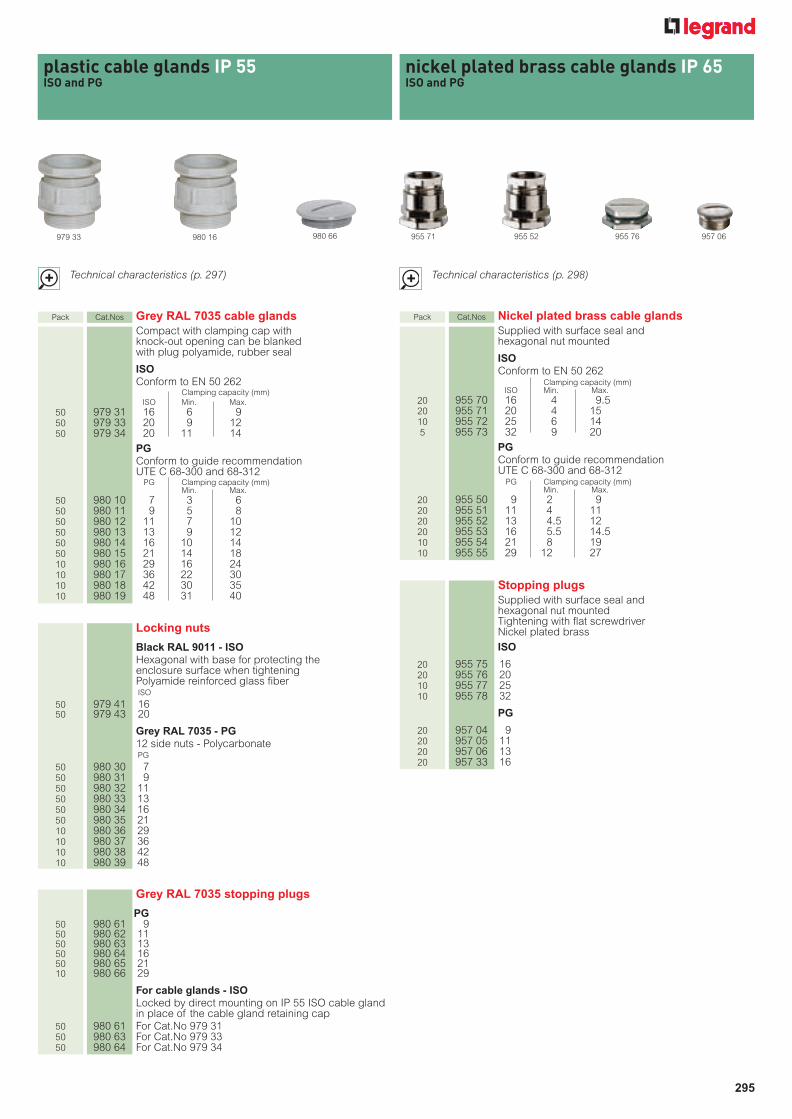
295
Technical characteristics (p. 297)
plastic cable glands IP 55ISO and PG
980 16 980 66
Pack Cat.Nos Grey RAL 7035 cable glandsCompact with clamping cap withknock-out opening can be blankedwith plug polyamide, rubber seal
ISOConform to EN 50 262
Clamping capacity (mm)ISO Min. Max.
50 979 31 16 6 950 979 33 20 9 1250 979 34 20 11 14
PGConform to guide recommendationUTE C 68-300 and 68-312
PG Clamping capacity (mm)Min. Max.
50 980 10 7 3 650 980 11 9 5 850 980 12 11 7 1050 980 13 13 9 1250 980 14 16 10 1450 980 15 21 14 1810 980 16 29 16 2410 980 17 36 22 3010 980 18 42 30 3510 980 19 48 31 40
955 76
nickel plated brass cable glands IP 65ISO and PG
955 52 957 06
Technical characteristics (p. 298)
Locking nuts
Black RAL 9011 - ISOHexagonal with base for protecting the enclosure surface when tighteningPolyamide reinforced glass fiber ISO
50 979 41 1650 979 43 20
Grey RAL 7035 - PG12 side nuts - PolycarbonatePG
50 980 30 750 980 31 950 980 32 1150 980 33 1350 980 34 1650 980 35 2110 980 36 2910 980 37 3610 980 38 4210 980 39 48
Grey RAL 7035 stopping plugs
PG50 980 61 950 980 62 1150 980 63 1350 980 64 1650 980 65 2110 980 66 29
For cable glands - ISOLocked by direct mounting on IP 55 ISO cable gland in place of the cable gland retaining cap
50 980 61 For Cat.No 979 3150 980 63 For Cat.No 979 3350 980 64 For Cat.No 979 34
Pack Cat.Nos Nickel plated brass cable glandsSupplied with surface seal andhexagonal nut mounted
ISOConform to EN 50 262
Clamping capacity (mm)ISO Min. Max.
20 955 70 16 4 9.520 955 71 20 4 1510 955 72 25 6 145 955 73 32 9 20
PGConform to guide recommendationUTE C 68-300 and 68-312
PG Clamping capacity (mm)Min. Max.
20 955 50 9 2 920 955 51 11 4 1120 955 52 13 4.5 1220 955 53 16 5.5 14.510 955 54 21 8 1910 955 55 29 12 27
Stopping plugsSupplied with surface seal andhexagonal nut mountedTightening with flat screwdriverNickel plated brass
ISO
20 955 75 1620 955 76 2010 955 77 2510 955 78 32
PG
20 957 04 920 957 05 1120 957 06 1320 957 33 16
979 33 955 71

296
plastic cable glands IP 68multi-entry plastic cable glands IP 66
Cat.Nos Threading internal Ø for cables (mm)
980 03/23 ISO 20 - PG 13.5 12.5980 05/25/49 ISO 25 - PG 21 18.5980 06/26/50 ISO 32 - PG 29 25.5980 07/27/51 ISO 40 - PG 36 32.5980 09/29 ISO 63 - PG 48 44.5
■ Multi-entry cable plastic glands and seals ■ Grey RAL 7001 cable glands
CharacteristicsHalogen-free polyamide UL 94-V2Operating temperature: - 20 °C to + 80°CSelf-extinguishing 960°C according to IEC 60695-2-11
Dimensions (mm)
3 inputsCat.Nos 980 55/56
4 inputsCat.Nos 980 57/58
7 inputsCat.No 980 60
ASI sealCat.No 980 54
AB
Ø D
C F
C1
to fl
at
Ø D
1
E
A B Ø DC
FDrilling
C1 E ØD1Cat.Nos Threading(to flat) Ø
980 00 ISO 12 22 10 16.8 15 11.9 12.7 19 5 21980 01 ISO 16 26 10 21 19 15.9 16.2 22 5 24980 03 ISO 20 29 12 26.5 24 19.8 20.4 26 6 28980 05/49 ISO 25 35 15 36 33 24.8 25.4 32 6 35980 06/50 ISO 32 40 15 46.5 42 31.6 32.5 42 7 43980 07/51 ISO 40 49 17 58.5 53 39.9 40.5 50 7 56980 08 ISO 50 54 17 66.5 60 50 50.8 60 8 66980 09 ISO 63 54 18 75 68 62.9 64 75 8 82
ISO
PG
A B Ø DC
FDrilling
C1 E ØD1Cat.Nos Threading(to flat) Ø
980 20 PG 7 22 10 16.8 15 12.5 12.7 19 5 21980 21 PG 9 26 10 21 19 15.2 15.2 22 5 24980 22 PG 11 27 12 24.5 22 18.6 18.6 24 5 26980 23 PG 13.5 29 12 26.5 24 20.4 20.4 26 6 28980 24 PG 16 30 13 29.5 27 22.5 22.5 32 6 35980 25 PG 21 35 15 36 33 28.3 28.3 36 7 38980 26 PG 29 40 15 46.5 42 37 37 46 7 51980 27 PG 36 49 17 58.5 53 47 47 60 8 66980 28 PG 42 54 17 66.5 60 54 54 70 8 78980 29 PG 48 54 18 75 68 60 60 75 8 82
■ Grey RAL 7001 stopping plugs
Dimensions (mm)
Cat.NosThreading Ø D D1 F X G B E
ISO980 41 ISO 16 15.8 20.5 8 x 2 12 3.9980 43 ISO 20 19.8 25 8 x 2 12 3.8980 45 ISO 25 24.8 30.5 8 x 2 12 4.4980 46 ISO 32 31.8 38 8 x 2 12 4.9980 47 ISO 40 39.8 46.5 8 x 2 12.5 4.9
Ø D1
FxG
B
E
Ø D

297
plastic cable glands IP 55x
Ø D to edge
C to flats
AB
Body (mm)
Cat.Nos Threading Ø DrillingPG Ø D C A B smooth
to edge to flat hole
980 10 7 16.6 15 11 6.5 12.7980 11 9 21 19 11.5 7 15.2980 12 11 24 22 12 8 18.6980 13 13 26.5 24 13 9 20.4980 14 16 29.75 27 13.5 9 22.5980 15 21 35.25 32 16.5 10 28.3980 16 29 45 41 18.5 12 37980 17 36 60 55 21.5 14 47980 18 42 65.5 60 22 16 54980 19 48 71 65 23 16 60
PG
Body (mm)
Cat.Nos Threading Ø DrillingISO Ø D C A B smooth
to edge to flat hole
979 31 16 21 19 11.5 7 15.2979 33 20 26.5 24 13 9 20.4979 34 20 29.75 27 13.5 9 20.4
ISO
■ RAL 7035 cable glands
Ø D1 B HCat.Nos Threading (mm) (mm) (mm)
980 61 PG 9 19 6.5 –980 62 PG 11 22 6.5 10980 63 PG 13 25.5 6.5 10980 64 PG 16 27 6.5 10980 65 PG 21 34 8 11.5980 66 PG 29 44 8 12
H
Ø D1
B
Dimensions (mm)
■ RAL 7035 stopping plugs
C E Ø D1Cat.Nos Threading to flat (mm) (mm)
980 30 PG 7 15 4.5 17.3980 31 PG 9 19 4.5 21.9980 32 PG 11 22 5 25.4980 33 PG 13 24 5.5 27.7980 34 PG 16 27 6 31.1980 35 PG 21 32 6.5 36.9980 36 PG 29 41 7.5 47.3980 37 PG 36 54 8.5 62.4980 38 PG 42 60 9 69.3980 39 PG 48 67 9.5 77.4
E
CØ D1
Dimensions (mm) RAL 7035
■ Locking nuts
PG
PG
Dimensions (mm) RAL 9011
C1
to fl
at
Ø D
1
E
ISOC1
Cat.Nos Threading to flat E Ø D1
979 41 ISO 16 22 5 24979 43 ISO 20 26 6 28
nickel plated brass cable glands IP 65x
■ CharacteristicsOperating temperature: – 15°C to + 60°CCable gland and plug material : nickel-plated brass CuZn 40 Pb 3 zinc-plated steel grainNatural rubber peelable ring Shore 60 for adapting to exact diameter of cable used
C to flats
I to flats
D1 to edge
BA
max
.
C1 to flats
Height Ø DrillingCat.Nos Threading I C C1 D1 B A smooth
to flat to flat to flat to flat max. holeISO
955 70 16 15 17 20 22.2 7 25 16.5955 71 20 18 20 24 26.7 7 25 20.5955 72 25 22 26 30 33.5 8 29 25.5955 73 32 28 32 35 38.5 8.5 32 32.5
PG955 50 09 15 17 19 21.1 6 17.5 15.2955 51 11 18 20 21 23.5 6 17.5 18.6955 52 13 20 22 23 25.5 6.5 18.5 20.4955 53 16 22 24 26 29 6.5 20.5 22.5955 54 21 28 30 32 35.5 7 23 28.3955 55 29 37 40 41 45 8 25 37
Stopping plugs
C to flats
D1 to edge
B
H
C1 to flats
Cat.Nos Threading C C1 D1 B HISO
955 75 16 17 20 22.2 7 10955 76 20 23 24 26.7 7 10955 77 25 29 30 33.5 8 11.5955 78 32 29 35 38.5 8.5 12.5
PG957 04 09 17 19 21.1 6 9957 05 11 19 21 23.5 6 9957 06 13 21 23 25.5 6.5 9.5957 33 16 23 26 29 6.5 9.5
■ Dimensions (mm)
Dimensions (mm)

298 299
RTA flexible conduits are chosen according to the mechanical, dynamic and environmental stresses
The classification in standard EN 50086-1can be used to define the mechanical and thermal characteristics of a product using 4 digits
RTA flexible conduits
Products and systems[
PRO
TECT
ION
OF
CAB
LES
]
For each application and environmental stress there is a correspondingpolyamide, PVC or metal-plastic flexible conduit solution, ideal for a widerange of sectors
Composition of the systems How to select your conduit
DYNAMICSTRESSES
Classificationacc. to
EN 50086-1
MECHANICALSTRESSES
ENVIRONMENTAL STRESSES Conformity to requirements
of standardsMovement Compression Impact Cold Heat Splashes Weatherproof
POLY
AMID
E
SFP standard
2223(1)
2443
(1) (1) IP66 without sealIP68 with seal
EN 50086-1EN 61386-1
NF R 13-903(2)
SFProbotic
1142(1)
1452
(1) IP66 without sealIP68 with seal
EN 50086-1EN 61386-1
SFP TR 2443 IP66 without sealIP68 with seal
EN 50086-1EN 61386-1
PVC
GE-PVC - IP65(3)
FP 2000 2311 IP44(3)
IP66(4)EN 50086-1EN 61386-1
META
L-PL
ASTI
CFA 3331 IP65(4) EN 50086-1
EN 61386-1
PN 3331 IP65(4) EN 50086-1EN 61386-1
P2 4431 IP65(4)EN 50086-1EN 61386-1
UL 224
Very good resistance Good resistance Limited resistance
(1) Outer diameter <12 mm - (2) Pending - (3) With universale connector - (4) With Metal 2000 connector
PVC conduitsSFP
polyamideconduits
Metal-plastic conduits
PVC SYSTEMParticularly suitable for environmentswhere excellent resistance to externalagents is required: oils, diluted acids, sparks • Provides a high degree of resistance to:
- Mechanical stresses (impact and compression)- Environmental stresses (splashes)
• System consisting of 2 types of conduitwith connectors.
• Suitable, for example, for machining centres, welding shops, etc
METAL-PLASTIC SYSTEMParticularly suitable for environmentswhere strength is required
• Provides a high degree of resistance to:- Mechanical stresses (impact and compression)- Tensile and torsional stresses
• System consisting of 3 types of conduit with connectors
• Suitable, for example, for machines insevere mechanical environments
SFP POLYAMIDE SYSTEM:Particularly suitable for environments where flexibility is required
• Provides a high degree of resistance to:- Dynamic stress (movement)- Mechanical stress (impact)- Environmental stresses (splashes of chemical agents, weatherproofing)- Low temperatures (- 45°C)
• System consisting of 3 types of conduit with connectors and junctions
• Suitable, for example, for mobile equipment, machinery or robotics, etc.
1st digit 2nd digit 3rd digit 4th digitCompressive strength Impact strength Minimum temperature Maximum temperature
1 = 125 N (very low) 1 = 0.5 J (very low) 1 = + 5°C 1 = + 60°C
2 = 320 N (low) 2 = 1 J (low) 2 = - 5°C 2 = + 90°C
3 = 750 N (average) 3 = 2 J (average) 3 = - 15°C 3 = + 150°C
4 = 1250 N (high) 4 = 6 J (high) 4 = - 25°C 4 = + 120°C
5 = 4000 N (very high) 5 = 20 J (very high) 5 = - 45°C 5 = + 150°C
6 = + 250°C
7 = + 400°C
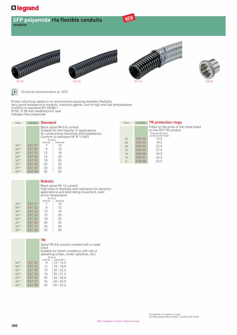
300Red catalogue numbers: New products
SFP polyamide rta flexible conduitsconduits
637 05 637 24
Technical characteristics (p. 302)
Protect electrical cables in an environment requiring excellent flexibilityVery good resistance to impacts, chemical agents, and to high and low temperaturesConform to standard EN 50086-1IP 66, IP 68 with weatherproof sealHalogen-free polyamide
Pack Cat.Nos StandardBlack spiral PA 6.6 conduitSuitable for the majority of applicationsfor constructing machines and installationsConform to standard NF R 13-903
Ø (mm)internal external
50(1) 637 01 7 1050(1) 637 02 8 1250(1) 637 03 12 1650(1) 637 04 15 2050(1) 637 05 19 2525(1) 637 06 25 3225(1) 637 07 33 4025(1) 637 08 42 50
RoboticBlack spiral PA 12 conduitHigh level of flexibility and resistance for dynamicapplications and alternating movement, even at low temperature
Ø (mm)internal external
50(1) 637 21 7 1050(1) 637 22 8 1250(1) 637 23 12 1650(1) 637 24 15 2050(1) 637 25 19 2525(1) 637 26 25 3225(1) 637 27 33 4025(1) 637 28 42 50
TRSpiral PA 6.6 conduit covered with a metalbraidSuitable for harsh conditions with risk ofsplashing (chips, solder splashes, etc)
Ø (mm)internal external(2)
50(1) 637 32 8 12 / 14.550(1) 637 33 12 16 / 18.550(1) 637 34 15 20 / 22.550(1) 637 35 19 25 / 27.525(1) 637 36 25 32 / 34.525(1) 637 37 33 40 / 44.525(1) 637 38 42 50 / 52.5
637 34 638 93
Pack Cat.Nos TR protection ringsFitted on the ends of the metal braid on the SFP TR conduit
External Ø (mm)conduit with braid
25 638 92 14.525 638 93 18.525 638 94 22.510 638 95 27.510 638 96 34.510 638 97 44.55 638 98 52.5
(1) Number of meters in pack(2) Only polyamide conduit / conduit with braid
NEW

301
SFP polyamide rta flexible conduitsconnectors and junctions, accessories
Red catalogue numbers: New products
Pack Cat.Nos Connectors and junctions
Provide excellent tensile strength in staticand dynamic applicationsNo tools needed when used with SFPstandard, robotic and TR polyamideconduitsConduit inserted directly, clamped bysimply pulling the ring, locked with a 1/4turn with closing indication IP 66, IP 68 with weatherproof seal Supplied in a sachetBlack halogen-free PA 6.6
Straight and right-angled male connectorsStraight Right- External Ø (mm) Thread
angled polyamide conduit
25 637 50 637 80 10 ISO 1225 15 637 51 637 81 12 ISO 1615 10 637 52 637 82 16 ISO 1615 10 637 53 637 83 16 ISO 20
10 637 54 637 84 20 ISO 2010 637 55 637 85 20 ISO 25
10 5 637 56 637 86 25 ISO 255 637 57 637 87 32 ISO 325 637 58 40 ISO 401 637 59 50 ISO 50
25 637 60 637 90 10 PG 725 637 61 10 PG 9
25 15 637 63 637 91 12 PG 725 15 637 64 637 92 12 PG 9
25 637 65 12 PG 1115 10 637 67 637 93 16 PG 1115 10 637 68 637 94 16 PG 13.5
10 637 70 637 95 20 PG 13.510 637 71 637 96 20 PG 16
10 5 637 72 637 97 25 PG 1610 5 637 73 637 98 25 PG 21
5 637 74 637 99 32 PG 295 637 75 40 PG 361 637 76 50 PG 421 637 77 50 PG 48
Right-angled base connectorsSupplied with joint surfaceExternal Ø (mm) polyamide conduit:
1 638 08 401 638 09 50
Y junctionsExternal Ø (mm) polyamide conduit(1):
1 638 10 12 / 10 - 101 638 12 16 / 12 - 121 638 14 20 / 12 - 121 638 16 20 / 16 - 161 638 18 25 / 20 - 20
637 55 638 10638 09637 85
Pack Cat.Nos Accessories
IP 68 weatherproof sealsFitted at the ends of the conduit to obtain IP 68 withthe connectors and junctions Supplied in a sachetExternal Ø (mm) polyamide conduit:
50 638 61 1050 638 62 1250 638 63 1650 638 64 2010 638 65 251 638 66 3210 638 67 4010 638 68 50
Snap-fixing basesAccessory for holding SFP standard and roboticpolyamide conduitsFixed with screws (not supplied)Conduit simply clipped in place and closed with a coverBases can be used with clips suppliedSupplied in a sachetBlack PA 6.6External Ø (mm) conduit:
25 638 71 1025 638 72 1225 638 73 1610 638 74 2010 638 75 2510 638 76 325 638 77 405 638 78 50
NutsHexagonal with conduit support in order toprotect the casing surface when tighteningBlack reinforced fibreglass PA 6
50 979 40 ISO 1250 979 41 ISO 1650 979 43 ISO 2050 979 45 ISO 2525 979 46 ISO 3225 979 47 ISO 4025 979 48 ISO 5025 979 49 ISO 63
50 979 50 PG 750 979 51 PG 950 979 52 PG 1150 979 53 PG 13.550 979 54 PG 1650 979 55 PG 2125 979 56 PG 2925 979 57 PG 3625 979 58 PG 4225 979 59 PG 48
638 65 638 74 Example ofassociated bases
979 45
(1) Arrival/departures
NEW

302 303
SFP polyamide rta flexible conduits
ISO
ThreadDimensions (mm)
Cat.NosØ DU A B C Ø D Ø E
637 80 ISO 12 7 16 33.5 10 17.5 24637 81 ISO 16 8.2 17 34 10 21 26637 82 ISO 16 10.4 19.5 39.5 12 26 30.5637 83 ISO 20 10.4 19.5 39.5 12 26 30.5637 84 ISO 20 13.8 22 41.5 14 31 34.5637 85 ISO 25 13.8 22 41.5 14 31 34.5637 86 ISO 25 16.9 25 48 14 34 39.5637 87 ISO 32 25.3 28.5 58.5 14 43 47
PG
ThreadDimensions (mm)
Cat.NosØ DU A B C Ø D Ø E
637 90 PG 7 7 16 33.5 10 17.5 24637 91 PG 7 8.2 17 34 10 21 26637 92 PG 9 8.2 17 34 10 21 26637 93 PG 11 10.4 19.5 39.5 12 26 30.5637 94 PG 13.5 10.4 19.5 39.5 12 26 30.5637 95 PG 13.5 13.8 22 41.5 14 31 34.5637 96 PG 16 13.8 22 41.5 14 31 34.5637 97 PG 16 16.9 25 48 14 34 39.5637 98 PG 21 16.9 25 48 14 34 39.5637 99 PG 29 25.3 28.5 58.5 14 43 47
Dimensions (mm)Cat.Nos
A B C Ø D E F G638 08 130 60 89 47 13 43 75638 09 155 60 89 55 13 43 75
Right-angled male connectors 90°
Right-angled base connectors 90°
Ø E
A
Ø D
U
Ø D
B
C
■ Characteristics
A
Ø D
B
Ø D
U
C
R
■ Dimensions
Straight male connectors
ISO
ThreadDimensions (mm)
Cat.NosØ DU A B C (across flat) Ø D
637 50 ISO 12 7 41.5 10 22 24637 51 ISO 16 9 41.5 10 24 26637 52 ISO 16 11 46 12 28 30.5637 53 ISO 20 12.5 46 12 28 30.5637 54 ISO 20 14.5 49 14 32 34.5637 55 ISO 25 15.5 49 14 32 34.5637 56 ISO 25 19 52 14 38 39.5637 57 ISO 32 26 56 14 45 47637 58 ISO 40 33.4 59 14 54 55637 59 ISO 50 42.8 66 16 64 65
PG
ThreadDimensions (mm)
Cat.NosØ DU A B C (across flat) Ø D
637 60 PG 7 7 41.5 10 22 24637 61 PG 9 7 41.5 10 22 24637 63 PG 7 8 41.5 10 24 26637 64 PG 9 9 41.5 10 24 26637 65 PG 11 9 41.5 10 24 26637 67 PG 11 12.5 46 12 28 30.5637 68 PG 13.5 12.5 46 12 28 30.5637 70 PG 13.5 15.5 49 14 32 34.5637 71 PG 16 15.5 49 14 32 34.5637 72 PG 16 17.5 52 14 38 39.5637 73 PG 21 19 52 14 38 39.5637 74 PG 29 26 56 14 45 47637 75 PG 36 33.4 59 14 54 55637 76 PG 42 42.8 66 16 64 65637 77 PG 48 42.8 66 16 64 65
Cat.NosR min. (mm)(1)
int. Ø (mm)Standard Robotic TR
637 01/21 7 18 16 -637 02/22/32 8 20 18 23637 03/23/33 12 25 22 25637 04/24/34 15 30 27 30637 05/25/35 19.5 40 36 40637 06/26/36 25.5 50 45 55637 07/27/37 33 60 54 70637 08/28/38 42 70 63 110
SFP polyamide conduit Standard Robotics TR
Materials(1) PA 6.6 PA 12 PA 6.6 +zinc-plated steel
ext. diam. �12 mm 2 2 2 3 1 1 4 22 4 4 3
ext. diam. > 12 mm 2 4 4 3 1 4 5 2Compressive strength 320 N 125 N 320 N
ext. diam. �12 mm IK 06 (1 joule) IK 04 (0.5 joule)IK 08 (6 joules)
ext. diam. > 12 mm IK 08 (6 joules) IK 08 (6 joules)min. - 25 °C - 45 °C - 25°Cmax. + 105 °C + 90 °C + 105 °C
Protection acc. to IEC EN 50086-1 IP 66/IP 68 (with seal)Held the U.V. 500 h 500 h > 500 hSelf-extinguishing acc. to EN 50086-1 Flame-retardant
750 °C
••• ••• •••
••• ••• •••
Diesel ••• •• •••••• ••• •••
• • -
••• ••• •••
••• ••• •••
Conduit bending radius
IP 68 weatherproof seal Snap-fixing base
Dimensions (mm)Cat.Nos
A Ø B C Ø D638 01 10 9.7 3.5 5.4638 02 10 11.7 3.5 7.4638 03 11 15.6 3.5 11.4638 04 15 19.8 5 14.1638 05 18 24.9 7 17.6638 06 23 31.9 9 23.4638 07 24.5 39.9 9 31.4638 08 27.5 49.9 10 40.1
Dimensions (mm)Cat.Nos
A B C Ø D638 71 21.5 22.5 18 10638 72 24.5 23.5 18 12638 73 28.5 26 18 16638 74 32.5 32 18 20638 75 39 38 18 25638 76 45 46.5 18 32638 77 53.5 53.5 18 40638 78 61 63 18 50
A
C
Ø B
Ø D
A
B C
Ø D
Cat.NosDimensions (mm)
H L Depth Ø A Ø B C Ø D638 10 70 65 32 26 24 30 5.5638 12 77 70 32 30.5 26 30 5.5638 14 82 72 41 34.5 26 30 6.5638 16 86 81 41 34.5 30.5 42 6.5638 18 92 86 41 39.5 34.5 42 6.5
Y junctions
60°
L
H
ØB
ØA
C
ØD
(1) Halogen-free materials(2) Min. - 45 °C, max. + 105 °C for connectors and junctions(3) 850 °C for connectors and junctions
••• Very good•• Good• Limited
(1) Indicative dimensions
OFF
ON
Ø D G C
E
F
OFF
ON
Ø D
B
ANuts
Cat.NosDimensions (mm)
ThreadC E Ø D
979 40 ISO 12 19 5 21979 41 ISO 16 22 5 24979 43 ISO 20 26 6 28979 45 ISO 25 32 6 35979 46 ISO 32 41 7 43979 47 ISO 40 50 7 56979 48 ISO 50 60 8 66979 49 ISO 63 75 8 82
ISO PGC
Ø D
E
TR protection rings
Cat.NosDimensions (mm)
A Ø B C Ø D
637 32 21 19.7 6 12
637 33 21 24.8 6 16
637 34 21 28.8 6 20
637 35 21 34.6 8 25
637 36 21 42 8 32
637 37 21 50 10 40
637 38 21 61 10 50
C
A
ØB
ØD
Dimensions (mm)Cat.Nos Thread
C E Ø D
979 50 PG 7 19 5 21979 51 PG 9 22 5 24979 52 PG 11 24 5 26979 53 PG 13.5 26 6 28979 54 PG 16 32 6 35979 55 PG 21 36 7 38979 56 PG 29 46 7 51979 57 PG 36 60 8 66979 58 PG 42 70 8 76979 59 PG 48 75 8 81
■ Installation
Assembling the SFP polyamide rta connector
1. Insert the conduit 2. Clamp theconnector bypulling on the ring
Assembling the weatherproof seal
1. Position the seal on theconduit
2. Fit the connector
3. Lock with a 1/4turn
Assembling the TR protection ring
1. Composition of the assembly 2. Place the protection ring inposition
3. Fit the connector
Classification acc.to EN 50086-1
ImpactstrengthOperatingtemperatures(2)
Self-extinguishing(3) acc. toIEC EN 60695-2-11
Resistance to themain chemicalagents
Lead-free petrol
Dilute industrial detergents
Lubricating oils
Dilute acids
Dilute alkalinesolutionsCleaningsolvents

304Red catalogue numbers: New products
PVC and metalloplastic rta flexible conduits
635 05 635 25
635 51635 45 635 62
Technical characteristics (p. 306)
Pack Cat.Nos PVC
GE - PVCSimple conduit in grey smooth PVCIP 65 with Universale connectors
Ø (mm)internal external
50(1) 635 01 10 1450(1) 635 02 12 1650(1) 635 03 15.5 20.550(1) 635 04 20.5 26.525(1) 635 05 27 33.525(1) 635 06 34.5 41.525(1) 635 07 39.5 47.525(1) 635 09 51 61
FP 2000Conduit in grey PVC with reinforcement Smooth interior allows cables to slide through easilyEnsures excellent mechanical resistanceIP 44 with Universale connectors IP 66 with Metal 2000 connectors
Ø (mm)internal external
50(1) 635 21 10 15.550(1) 635 22 12.5 17.550(1) 635 23 16 2150(1) 635 24 21 2625(1) 635 25 27 33.525(1) 635 26 35.5 42.525(1) 635 27 40.5 48.525(1) 635 29 52 60.5
Pack Cat.Nos Metalloplastic
Excellent mechanical resistanceElectrical continuity guaranteed with Metal 2000connectorsIP 65 with Metal 2000 connectors
FASingle seam connection steel conduit,coated with aspirated grey PVC
Ø (mm)internal external
50(1) 635 41 10 1450(1) 635 42 12 15.550(1) 635 43 15.5 19.550(1) 635 44 20.5 24.525(1) 635 45 26.5 31.525(1) 635 46 34.5 4025(1) 635 47 39.5 4525(1) 635 49 50.5 56
PNSingle seam connection steel conduit,coated with smooth grey PVCExcellent resistance to wear and abrasion
Ø (mm)internal external
50(1) 635 51 10 15.550(1) 635 52 12 1850(1) 635 53 15.5 21.550(1) 635 54 20.5 2725(1) 635 55 26.5 3425(1) 635 56 34.5 42.525(1) 635 57 39.5 48.525(1) 635 59 50.5 61
P2Double seam connection steel conduit,coated with grey smooth PVCEnhanced mechanical resistance to tensile andtorsional stress
Ø (mm)internal external
50(1) 635 61 10 15.550(1) 635 62 12 1850(1) 635 63 15.5 21.550(1) 635 64 20.5 2725(1) 635 65 26.5 33.525(1) 635 66 34.5 42.525(1) 635 67 39.5 4825(1) 635 69 50.5 60
Protect electrical cables in a harsh environment requiring good resistance to oils and dilute acidsExcellent flexibilityFP 2000 PVC and metalloplastic conduits conforming to standard EN 50086-1P2 metalloplastic conduits conforming to standard UL 224
(1) Number of meters in pack
NEW

305Red catalogue numbers: New products
PVC and metalloplastic rta flexible conduits connectors
636 06 636 38 636 76 979 88
Pack Cat.Nos Connectors for PVC conduits
Universale straight male connectorsIP 65 with GE-PVC conduitIP 44 with FP 2000 conduitSupplied in a sachetGrey reinforced fibreglass PA 6
Ø conduit (mm) Threadmin. internal max. external
25 636 01 10 16 ISO 1625 636 02 12 18 ISO 1625 636 03 12 18 ISO 2010 636 04 15 21.5 ISO 2010 636 05 20 26.5 ISO 255 636 06 27 33.5 ISO 321 636 09 34.5 42.5 ISO 401 636 10 39 50 ISO 401 636 12 50 61 ISO 5025 636 21 10 16 PG 925 636 22 12 18 PG 1125 636 23 12 18 PG 13.510 636 24 15 21.5 PG 13.510 636 25 15 21.5 PG 1610 636 26 20 26.5 PG 215 636 27 27 33.5 PG 29
Nuts for Universale connectorsHexagonal with conduit support in order toprotect the casing surface when tighteningBlack reinforced fibreglass PA 6
50 979 41 ISO 1650 979 43 ISO 2050 979 45 ISO 2525 979 46 ISO 3225 979 47 ISO 4025 979 48 ISO 5025 979 49 ISO 6350 979 51 PG 950 979 52 PG 1150 979 53 PG 13.550 979 54 PG 1650 979 55 PG 2125 979 56 PG 29
Pack Cat.Nos Connectors for FP 2000 PVCand metalloplastic conduits
Metal 2000 male connectorsSealing ring providing the IP between the connector and the conduitIP 66 with PVC FP 2000 conduit IP 65 with metalloplastic conduits Tinned steel ferrule screwed inside the metalconduit to ensure electrical continuity andprotection of cables Supplied in a sachet. Nickel-plated brass
Straight Right- Internal Ø Threadangled (mm) conduit
1 636 31 636 71 10 ISO 161 636 32 636 72 12 ISO 161 636 33 636 73 12 ISO 201 636 35 636 74 15.5 ISO 201 636 37 636 75 20.5 ISO 251 636 38 26.5 ISO 251 636 39 636 76 26.5 ISO 321 636 40 636 77 34.5 ISO 401 636 41 636 78 39.5 ISO 501 636 42 636 79 50.5 ISO 631 636 52 636 82 10 PG 91 636 53 636 83 10 PG 111 636 55 636 84 12 PG 111 636 58 636 86 15.5 PG 13.51 636 59 636 87 15.5 PG 161 636 60 636 88 20.5 PG 211 636 61 636 89 26.5 PG 291 636 62 636 90 34.5 PG 361 636 63 636 91 39.5 PG 421 636 64 636 92 50.5 PG 48
Nuts for Metal 2000 connectorsNickel-plated brass
50 979 81 ISO 1650 979 83 ISO 2050 979 85 ISO 2550 979 86 ISO 3225 979 87 ISO 4010 979 88 ISO 5010 979 89 ISO 6350 979 91 PG 950 979 92 PG 1150 979 93 PG 13.550 979 94 PG 1650 979 95 PG 2125 979 96 PG 2925 979 97 PG 3610 979 98 PG 4210 979 99 PG 48
NEW

306
PVC rta flexible conduits and Universale connectors
■ Characteristics
Ø D
U
A
BC
R
■ Dimensions
Universale straight male connectors
ISO
ThreadDimensions (mm)
Cat.NosØ DU A B (across flat) C (across flat)
636 01 ISO 16 8 10 24 25636 02 ISO 16 10 12 26 28636 03 ISO 20 10 12 26 28636 04 ISO 20 13 13 31 34636 05 ISO 25 18 14 36 40636 06 ISO 32 24 15 45 48636 09 ISO 40 32 15 54 60636 10 ISO 40 34 15 61 67636 12 ISO 50 45.5 20 73 80
PG
ThreadDimensions (mm)
Cat.NosØ DU A B (across flat) C (across flat)
636 21 PG 9 8 10 24 25636 22 PG 11 10 12 26 28636 23 PG 13.5 10 13 26 28636 24 PG 13.5 13 13 31 34636 25 PG 16 13 13 31 34636 26 PG 21 18 14 36 40636 27 PG 29 24 15 45 48
GE-PVC FP 2000Cat.Nos Ø internal R min. (mm)(1) Cat.Nos Ø internal R min. (mm)(1)
635 01 10 25 635 21 10 40635 02 12 30 635 22 12.5 55635 03 15.5 40 635 23 16 70635 04 20.5 50 635 24 21 80635 05 27 70 635 25 27 90635 06 34.5 80 635 26 35.5 120635 07 39.5 90 635 27 40.5 140635 09 51 110 635 29 52 160
PVC conduit GE - PVC FP 2000Materials plasticized PVC PVCClassification according to EN 50086-1 - 2 3 1 1Compressive strength - 320 NImpact strength - IK 07 (2 joules)
min. - 15 °C + 5 °Cmax. + 70 °C + 60 °C
IP 65 IP 44
- IP 66
Fire resistance(2) in accordancewith EN 50086-1
Flameproof
•• •••
••• •••
Diesel •• •••
••• ••
•• ••
• •
•• •
(1) Min. - 20 °C, max. 80 °C for connectors(2) Universale connectors, self-extinguishing at 850 °Cacc. to IEC EN 60695-2-11 - V.O. acc. to UL 94
(1) Indicative dimensions
••• Very good•• Good• Limited
Conduit bending radius
Nuts for Universale connectors
DimensionsCat.Nos Thread
C E Ø D
979 41 ISO 16 22 5 24
979 43 ISO 20 26 6 28
979 45 ISO 25 32 6 35
979 46 ISO 32 41 7 43
979 47 ISO 40 50 7 56
979 48 ISO 50 60 8 66
979 49 ISO 63 75 8 82
ISO
PG
C
Ø D
E
DimensionsCat.Nos Thread
C E Ø D
979 51 PG 9 22 5 24979 52 PG 11 24 5 26979 53 PG 13.5 26 6 28979 54 PG 16 32 6 35979 55 PG 21 36 7 38979 56 PG 29 46 7 51
■ Installation
Assembling the Universale connector
1. Composition of the assembly 2. Clamp ring run along andconduit inserted
3. Assembled elements aftertightening
Operatingtemperatures(1)
Protection inaccordance withIEC EN 60529
With Universaleconnector
With Metal 2000connector
Lead-freepetrol
Dilute industrialdetergents
Lubricatingoils
Resistance to themain chemicalagents
Dilute acids
Dilute alkalinesolutions
Cleaningsolvents

307
metalloplastic rta flexible conduits and Metal 2000 connectors
Ø C
D
Ø DU
A
B
Metal 2000 right-angled male connectors 90°
CE
Nuts for Metal 2000 connectors
ISO
Cat.Nos ThreadDimensions (mm)
C E979 81 ISO 16 19 3979 83 ISO 20 24 3.5979 85 ISO 25 30 4979 86 ISO 32 36 4979 87 ISO 40 46 5979 88 ISO 50 60 5979 89 ISO 63 70 5
PG
Cat.Nos ThreadDimensions (mm)
C E979 91 PG 9 18 2.8979 92 PG 11 21 3979 93 PG 13.5 23 3979 94 PG 16 26 3979 95 PG 21 32 3.5979 96 PG 29 41 4979 97 PG 36 51 5979 98 PG 42 60 5979 99 PG 48 64 5.5
■ Characteristics
R
■ Dimensions
Metal 2000 straight male connectors
FA PN P2
Cat.Nos Ø internal R min. Cat.Nos Ø internal R min. Cat.Nos Ø internal R min.(mm)(1) (mm)(1) (mm)(1)
635 41 10 30 635 51 10 35 635 61 10 50635 42 12 35 635 52 12 50 635 62 12 65635 43 15.5 40 635 53 15.5 70 635 63 15.5 80635 44 20.5 60 635 54 20.5 80 635 64 20.5 110635 45 26.5 100 635 55 26.5 110 635 65 26.5 130635 46 34.5 110 635 56 34.5 135 635 66 34.5 150635 47 39.5 150 635 57 39.5 160 635 67 39.5 190635 49 50.5 200 635 59 50.5 200 635 69 50.5 230
Conduit bending radius
Metalloplastic conduit FA PN P2Materials PVC coated hot dip galvanized steelClassification according to EN 50086-1 3 3 3 1 3 3 3 1 4 4 3 1Compressive strength 750 N 750 N 1250 N
IK 07 (2 joules) IK 07 (2 joules) IK 08 (6 joules)min. - 15 °Cmax. + 60 °C
IP 65
Self-extinguishing in accordancewith EN 50086-1
Flameproof
••• •• •••
••• ••• •••
Diesel •• •• ••
••• ••• •••
•• • •
• • •
• • •
B
Ø D
U
C
A
••• Very good•• Good• Limited
(1) Min. -20 °C, max. 80 °C for connectors
(1) Indicative dimensions
ISO
ThreadDimensions (mm)
Cat.NosØ DU A B (across flat) C (across flat)
636 31 ISO 16 8.5 10 20 22636 32 ISO 16 10 10 24 26636 33 ISO 20 10 10 24 26636 35 ISO 20 14 10 27 29636 37 ISO 25 19 10 33 35636 38 ISO 25 24 10 43 35636 39 ISO 32 24 12 43 45636 40 ISO 40 32 14 51 54636 41 ISO 50 37 14 60 62636 42 ISO 63 47 16 74 77
PG
ThreadDimensions (mm)
Cat.NosØ DU A B (across flat) C (across flat)
636 52 PG 9 8.5 10 20 22636 53 PG 11 8.5 10 20 22636 55 PG 11 10 10 24 26636 58 PG 13.5 14 10 27 29636 59 PG 16 14 10 27 29636 60 PG 21 19 10 33 35636 61 PG 29 24 12 43 45636 62 PG 36 32 14 51 54636 63 PG 42 37 14 60 62636 64 PG 48 47 16 74 77
ISO
ThreadDimensions (mm)
Cat.NosØ DU A B Ø C D (across flat)
636 71 ISO 16 8.5 20.5 10 22 22636 72 ISO 16 10 23 10 25 26636 73 ISO 20 10 23 10 25 26636 74 ISO 20 14 23.5 10 27 29636 75 ISO 25 19 27.5 10 32 35636 76 ISO 32 24 33 14 42 45636 77 ISO 40 32 39 16 51 54636 78 ISO 50 37 47 18 60 62636 79 ISO 63 47 55 20 74 77
PG
ThreadDimensions (mm)
Cat.NosØ DU A B Ø C D (across flat)
636 82 PG 9 8.5 20.5 10 22 22636 83 PG 11 8.5 20.5 10 22 22636 84 PG 11 10 23 10 25 26636 86 PG 13.5 14 23.5 10 27 29636 87 PG 16 14 23.5 10 27 29636 88 PG 21 19 27.5 10 33 35636 89 PG 29 24 33 14 42 45636 90 PG 36 32 39 16 51 54636 91 PG 42 37 47 18 60 62636 92 PG 48 47 55 20 74 77
1. Composition of the assembly 2. Clamp and sealing rings runalong then ferrule screwedinside the metal conduit
3. Assembled elements aftertightening
■ Installation
Assembling the Metal 2000 connector
Impact strength
Operatingtemperatures(1)
Protection in accordance withIEC EN 60529 with metal connector
Lead-freepetrol
Dilute industrialdetergents
Lubricatingoils
Resistance to themain chemicalagents
Dilute acids
Dilute alkalinesolutions
Cleaningsolvents

World Headquarters andInternational Department87045 LIMOGES CEDEX FRANCE☎ : 33 5 55 06 87 87Fax : 33 5 55 06 74 55