Embed Size (px)
Citation preview

Multi-Disciplinary Senior Design ConferenceKate Gleason College of Engineering
Rochester Institute of TechnologyRochester, New York 14623
Project Number: 11565
ITT MIRROR STEERING SYSTEM
Andrew Bishop Electrical Engineer
Matthew Manelis Mechanical Engineer
Ben Geiger Electrical Engineer
Nurkanat Suttibayev Industrial Engineer
Katherine Hall Mechanical Engineer
ABSTRACT
The primary goal of the project is to deliver a device that redirects laser beams with high precision, accuracy, and speed using a mirror. The customer, ITT Geospatial Systems, will use the product on satellites and other aircrafts for pointing lasers or tracking targets.
The mirrors used in the system are interchangeable. However, a 3-inch round mirror is to be used primarily in the final assembly by ITT. This waffle mirror is specifically designed to be extremely light in weight and stable in structure, and is provided by the customer. This mirror rests in an elevated horizontal position by an aluminum dowel rod with a flexure portion that allows for slight movement of the mirror without material failure. Movement of the mirror is achieved by placing four current driven force actuators underneath the mirror. There are two axes of motion with a range of 5 degrees on each axis. Capacitive position sensors are each axis for proper feedback.
Through proper design, assembly and testing, this lightweight mirror pointing assembly will meet as many of the required performance specifications as possible.
NOMENCLATURE
FEA Finite Element AnalysisFOS Factor of SafetyFSM Fast Steering MirrorLIDAR Light Detection and RangingPID Proportional Integral DerivativePCB Printed Circuit BoardRIT Rochester Institute of TechnologyVdc Direct current voltage
INTRODUCTION
The prototype proposed is a beam steering device using a rapidly slewed mirror. At this time, a number of similar optical systems are currently available on the market by suppliers such as Optics in Motion and Newport. The FSMs are primarily much smaller in size (one inch mirror on average), are not designed to perform in a vacuum. They are also associated with an exorbitant cost vary on technical specifications. In fact, a system that closely matches this project’s target specifications is offered for $15,000. [1] The main intention of this project is to build a system that can compete with or outperform similar systems on the market while maintaining a budget of $2,000. The final model will have optimal functioning capacity and will meet preferably all of the high performance parameters specified by ITT.
Aerospace applications include optical sensing of scattered light wherein a variety of parameters of interest can be measured from very far distances with
Copyright © 2011 Rochester Institute of Technology
Proceedings of the Multi-Disciplinary Senior Design Conference Page 2
this technology such as temperature, pressure, position, or vibration. Rapid motion of the mirror is required in order to collect the massive amount of data usually needed. Accuracy, precision, and efficient interaction are the most essential attributes of the system to optimize. This specification is monitored through the move time, the settling time and the slew rate (velocity) of the mirror once it is moved to a particular position at a specified angle of tilt. Furthermore, minimal overshoot and oscillation once the desired position has been attained is essential for accuracy. Seeing as fast time, quick speed, and accuracy are so critical, ITT did advise that their slew rate and settling time specifications were high goal to reach intentionally.
Once our product is supplied to ITT with our design specifications, ITT will alter the system adding their proprietary features for its confidential application. The product for our purposes is therefore supplied ±24V via a common power supply since it will first be used in laboratory applications by ITT. The system will be used to gather information at very long distances and, consequently, a small tilt range of movement of the mirror is sufficient, broad coverage. The entire system including the PCBs, the actuators, sensors and mirror should be safely contained in a cylindrical ~ 3-inch diameter enclosure for protection. All of the specifications fully detailed in Table 1 are important parameters to consider and aim to reach when developing the beam steering device.
Table 1: Performance Specifications
In space applications, it is not really practical to have a system that requires an excess amount of power to run the unit. An aircraft or satellite, for example, will have limited power from the engine or power source that is available for our unit to consume, hence the power consumption limitations. High voltage across the actuators has the potential of inducing high energy arcs in a vacuum, which would be very hazardous. There is also the issue of heat generated from the unit that should be monitored.
Various risks were considered when developing the architecture. Electrical noise would dilute input and feedback signals. This significantly reduces accuracy and is an anticipated very high risk. The signal to noise ratio should be monitored and minimized, as this is one way to measure hysteresis, creep, and sensitivity over life. Staying within the linear range of the voice coil would reduce this greatly as well as feedback and reduced friction.
The components that we have with our system are the mirror, the actuator, and the sensor.
Round shaped mirrors are common for FSM systems because of its evenly distributed mass and mass center location. The flexure type often depends on the application and manufacturer preferences. Furthermore, systems might have additional mirror damping features integrated for precision and accuracy purposes.
Actuators are used to change electrical energy into mechanical energy. There are various types that could be used, but the common application is to provide movement to the mirror with a given controlled amount of electrical input.
Voice coil and piezoelectric actuators are the most practical devices considered as options to use to move the position of the mirror. Voice coil actuators use wire or coil, a permanent magnet, and electric current for propulsion, whereas piezoelectric actuation is based on piezoelectric material that transforms its shape in linear or rotary directions when an electric field is applied. Piezoelectric devices, however, are problematic when supplied high voltage in a vacuum environment, and voice coils have linear behavior. Conclusively, it is extremely crucial that the prototype/device is fast, accurate and precise and therefore the voice coil design would be the best actuator device for its attributes.
The sensors are an essential component of the system; they provide the feedback of the system to the input. It is important to first note that the system is driven by constantly monitoring the position of the mirror. The desired angle of each axis as a function of time in essence is an input providing the position of the mirror mount, which is the vertical distance the actuator moves.
Options of sensors include four main types: memsgyroscope, inductive, capacitive, and optical sensors. The memsgyroscope is not accurate when measuring position, as the integrated signal does not come out clear. Implementation of the inductive is difficult to define, and optical sensors are expensive.
Project P11565

Proceedings of the Multi-Disciplinary Senior Design Conference Page 3
Capacitive sensors are used since they are all desired qualities: accurate, very feasible, and reasonably priced. Capacitive sensors work by monitoring the position of the mirror through the voltage difference between two small conductive plates.The electrical components include the power supply as well as two actuators and two sensors per axis. The circuit boards include the drive PCB which serves both axes, the PID controller PCB, sensor PCB, and power regulators per axis.
The most important considerations in the mechanical realm are the spring constant of the flexure on the dowel rod holding up the mirror as well as protection or containment of the mirror and all components.
DESIGN PROCESS
To clearly define the problem, it was important to first identify the customer needs and specifications. After meeting with Michael O’Brien, our representative member from ITT, a list of required performance specifications were established, as seen in Table 1.
From the customer interview, it was determined that rapid movement with minimal overshoot and high precision and accuracy to each position is essential. More specifically, the quantitative goal is to obtain a slew rate greater than 50 degrees/sec, a settling time of better than 90% in 80 milliseconds, and total power dissipation of less than 5 watts per axis. The system includes optical sensors to provide feedback, and four specifically fabricated actuators to reach all of the desired parameters. These actuators are to be voice coil driven, not piezoelectric, as requested by the customer.
All components of the system will be contained in a 3-inch diameter cylinder, including the actuators that will provide the mechanical force to move the mirror position. Each axis contains two actuators and two sensors in series attached to the drive PCB and sensor PCB.
Once these parameters were established, a house of quality was created in order to determine which specifications were most important to consider during the design process. A number of concepts were then generated, and a concept selection matrix was used to determine which design best met the performance specifications. The final upper half design is shown in Fig. 1, which includes the mirror, mirror mount, flexure spring, and actuators.
Figure 1: Upper Half Assembly
Each system component was carefully designed in order to be integrated into the system. Various computer models were created to simulate each part’s functionality and performance. This was especially crucial, as many components of the system rely on its adjacent counterpart.
The most important components of our assembly are the actuators, as this is what drives the system. Therefore, the design process began with this piece.
Two different types of voice coils were considered for our project. An under hung voice coil is designed so that the coil is larger than the field area in order to preserve linearity. The other type is an over hung voice coil, which has a limited range of motion, but produces more force per unit of current. Because the total vertical motion of the voice coil is only about 1 mm, it was decided that an under hung voice coil would be the best choice, as it would help keep power consumption to a minimum.
The final design of each actuator is a current controlled force device. It consists of an iron outer shell to generate the magnetic field into the right space, a magnet to produce the magnetic field, and a coil of wire to produce an opposing magnetic field which in turn produces a vertical force.
A neodymium magnet and iron core are stacked on top of each other and placed in a larger iron core bored cylinder. In this space, coils of wire are wrapped around the neodymium magnet. As current is induced through the wire, a magnetic field is produced due to the strength and proximity of the magnets. A rigid object is attached between the coils and the mirror mount to transfer this vertical force. The position of the mirror can consequently be manipulated by altering the current through the wire.
Copyright © 2011 Rochester Institute of Technology

Proceedings of the Multi-Disciplinary Senior Design Conference Page 4
The voice coil actuators were modeled using COMSOL Multiphysics, a computer program that has the ability to model magnetic fields. Specific dimensions, such as wall thickness, magnet diameter, and overall height, were altered in order to create the greatest magnetic field possible. The final design has 300 windings and a coil radius of 6.5 mm. The selected design and its resulting magnetic field can be seen in Fig. 2.
Figure 2: Voice Coil Magnetic Strength
From COMSOL, it was determined that a 0.38 Tesla field exists when a 100 mA current is induced. Using Eq. (1), where I is the current induced, B is the magnetic field, N is the number of windings, and Rc is the voice coil radius, a vertical force of 0.466 N is calculated. With this information, all remaining system components could be finalized.
F=2 πI|B|NR c (1)
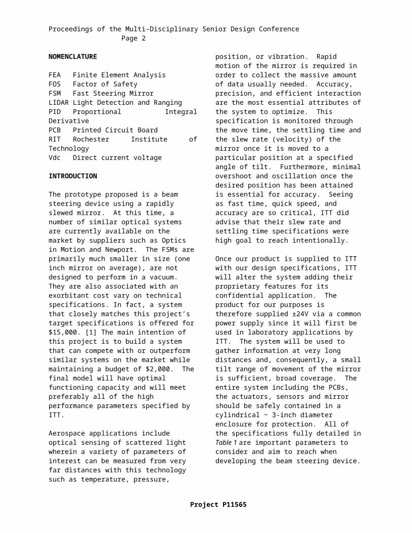
Once the force output was determined, the flexure spring could be designed to translate this force into an angular deflection. A simple flexure design was drawn in SolidWorks, and with FEA software, the spring rate was calculated using SolidWorks Simulation. Various forces were applied to the flexure spring, and the resulting displacements were documented. An Excel graph was generated, plotting the displacements on the x-axis, and the corresponding forces on the y-axis. A trend line was added to the plot, and using Hooke’s Law, the spring rate is equal to the slope of this line. As seen in Fig. 3, the spring rate was calculated to equal 626.8 N/m.
Figure 3 – Force vs. Displacement Plot of Flexure Spring
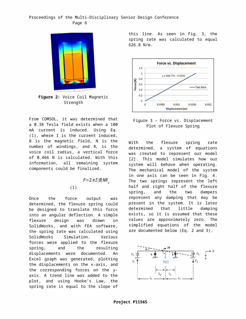
With the flexure spring rate determined, a system of equations was created to represent our model [2]. This model simulates how our system will behave when operating. The mechanical model of the system in one axis can be seen in Fig. 4. The two springs represent the left half and right half of the flexure spring, and the two dampers represent any damping that may be present in the system. It is later determined that little damping exists, so it is assumed that these values are approximately zero. The simplified equations of the model are documented below (Eq. 2 and 3).
Figure 4 – Mechanical model of system
mẍ + 2kx = 2F1 (2)
J Ӫ + 2kL22ө = 2F1L1 (3)
The next components designed for our system are the sensors. Different options were available when designing these parts, such as capacitive, inductive, and a MEMs accelerometer.
Ultimately, a capacitive design was selected. The idea behind this design is to have two plates on the same axis per voice coil. The plates, which are approximately 5x7 mm in size, are conductive pieces through which a change in voltage is measured when movement occurs. While one plate is stationary, the
Project P11565

Proceedings of the Multi-Disciplinary Senior Design Conference Page 5
other moves with respect to the mirror. Once the desired position is reached, the sensor will be able to detect this correct position based on the change in voltage between the two plates.
The mirror mount was originally designed as a square piece, but after careful consideration, the shape was altered to a circular shape. The reason for this change is because dynamically, its best to move the circular mirror with a circular piece, and it reduced the moment of inertia about the pivot point.
The assembly also includes two circular plates. The bottom base plate supports the PCBs, while the upper plate holds the actuators and flexure. These plates are also used for attaching the outer cylinder to the system, as each plate has four holes drilled into the side.
Once all components were finalized, a SolidWorks model was created for each part. An assembly was generated, and the system was simulated in SolidWorks Simulation to ensure that the desired deflection was achieved, while still making sure that no parts would plastically deform under loading. For the worst case scenario, all four actuators are activated, with two pushing up on the mirror, and the other two pulling down. The bottom plate is also constrained, as this piece is not expected to move. This case demonstrates the maximum deflection and stresses that exist within the system. The results of the analysis can be seen in Figs. 5 and 6.
Figure 5 – Vertical Displacement of System
Figure 6 – von Mises Stress of System
From the results shown in Figs. 5 and 6, it is determined that all mechanical components work as expected, with the maximum vertical deflection being 0.065”. Knowing that the radius of the mirror is 3”, a simple trigonometry calculation is performed to yield a tilt degree of 2.5˚. This model represents half of the range that can be achieved, as the mirror could tilt 2.5˚ downward, producing the desired 5˚ of range. The maximum stress within the system is 5.75 ksi, which produces a FOS of about 7. Therefore, no components will plastically deform.
Electronics:Three control electronic circuits are needed to move the system as well as a power regulator circuit to supply constant voltage. The control electonics consist of a controller, a voicecoil driver, and a position sensor for feedback. The controller was imagined as a PID, PI, or PD controller durring the design phase. After determining the equation for motion in one axis, a model was built in simulink.
Figure 7 – Simulink Model for Total System
Initially, an incorrect equation was used which caused a delay in the design by about 2 weeks. As a result, the PCB for the electronics was only partially completed. Even now, there are issues with the equation only dealing with idealities. However, even with the non-idealities not included in the simulink model, the tuning of it can be used as a starting point durring testing and assembly. The controller was tuned and it was then determined that a PD controller
Copyright © 2011 Rochester Institute of Technology
Proceedings of the Multi-Disciplinary Senior Design Conference Page 6
with a pre-amp was needed to attenuate the initial controls by a factor of 10 thousand. This attenuation is very high because the derivative portion of the controls is very small. In order to use real capacitance and resistance values, the preamp had to compensate for the derivative portion. With a preamp gain of .0001 V/V, the PD was tuned to a proportional gain of 845 V/V and a derivative gain of 10,000 V/V. The post-amp was determined to have a gain of 2.5 V/V from this simulation. The pre- and post-amps also act as buffer stages between the input and feedback signals to the PD controller and from the controller to the driver.
Figure 8 – PD Controller Circuit
The driver consists of a voltage controlled current source in the form of a current sourcing opamp with an input buffer and feedback buffer. The voltage gain of this circuit was determined to be approximately 1 V/V (ie, no gain) in PSpice. The load used in simulation in place of voicecoils was a 100 Ω resistor. The 25 ohm resistor is in place to set the current flowing to the voice coil. This produced a current of 100mA through the load, which was the targed goal for the voice coil current.
Figure 9 – Voice Coil Driver Circuit
The power regulator circuit was designed using the LM337T and LM317T power regulator chips. Three cirucits are fed an input of -24V to LM337T and +24V to two LM317Ts. The resistors are used to set the output power at ±15V and +5V. The capacitors are used to reduce the noise of the power regulators at differing frequencies. The +5V is fed back to the outputs of the elctrical system as well as the sensor. The ±15V is fed to the other circuits as voltage rails. The diodes are added as protection diodes for the system.
Figure 10 – Power Regulation Circuit for 5V, +15V, and -15V
The position sensor is a 33kHz oscillator with a capacitor bridge, that measures differentially the voltage across the capacitors in the middle, then multiplies that with the origional signal, and with no phase shift in the capacitor bridge this produces a good phase shift of the signal to ground and up to 66 kHz, which is then amplified and low pass filtered to get rid of the higher frequerncy of the final signal. This circuit required a 5 volt source for the oscillator and the insturmentation amp. The insturmentation amp (AD 623) was chosen for its high commonmode
Project P11565

Proceedings of the Multi-Disciplinary Senior Design Conference Page 7
rejection of around 100dB, as well as its high input impedance so it wouldn’t effect the wave across the capacitve bridge. Then ±15V was required for all the op amps used in filtering, and converting of the square wave of the oscillator to close to a sin wave. The 15V rails are also required for the AD734 multiplier.
Figure 11 – Basic Schematic for Capacitive Sensor (single axis)
With the FEA analyses complete, the next phase of the project is to test each individual component, as well as the system as a whole, to ensure that as many performance specifications are met.
TESTING
In order to make sure our system meets the required specifications, numerous tests are performed. Such tests include the flexure spring constant, power regulator, voice coil driver circuit, proportional derivative circuit, position sensor and open loop voice coil mount, mirror reflectivity, voice coil performance, sensor accuracy, and the overall system testing.
To test the spring rate of the flexure, a test setup was constructed that attached to the flexure. The setup consists of a base piece that the flexure rests on, a top rectangular piece that sits on top of the flexure, and a displacement gage that detects the vertical distance that the flexure travels when a known force is applied. A series of forces are applied to the top rectangular plate, and the corresponding displacement is determined. Much like the FEA modeling, Hooke’s Law is used to determine the spring rate. A plot of force vs. displacement is generated, and the slope of the line passing through each data point is equal to the spring rate.
When testing the mirror reflectivity, a simple setup was constructed. A laser beam is pointed at the mirror, and the resulting image is portrayed a far distance away. If the image portrayed looks similar to the laser beam image portrayed at the same location by itself, then the selected mirror can be used for the assembly. The same technique was used for reflective mirror testing used in overall system testing fixture.
Voice coil functionality testing activities included measuring resistance of the core in the voice coil. The voice coils were considered operational if the
resistance value of the core was 52 Ω ±1. Furthermore, 10V voltage was applied for each voice coil to determine the direction of movement.
Position sensor circuit testing was performed using oscilloscope, power supply and 2 capacitors analogous to the one in actual FSM system. The idea behind the test was to see if swapping the capacitors within the bridge circuit would result in a value proportional to the change in capacitance values that we would expect in the system.
The power regulators were tested on a bread board using 5% resistors. The resistances and capacitances chosen were as close to the designed values as possible (may change this statement). The inputs used were from a DC power supply, with a current limit of .3A. The outputs of the three circuits were +14.6V, +5.3V, and -14.9V. These are acceptable values for a PCB with 5% resistors.
The driver was built on a bread board using 5% resistors and used the voltage rails created by the power regulator. The resistances chosen were, again, as close as possible to the initial design. The voice coils were represented by a 100 Ω resistor. The 25 Ω resistor is rated for 3 watts. The circuit was built and tested. The current through the resistor was 100mA. The gain on the input buffer was changed slightly to accommodate a voltage gain of 1V/V.
The driver was retested with the PD controller connected to the input and with a 10 Vdc input to the PD, a 100 Ω load, and voltages supplied from the Power regulators. The current supplied was approximately 110mA. The gain of the overall electronics was 1.08V/V there was no phase difference from input to output at low frequencies. At 1 kHz sin wave input with a 20 Vpp amplitude, the phase difference was 200 microseconds.
A mirror was mounted at 45º in order to bounce a laser directly onto center of our system and back to a wall located 20 feet behind the laser. DC values and sine waves offset by 90º were used to obtain the data for frequency response and deflection of the system.
RESULTS AND DISCUSSION
Based on tests of individual components, most of the parts are working. Test result showed that PD driver, sensor circuit, voice coils, mechanical mount system, and power regulator are all working. However, the system gets only half a degree deflection while it was designed for two degrees. Settling time specification is satisfied by the system performance, but the
Copyright © 2011 Rochester Institute of Technology

Proceedings of the Multi-Disciplinary Senior Design Conference Page 8
movement time is not. The power consumption specification was not met, which could be improved by more power efficient components.
Figure 12 – DC values for mirror deflection
CONCLUSIONS AND RECOMMENDATIONS
Our findings are that system’s deflection specification was not met due to the voice coils not producing the force they were designed for. Individual components worked well, but they were noisy. This noise could be reduced by integrating PCBs into the system.
For the system as a whole, making the distance from the top of the voice coil’s metal part to the mount where the voice coil cores attach should be shortened. Another recommendation is to look into an inductive position sensor. Another idea is to redesign the voice coils for easier, and more accurate construction, as well as make more pieces then you need to get better matching. The suggestion for the PD controller is, once the position sensor is added, tune on the breadboard to get an idea of where to start, and then retune on the PCB. Furthermore, testing other chips for better frequency response is suggested.
For additional recommendations look up individual’s notes on the project
ACKNOWLEDGMENTS
The team would like to express special thanks to our customer and sponsor, ITT Geospatial Systems, and their representative, Mike O’Brien. We would also like to thank our faculty guide, Alan Raisanen, who significantly helped our team throughout the project. Others to thank include the Mechanical Engineering machine shop members, Mechanical Engineering professors, and Electrical Engineering professors.
REFERENCES
[1]. Optics In Motion, Standard fast Steering Mirrors. Optics in Motion, LLC, n.d. Web. 18 Feb. 2011. <http://www.opticsinmotion.net/ fast_steering_mirrors.html>.[2]. Inman, Daniel J. Engineering Vibration . 3rd ed. N.p.: Prentice Hall, 2007. Print.
Project P11565