Embed Size (px)
Citation preview
Seventh Lecture Moving Coil Instruments
1
Moving Coil Instruments
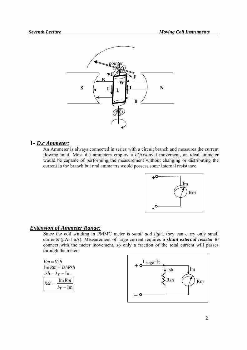
There are two types of moving coil instruments namely, permanent magnet moving coil type
which can only be used for direct current, voltage measurements and the dynamometer type which can be used on either direct or alternating current, voltage measurements. Permanent Magnet Moving Coil Mechanism (PMMC) In PMMC meter or (D’Arsonval) meter or galvanometer all are the same instrument, a coil of fine wire is suspended in a magnetic field produced by permanent magnet. According to the fundamental law of electromagnetic force, the coil will rotate in the magnetic field when it carries an electric current by electromagnetic (EM) torque effect. A pointer which attached the movable coil will deflect according to the amount of current to be measured which applied to the coil. The (EM) torque is counterbalance by the mechanical torque of control springs attached to the movable coil also. When the torques are balanced the moving coil will stopped and its angular deflection represent the amount of electrical current to be measured against a fixed reference, called a scale. If the permanent magnet field is uniform and the spring linear, then the pointer deflection is also linear. Mathematical Representation of PMMC Mechanism
Assume there are (N) turns of wire and the coil is (L) in long by (W) in wide. The force (F) acting perpendicular to both the direction of the current flow and the direction of magnetic field is given by:
LIBNF ⋅⋅⋅= where N: turns of wire on the coil I: current in the movable coil B: flux density in the air gap L: vertical length of the coil
Electromagnetic torque is equal to the multiplication of force with distance to the point of suspension
21
WNBILTI = in one side of cylinder 22
WNBILTI = in the other side of cylinder
The total torque for the two cylinder sides
NBIANBILWWNBILTI ==⎟⎠⎞
⎜⎝⎛=
22 where A: effective coil area
This torque will cause the coil to rotate until an equilibrium position is reached at an angle θ with its original orientation. At this position Electromagnetic torque = control spring torque TI = Ts Since Ts = Kθ
So IK
NBA=θ where
KNBAC = Thus CI=θ
The angular deflection proportional linearly with applied current
Seventh Lecture Moving Coil Instruments
2
1- D.c Ammeter: An Ammeter is always connected in series with a circuit branch and measures the current flowing in it. Most d.c ammeters employ a d’Arsonval movement, an ideal ammeter would be capable of performing the measurement without changing or distributing the current in the branch but real ammeters would possess some internal resistance.
Extension of Ammeter Range: Since the coil winding in PMMC meter is small and light, they can carry only small currents (μA-1mA). Measurement of large current requires a shunt external resistor to connect with the meter movement, so only a fraction of the total current will passes through the meter.
VshVm = IshRshRm =Im
Im−= TIIsh
ImIm−
=TI
RmRsh
S NB
B
F F
pointer
I I LW
Rm
Im +
-
Rm
Im +
_
Rsh
Ish
I range=IT
Seventh Lecture Moving Coil Instruments
3
Example: If PMMC meter have internal resistance of 10Ω and full scale range of 1mA.
Assume we wish to increase the meter range to 1A. Sol.
So we must connect shunt resistance with the PMMC meter of
Im
Im−
=TI
RmRsh Ω=×−
⋅×=
−
−01001.0
1011101013
3Rsh
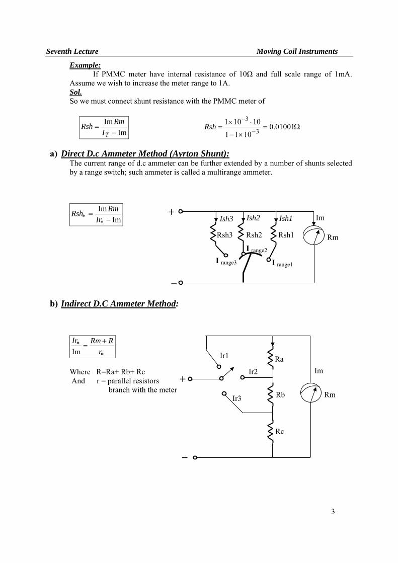
a) Direct D.c Ammeter Method (Ayrton Shunt):
The current range of d.c ammeter can be further extended by a number of shunts selected by a range switch; such ammeter is called a multirange ammeter.
ImIm−
=∗
∗ IrRmRsh
b) Indirect D.C Ammeter Method:
∗
∗ +=
rRRmIr
Im
Where R=Ra+ Rb+ Rc And r = parallel resistors branch with the meter
Rm
Im +
_
Rsh1
Ish1
I range1
Rsh2 Rsh3
Ish2 Ish3
I range3
I range2
Rm
Im +
_
Ra Ir1
Ir2
Ir3 Rb
Rc
Seventh Lecture Moving Coil Instruments
4
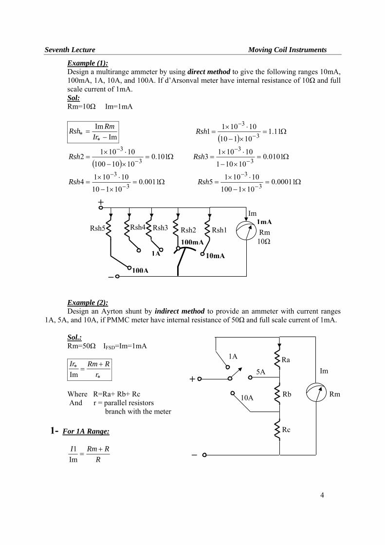
Example (1): Design a multirange ammeter by using direct method to give the following ranges 10mA, 100mA, 1A, 10A, and 100A. If d’Arsonval meter have internal resistance of 10Ω and full scale current of 1mA. Sol: Rm=10Ω Im=1mA
ImIm−
=∗
∗ IrRmRsh
( )Ω=
×−
⋅×=
−
−11.1
10110101011 3
3Rsh
( )Ω=
×−
⋅×=
−
−101.0
1010100101012 3
3Rsh Ω=
×−
⋅×=
−
−0101.0
10101101013 3
3Rsh
Ω=×−
⋅×=
−
−0011.0
10110101014 3
3Rsh Ω=
×−
⋅×=
−
−00011.0
101100101015 3
3Rsh
Example (2):
Design an Ayrton shunt by indirect method to provide an ammeter with current ranges 1A, 5A, and 10A, if PMMC meter have internal resistance of 50Ω and full scale current of 1mA. Sol.:
Rm=50Ω IFSD=Im=1mA
∗
∗ +=
rRRmIr
Im
Where R=Ra+ Rb+ Rc And r = parallel resistors branch with the meter
1- For 1A Range:
RRRmI +
=Im
1
+
Rm
Im
_
Rsh1
10mA
Rsh2 Rsh3
1A100mA
Rsh4 Rsh5
10Ω
100A
1mA
Rm
Im +
_
Ra 1A
5A
10A Rb
Rc
Seventh Lecture Moving Coil Instruments
5
RR
mAA +
=50
11 R=0.05005Ω
2- For 5A Range:
RcRbRRmI
++
=Im
2 r =Rb+Rc
RcRbmAA
++
=05005.050
15 Rb+Rc= 0.01001Ω
Ra=R-(Rb+Rc) Ra=0.05-0.01001=0.04004 Ω 3- For 10A Range:
RcRRmI +
=Im
3 r =Rc
RcmAA 05005.050
110 +
= Rc=5.005x10⁻³ Ω
Rb=0.01001-5.005x10-3= 5.005x10⁻³ Ω
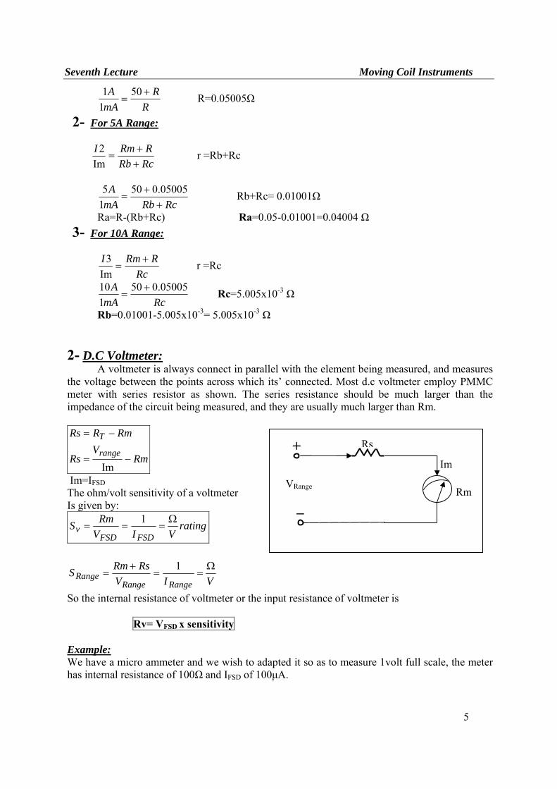
2- D.C Voltmeter: A voltmeter is always connect in parallel with the element being measured, and measures the voltage between the points across which its’ connected. Most d.c voltmeter employ PMMC meter with series resistor as shown. The series resistance should be much larger than the impedance of the circuit being measured, and they are usually much larger than Rm.
RmV
Rs
RmRRs
range
T
−=
−=
Im
Im=IFSD The ohm/volt sensitivity of a voltmeter Is given by:
ratingVIV
RmSFSDFSD
vΩ
===1
VIVRsRmS
RangeRangeRange
Ω==
+=
1
So the internal resistance of voltmeter or the input resistance of voltmeter is Rv= VFSD x sensitivity Example: We have a micro ammeter and we wish to adapted it so as to measure 1volt full scale, the meter has internal resistance of 100Ω and IFSD of 100μA.
Rm
Im +
_
Rs
VRange
Seventh Lecture Moving Coil Instruments
6
Sol.:
RmVRs −=Im
Ω=Ω=−= KRs 9.999001000001.01
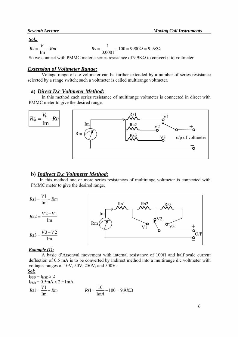
So we connect with PMMC meter a series resistance of 9.9KΩ to convert it to voltmeter Extension of Voltmeter Range:
Voltage range of d.c voltmeter can be further extended by a number of series resistance selected by a range switch; such a voltmeter is called multirange voltmeter. a) Direct D.c Voltmeter Method:
In this method each series resistance of multirange voltmeter is connected in direct with PMMC meter to give the desired range.
RmV
Rs −= ∗∗ Im
b) Indirect D.c Voltmeter Method:
In this method one or more series resistances of multirange voltmeter is connected with PMMC meter to give the desired range.
RmVRs −=Im
11
Im122 VVRs −
=
Im233 VVRs −
=
Example (1):
A basic d’Arsonval movement with internal resistance of 100Ω and half scale current deflection of 0.5 mA is to be converted by indirect method into a multirange d.c voltmeter with voltages ranges of 10V, 50V, 250V, and 500V. Sol: IFSD = IHSD x 2 IFSD = 0.5mA x 2 =1mA
RmVRs −=Im
11 Ω=−= KmA
Rs 9.91001101
Rm
Im +
_
Rs1 V1
V2
V3 o/p of voltmeter
Rs2
Rs3
Rm
Im
+
_
Rs1
V1
V2 V3
O/P
Rs2 Rs3
Seventh Lecture Moving Coil Instruments
7
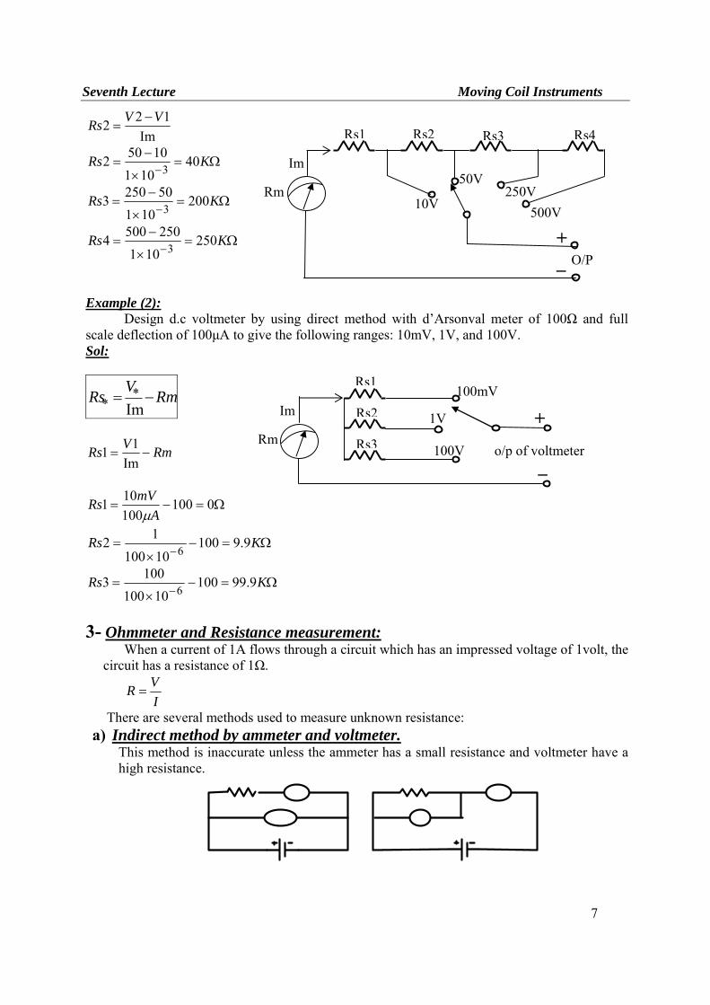
Im122 VVRs −
=
Ω=×
−=
−KRs 40
10110502 3
Ω=×
−=
−KRs 200
101502503 3
Ω=×
−=
−KRs 250
1012505004 3
Example (2): Design d.c voltmeter by using direct method with d’Arsonval meter of 100Ω and full scale deflection of 100μA to give the following ranges: 10mV, 1V, and 100V. Sol:
RmV
Rs −= ∗∗ Im
RmVRs −=Im
11
Ω=−= 0100100101
AmVRsμ
Ω=−×
=−
KRs 9.910010100
12 6
Ω=−×
=−
KRs 9.9910010100
1003 6
3- Ohmmeter and Resistance measurement:
When a current of 1A flows through a circuit which has an impressed voltage of 1volt, the circuit has a resistance of 1Ω.
IVR =
There are several methods used to measure unknown resistance: a) Indirect method by ammeter and voltmeter.
This method is inaccurate unless the ammeter has a small resistance and voltmeter have a high resistance.
Rm
Im
+_
Rs1
10V
50V 250V
O/P
Rs2 Rs3 Rs4
500V
Rm
Im +
_
Rs1100mV
1V
100V o/p of voltmeter
Rs2
Rs3
Seventh Lecture Moving Coil Instruments
8
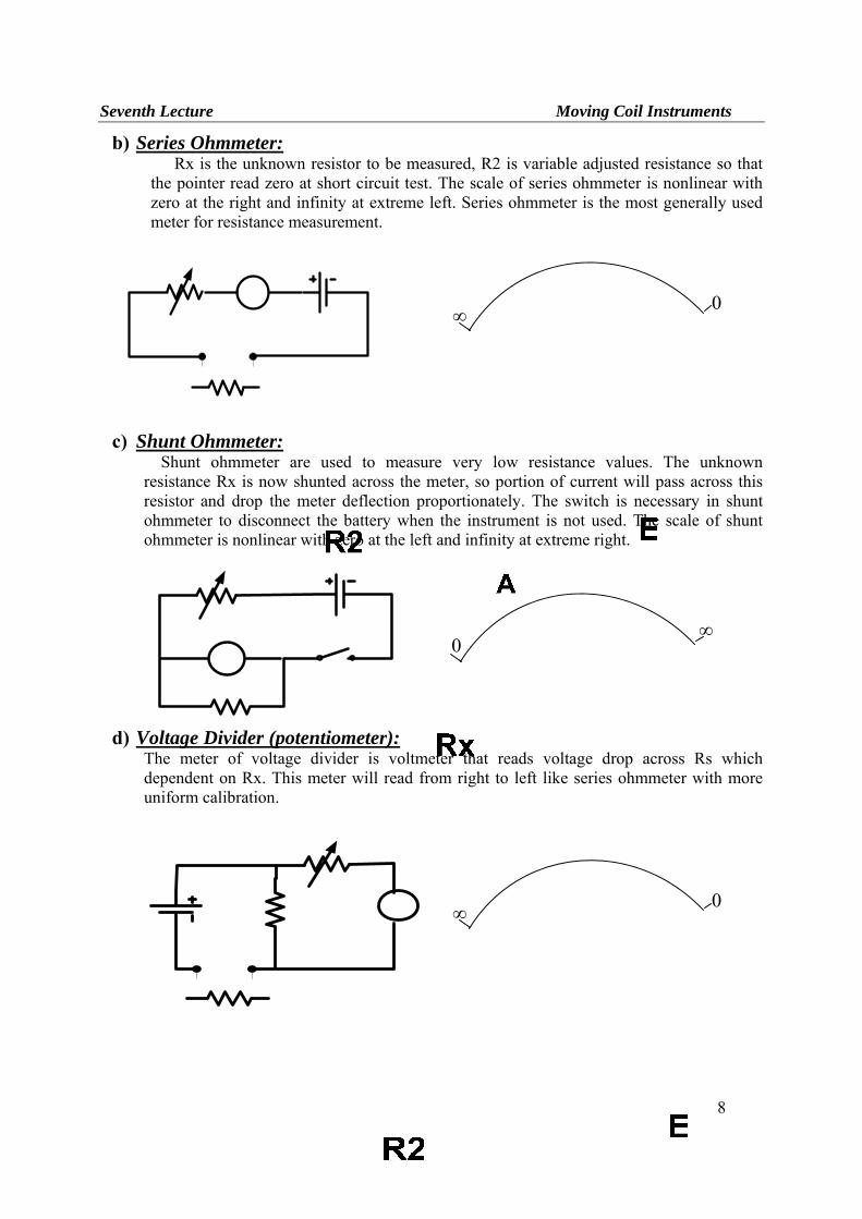
b) Series Ohmmeter: Rx is the unknown resistor to be measured, R2 is variable adjusted resistance so that
the pointer read zero at short circuit test. The scale of series ohmmeter is nonlinear with zero at the right and infinity at extreme left. Series ohmmeter is the most generally used meter for resistance measurement.
c) Shunt Ohmmeter:
Shunt ohmmeter are used to measure very low resistance values. The unknown resistance Rx is now shunted across the meter, so portion of current will pass across this resistor and drop the meter deflection proportionately. The switch is necessary in shunt ohmmeter to disconnect the battery when the instrument is not used. The scale of shunt ohmmeter is nonlinear with zero at the left and infinity at extreme right.
d) Voltage Divider (potentiometer):
The meter of voltage divider is voltmeter that reads voltage drop across Rs which dependent on Rx. This meter will read from right to left like series ohmmeter with more uniform calibration.
∞ 0
∞0
∞ 0