Embed Size (px)
Citation preview

MINUTES OF
IOWA DOT SPECIFICATION COMMITTEE MEETING
October 10, 2019 Members Present: Darwin Bishop District 3 - Construction Roger Boulet District 6 - Materials Mark Dunn Contracts & Specifications Bureau Daniel Harness Design Bureau Wes Musgrove Construction & Materials Bureau Mike Nop Bridges & Structures Bureau Tom Reis, Chair Contracts & Specifications Bureau Members Not Present: Donna Buchwald Local Systems Bureau Eric Johnsen, Secretary Contracts & Specifications Bureau Scott Nixon District 4 - Creston RCE Charlie Purcell Project Delivery Division Willy Sorensen Traffic & Safety Bureau Paul Wiegand SUDAS Advisory Members Present: Curtis Carter Construction & Materials Bureau Jeff DeVries Construction & Materials Bureau Robert Fangmann Cedar County Paul Geilenfeldt Marshall County Lisa McDaniel FHWA Melissa Serio Construction & Materials Bureau Others Present: Ken Brink Location & Environment Bureau Bill Eatock LaCrosse Seed Brad Weaver LaCrosse Seed The Specification Committee met on Thursday, October 10, 2019, at 9:00 a.m. in the NW Wing, 1st Floor Conference Room. Tom Reis, Specifications Engineer, opened the meeting. The items were discussed in accordance with the agenda dated September 30, 2019: The minutes are as follows: 1. Article 1101.03, Definition of Terms.
Article 1105.04, Conformity with and Coordination of the Contract Documents. The Design Bureau requested to add digital contract files to the Standard Specifications.

Agenda, Specification Committee Meeting, October 10, 2019, Page 2 of 31
2. Article 2403.02, B, 2, a, Structural Concrete. Article 2412.02, E, New Bridge Decks.
The Construction and Materials Bureau requested to adjust slump specifications and eliminate use of Type A Mid-Range water reducer. 3. Article 2513.03, A, 2, b, 1, Concrete Barrier. The Construction and Materials Bureau requested to eliminate the slump requirement for slip form barrier rail. 4. Article 2528.04, I, 2, b, Pilot Cars. The Construction and Materials Bureau requested to make measurement for pilot cars the same as flaggers, which was changed in 2018. 5. Article 2601.03, Erosion Control. The Design Bureau requested to revise drop seeder specifications and revise urban seeding mixes to match SUDAS seed mix. 6. Section 2611, Furnish and Install Shrubs and Trees with Warranty. The Design Bureau requested to clarify when initial installation is complete and establishment period begins. 7. Article 4123.03, Quality (Modified Subbase Material). The Office of Construction and Materials requested to revise the quality requirements for modified subbase. 8. Article 4196.01, B, 5, a, Subgrade Stabilization Material. The Office of Construction and Materials requested to update subgrade stabilization fabric and add a new option for material. 9. DS-15032, Mass Concrete (Control of Heat of Hydration). The Construction and Materials Bureau requested approval of revisions to DS-15032, Developmental Specifications for Mass Concrete (Control of Heat of Hydration).
10. DS-15071, High Performance Thin Lift Overlay. The Construction and Materials Bureau requested approval of revisions to DS-15071, Developmental Specifications for High Performance Thin Lift Overlay

Agenda, Specification Committee Meeting, October 10, 2019, Page 3 of 31
Form 510130 (08-15)
SPECIFICATION REVISION SUBMITTAL FORM
Submitted by: Mike Kennerly / Daniel Harness Office: Design Item 1
Submittal Date: 7-22-19 Proposed Effective Date: 4-21-20
Article No.: 1101.03 Title: Definition of Terms Article No.: 1105.04 Title: Conformity with and Coordination of the Contract Documents
Other:
Specification Committee Action: Deferred until a future meeting.
Deferred: X Not Approved: Approved Date: Effective Date:
Specification Committee Approved Text:
Comments: Following the meeting, the Design Bureau requested to withdraw this item for more discussion with other bureaus.
Specification Section Recommended Text: 1101.03, Definition of Terms.
Add to the definition of Contract (also Contract Documents): • Digital contract files specified in the contract documents.
1105.04, A. Add as a new number 4:
Digital Contract Files when included.
Renumber 4 through 10 as 5 through 11.
1105.04, D. Add as the last sentence:
Field adjustment of digital contract files, if necessary, will be completed by the Engineer. Comments:
Member’s Requested Change: (Do not use ‘Track Changes’, or ‘Mark-Up’. Use Strikeout and Highlight.) 1101.03, Definition of Terms.
Add to the definition of Contract (also Contract Documents): • Digital contract files specified in the contract documents.
1105.04, A. Add as a new number 4:
Digital Contract Files when included.
Renumber 4 through 10 as 5 through 11.
1105.04, D. Add as the last sentence:

Agenda, Specification Committee Meeting, October 10, 2019, Page 4 of 31
Field adjustment of digital contract files, if necessary, will be completed by the Engineer.
Reason for Revision: To include Special Provisions for Conformity with and Coordination of the Contract Documents in the Standard Specifications. This gives digital contract files, when included, precedence over the plans. The Design Bureau is developing an associated standard note that will be included in the plans.
New Bid Item Required (X one) Yes No X
Bid Item Modification Required (X one) Yes No X
Bid Item Obsoletion Required (X one) Yes No X
Comments:
County or City Comments:
Industry Comments:
Agenda, Specification Committee Meeting, October 10, 2019, Page 5 of 31
Form 510130 (08-15)
SPECIFICATION REVISION SUBMITTAL FORM
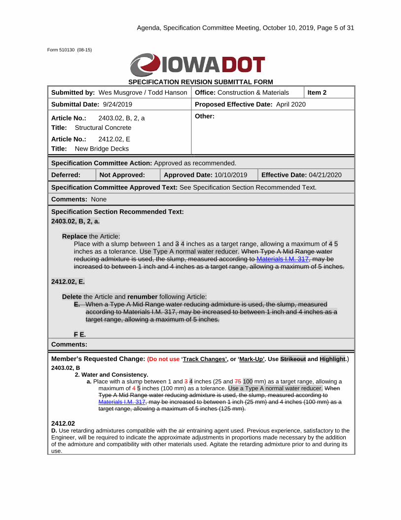
Submitted by: Wes Musgrove / Todd Hanson Office: Construction & Materials Item 2
Submittal Date: 9/24/2019 Proposed Effective Date: April 2020
Article No.: 2403.02, B, 2, a Title: Structural Concrete
Article No.: 2412.02, E Title: New Bridge Decks
Other:
Specification Committee Action: Approved as recommended.
Deferred: Not Approved: Approved Date: 10/10/2019 Effective Date: 04/21/2020
Specification Committee Approved Text: See Specification Section Recommended Text.
Comments: None
Specification Section Recommended Text: 2403.02, B, 2, a.
Replace the Article: Place with a slump between 1 and 3 4 inches as a target range, allowing a maximum of 4 5 inches as a tolerance. Use Type A normal water reducer. When Type A Mid Range water reducing admixture is used, the slump, measured according to Materials I.M. 317, may be increased to between 1 inch and 4 inches as a target range, allowing a maximum of 5 inches.
2412.02, E.
Delete the Article and renumber following Article: E. When a Type A Mid Range water reducing admixture is used, the slump, measured
according to Materials I.M. 317, may be increased to between 1 inch and 4 inches as a target range, allowing a maximum of 5 inches.
F E.
Comments:
Member’s Requested Change: (Do not use ‘Track Changes’, or ‘Mark-Up’. Use Strikeout and Highlight.) 2403.02, B
2. Water and Consistency. a. Place with a slump between 1 and 3 4 inches (25 and 75 100 mm) as a target range, allowing a
maximum of 4 5 inches (100 mm) as a tolerance. Use a Type A normal water reducer. When Type A Mid Range water reducing admixture is used, the slump, measured according to Materials I.M. 317, may be increased to between 1 inch (25 mm) and 4 inches (100 mm) as a target range, allowing a maximum of 5 inches (125 mm).
2412.02 D. Use retarding admixtures compatible with the air entraining agent used. Previous experience, satisfactory to the Engineer, will be required to indicate the approximate adjustments in proportions made necessary by the addition of the admixture and compatibility with other materials used. Agitate the retarding admixture prior to and during its use.

Agenda, Specification Committee Meeting, October 10, 2019, Page 6 of 31
E. When a Type A Mid Range water reducing admixture is used, the slump, measured according to Materials I.M. 317, may be increased to between 1 inch (25 mm) and 4 inches (100 mm) as a target range, allowing a maximum of 5 inches (125 mm).
E. F. Use a single source of cement during an individual placement. Drain all aggregate for at least 24 hours after washing and before batching.
Reason for Revision: Field experience has shown issues with too little water in the mix when mid range water reducers have been used causing issues with air entrainment. Admixture tech reps have also discussed this being an issue in the field. Follow in accordance with 2403 to allow slump to 5 inches and use a normal water reducer. Have seen issues with air entrainment in the field using mid range water reducer which is more pronounced with high dosages of retarders. May be leading to deck cracking.
New Bid Item Required (X one) Yes No x
Bid Item Modification Required (X one) Yes No x
Bid Item Obsoletion Required (X one) Yes No x
Comments:
County or City Comments:
Industry Comments: Industry agrees with change.

Agenda, Specification Committee Meeting, October 10, 2019, Page 7 of 31
Form 510130 (08-15)
SPECIFICATION REVISION SUBMITTAL FORM
Submitted by: Wes Musgrove / Todd Hanson Office: Construction & Materials Item 3
Submittal Date: September 6, 2019 Proposed Effective Date: April 2020
Article No.: 2513.03, A, 2, b, 1 Title: Concrete Barrier
Other:
Specification Committee Action: Approved as recommended.
Deferred: Not Approved: Approved Date: 10/10/2019 Effective Date: 04/21/2020
Specification Committee Approved Text: See Specification Section Recommended Text.
Comments: None
Specification Section Recommended Text: 2513.03, A, 2, b, 1.
Replace the Article: Water. Do not exceed Table 2513.03-2 for total mixing water and free moisture in the aggregate. Minimum slump is 1/2 inch.
Comments:
Member’s Requested Change: (Do not use ‘Track Changes’, or ‘Mark-Up’. Use Strikeout and Highlight.) 2. Cast-in-Place and Slip Form.
a. For cast-in-place, use Class C concrete complying with Materials I.M. 529. For slip form, use Class BR complying with Materials I.M. 529.
b. Submit Class BR mix design to the District Materials Engineer for approval at least 7 calendar days prior to placement. Apply Section 2403, except meet the following mix design requirements: 1) Water. Do not exceed Table 2513.03-2 for total mixing water and free moisture in the
aggregate. Minimum slump is 1/2 inch.
Reason for Revision: Slump is not needed for slip form barrier rail. Also, requires additional testing that is not necessary
New Bid Item Required (X one) Yes No x
Bid Item Modification Required (X one) Yes No x
Bid Item Obsoletion Required (X one) Yes No x
Comments:
County or City Comments:
Industry Comments:

Agenda, Specification Committee Meeting, October 10, 2019, Page 8 of 31
Form 510130 (08-15)
SPECIFICATION REVISION SUBMITTAL FORM
Submitted by: Wes Musgrove Office: Construction & Materials Item 4
Submittal Date: 8/30/2019 Proposed Effective Date: 4/21/2020
Article No.: 2528.04, I, Title: Pilot Cars
Other:
Specification Committee Action: Approved with changes.
Deferred: Not Approved: Approved Date: 10/10/2019 Effective Date: 04/21/2020
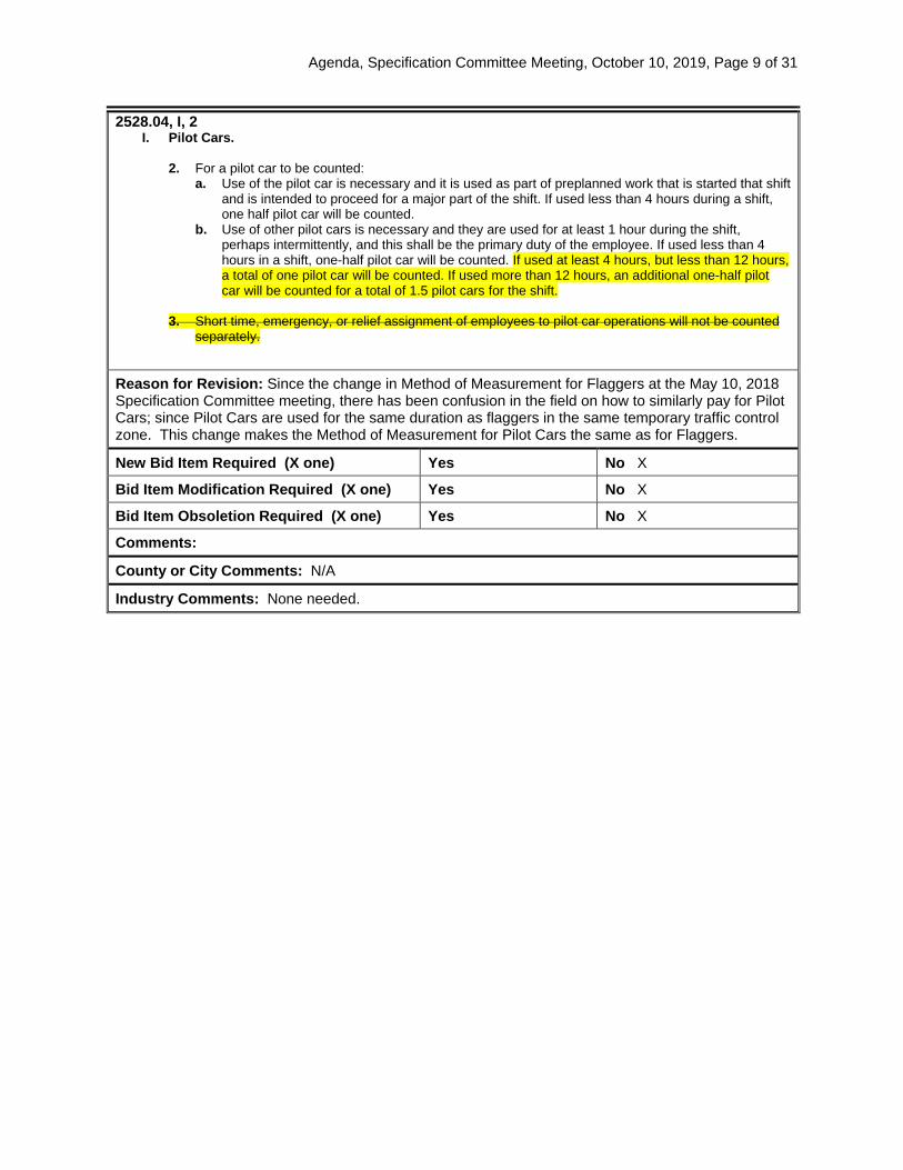
Specification Committee Approved Text: 2528.04, I, 2, b.
Add to the end of the Article: If used at least 4 hours, but less than 12 hours, a total of one pilot car will be counted. If used 12 hours or more, an additional one-half pilot car will be counted for a total of 1.5 pilot cars for the shift.
2528.04, I, Pilot Cars.
Delete the Article: 3. Short time, emergency, or relief assignment of employees to pilot car operations will not be
counted separately. 2528.04, J, 2, a.
Replace the Article:
Use of the flaggers is necessary and they are used as part of preplanned work that is started that shift and is intended to proceed for a major part of the shift. If used less than 4 hours during a shift, one-half flagger will be counted. If used at least 4 hours, but less than 12 hours, a total of one flagger will be counted. If used more than 12 hours or more, an additional one-half flagger will be counted for a total of 1.5 flaggers for the shift.
Comments: Approved with minor changes including a clarification to Article 2528.04, J, 2, a, to align the language for flaggers and pilot cars.
Specification Section Recommended Text: 2528.04, I, 2, b.
Add to the end of the Article: If used at least 4 hours, but less than 12 hours, a total of one pilot car will be counted. If used more than 12 hours, an additional one-half pilot car will be counted for a total of 1.5 pilot cars for the shift.
2528.04, I, Pilot Cars.
Delete the Article: 3. Short time, emergency, or relief assignment of employees to pilot car operations will not be
counted separately. Comments:
Agenda, Specification Committee Meeting, October 10, 2019, Page 9 of 31
2528.04, I, 2 I. Pilot Cars.
2. For a pilot car to be counted:
a. Use of the pilot car is necessary and it is used as part of preplanned work that is started that shift and is intended to proceed for a major part of the shift. If used less than 4 hours during a shift, one half pilot car will be counted.
b. Use of other pilot cars is necessary and they are used for at least 1 hour during the shift, perhaps intermittently, and this shall be the primary duty of the employee. If used less than 4 hours in a shift, one-half pilot car will be counted. If used at least 4 hours, but less than 12 hours, a total of one pilot car will be counted. If used more than 12 hours, an additional one-half pilot car will be counted for a total of 1.5 pilot cars for the shift.
3. Short time, emergency, or relief assignment of employees to pilot car operations will not be counted
separately.
Reason for Revision: Since the change in Method of Measurement for Flaggers at the May 10, 2018 Specification Committee meeting, there has been confusion in the field on how to similarly pay for Pilot Cars; since Pilot Cars are used for the same duration as flaggers in the same temporary traffic control zone. This change makes the Method of Measurement for Pilot Cars the same as for Flaggers.
New Bid Item Required (X one) Yes No X
Bid Item Modification Required (X one) Yes No X
Bid Item Obsoletion Required (X one) Yes No X
Comments:
County or City Comments: N/A
Industry Comments: None needed.
Agenda, Specification Committee Meeting, October 10, 2019, Page 10 of 31
Form 510130 (08-15)
SPECIFICATION REVISION SUBMITTAL FORM
Submitted by: Mike Kennerly Office: Design Item 5
Submittal Date: 9-20-19 Proposed Effective Date: April 2020 GS
Article No.: 2601.03 Title: Erosion Control
Other:
Specification Committee Action: Approved as recommended.
Deferred: Not Approved: Approved Date: 10/10/2019 Effective Date: 04/21/2020
Specification Committee Approved Text: See Specification Section Recommended Text.
Comments: None
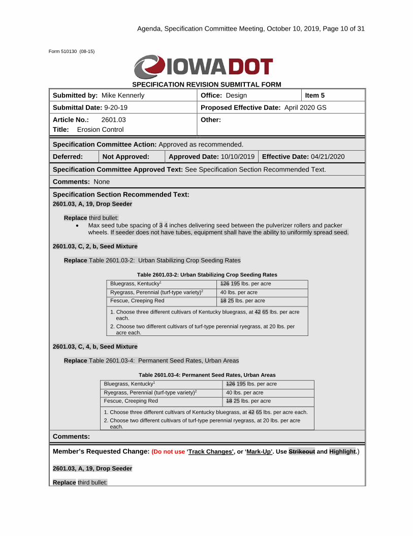
Specification Section Recommended Text: 2601.03, A, 19, Drop Seeder
Replace third bullet: • Max seed tube spacing of 3 4 inches delivering seed between the pulverizer rollers and packer
wheels. If seeder does not have tubes, equipment shall have the ability to uniformly spread seed. 2601.03, C, 2, b, Seed Mixture
Replace Table 2601.03-2: Urban Stabilizing Crop Seeding Rates
Table 2601.03-2: Urban Stabilizing Crop Seeding Rates Bluegrass, Kentucky1 126 195 lbs. per acre Ryegrass, Perennial (turf-type variety)2 40 lbs. per acre Fescue, Creeping Red 18 25 lbs. per acre
1. Choose three different cultivars of Kentucky bluegrass, at 42 65 lbs. per acre each.
2. Choose two different cultivars of turf-type perennial ryegrass, at 20 lbs. per acre each.
2601.03, C, 4, b, Seed Mixture
Replace Table 2601.03-4: Permanent Seed Rates, Urban Areas
Table 2601.03-4: Permanent Seed Rates, Urban Areas Bluegrass, Kentucky1 126 195 lbs. per acre Ryegrass, Perennial (turf-type variety)2 40 lbs. per acre Fescue, Creeping Red 18 25 lbs. per acre
1. Choose three different cultivars of Kentucky bluegrass, at 42 65 lbs. per acre each. 2. Choose two different cultivars of turf-type perennial ryegrass, at 20 lbs. per acre
each.
Comments:
Member’s Requested Change: (Do not use ‘Track Changes’, or ‘Mark-Up’. Use Strikeout and Highlight.) 2601.03, A, 19, Drop Seeder Replace third bullet:

Agenda, Specification Committee Meeting, October 10, 2019, Page 11 of 31
• Max seed tube spacing of 3 4 inches delivering seed between the pulverizer rollers and packer
wheels. If seeder does not have tubes, equipment must have the ability to uniformly spread seed.
2601.03, C, 2, b, Seed Mixture Replace Table 2601.03-2: Urban Stabilizing Crop Seeding Rates
Table 2601.03-2: Urban Stabilizing Crop Seeding Rates Bluegrass, Kentucky1 126 195 lbs. per acre Ryegrass, Perennial (turf-type variety)2 40 lbs. per acre Fescue, Creeping Red 18 25 lbs. per acre
1. Choose three different cultivars of Kentucky bluegrass, at 42 65 lbs. per acre each.
2. Choose two different cultivars of turf-type perennial ryegrass, at 20 lbs. per acre each.
2601.03, C, 4, b, Seed Mixture Replace Table 2601.03-4: Permanent Seed Rates, Urban Areas
Table 2601.03-4: Permanent Seed Rates, Urban Areas Bluegrass, Kentucky1 126 195 lbs. per acre Ryegrass, Perennial (turf-type variety)2 40 lbs. per acre Fescue, Creeping Red 18 25 lbs. per acre
1. Choose three different cultivars of Kentucky bluegrass, at 42 65 lbs. per acre each. 2. Choose two different cultivars of turf-type perennial ryegrass, at 20 lbs. per acre
each. Reason for Revision:
1) Clarify intent of specification and change requirement to match drop seeder equipment commonly available.
2) Revise urban seed mixes to match SUDAS seed mix.
New Bid Item Required (X one) Yes No x
Bid Item Modification Required (X one) Yes No x
Bid Item Obsoletion Required (X one) Yes No x
Comments: None
County or City Comments:
Industry Comments: Discussed change at 5/29/19 meeting with erosion control and landscaping contractors.

Agenda, Specification Committee Meeting, October 10, 2019, Page 12 of 31
Form 510130 (08-15)
SPECIFICATION REVISION SUBMITTAL FORM Submitted by: Mike Kennerly Office: Design Item 6
Submittal Date: 9-20-19 Proposed Effective Date: April 2020 GS
Article No.: 2611 Title: Furnish and Install Shrubs and Trees with Warranty
Other:
Specification Committee Action: Approved as recommended.
Deferred: Not Approved: Approved Date: 10/10/2019 Effective Date: 04/21/2020
Specification Committee Approved Text: See Specification Section Recommended Text.
Comments: None
Specification Section Recommended Text: 2611.03, F, 1, Plant Establishment Period and Replacement.
Replace second sentence: The establishment period will begin when the last tree and shrub plant of the initial installation is planted and incidental work related to the plantings is complete.
2611.05, D, 1
Retitle and Replace Article:
After Initial Installation of All Trees and Shrubs is Complete. Sixty-five percent of the placed quantity will be paid for all live plants of each size and variety installed with the specified mulch, and meeting the staking and guying requirements. This payment will be made after the initial inspection by the Engineer confirming all trees and shrubs are furnished and installed according to the contract documents.
Comments:
Member’s Requested Change: (Do not use ‘Track Changes’, or ‘Mark-Up’. Use Strikeout and Highlight.) 2611.03, F, 1, Plant Establishment Period and Replacement. Replace second sentence:
1. The plant establishment period will be the first two growing seasons. The establishment period will begin when the last tree and shrub plant of the initial installation is planted and incidental work related to the plantings is complete.
2611.05, D, 1 Retitle and Replace Article:
1. After Initial Installation of All Trees and Shrubs is Complete. Sixty-five percent of the placed quantity will be paid for all live plants of each size and variety installed with the specified mulch, and meeting the staking and guying requirements. This payment

Agenda, Specification Committee Meeting, October 10, 2019, Page 13 of 31
will be made after the initial inspection by the Engineer confirming all trees and shrubs are furnished and installed according to the contract documents.
Reason for Revision: Clarify when initial installation is complete and establishment period begins.
New Bid Item Required (X one) Yes No x
Bid Item Modification Required (X one) Yes No x
Bid Item Obsoletion Required (X one) Yes No x
Comments: None
County or City Comments:
Industry Comments: Discussed at 5/29/19 meeting with erosion control and landscaping contractors.
Agenda, Specification Committee Meeting, October 10, 2019, Page 14 of 31
Form 510130 (08-15)
SPECIFICATION REVISION SUBMITTAL FORM
Submitted by: Wes Musgrove / Bob Dawson Office: Construction & Materials Item 7
Submittal Date: 2019.09.19 Proposed Effective Date: April 2020 GS
Article No.: 4123.03 Title: Modified Subbase Material
Other:
Specification Committee Action: Approved as recommended.
Deferred: Not Approved: Approved Date: 10/10/2019 Effective Date: 04/21/2020
Specification Committee Approved Text: See Specification Section Recommended Text.
Comments: None
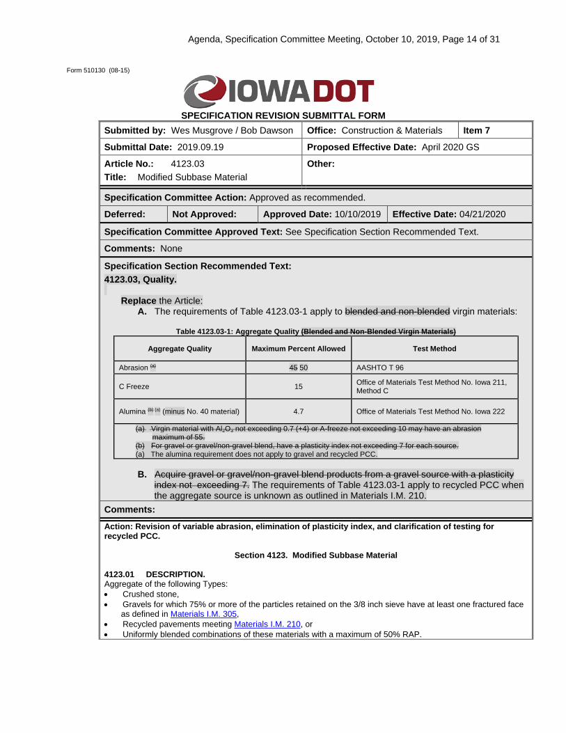
Specification Section Recommended Text: 4123.03, Quality.
Replace the Article: A. The requirements of Table 4123.03-1 apply to blended and non-blended virgin materials:
Table 4123.03-1: Aggregate Quality (Blended and Non-Blended Virgin Materials)
Aggregate Quality Maximum Percent Allowed Test Method
Abrasion (a) 45 50 AASHTO T 96
C Freeze 15 Office of Materials Test Method No. Iowa 211, Method C
Alumina (b) (a) (minus No. 40 material) 4.7 Office of Materials Test Method No. Iowa 222
(a) Virgin material with Al2O3 not exceeding 0.7 (+4) or A-freeze not exceeding 10 may have an abrasion maximum of 55.
(b) For gravel or gravel/non-gravel blend, have a plasticity index not exceeding 7 for each source. (a) The alumina requirement does not apply to gravel and recycled PCC.
B. Acquire gravel or gravel/non-gravel blend products from a gravel source with a plasticity
index not exceeding 7. The requirements of Table 4123.03-1 apply to recycled PCC when the aggregate source is unknown as outlined in Materials I.M. 210.
Comments:
Action: Revision of variable abrasion, elimination of plasticity index, and clarification of testing for recycled PCC.
Section 4123. Modified Subbase Material 4123.01 DESCRIPTION. Aggregate of the following Types: • Crushed stone, • Gravels for which 75% or more of the particles retained on the 3/8 inch sieve have at least one fractured face
as defined in Materials I.M. 305, • Recycled pavements meeting Materials I.M. 210, or • Uniformly blended combinations of these materials with a maximum of 50% RAP.

Agenda, Specification Committee Meeting, October 10, 2019, Page 15 of 31
4123.03 QUALITY.
A. The requirements of Table 4123.03-1 apply applies to blended and non-blended virgin materials:
Table 4123.03-1: Aggregate Quality (Blended and Non-Blended Virgin Materials)
Aggregate Quality Maximum Percent Allowed Test Method
Abrasion (a) 45 50 AASHTO T 96
C Freeze 15 Office of Materials Test Method No. Iowa 211, Method C
Alumina (b) (a) (minus No. 40 material) 4.7 Office of Materials Test Method No. Iowa 222
(a) Virgin material with Al2O3 not exceeding 0.7 (+4) or A-freeze not exceeding 10 may have an abrasion maximum of 55.
(b) For gravel or gravel/non-gravel blend, have a plasticity index not exceeding 7 for each source. (a) The alumina requirement does not apply to gravel and recycled PCC.
B. The requirements of Table 4123.03-1 apply to recycled PCC when the aggregate source is unknown as outlined in IM 210. B. Acquire gravel or gravel/non-gravel blend products from a gravel source with a plasticity index not
exceeding 7.
Reason for Revision: The variable abrasion is difficult to track and plasticity index is a soil test and was a poor test for non-plastic gravels.
New Bid Item Required (X one) Yes No x
Bid Item Modification Required (X one) Yes No x
Bid Item Obsoletion Required (X one) Yes No x
Comments:
County or City Comments:
Industry Comments: Reviewed and accepted by the Iowa Limestone Producers Association.
Agenda, Specification Committee Meeting, October 10, 2019, Page 16 of 31
Form 510130 (08-15)
SPECIFICATION REVISION SUBMITTAL FORM Submitted by: Wes Musgrove / Melissa Serio Office: Construction & Materials Item 8
Submittal Date: 9/20/19 Proposed Effective Date: April 2020 GS
Article No.: 4196.01, B, 5, a Title: Subgrade Stabilization Material
Other:
Specification Committee Action: Approved as recommended.
Deferred: Not Approved: Approved Date: 10/10/2019 Effective Date: 04/21/2020
Specification Committee Approved Text: See Specification Section Recommended Text.
Comments: None
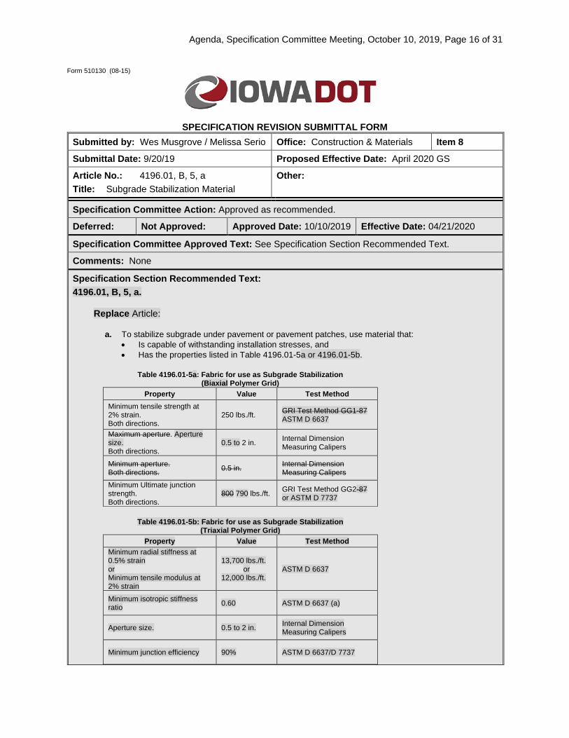
Specification Section Recommended Text: 4196.01, B, 5, a.
Replace Article:
a. To stabilize subgrade under pavement or pavement patches, use material that: • Is capable of withstanding installation stresses, and • Has the properties listed in Table 4196.01-5a or 4196.01-5b.
Table 4196.01-5a: Fabric for use as Subgrade Stabilization
(Biaxial Polymer Grid) Property Value Test Method
Minimum tensile strength at 2% strain. Both directions.
250 lbs./ft. GRI Test Method GG1-87 ASTM D 6637
Maximum aperture. Aperture size. Both directions.
0.5 to 2 in. Internal Dimension Measuring Calipers
Minimum aperture. Both directions. 0.5 in. Internal Dimension
Measuring Calipers Minimum Ultimate junction strength. Both directions.
800 790 lbs./ft. GRI Test Method GG2-87 or ASTM D 7737
Table 4196.01-5b: Fabric for use as Subgrade Stabilization
(Triaxial Polymer Grid) Property Value Test Method
Minimum radial stiffness at 0.5% strain or Minimum tensile modulus at 2% strain
13,700 lbs./ft. or
12,000 lbs./ft. ASTM D 6637
Minimum isotropic stiffness ratio 0.60 ASTM D 6637 (a)
Aperture size. 0.5 to 2 in. Internal Dimension Measuring Calipers
Minimum junction efficiency 90% ASTM D 6637/D 7737
Agenda, Specification Committee Meeting, October 10, 2019, Page 17 of 31
(a) Ratio between minimum and maximum values of radial stiffness at 0.5% strain, measured on rib and midway between rib directions.
Comments:
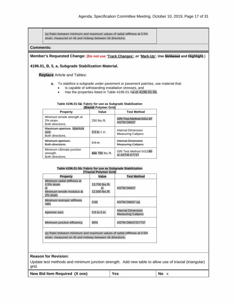
Member’s Requested Change: (Do not use ‘Track Changes’, or ‘Mark-Up’. Use Strikeout and Highlight.) 4196.01, B, 5, a, Subgrade Stabilization Material.
Replace Article and Tables:
a. To stabilize a subgrade under pavement or pavement patches, use material that: • Is capable of withstanding installation stresses, and • Has the properties listed in Table 4196.01-5a or 4196.01-5b.
Table 4196.01-5a: Fabric for use as Subgrade Stabilization (Biaxial Polymer Grid)
Property Value Test Method Minimum tensile strength at 2% strain. Both directions.
250 lbs./ft. GRI Test Method GG1-87 ASTM D6637
Maximum aperture. Aperture size. Both directions.
0.5 to 2 in. Internal Dimension Measuring Calipers
Minimum aperture. Both directions. 0.5 in. Internal Dimension
Measuring Calipers Minimum Ultimate junction strength. Both directions.
800 790 lbs./ft. GRI Test Method GG2-87 or ASTM D7737
Table 4196.01-5b: Fabric for use as Subgrade Stabilization (Triaxial Polymer Grid)
Property Value Test Method Minimum radial stiffness at 0.5% strain or Minimum tensile modulus at 2% strain
13,700 lbs./ft. or
12,000 lbs./ft. ASTM D6637
Minimum isotropic stiffness ratio 0.60 ASTM D6637 (a)
Aperture size. 0.5 to 2 in. Internal Dimension Measuring Calipers
Minimum junction efficiency 90% ASTM D6637/D7737
(a) Ratio between minimum and maximum values of radial stiffness at 0.5% strain, measured on rib and midway between rib directions.
Reason for Revision: Update test methods and minimum junction strength. Add new table to allow use of triaxial (triangular) grid.
New Bid Item Required (X one) Yes No x

Agenda, Specification Committee Meeting, October 10, 2019, Page 18 of 31
Bid Item Modification Required (X one) Yes No x
Bid Item Obsoletion Required (X one) Yes No x
Comments: None
County or City Comments:
Industry Comments:
Agenda, Specification Committee Meeting, October 10, 2019, Page 19 of 31
Form 510130 (08-15)
SPECIFICATION REVISION SUBMITTAL FORM Submitted by: Curtis Carter / Wes Musgrove Office: Construction & Materials Item 9
Submittal Date: 9/20/2019 Proposed Effective Date: 12/17/2019
Article No.: Title:
Other: DS-15032, Mass Concrete (Control of Heat of Hydration)
Specification Committee Action: Approved with minor revisions.
Deferred: Not Approved: Approved Date: 10/10/2019 Effective Date: 12/17/2019
Specification Committee Approved Text: See attached Developmental Specifications for Mass Concrete (Control of Heat of Hydration).
Comments: None.
Specification Section Recommended Text: See attached Draft Developmental Specifications for Mass Concrete (Control of Heat of Hydration).
Comments:
Member’s Requested Change: (Do not use ‘Track Changes’, or ‘Mark-Up’. Use Strikeout and Highlight.) Replace DS-15032 in its entirety with the new Developmental Specifications for Mass Concrete (Control of Heat of Hydration). This is a complete rewrite and as such, changes from the previous version are not shaded. Reason for Revision: This revised DS is being proposed as an update to the former DS-15032. This revision includes updates that standardize the method for determining an alternate allowable temperature difference limit based on the material properties of the specific concrete mix proposed, in response to requests by the construction industry. This re-write also includes new provisions specific to very large concrete placements and concrete placements in large bodies of water, and additional updates to keep the specification consistent with mass concrete best practices. New Bid Item Required (X one) Yes No X
Bid Item Modification Required (X one) Yes No X
Bid Item Obsoletion Required (X one) Yes No X
Comments:
County or City Comments:
Industry Comments:
Agenda, Specification Committee Meeting, October 10, 2019, Page 20 of 31
DS-15077 (Replaces DS-15032)
DEVELOPMENTAL SPECIFICATIONS FOR
MASS CONCRETE – CONTROL OF HEAT OF HYDRATION
Effective Date
December 17, 2019 THE STANDARD SPECIFICATIONS, SERIES 2015, ARE AMENDED BY THE FOLLOWING MODIFICATIONS AND ADDITIONS. THESE ARE DEVELOPMENTAL SPECIFICATIONS AND THEY SHALL PREVAIL OVER THOSE PUBLISHED IN THE STANDARD SPECIFICATIONS. Since this is a complete rewrite of the specification, revisions from DS-15032 are not shaded. 15077.01 DESCRIPTION.
A. Produce a mass concrete placement free of cracks caused or worsened by concrete heat of hydration. Accomplish this through appropriate concrete mix design and control of concrete temperatures and temperature differences. Use of concrete pre-cooling, concrete post-cooling, application of insulation or external heat, and/or selection of reduced heat of hydration concrete mix may be appropriate for this purpose.
B. Compliance may result in long durations of temperature control which could impact the sequence
and schedule of planned work. Implement procedures to control concrete temperature that are compatible with the work plan and project schedule.
C. Mass concrete is defined as concrete placement with a least dimension greater than 4.5 feet.
Mass concrete with a least dimension between 4.5 feet and 6.5 feet must satisfy Tier 1 temperature control plan requirements. Mass concrete with a least dimension greater than 6.5 feet must satisfy Tier 2 temperature control plan requirements. Tier 1 and Tier 2 temperature control plan requirements are defined in Article DS-15077.03, A. If any geometric portion of a placement qualifies as mass concrete, that entire placement shall be considered mass concrete. For example:
1. If a theoretical construction joint placed at any given location in the placement would result in
a fraction of the placement qualifying as mass concrete, that entire placement shall be considered mass concrete.
2. If a sphere of diameter 4.5 feet can fit somewhere within the bounds of the placement, the entire placement shall qualify as a Tier 1 mass concrete placement.
3. If a sphere of diameter exceeding 6.5 feet can fit somewhere within the bounds of the placement, the entire placement shall qualify as a Tier 2 mass concrete placement.
D. Do not apply this specification to concrete drilled shafts.
Agenda, Specification Committee Meeting, October 10, 2019, Page 21 of 31
E. Apply Section 2403 and Division 41 of the Standard Specifications with the following modifications.
15077.02 MATERIALS. Apply Section 2403 and Division 41 of the Standard Specifications.
15077.03 CONSTRUCTION.
A. Thermal Control Plan. 1. General.
a. Develop and submit a written Thermal Control Plan (TCP) to the Engineer describing procedures that will be used to maintain compliance with maximum temperature and maximum temperature difference requirements of Article DS-15077.03, B. TCP shall provide sufficient detail to demonstrate the Contractor has performed adequate planning to verify and control maximum temperature and maximum temperature difference for the full duration of thermal control. Submit TCP at least 30 calendar days before first intended structural mass concrete placement.
b. Do not place concrete covered by this specification until equipment and materials necessary to facilitate the plan are on site and ready for use, and TCP has received written approval by the Engineer.
c. Approval of TCP does not relieve Contractor from meeting the requirements of this specification.
2. Tier 1 Thermal Control Plan (concrete least dimension ≤ 6.5 feet).
For mass concrete placements with a least dimension less than or equal to 6.5 feet, Contractor shall provide a thermal control plan that includes, but is not limited to, the following: a. A listing of mass concrete placements addressed by TCP, including dimensions of each
placement. b. Approved concrete mix design. c. Limits for concrete temperature, including initial placement temperature, maximum
temperature after placement, and maximum temperature difference. d. Procedures to maintain initial concrete placement temperature within limits specified in
Article DS-15077.03, B. This may include pre-cooling of mix components, scheduling of placements to optimize ambient weather conditions, or other approved means.
e. Procedures to manage concrete temperature and temperature difference after placement, as may be necessary. This may include insulation of formwork and finished surfaces, external heating, or other approved means.
f. Procedures and equipment used to monitor concrete temperature and temperature difference in accordance with Article DS-15077.03, B, 5, including the location, quantity, and manufacturer’s product data for the temperature sensors.
g. Procedures for corrective intervention during the thermal control period (addition or extraction of heat, as feasible) for production concrete, should temperature monitoring indicate potential or confirmed non-compliance with the maximum temperature or maximum temperature difference limit specified in Article DS-15077.03, B.
3. Tier 2 Thermal Control Plan (concrete least dimension > 6.5 feet).
a. For mass concrete placements with a least dimension greater than 6.5 feet, TCP shall be developed by a Professional Engineer, licensed in the State of Iowa and competent in the modeling, design, and temperature control of concrete in mass elements (TC Engineer). TC Engineer shall formulate, implement, administer, and monitor TCP; adjusting as necessary to ensure compliance with the contract documents.
b. Use of thermal modeling shall be required. Thermal modeling shall predict temperature and temperature difference in mass concrete placements and estimate duration of thermal control. Thermal modeling shall consider the proposed thermal control measures
Agenda, Specification Committee Meeting, October 10, 2019, Page 22 of 31
and anticipated range of placement conditions and temperatures. c. At Contractor’s option, a Tier 2 TCP may be submitted for mass concrete placements
with least dimension less than or equal to 6.5 feet. d. Tier 2 TCP shall include all requirements of the Tier 1 TCP, in addition to the following:
1) A list containing at least three mass concrete projects, of similar dimension and thermal control requirements to those shown on the plans, completed by the TC Engineer in the last 3 years. List of projects shall include names and contact information of owner’s representatives who can verify the TC Engineer’s participation on those projects.
2) Calculated or measured adiabatic temperature rise of the concrete mix design. 3) Predicted maximum temperature in the mass concrete based on the expected
conditions at the time of placement and the use of proposed measures to control temperature.
4) Predicted maximum temperature difference in the mass concrete based on the expected conditions at the time of placement and the use of proposed measures to control temperature difference.
5) Details of proposed measures to control mass concrete temperature and temperature difference, consistent with the TC Engineer’s thermal model. Proposed measures shall be as needed to ensure compliance with maximum temperature and maximum temperature difference requirements.
6) Range of conditions, including concrete placement temperature range and ambient temperature range, for which the TCP is appropriate.
7) Estimated duration of thermal control. 8) For mass concrete placements within the limits of a meandered stream, design and
implementation of a post-cooling system in accordance with Article DS-15077.03, C, 3, for all mass concrete placements partially or wholly below water level. Meandered streams include rivers identified on DNR List of Meandered Streams, inclusive of reservoirs such meandered streams are tributary to.
B. Thermal Control Requirements.
1. Concrete Placement Temperature.
a. Concrete temperature at time of placement shall not exceed 70°F and shall not be less than 40°F.
b. Maximum concrete temperature at the time of placement may be modified by the TC Engineer, when supported by thermal analysis, in conjunction with a Tier 2 TCP. In no case shall maximum concrete temperature at time of placement exceed 90°F.
2. Maximum Concrete Temperature.
a. The maximum temperature within the mass concrete shall not exceed 160°F. b. The maximum temperature will be evaluated at each temperature sensor location placed
in accordance with Article DS-15077.03, B, 5 (includes standard, conditional and discretionary sensors, as applicable).
3. Temperature Difference Limit.
a. General. 1) Maximum temperature difference between interior of the section and surface of the
section shall not exceed specified limits. 2) Maximum temperature difference will be evaluated at each surface sensor location
placed in accordance with Article DS-15077.03, B, 5 (includes standard, conditional and discretionary sensors, as applicable). Temperature difference will be calculated as the difference between the temperature of the center of mass sensor and the temperature at each surface sensor location, respectively.
b. Mass concrete placements subject to Tier 1 and Tier 2 TCP requirements shall satisfy the temperature difference limits in the following table:

Agenda, Specification Committee Meeting, October 10, 2019, Page 23 of 31
Table DS-15077.03-1: Temperature Diff. Limits Hours after placement
Maximum temperature difference, °F
0-24 20 24-48 30 48-72 40
72 50
c. Alternate Temperature Difference Limit (ATD). 1) General.
a) Temperature difference limit may be modified by TC Engineer, when supported by thermal analysis, in conjunction with a Tier 2 TCP.
b) ATD shall be developed by the Contractor and TC Engineer using measured properties of the concrete mixture. Pre-development of a compressive strength maturity curve for the concrete mixture shall be required, in accordance with Materials I.M. 383. ATD shall only be considered valid for the specific mix tested. In the absence of a valid and approved ATD, the temperature difference limits of Article DS-15077.03, B, 3, a shall apply.
2) Required Pre-Testing to Develop the ATD. a) Contractor shall obtain test results using cylinders from the same batch of
concrete that are properly fabricated, cured at standard laboratory conditions, and are 14 to 56 days old at the time of testing.
b) Two cylinders will be tested in accordance with the current version of AASHTO T 336 (CTE). Three cylinders will be tested in accordance with the current version of ASTM C 496 (tensile strength). Three cylinders will be tested in accordance with the current version of ASTM C 469 (elastic modulus), and these cylinders will then be tested in accordance with ASTM C 39 (compressive strength). Testing shall be performed by an AASHTO-accredited laboratory with experience performing the listed test methods.
c) ASTM C 39, ASTM C 496, and ASTM C 469 testing shall be performed on the same day. Test reports shall include a statement from the laboratory that this requirement was met, and test reports shall be included with the TCP.
d) Laboratory shall report the individual and average value for each test method, and these averages shall be used in the calculations described in Article DS-15077.03, B, 3, b, 2). The strength and modulus shall be reported in units of psi (pounds per square inch) and CTE shall be in units of in./in./°F.
e) The following equations shall be used to determine the T-factor and E-factor to be used in accordance with Article DS-15077.03, B, 3, b, 2):
𝑇𝑇-𝑓𝑓𝑓𝑓𝑓𝑓𝑓𝑓𝑓𝑓𝑓𝑓 = 𝑓𝑓𝑡𝑡𝑓𝑓𝑐𝑐
𝐸𝐸-𝑓𝑓𝑓𝑓𝑓𝑓𝑓𝑓𝑓𝑓𝑓𝑓 = 𝐸𝐸�𝑓𝑓𝑐𝑐
Where: T-factor = tensile strength factor E-factor = elastic modulus factor 𝑓𝑓𝑐𝑐 = compressive strength (psi) 𝑓𝑓𝑡𝑡 = tensile strength (psi) 𝐸𝐸 = elastic modulus (psi)
Agenda, Specification Committee Meeting, October 10, 2019, Page 24 of 31
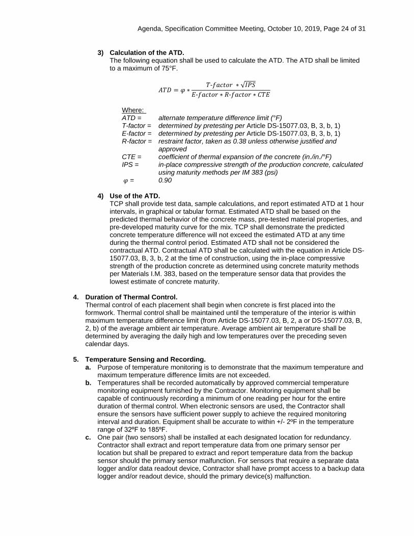
3) Calculation of the ATD. The following equation shall be used to calculate the ATD. The ATD shall be limited to a maximum of 75°F.
𝐴𝐴𝑇𝑇𝐴𝐴 = 𝜑𝜑 ∗𝑇𝑇-𝑓𝑓𝑓𝑓𝑓𝑓𝑓𝑓𝑓𝑓𝑓𝑓 ∗ √𝐼𝐼𝐼𝐼𝐼𝐼
𝐸𝐸-𝑓𝑓𝑓𝑓𝑓𝑓𝑓𝑓𝑓𝑓𝑓𝑓 ∗ 𝑅𝑅-𝑓𝑓𝑓𝑓𝑓𝑓𝑓𝑓𝑓𝑓𝑓𝑓 ∗ 𝐶𝐶𝑇𝑇𝐸𝐸
Where: ATD = alternate temperature difference limit (°F) T-factor = determined by pretesting per Article DS-15077.03, B, 3, b, 1) E-factor = determined by pretesting per Article DS-15077.03, B, 3, b, 1) R-factor = restraint factor, taken as 0.38 unless otherwise justified and
approved CTE = coefficient of thermal expansion of the concrete (in./in./°F) IPS = in-place compressive strength of the production concrete, calculated
using maturity methods per IM 383 (psi) 𝜑𝜑 = 0.90
4) Use of the ATD.
TCP shall provide test data, sample calculations, and report estimated ATD at 1 hour intervals, in graphical or tabular format. Estimated ATD shall be based on the predicted thermal behavior of the concrete mass, pre-tested material properties, and pre-developed maturity curve for the mix. TCP shall demonstrate the predicted concrete temperature difference will not exceed the estimated ATD at any time during the thermal control period. Estimated ATD shall not be considered the contractual ATD. Contractual ATD shall be calculated with the equation in Article DS-15077.03, B, 3, b, 2 at the time of construction, using the in-place compressive strength of the production concrete as determined using concrete maturity methods per Materials I.M. 383, based on the temperature sensor data that provides the lowest estimate of concrete maturity.
4. Duration of Thermal Control.
Thermal control of each placement shall begin when concrete is first placed into the formwork. Thermal control shall be maintained until the temperature of the interior is within maximum temperature difference limit (from Article DS-15077.03, B, 2, a or DS-15077.03, B, 2, b) of the average ambient air temperature. Average ambient air temperature shall be determined by averaging the daily high and low temperatures over the preceding seven calendar days.
5. Temperature Sensing and Recording. a. Purpose of temperature monitoring is to demonstrate that the maximum temperature and
maximum temperature difference limits are not exceeded. b. Temperatures shall be recorded automatically by approved commercial temperature
monitoring equipment furnished by the Contractor. Monitoring equipment shall be capable of continuously recording a minimum of one reading per hour for the entire duration of thermal control. When electronic sensors are used, the Contractor shall ensure the sensors have sufficient power supply to achieve the required monitoring interval and duration. Equipment shall be accurate to within +/- 2ºF in the temperature range of 32ºF to 185⁰F.
c. One pair (two sensors) shall be installed at each designated location for redundancy. Contractor shall extract and report temperature data from one primary sensor per location but shall be prepared to extract and report temperature data from the backup sensor should the primary sensor malfunction. For sensors that require a separate data logger and/or data readout device, Contractor shall have prompt access to a backup data logger and/or readout device, should the primary device(s) malfunction.
Agenda, Specification Committee Meeting, October 10, 2019, Page 25 of 31
d. Required number of temperature sensors shall be dependent on the mass concrete placement size, location and boundary conditions. Most mass concrete placements will utilize four pairs (eight total) of temperature sensors placed in accordance with Article DS-15077.03, B, 5, a. Mass concrete elements with large volume, potential for water inundation, or other circumstances identified by the Engineer shall merit the placement of additional sensor pairs. Contractor shall apply and maintain thermal control measures in a uniform and consistent manner across the entirety of the concrete element, such that surfaces and locations without temperature sensors are sufficiently represented by surfaces and locations with temperature sensors, to the TC Engineer’s and Engineer’s satisfaction.
e. Temperature sensors (one pair at each location) shall be installed in accordance with the following: 1) Standard Sensor Locations.
• Center of mass of the placement • Midpoint of the side surface or top surface which is the shortest distance from the
center of mass (2 inch to 4 inch cover) • Midpoint of the side surface or top surface with is the second-shortest distance
from the center of mass (2 inch to 4 inch cover) • Ambient air temperature. Ambient air temperature sensors shall be located at the
project site, in a fully shaded location near the mass concrete placement, away from artificial sources of heat.
2) Conditional Sensor Locations. • For mass concrete placements exceeding 400 cubic yards volume, provide one
additional pair of temperature sensors per each 400 cubic yard interval of concrete placed. The location of the sensor pair(s) shall be recommended in the TCP by the TC Engineer, subject to the Engineer’s approval.
• For Tier 2 mass concrete placements within the limits of a meandered stream, as identified by the DNR, provide two additional pairs of temperature sensors for monitoring potential effects of water inundation. One pair of sensors shall be placed on the side surface which is the shortest distance from the center of mass, and one pair of sensors shall be placed on the side surface which is second-shortest distance from the center of mass. The sensor pairs shall be centered horizontally within the side surface and shall be positioned vertically 12 inches from the bottom of the concrete placement (2 inch to 4 inch cover).
• For mass concrete placements for which post-cooling is utilized, provide two additional pairs of temperature sensors for monitoring the temperature of the cooling water. One pair of sensors shall be placed to monitor water temperature at the inlet of the cooling pipe system, and one pair of sensors shall be placed to monitor water temperature at the outlet of the cooling pipe system.
3) Discretionary Sensor Locations. In circumstances where TC Engineer or Engineer deems the prescribed standard sensor locations may be insufficient for monitoring the concrete placement, the Engineer may direct placement of up to 3 additional pairs of temperature sensors, paid in accordance with Article DS-15077.05. The discretionary sensors are intended for areas of the concrete placement that may be subject to unique boundary conditions or may otherwise be unrepresented by the standard temperature sensors. The Engineer shall provide Contractor notice of the location and quantity of discretionary sensors at least 2 days in advance of the scheduled mass concrete placement.
C. Production Concrete.
1. General.
a. Place mass concrete in accordance with the contract documents and the approved TCP. Use only the approved concrete mix design identified in the TCP. The location of

Agenda, Specification Committee Meeting, October 10, 2019, Page 26 of 31
construction joints shall be as shown in the plans. b. No work will be allowed on a concrete element while it is in thermal control, unless a plan
for maintaining the specified temperature difference limit during such work is submitted and approved.
2. Pre-cooling of Concrete
Pre-cooling of the concrete mix or mix components may be permitted using approved methods. Approved methods may include pre-wetting or pre-cooling of mix components, substitution of cubed or flaked ice for mix water, and/or use of liquid nitrogen. Use of dry ice shall not be permitted to pre-cool concrete. Designate the methods of pre-cooling in the TCP, if applicable.
3. Post-cooling of Concrete
a. Post-cooling (cooling pipes embedded in the mass concrete elements) shall be required for Tier 2 mass concrete placements within the limits of a meandered stream, as defined by the DNR. The primary purpose of mandatory post-cooling is to expedite the duration of thermal control and minimize the placement’s exposure to thermal shock resulting from unintended or unforeseen water inundation.
b. Post-cooling may be used in other concrete placements at the Contractor’s option, for purposes of controlling maximum concrete temperature or temperature difference and/or expediting the duration of thermal control.
c. For mass concrete placements with cooling pipes, the temperature sensors in the concrete placement shall remain near the locations specified in Article DS-15077.03, B, 5 but shall be shifted to be midway between the nearby cooling pipes. Concrete cover to the sensor shall remain 2 to 4 inches as specified in Article DS-15077.03, B, 5.
d. For mass concrete placements which require the use of cooling pipes in accordance with Article DS-15077.03, C, 3, a, the following requirements shall apply. The TC Engineer may propose modification to these requirements in situations where cooling pipes are used at the Contractor’s option in accordance with Article DS-15077.03, C, 3, b: • Cooling pipes shall consist of small diameter (3/4 or 1 inch) plastic pipe. • Cooling pipes shall be uniformly spaced throughout the mass concrete placement. A
minimum of 3.0 linear feet of cooling pipe shall be installed per each cubic yard of concrete.
• Joints between sections of pipe should be outside the concrete, when feasible. Pipe joints located within the concrete mass shall be detailed in the TCP and shall be subject to the Engineer’s approval.
• Cooling water shall constantly flow through the cooling pipes during the entire duration of thermal control.
• Flow rate of cooling water shall not be less than 3.0 gallons per minute in each cooling pipe. Higher flow rates may be required to achieve adequate cooling.
• Do not allow the cooling water in the cooling pipe system to freeze. When using water from a natural source, take measures to avoid blockage of pumps and pipes with debris/silt. Such measures may include debris guards, screens, or other means.
• Temperature rise of the water in the cooling pipes, from entry to exit, shall not exceed 3°F. Use multiple shorter cooling pipe loops rather than fewer longer cooling pipe loops.
• Use cooling water of a consistent temperature. Do not permit the cooling water to change in temperature by more than 20°F per hour. Do not use cooling water that is colder than 33°F or warmer than 90°F.
• Pipe-to-surface spacing shall be less than the pipe-to-pipe spacing. • Cooling pipes shall have valves to regulate the flow of cooling water. • Protect cooling pipes from damage during the placement of concrete. Have repair
materials on site for use, as needed. • Obtain permits, where necessary, for using hydrant or natural water as cooling water
in the cooling pipes.
Agenda, Specification Committee Meeting, October 10, 2019, Page 27 of 31
• Where practical, route cooling pipes into and out of the concrete placement through construction joints. Use blockouts to facilitate patching where pipes penetrate other surfaces.
4) After thermal control is complete: • Flush cooling pipes with fresh water if the cooling water contained glycol. Properly
dispose of such materials. • Inject cooling pipes with an approved non-shrink grout. • If cooling pipes penetrate a finished surface, cut-off cooling pipes 4 in. below the
surface and patch the surface with an approved non-shrink patching material. For surfaces visible to the public, patching material shall be of consistent color and general aesthetic compatibility with the mass concrete element.
4. Insulation.
When insulation is used, insulation shall be uniformly installed on each surface that requires insulation. Do not allow water or wind to compromise the effectiveness of the insulation.
5. External Heating.
If external heat must be applied, apply heat uniformly across the entire surface. Do not concentrate heat. Do not allow any portion of the surface to become warmer than the interior temperature. Designate the details and methods of external heating in the TCP, if applicable.
D. Temperature Reporting.
1. Recording of temperature data shall begin at the initiation of thermal control, and shall
continue until the completion of thermal control, as defined in Article DS-15077.03, B, 4. Recorded temperature data shall be reviewed by a representative of the Contractor at intervals not exceeding 8 hours. A copy of all recorded temperature data shall be furnished to the Engineer as the information is obtained.
2. A final report shall be furnished to the Engineer within 7 calendar days of completion of monitoring for each mass concrete placement. The final report shall include, but not be limited to the following: a. All measured hourly temperature data (time, date and temperature) from each
temperature sensor, in tabular format. b. Identification and location of each temperature sensor. c. A single graph showing the time versus temperature data for each temperature sensor
location within the placement, for the full duration of thermal control. The maximum temperature limit shall also be shown on the graph.
d. A single graph showing the time versus temperature difference data, calculated in accordance with Article DS-15077.03, B, 3, for the full duration of thermal control. The maximum temperature difference limit shall also be shown on the graph.
e. A statement of whether the maximum temperature and/or temperature difference limit was exceeded. If the maximum temperature and/or temperature difference limit was exceeded, indicate at what time(s) and at what sensor location(s).
E. Corrective Actions.
1. If the temperature or temperature difference within the mass concrete placement exceeds the
limits of this specification, corrective action shall be taken by the Contractor. Immediate steps shall be taken to bring the concrete element back into compliance with temperature requirements, as feasible and as recommended by the TC Engineer. Future placement of mass concrete shall be suspended, and a revised TCP shall be submitted to the Engineer for approval. Do not resume placement of mass concrete without written approval from the Engineer.
2. Following completion of thermal control for any mass concrete element that exceeds
Agenda, Specification Committee Meeting, October 10, 2019, Page 28 of 31
specification limits for maximum temperature or temperature difference, an investigation plan shall be developed and implemented by the Contractor and TC Engineer, subject to the Engineer’s approval. The investigation plan shall assess whether the non-compliant temperature or temperature difference may have impacted the structural integrity or durability of the mass concrete element.
3. A corrective action plan shall be proposed by the Contractor and TC Engineer, based on the results of the investigation. Final determination of corrective actions shall be by the Engineer which may include, but shall not be limited to price adjustment, epoxy injection of cracks, a combination of both, or removal of the non-complying concrete. The cost of investigation and corrective action shall be borne by the Contractor. No compensation of time or expense will be granted by the Contracting Authority for investigation or correction of non-compliant mass concrete elements.
15077.04 METHOD OF MEASUREMENT.
A. Protection of mass concrete shall be included in the contract unit price for Structural Concrete.
B. Measurement of discretionary temperature sensors shall be by count for each installed, for sensors placed at the direction of the Engineer in accordance with Article DS-15077,03, B, 5, c. Other temperature sensors will not be measured for payment.
15077.05 BASIS OF PAYMENT.
A. Article 2403.05, A, 4 of the Standard Specifications shall not apply to mass concrete. Protection of mass concrete shall be included in the contract unit price for Structural Concrete.
B. For discretionary temperature sensors placed at the direction of the Engineer in accordance with
Article DS-15077,03, B, 5, c, payment will be a price of $500 each per sensor. Payment is full compensation for all labor, material and equipment for placement and operation of the sensor, and processing and reporting of the sensor data.
Agenda, Specification Committee Meeting, October 10, 2019, Page 29 of 31
Form 510130 (08-15)
SPECIFICATION REVISION SUBMITTAL FORM
Submitted by: Wes Musgrove / Jeff Schmitt Office: Construction & Materials Item 10
Submittal Date: 9-20-2019 Proposed Effective Date: 12/17/2019
Article No.: Title:
Other: DS-15071, Developmental Specifications for High Performance Thin Lift Overlay
Specification Committee Action: Approved as recommended.
Deferred: Not Approved: Approved Date: 10/10/2019 Effective Date: 12/17/2019
Specification Committee Approved Text: See attached Developmental Specifications for High Performance Thin Lift Overlay.
Comments: None
Specification Section Recommended Text: See attached Draft Developmental Specifications for High Performance Thin Lift Overlay.
Comments:
Member’s Requested Change: (Do not use ‘Track Changes’, or ‘Mark-Up’. Use Strikeout and Highlight.) 150XX.02 MATERIALS. B. Mix Design.
1. Design Gyrations 50 Design Voids Target (Based on %Gmm) < 2.0 Film Thickness 8.0 – 13.0 15.0
Reason for Revision: Change the specified maximum asphalt binder film thickness (FT) from 13.0 to 15.0 microns. This revision, recommended by Scott Schram, brings the maximum FT in-line with other asphalt mixtures. The revision also helps solve the unintended consequence of binder-rich/low void high-performance mixes exceeding the (relatively low) 13.0 spec. limit, a carryover from 100M ESAL mixes.
New Bid Item Required (X one) Yes No X
Bid Item Modification Required (X one) Yes No X
Bid Item Obsoletion Required (X one) Yes No X
Comments: This revision was recommended for approval by DME’s at their 9-11-2019 meeting.
County or City Comments:
Industry Comments:
Agenda, Specification Committee Meeting, October 10, 2019, Page 30 of 31
DS-15078 (Replaces DS-15071)
DEVELOPMENTAL SPECIFICATIONS
FOR HIGH PERFORMANCE THIN LIFT OVERLAY
Effective Date December 17, 2019
THE STANDARD SPECIFICATIONS, SERIES 2015, ARE AMENDED BY THE FOLLOWING MODIFICATIONS AND ADDITIONS. THESE ARE DEVELOPMENTAL SPECIFICATIONS AND THEY PREVAIL OVER THOSE PUBLISHED IN THE STANDARD SPECIFICATIONS. 15078.01 DESCRIPTION. These specifications describe requirements for a highly polymer modified asphalt thin lift surface course. Apply Section 2303 of the Standard Specifications unless otherwise directed in these specifications. 15078.02 MATERIALS.
A. Asphalt Binder. Use PG 64-34E+ with a minimum percent recovery of 90% when tested at 64°C per AASHTO T 350 at 3.2 kPa.
B. Mix Design. 1. Design Gyrations 50
Design Voids Target (Based on %Gmm) ≤ 2.0 Film Thickness 8.0 – 13.0 15.0 Aggregate Quality A Crushed Content (minimum) 50% FAA (minimum) 40 Sand Equivalency (minimum) 50
2. Friction Aggregate. Interstates: minimum 30% of Total Aggregate shall be Type 2 or better Non-Interstates: minimum 50% of Total Aggregate shall be Type 4 or better
3. Hamburg Testing (AASHTO T324). Compact to 3.5% air voids. No more than 4 mm rutting in the first 8000 passes.
4. Do not use more than 15.0% binder replacement. Do not use RAS.

Agenda, Specification Committee Meeting, October 10, 2019, Page 31 of 31
5. Gradation.
Table DS-15078: Thin Lift Overlay Gradation Sieve Size Min % Passing Max % Passing 1½ inch 1 inch 3/8 inch 91 100 #4 90 #8 27 63 #16 #30 #50 #100 #200 2 10
15078.03 CONSTRUCTION.
A. Apply tack coat prior to placement of thin lift overlay according to Section 2303 of the Standard Specifications.
B. Pave when ambient temperatures are at least 60ºF and rising.
C. Compact with static steel wheeled roller.
D. Do not open to traffic until the entire mat has cooled below 150°F.
E. Quality Assurance/Quality Control.
1. Field Voids Acceptance.
Acceptance for field voids shall be Class II compaction defined in Section 2303 of the Standard Specifications.
2. Lab Voids Acceptance.
Sample from windrow or hopper. Apply Article 2303.05, A, 3, a, 2, of the Standard Specifications for AAD acceptance. Air void target is based on approved JMF.
3. Take at least one cold feed for gradation control each day of production.
15078.04 METHOD OF MEASUREMENT. Hot Mix Asphalt Thin Lift Overlay will be measured according to Article 2303.04 of the Standard Specifications. 15078.05 BASIS OF PAYMENT. Hot Mix Asphalt Thin Lift Overlay will be paid for according to Article 2303.05 of the Standard Specifications.