Embed Size (px)
Citation preview

LAST UPDATE JULY 2013

MINNESOTA GO STATE AVIATION SYSTEM PLAN
Acknowledgements
The preparation of this document was financed in part by a grant from the Federal Aviation Administration (Project No: 3-27-0000-07-10), with the financial support of the MnDOT Office of Aeronautics. The contents do not necessarily reflect the official views or the policy of the FAA. Acceptance of this report does not in any way constitute a commitment to fund the development depicted herin.
Document prepared by MnDOT Office of Aeronautics and HNTB Corporation.

CHAPTER 5 AIRPORT FACILITY REQUIREMENTS
TABLE OF CONTENTS
Chapter 1: Introduction and System Goals 1
Chapter 2: Inventory 29
Chapter 3: Forecast 43
Chapter 4: Airline Service 63
Chapter 5: Airport Facility Requirements 75
Chapter 6: Performance Report 97
Chapter 7: Investment Plan and System Recommendations 161
Chapter 8: A Future Vision of Aviation 195
Appendices 215
Chapter 5: Airport Facility Requirements 75

MINNESOTA GO STATE AVIATION SYSTEM PLAN
This page intentionally left blank.

CHAPTER 5 AIRPORT FACILITY REQUIREMENTS 75PAGE
Chapter 5
AIRPORT FACILITY REQUIREMENTS

76 MINNESOTA GO STATE AVIATION SYSTEM PLANPAGE
This page intentionally left blank.
77CHAPTER 5 AIRPORT FACILITY REQUIREMENTS PAGE
AIRPORT FACILITY REQUIREMENTSThis chapter outlines the state’s airport facility requirements necessary to accommodate aviation demand in Minnesota over the next 20 years as well as the processes and assumptions used to analyze them. Airport facility requirements are useful in planning how to expend anticipated revenues and are identified through consideration of an individual airport’s existing facilities (Chapter 2: Inventory), airport activity forecasts (Chapter 3: Forecast), and certain minimum objectives established for the system (Table 5-2). This method allows for a relatively uniform analysis across the system that stops short of addressing the specific project needs of individual airports (e.g. runway extension to a specific length). It is important to note that the airport facility requirements analysis does not replace the need for individual project planning efforts or project justification reports. Rather, it provides a macro-level snap-shot of the system through short-term, mid-term, and long-term planning horizons.
Table 5-1 identifies the major airport facilities that are accounted for in this requirements analysis and are presented following description of minimum system objectives.
These facilities represent the major cost items associated with an airport’s development. While, maintenance of pavements and terminal/administration buildings also consume significant financial resources, they are discussed separately in Chapter 7: Investment Plan and System Recommendations.
Table 5-1: Major Airport Facilities
Airport Pavements
Navigation Systems
Runway Lighting
Weather Reporting Systems
Airport Buildings
Fuel Facilities
78 MINNESOTA GO STATE AVIATION SYSTEM PLANPAGE
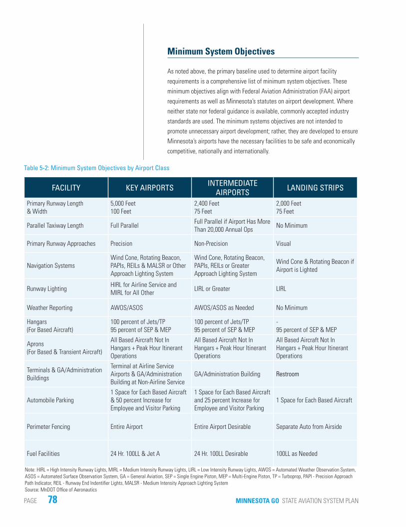
Minimum System Objectives
As noted above, the primary baseline used to determine airport facility requirements is a comprehensive list of minimum system objectives. These minimum objectives align with Federal Aviation Administration (FAA) airport requirements as well as Minnesota’s statutes on airport development. Where neither state nor federal guidance is available, commonly accepted industry standards are used. The minimum systems objectives are not intended to promote unnecessary airport development; rather, they are developed to ensure Minnesota’s airports have the necessary facilities to be safe and economically competitive, nationally and internationally.
FACILITY KEY AIRPORTS INTERMEDIATE AIRPORTS LANDING STRIPS
Primary Runway Length & Width
5,000 Feet100 Feet
2,400 Feet75 Feet
2,000 Feet75 Feet
Parallel Taxiway Length Full Parallel Full Parallel if Airport Has More Than 20,000 Annual Ops No Minimum
Primary Runway Approaches Precision Non-Precision Visual
Navigation SystemsWind Cone, Rotating Beacon, PAPIs, REILs & MALSR or Other Approach Lighting System
Wind Cone, Rotating Beacon, PAPIs, REILs or Greater Approach Lighting System
Wind Cone & Rotating Beacon if Airport is Lighted
Runway Lighting HIRL for Airline Service and MIRL for All Other LIRL or Greater LIRL
Weather Reporting AWOS/ASOS AWOS/ASOS as Needed No Minimum
Hangars(For Based Aircraft)
100 percent of Jets/TP95 percent of SEP & MEP
100 percent of Jets/TP95 percent of SEP & MEP
-95 percent of SEP & MEP
Aprons(For Based & Transient Aircraft)
All Based Aircraft Not In Hangars + Peak Hour Itinerant Operations
All Based Aircraft Not In Hangars + Peak Hour Itinerant Operations
All Based Aircraft Not In Hangars + Peak Hour Itinerant Operations
Terminals & GA/Administration Buildings
Terminal at Airline Service Airports & GA/Administration Building at Non-Airline Service
GA/Administration Building Restroom
Automobile Parking1 Space for Each Based Aircraft & 50 percent Increase for Employee and Visitor Parking
1 Space for Each Based Aircraft and 25 percent Increase for Employee and Visitor Parking
1 Space for Each Based Aircraft
Perimeter Fencing Entire Airport Entire Airport Desirable Separate Auto from Airside
Fuel Facilities 24 Hr. 100LL & Jet A 24 Hr. 100LL Desirable 100LL as Needed
Table 5-2: Minimum System Objectives by Airport Class
Note: HIRL = High Intensity Runway Lights, MIRL = Medium Intensity Runway Lights, LIRL = Low Intensity Runway Lights, AWOS = Automated Weather Observation System, ASOS = Automated Surface Observation System, GA = General Aviation, SEP = Single Engine Piston, MEP = Multi-Engine Piston, TP = Turboprop, PAPI - Precision Approach Path Indicator, REIL - Runway End Indentifier Lights, MALSR - Medium Intensity Approach Lighting SystemSource: MnDOT Office of Aeronautics
79CHAPTER 5 AIRPORT FACILITY REQUIREMENTS PAGE
Table 5-2 presents the minimum system objectives for each of Minnesota’s three airport classifications. A facility requirement exists when there is a gap between the major facilities an airport has, and the facilities the same airport is expected to have over the short-term, mid-term, and long-term given its activity forecast and the minimum system objectives for its airport class. The remainder of this chapter focuses on this aspect. When the facility requirements for all airports in Minnesota’s system are rolled up over all three planning periods, the result is the system’s overall needs in terms of cost. The overall system needs are further discussed and identified in Chapter 7: Investment Plan and System Recommendations.
Primary Runway Length and Width
An airport’s primary runway length and width are determined by the operational requirements of the airport’s critical aircraft. A critical aircraft is one that requires the greatest runway length and/or width for safe operations, and has or is forecasted to have over 500 annual operations at an individual airport. A high-level analysis of primary runway needs was completed using aircraft categories collected in the inventory and utilized to prepare the forecast.
A sample of the types of aircraft within each aircraft category was compiled and one representative aircraft for each category was chosen for the analysis. Minimum runway lengths were determined for the representative aircraft using FAA Advisory Circular (AC) 150/5325-4B which is used to determine appropriate runway length using aircraft performance metrics and airport characteristics.
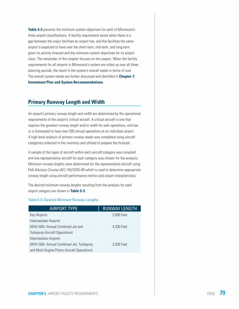
The desired minimum runway lengths resulting from the analysis for each airport category are shown in Table 5-3.
Table 5-3: Desired Minimum Runway Lengths
AIRPORT TYPE RUNWAY LENGTHKey Airports 5,000 Feet
Intermediate Airports (With 500+ Annual Combined Jet and Turboprop Aircraft Operations)
4,200 Feet
Intermediate Airports (With 500+ Annual Combined Jet, Turboprop, and Multi-Engine Piston Aircraft Operations)
3,200 Feet

80 MINNESOTA GO STATE AVIATION SYSTEM PLANPAGE
Airports in Table 5-4 have been identified as potentially needing a runway extension. These airports have forecast operations requiring additional runway length and are deficient of the minimum runway length by at least 250 feet, which is the minimal practical runway extension from a cost perspective. It is important to note that these runway extension needs are the result of a high-level analysis and the results cannot serve as justification for a runway extension project. An airport seeking a runway extension must work closely with MnDOT and the FAA to consider the economic, social, and environmental impacts of the project. Because extensions to 5,000 feet or greater result in reclassification of an airport from Intermediate to Key, upsizing complimentary facilities (e.g. full parallel taxiway, precision approach and others) to meet the minimum system objectives (Table 5-2) of Key Airports would be necessary. These facilities are also identified in Table 5-4 as well as on individual airport’s facility sheets in Appendix E: Airport Facility Needs Sheets and Report Cards. While it is reasonable to assume five airports will be reclassified from Intermediate to Key over the 20-year planning period, it is unlikely that it will be exactly the five identified by this macro-level analysis.
AIRPORT IDENTIFIER RUNWAY EXTENSION
RUNWAY WIDENING
RE-CLASSIFICATION
Airlake LVN X - X
Appleton AQP X - -
Blue Earth SBU X - -
Brooten 6D1 - X -
Crystal MIC X - -
Detroit Lakes DTL X - X
Faribault FBL - X -
Fertile D14 - X -
Granite Falls GDB X - X
Hector 1D6 - X -
Herman 06Y - X -
Lake Elmo 21D X - -
Maple Lake MGG X X -
Perham 16D X - X
Pine River PWC X - X
Red Lake Falls D81 - X -
Rushford 55Y - X -
Sauk Centre D39 - X -
Slayton DVP - X -
Sleepy Eye Y58 X - -
Stephen D41 X X -
Warren D37 X - -
Table 5-4: Airports with Primary Runway Needs
Source: MnDOT Office of Aeronautics 2011 Inventory Survey and Airport Database & HNTB Analysis

81CHAPTER 5 AIRPORT FACILITY REQUIREMENTS PAGE
Runway width requirements are defined by either FAA standards or MnDOT minimum objectives. The airports identified in Table 5-4 could qualify for a runway widening.
Maple Lake Municipal and Stephen Municipal are identified as being deficient in terms of both the length and width of their runway.
Parallel Taxiway Length
Parallel taxiways serve two primary purposes. First, they provide added safety by minimizing potential conflicts between taxiing aircraft and arriving or departing aircraft. Second, parallel taxiways increase runway capacity, particularly at busier airports because a landing or departing aircraft must wait to use the runway while it’s occupied by taxiing aircraft.
Only three airports were identified as potentially benefitting from a parallel taxiway within the next 20 years (see Table 5-5). One of those airports, Aitkin Municipal Airport, currently only has taxiway turnarounds on both runway ends, but has enough operations (> 20,000 annually) to warrant a full-length parallel taxiway. Both Detroit Lakes Municipal Airport and Faribault Municipal Airport have taxiways parallel to the runway for only a portion of its length, but have enough annual operations to warrant a full parallel taxiway.
AIRPORT IDENTIFIER
FULL- LENGTH
PARALLEL TAXIWAY
PARALLEL TAXIWAY
EXTENSION
Aitkin AIT X -
Detroit Lakes DTL - X
Faribault FBL - X
Table 5-5: Airports with Parallel Taxiway Needs
Source: MnDOT Office of Aeronautics 2011 Inventory Survey and Airport Database & HNTB Analysis

82 MINNESOTA GO STATE AVIATION SYSTEM PLANPAGE
Primary Runway Approaches
Runway approach procedures are designed to guide the transition from the cruise phase of a flight to the approach and landing phase. An instrument approach makes an airport useable under a wider variety of weather conditions than an airport without one. The purpose of including approaches as a minimum system objective is to improve access to airports during inclement weather. The minimum system objectives consider multiple approach types depending upon an airport’s classification.
The minimum system objective for Key Airports is to have a precision instrument approach procedure which guides the pilot vertically and horizontally for at least one end of the primary runway and a less precise approach with at least vertical guidance at the other end.
Intermediate Airports have less activity during inclement weather so the minimum system objective is less precise. These airports should have a non-precision instrument approach with vertical guidance on at least one runway end.
Figure 5-1: Minimum Approaches by Airport Classification
Source: HNTB

83CHAPTER 5 AIRPORT FACILITY REQUIREMENTS PAGE
Visual approaches are sufficient for most aircraft that use Landing Strip airports. With the advent of GPS based approaches, some landing strips may choose to provide a non-precision approach.
Figure 5-1 illustrates the minimum system objectives for runway approaches. Because runway approaches are the focus of Performance Measure 1, additional detail and identification of those airports not meeting the minimum system objective for runway approaches is found in Chapter 6: Performance Report.
Navigation Systems
Navigation systems aid pilots landing at or departing from an airport. These facilities range from sophisticated instrument landing systems (ILS) which can guide an aircraft to the runway on autopilot, to simple fixtures, like wind socks, which aid a pilot in determining wind direction on the runway. Like the runway approaches described in the previous section, navigation system minimum system objectives are tailored to the users of each classification of airport.
The minimum system objective for Key Airports is an approach lighting system of at least medium intensity. A medium intensity approach lighting system with runway alignment indicator lights (MALSR) is a series of flashing lights which lead to a runway end. Other approach lighting systems meeting the objectives are: omni-directional approach lighting (ODALs), medium intensity approach lighting system with sequenced flashers (MALSF), and high intensity approach lighting system with sequenced flashers for ILS category 1, 2, and 3 approaches (ALSF-I, ALSF-II, ALSF-III). Each lighting system serves a similar purpose but has a different configuration.
Precision approach path indicators (PAPIs) and runway end identifier lights (REILs) are minimum system objectives for all Key and Intermediate Airports. PAPIs are a series of four light boxes adjacent to the runway which when viewed from an approaching aircraft indicate when the airplane is on the proper glide path. The lights will appear as different colors depending if the airplane is too low, too high, or right on in the approach path. REILS are flashing lights at the end of the runway used to identify the end of a runway from the air. These systems provide additional navigational aids without requiring special equipment in the aircraft.

84 MINNESOTA GO STATE AVIATION SYSTEM PLANPAGE
Landing Strips have the most basic approaches (visual) and only need the minimum navigation aids as required by FAA and MnDOT regulations. Minimum system objectives reflect these requirements. Each Landing Strip airport requires a wind cone (or wind sock). Those open at night also should have a rotating light beacon. A wind cone is an orange cone which rotates on a pole depicting the dominant wind direction. The wind cone allows pilots to visually see the direction of the wind near the runway from the air. Rotating beacons flash rays of light to help pilots locate the airport from the air. Intermediate and Key Airports also require both a wind cone and rotating beacon.
There are 13 system airports which do not have a rotating beacon, three do not have MALSRs, and one that does not have PAPIs even though system objectives indicate they should. Table 5-6 summarizes the navigation system facility requirement deficiencies. At some airports, users would benefit from a more robust navigation system than the minimum system objectives specify. Some of these airports are noted in Chapter 7: Investment Plan and System Recommendations but must be reviewed on a case-by-case basis.
AIRPORT IDENTIFIER WIND CONE ROTATING BEACON PAPIS RELS MALSR
Baudette BDE - - - - X
Big Falls 7Y9 - X - - -
Bowstring 9Y0 - X - - -
Clarissa 8Y5 - X - - -
East Gulf Lake 9Y2 - X - - -
Ely ELO - - - - X
Hector 1D6 - X - - -
Karlstad 23D - X - - -
Murdock 23Y - X - - -
Paynesville PEX - X - - -
Pine River PWC - X - - -
Remer 52Y - X - - -
Tower 12D - X - - -
Waskish VWU - X - - -
Willmar BDH - - - - X
Winona ONA - - X - -
Table 5-6: Airports with Navigation System Needs
Source: MnDOT Office of Aeronautics 2011 Inventory Survey and Airport Database & HNTB Analysis

85CHAPTER 5 AIRPORT FACILITY REQUIREMENTS PAGE
Runway Lighting
Runway lighting helps pilots identify the edges of the runway while landing and taking off at night or during periods of low visibility. Depending on the type of aircraft using an airport at night and the existing runway approaches (e.g., precision, non-precision, visual), varying intensities of lights are required.
High intensity runway lights (HIRLs) provide the best view of a runway at night or during inclement weather and are the minimum system objective for all Key Airports with scheduled airline service. Medium intensity runway lights (MIRLs) provide less visibility than HIRLs, but provide sufficient visibility for aircraft with higher approach speeds. MIRLs are the minimum system objective for all Key Airports without airline service. Low intensity runway lights (LIRLs) provide the minimum amount of visibility for an airport open at night, and are the minimum system objective for all Intermediate Airports and lighted Landing Strips. All system airports currently meet the minimum system objectives defined for runway lighting.
Weather Reporting
Airports with weather reporting have one of two systems: an automated weather observation system (AWOS) or an automated surface observation system (ASOS). These two weather reporting systems gather and broadcast information critical to flight planning. Information broadcast includes temperature, dew point, visibility, cloud ceiling, wind direction, and wind speed. Individual airports, especially those served by airlines, may also employ Certified Weather Observers to verify weather conditions broadcast by the automated systems. The minimum system objective is for all Key Airports to have weather reporting systems. Intermediate Airports and Landing Strips should have them as needed to provide weather reporting covering the state. All airports in the system meet the minimum system objective. See Chapter 6: Performance Report.

86 MINNESOTA GO STATE AVIATION SYSTEM PLANPAGE
Hangars
Hangars are buildings constructed specifically to store and protect aircraft and related equipment from the elements during Minnesota’s variable weather conditions. There are two hangar facility types typically found at Minnesota airports: T-hangars and conventional hangars. Individual T-hangars are small structures which usually can accommodate just one aircraft – most likely a single engine piston (SEP) or multi-engine piston (MEP) aircraft. Because of their unique shape (shaped like the outline of an aircraft or a ‘T’ shape), they are compact in terms of their footprint but also offer only limited space inside the hangar. For aircraft owners of larger aircraft (turboprops or jets), conventional hangars are used in part because they can accommodate larger aircraft than a T-hangar. Some conventional hangars can also accommodate more than one aircraft.
The minimum system objective for hangars is that every based jet and turboprop has dedicated hangar space in addition to 95 percent of all SEP and MEP aircraft having hangar space. The objectives are the same for Key, Intermediate and Landing Strip airports, although Landing Strips are unlikely to have based high performance aircraft.
Funding for hangar construction can be different from funding for construction of the other airport facilities in that the funds may not come from the FAA Airport Improvement Program (AIP). The State Hangar Loan Revolving Account Program provides an 80 percent interest-free loan to state system airports
for building new hangars. The loans are paid back in equal monthly installments over 10 years. Payment receipts are then loaned out
again to other airports needing hangars.
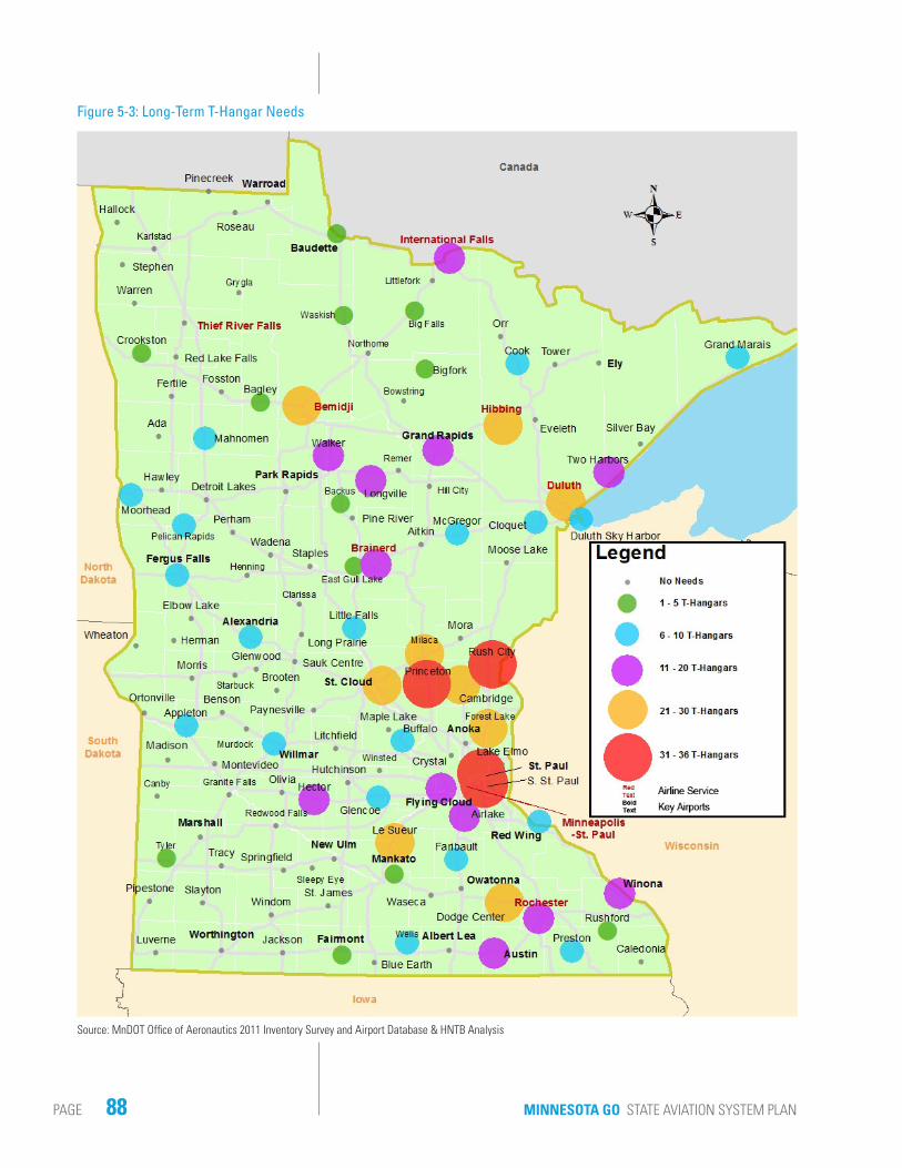
Over the next 20 years, as many as 69 airports may require additional hangars. Figure 5-2 and Figure 5-3
identify which airports in the system could benefit from additional aircraft storage space. Appendix E: Airport Facility Needs Sheets and Report Cards includes anticipated needs by airport.

87CHAPTER 5 AIRPORT FACILITY REQUIREMENTS PAGE
Figure 5-2: Long-Term Conventional Hangar Needs
Source: MnDOT Office of Aeronautics 2011 Inventory Survey and Airport Database & HNTB Analysis
88 MINNESOTA GO STATE AVIATION SYSTEM PLANPAGE
Figure 5-3: Long-Term T-Hangar Needs
Source: MnDOT Office of Aeronautics 2011 Inventory Survey and Airport Database & HNTB Analysis

89CHAPTER 5 AIRPORT FACILITY REQUIREMENTS PAGE
Aprons
An apron provides aircraft parking for both based and transient (visiting) aircraft at airports. Based aircraft apron area is generally utilized by aircraft which are not stored in hangars. The minimum system objective is to have only five percent of based SEP and MEP utilizing the apron. Transient aircraft apron area is used by non-based aircraft. The minimum system objective is to have apron space available for all transient aircraft during the peak hour itinerant operations. For the purposes of this Plan, the peak hour itinerant operations occur on the average day of the peak month (ADPM) for each airport.
Although peak operations vary from airport to airport, it is assumed that 20 percent of an airport’s total annual operations occur during the peak month. Peak hour operations were assumed to be 15 percent of the airport’s average daily operations in the peak month.
Another component necessary in determining apron area facility requirements is accounting for varying aircraft sizes. Table 5-7 shows the amount of apron area assumed for each aircraft category. These pavement areas include both the tie-down (parking position) area as well as the space necessary for maneuvering and taxiing the aircraft to a tie-down. The aircraft apron system needs are a factor of the minimum system objectives, the ADPM operations forecast, and the size requirements specified above.
Future apron area recommendations are to accommodate the expected traffic increase over the next twenty years. In total, nearly 1.7 million additional square yards of apron may be required by 2030. Only 60,000 square yards of the 1.7 million are expected to accommodate based aircraft. Figure 5-4 and Figure 5-5 identify which airports could benefit from additional apron area Appendix E: Airport Facility Needs Sheets and Report Cards shows the breakdown of anticipated needs by airport.
AIRCRAFT APRON SIZESingle Engine Piston (SEP) 360 S.Y.
Light Sport Aircraft (LSA) 360 S.Y.
Multi-Engine Piston (MEP) 360 S.Y.
Turboprop (TP) 600 S.Y.
Military (MIL) 600 S.Y.
Jet 700 S.Y.
Other 360 S.Y.
Table 5-7: Aircraft Apron Needs

90 MINNESOTA GO STATE AVIATION SYSTEM PLANPAGE
Figure 5-4: Long-Term Transient Apron Needs
Source: MnDOT Office of Aeronautics 2011 Inventory Survey and Airport Database & HNTB Analysis

91CHAPTER 5 AIRPORT FACILITY REQUIREMENTS PAGE
Figure 5-5: Long-Term Based Apron Needs
Source: MnDOT Office of Aeronautics 2011 Inventory Survey and Airport Database & HNTB Analysis

92 MINNESOTA GO STATE AVIATION SYSTEM PLANPAGE
Airline Terminals, General Aviation/Administration Buildings & Restrooms
This analysis considers the following three airport building facility types: airline terminals, general aviation (GA)/administration buildings, and restrooms.
AIRLINE TERMINALS
Airline terminals exist to accommodate airline passengers and contain equipment specific to this function, such as ticketing counters, Transportation Security Administration (TSA) screening, baggage processing and rental car facilities. The minimum system objective for airline terminals is to have one airline terminal at each Key Airport with scheduled airline service. The eight airports with scheduled airline service have terminals and therefore meet the minimum system objective.
GENERAL AVIATION/ADMINISTRATION BUILDINGS
General Aviation (GA) buildings may vary greatly in terms of size and use. While some airports have one large GA building which a fixed-base operator (FBO – a commercial business operating at an airport offering services such as fueling or parking) can utilize to deliver its services, others have only small administration buildings to conduct airport business. Some of the largest airports in the system have two or more administration buildings to accommodate each of these functions. These buildings typically contain offices, a flight planning area with a computer for weather reporting, restrooms and a waiting area. The minimum system objective for GA/administration buildings is to have one at each Key Airport without airline service and one at each Intermediate Airport. Only seven airports do not have either a GA or administration building.
RESTROOMS
There must be one restroom at each airport in the system, either as a stand-alone facility or as part of another building. There are seven Landing Strips which did not report having a restroom on airport.

93CHAPTER 5 AIRPORT FACILITY REQUIREMENTS PAGE
Table 5-8 below identifies the airports that do not meet the minimum system objectives for building facilities.
Automobile Parking
Automobile parking requirements for pilots of based aircraft, airport employees and visitors have been determined as part of this analysis. The minimum system objective identifies one parking space for each based aircraft at every airport plus increases at Key and Intermediate Airports for employees and visitors. Individual airport characteristics should be considered and will ultimately guide development. There are 76 airports which may benefit from auto parking projects over the next 20 years. Airports that do not meet the minimum system objectives for parking are identified in Appendix E: Airport Facility Needs Sheets and Report Cards.
AIRPORT IDENTIFIER AIRLINE TERMINAL
GA/ADMIN. BUILDING
STAND-ALONE
RESTROOM
Airlake LVN - X -
Anoka ANE - X -
Bagley 7Y4 - X -
Clarissa 8Y5 - - X
Crystal MIC - X -
East Gull Lake 9Y2 - - X
Elbow Lake Y63 - X -
Fertile D14 - - X
Flying Cloud FCM - X -
Glenwood GHW - X -
Grygla 3G2 - - X
Karlstad 23D - - X
Murdock 23Y - - X
Northome 43Y - - X
Table 5-8: Airline Terminal, GA/Administration Building & Stand-Alone Restroom Needs
Source: MnDOT Office of Aeronautics 2011 Inventory Survey and Airport Database & HNTB Analysis
94 MINNESOTA GO STATE AVIATION SYSTEM PLANPAGE
Perimeter Fencing
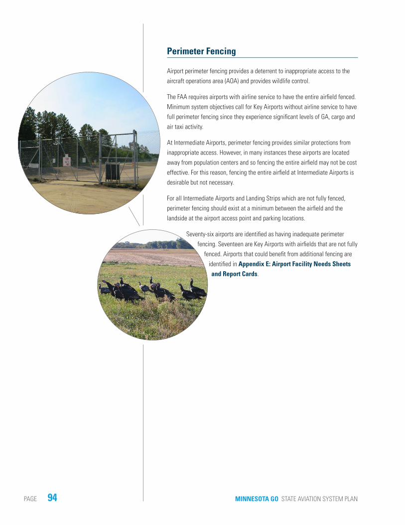
Airport perimeter fencing provides a deterrent to inappropriate access to the aircraft operations area (AOA) and provides wildlife control.
The FAA requires airports with airline service to have the entire airfield fenced. Minimum system objectives call for Key Airports without airline service to have full perimeter fencing since they experience significant levels of GA, cargo and air taxi activity.
At Intermediate Airports, perimeter fencing provides similar protections from inappropriate access. However, in many instances these airports are located away from population centers and so fencing the entire airfield may not be cost effective. For this reason, fencing the entire airfield at Intermediate Airports is desirable but not necessary.
For all Intermediate Airports and Landing Strips which are not fully fenced, perimeter fencing should exist at a minimum between the airfield and the landside at the airport access point and parking locations.
Seventy-six airports are identified as having inadequate perimeter fencing. Seventeen are Key Airports with airfields that are not fully
fenced. Airports that could benefit from additional fencing are identified in Appendix E: Airport Facility Needs Sheets and Report Cards.

95CHAPTER 5 AIRPORT FACILITY REQUIREMENTS PAGE
Fuel Facilities
On airport fuel facilities provide a high level of service to airport users. Two types of fuel may be available: 100 Low Lead (100LL) and Jet-A. The fuel facility minimum system objectives recommend 100LL at all airports with 24 hour service desirable at Intermediate and Key Airports. Additionally, Key Airports should provide Jet-A fuel. The 22 airports identified in Table 5-9 may benefit from additional fuel capacity by 2030.
AIRPORT IDENTIFIER FUELAirlake LVN X
Alexandria AXN X
Anoka ANE X
Baudette BDE X
Bemidji BJI X
Brainerd BRD X
Brooten 6D1 X
Cambridge CBG X
Ely ELO X
Fairmont FRM X
Glencoe GYL X
Hibbing HIB X
Holman Field STP X
Little Falls LXL X
Luverne LYV X
Milaca 18Y X
Minneapolis-St. Paul MSP X
Ortonville VVV X
Park Rapids PKD X
Preston FKA X
Princeton PNM X
Table 5-9: Fuel Capacity Needs
Source: MnDOT Office of Aeronautics 2011 Inventory Survey and Airport Database & HNTB Analysis

96 MINNESOTA GO STATE AVIATION SYSTEM PLANPAGE
This page intentionally left blank.