Embed Size (px)
Citation preview
Minnesota Department of Transportation _______________________________________________________________________________________ Transportation Building 395 John Ireland Blvd, M.S. 692 St Paul, MN 55155
Pre Letting Services Tel: 651-366-4615 Fax: 651-366-4680 February 15, 2010 TO: All Planholders of Record SUBJECT: State Project No. 2781-415 (T.H. 94=392) et al
Minnesota Project No. IM-STP 0943(562) Addendum No. 1
Date of Letting: FEBRUARY 25, 2011
A) General Decision MN100020 published 12/03/2010 is hereby deleted from the Proposal and the attached General Decision MN100020 published 02/04/2011 is substituted therefore. B) On Page No. 1 of the Schedule of Prices, the unit price on Line 0010 (CONSTRUCTION SURVEYING) will be considered to be zero dollars and zero cents ($00.00) regardless of any figure that may be entered thereon. This line will be deleted from the electronic bidding file. C) Section S-66 of the Special Provisions is hereby deleted, and the following is substituted therefore:
S-66 (2301) CONCRETE PAVEMENT (2011 version) (Rev. 2/16/2011)
Mn/DOT 2301 shall be deleted and replaced with the following: 2301.1 DESCRIPTION
This work consists of constructing portland cement concrete pavement on a prepared base.
The Department defines paving concrete to include concrete mainline, ramps, loops, integrant curb, shoulders, and curb and gutter placed adjacent to the concrete mainline with the same mixture used in the paving. Integrant curb is a curb constructed monolithically with the pavement.
For the purposes of concrete pavement, the Department defines a concrete plant as the following:
(1) A paving plant using dump or agitator trucks to haul concrete, or (2) A certified ready-mix plant using truck mixers to haul concrete.
For concrete pavement incentives and disincentives, the Department defines a concrete plant as the
following:
(1) A primary concrete plant providing the majority of the concrete to a paving project, and (2) A secondary concrete plant providing any minor work or fill-ins not provided by the
primary concrete plant.
Page 2 of 42 S.P. 2781-415 (T.H. 94=392) et al Addendum No. 1
Only one primary concrete plant per project is allowed unless otherwise approved by the Engineer. The Contractor may use a paving plant or a certified ready-mix plant as the primary concrete plant. 2301.2 MATERIALS A Concrete ..................................................................................................................................... 2461
A.1 Slipform Placement ................................................................................................... Mix No. 3A21
A.2 Fixed Form Placement .............................................................................................. Mix No. 3A41
B Coarse and Fine Aggregate Requirements
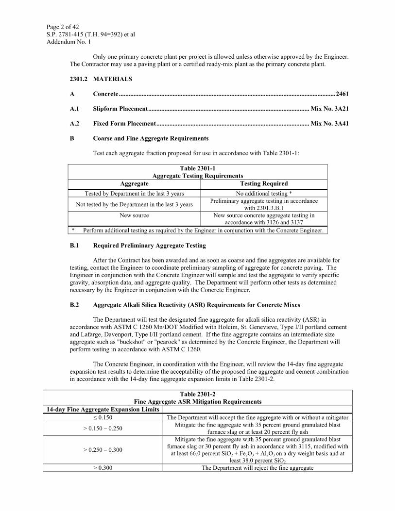
Test each aggregate fraction proposed for use in accordance with Table 2301-1:
Table 2301-1 Aggregate Testing Requirements
Aggregate Testing Required Tested by Department in the last 3 years No additional testing *
Not tested by the Department in the last 3 years Preliminary aggregate testing in accordance with 2301.3.B.1
New source New source concrete aggregate testing in accordance with 3126 and 3137
* Perform additional testing as required by the Engineer in conjunction with the Concrete Engineer. B.1 Required Preliminary Aggregate Testing
After the Contract has been awarded and as soon as coarse and fine aggregates are available for testing, contact the Engineer to coordinate preliminary sampling of aggregate for concrete paving. The Engineer in conjunction with the Concrete Engineer will sample and test the aggregate to verify specific gravity, absorption data, and aggregate quality. The Department will perform other tests as determined necessary by the Engineer in conjunction with the Concrete Engineer. B.2 Aggregate Alkali Silica Reactivity (ASR) Requirements for Concrete Mixes
The Department will test the designated fine aggregate for alkali silica reactivity (ASR) in accordance with ASTM C 1260 Mn/DOT Modified with Holcim, St. Genevieve, Type I/II portland cement and Lafarge, Davenport, Type I/II portland cement. If the fine aggregate contains an intermediate size aggregate such as "buckshot" or "pearock" as determined by the Concrete Engineer, the Department will perform testing in accordance with ASTM C 1260.
The Concrete Engineer, in coordination with the Engineer, will review the 14-day fine aggregate expansion test results to determine the acceptability of the proposed fine aggregate and cement combination in accordance with the 14-day fine aggregate expansion limits in Table 2301-2.
Table 2301-2 Fine Aggregate ASR Mitigation Requirements
14-day Fine Aggregate Expansion Limits ≤ 0.150 The Department will accept the fine aggregate with or without a mitigator
> 0.150 – 0.250 Mitigate the fine aggregate with 35 percent ground granulated blast furnace slag or at least 20 percent fly ash
> 0.250 – 0.300
Mitigate the fine aggregate with 35 percent ground granulated blast furnace slag or 30 percent fly ash in accordance with 3115, modified with
at least 66.0 percent SiO2 + Fe2O3 + Al2O3 on a dry weight basis and at least 38.0 percent SiO2
> 0.300 The Department will reject the fine aggregate
Page 3 of 42 S.P. 2781-415 (T.H. 94=392) et al Addendum No. 1
For fine aggregate and cement combinations previously tested by the Department, the Concrete
Engineer will use the previous test results to determine necessary mitigation. The Contractor may contact the Department to access the list of previously tested fine aggregate sources.
If the fine aggregate and cement combination were not previously tested, the Concrete Engineer will use the higher expansion result of the two fine aggregate and cement combinations to determine necessary mitigation.
Add "buckshot" or "pea rock as a separate aggregate in accordance with the quality requirements of 3137, except the Department will determine the shale content in accordance with AASHTO T 113 Mn/DOT Modified, "Lightweight Pieces in Aggregate" fine aggregate procedure. If this aggregate is from the same source as the ¾ in+ [19 mm+] or ¾ in– [19 mm–] aggregate, the Concrete Engineer will waive the requirements specified in 3137.2D3(c), "percent of the particles by weight (mass) of carbonate origin.". If this aggregate is from sources other than the ¾ in+ [19 mm+] or ¾ in– [19 mm–] aggregate, approval is at the discretion of the Concrete Engineer.
The Concrete Engineer may reject the fine aggregate if mortar bar specimens exhibit an indication of external or internal distress not represented by the expansion results. The Concrete Engineer will make the final acceptance of the aggregate. C Cementitious Materials
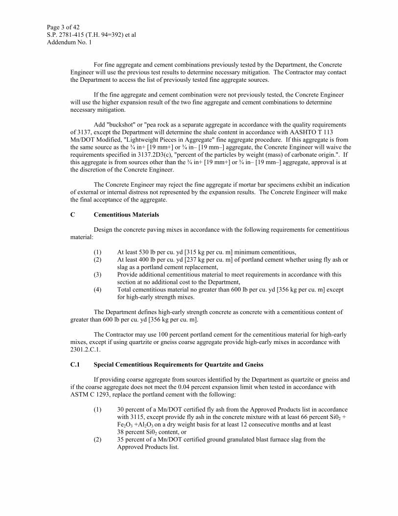
Design the concrete paving mixes in accordance with the following requirements for cementitious material:
(1) At least 530 lb per cu. yd [315 kg per cu. m] minimum cementitious, (2) At least 400 lb per cu. yd [237 kg per cu. m] of portland cement whether using fly ash or
slag as a portland cement replacement, (3) Provide additional cementitious material to meet requirements in accordance with this
section at no additional cost to the Department, (4) Total cementitious material no greater than 600 lb per cu. yd [356 kg per cu. m] except
for high-early strength mixes.
The Department defines high-early strength concrete as concrete with a cementitious content of greater than 600 lb per cu. yd [356 kg per cu. m].
The Contractor may use 100 percent portland cement for the cementitious material for high-early mixes, except if using quartzite or gneiss coarse aggregate provide high-early mixes in accordance with 2301.2.C.1. C.1 Special Cementitious Requirements for Quartzite and Gneiss
If providing coarse aggregate from sources identified by the Department as quartzite or gneiss and if the coarse aggregate does not meet the 0.04 percent expansion limit when tested in accordance with ASTM C 1293, replace the portland cement with the following:
(1) 30 percent of a Mn/DOT certified fly ash from the Approved Products list in accordance with 3115, except provide fly ash in the concrete mixture with at least 66 percent Si02 + Fe2O3 +Al2O3 on a dry weight basis for at least 12 consecutive months and at least 38 percent Si02 content, or
(2) 35 percent of a Mn/DOT certified ground granulated blast furnace slag from the Approved Products list.
Page 4 of 42 S.P. 2781-415 (T.H. 94=392) et al Addendum No. 1
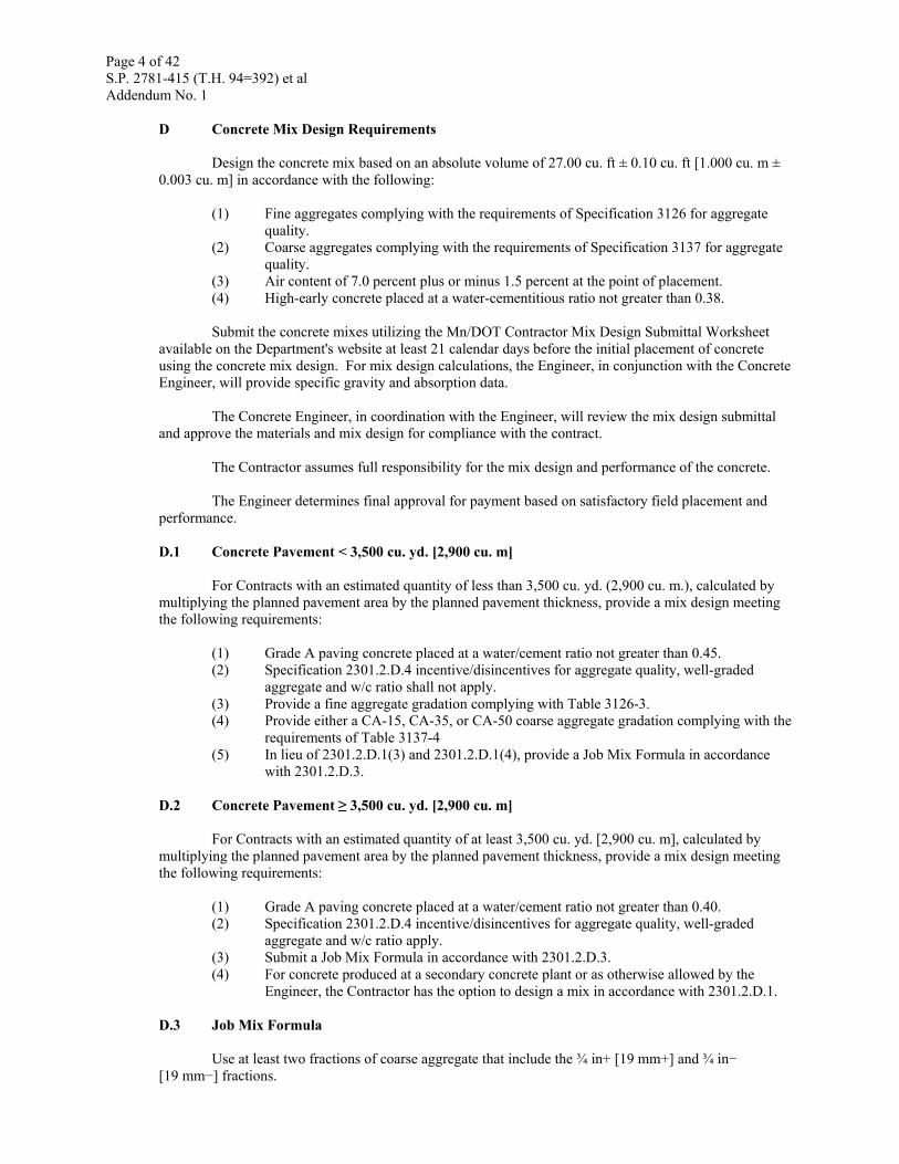
D Concrete Mix Design Requirements
Design the concrete mix based on an absolute volume of 27.00 cu. ft ± 0.10 cu. ft [1.000 cu. m ± 0.003 cu. m] in accordance with the following:
(1) Fine aggregates complying with the requirements of Specification 3126 for aggregate quality.
(2) Coarse aggregates complying with the requirements of Specification 3137 for aggregate quality.
(3) Air content of 7.0 percent plus or minus 1.5 percent at the point of placement. (4) High-early concrete placed at a water-cementitious ratio not greater than 0.38.
Submit the concrete mixes utilizing the Mn/DOT Contractor Mix Design Submittal Worksheet
available on the Department's website at least 21 calendar days before the initial placement of concrete using the concrete mix design. For mix design calculations, the Engineer, in conjunction with the Concrete Engineer, will provide specific gravity and absorption data.
The Concrete Engineer, in coordination with the Engineer, will review the mix design submittal and approve the materials and mix design for compliance with the contract.
The Contractor assumes full responsibility for the mix design and performance of the concrete.
The Engineer determines final approval for payment based on satisfactory field placement and performance. D.1 Concrete Pavement < 3,500 cu. yd. [2,900 cu. m]
For Contracts with an estimated quantity of less than 3,500 cu. yd. (2,900 cu. m.), calculated by multiplying the planned pavement area by the planned pavement thickness, provide a mix design meeting the following requirements:
(1) Grade A paving concrete placed at a water/cement ratio not greater than 0.45. (2) Specification 2301.2.D.4 incentive/disincentives for aggregate quality, well-graded
aggregate and w/c ratio shall not apply. (3) Provide a fine aggregate gradation complying with Table 3126-3. (4) Provide either a CA-15, CA-35, or CA-50 coarse aggregate gradation complying with the
requirements of Table 3137-4 (5) In lieu of 2301.2.D.1(3) and 2301.2.D.1(4), provide a Job Mix Formula in accordance
with 2301.2.D.3. D.2 Concrete Pavement ≥ 3,500 cu. yd. [2,900 cu. m]
For Contracts with an estimated quantity of at least 3,500 cu. yd. [2,900 cu. m], calculated by multiplying the planned pavement area by the planned pavement thickness, provide a mix design meeting the following requirements:
(1) Grade A paving concrete placed at a water/cement ratio not greater than 0.40. (2) Specification 2301.2.D.4 incentive/disincentives for aggregate quality, well-graded
aggregate and w/c ratio apply. (3) Submit a Job Mix Formula in accordance with 2301.2.D.3. (4) For concrete produced at a secondary concrete plant or as otherwise allowed by the
Engineer, the Contractor has the option to design a mix in accordance with 2301.2.D.1. D.3 Job Mix Formula
Use at least two fractions of coarse aggregate that include the ¾ in+ [19 mm+] and ¾ in− [19 mm−] fractions.
Page 5 of 42 S.P. 2781-415 (T.H. 94=392) et al Addendum No. 1
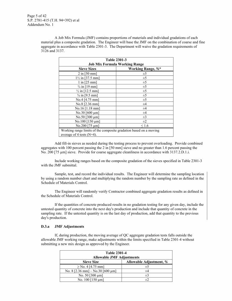
A Job Mix Formula (JMF) contains proportions of materials and individual gradations of each
material plus a composite gradation. The Engineer will base the JMF on the combination of coarse and fine aggregate in accordance with Table 2301-3. The Department will waive the gradation requirements of 3126 and 3137.
Table 2301-3 Job Mix Formula Working Range
Sieve Sizes Working Range, %* 2 in [50 mm] ±5
1½ in [37.5 mm] ±5 1 in [25 mm] ±5 ¾ in [19 mm] ±5
½ in [12.5 mm] ±5 ⅜ in [9.5 mm] ±5
No.4 [4.75 mm] ±5 No.8 [2.36 mm] ±4
No.16 [1.18 mm] ±4 No.30 [600 µm] ±4 No.50 [300 µm] ±3 No.100 [150 µm] ±2 No.200 [75 µm] ≤ 1.6
Working range limits of the composite gradation based on a moving average of 4 tests (N=4).
Add fill-in sieves as needed during the testing process to prevent overloading. Provide combined
aggregates with 100 percent passing the 2 in [50 mm] sieve and no greater than 1.6 percent passing the No. 200 [75 µm] sieve. Provide for coarse aggregate cleanliness in accordance with 3137.2.D.1.i.
Include working ranges based on the composite gradation of the sieves specified in Table 2301-3 with the JMF submittal.
Sample, test, and record the individual results. The Engineer will determine the sampling location
by using a random number chart and multiplying the random number by the sampling rate as defined in the Schedule of Materials Control.
The Engineer will randomly verify Contractor combined aggregate gradation results as defined in
the Schedule of Materials Control. If the quantities of concrete produced results in no gradation testing for any given day, include the
untested quantity of concrete into the next day's production and include that quantity of concrete in the sampling rate. If the untested quantity is on the last day of production, add that quantity to the previous day's production. D.3.a JMF Adjustments
If, during production, the moving average of QC aggregate gradation tests falls outside the allowable JMF working range, make adjustments within the limits specified in Table 2301-4 without submitting a new mix design as approved by the Engineer.
Table 2301-4 Allowable JMF Adjustments
Sieve Size Allowable Adjustment, % ≥ No. 4 [4.75 mm] ±5
No. 8 [2.36 mm] – No.30 [600 µm] ±4 No. 50 [300 µm] ±3
No. 100 [150 µm] ±2
Page 6 of 42 S.P. 2781-415 (T.H. 94=392) et al Addendum No. 1
The Contractor may continue paving after submitting a new JMF with working range and
aggregate volume adjustments to the Engineer. Submit all JMF adjustments on the Mn/DOT JMF Adjustments Worksheet available from the Department's website.
If the moving average of four tests falls outside of the adjusted allowable working range, stop production and provide a new mix design including JMF as directed by the Engineer in conjunction with the Concrete Engineer. D.4 Concrete Pavement Incentives and Disincentives
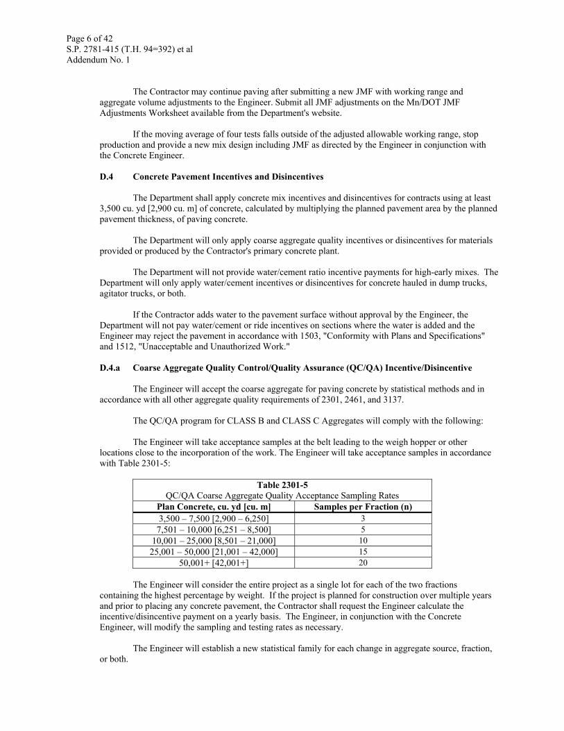
The Department shall apply concrete mix incentives and disincentives for contracts using at least
3,500 cu. yd [2,900 cu. m] of concrete, calculated by multiplying the planned pavement area by the planned pavement thickness, of paving concrete.
The Department will only apply coarse aggregate quality incentives or disincentives for materials provided or produced by the Contractor's primary concrete plant.
The Department will not provide water/cement ratio incentive payments for high-early mixes. The Department will only apply water/cement incentives or disincentives for concrete hauled in dump trucks, agitator trucks, or both.
If the Contractor adds water to the pavement surface without approval by the Engineer, the Department will not pay water/cement or ride incentives on sections where the water is added and the Engineer may reject the pavement in accordance with 1503, "Conformity with Plans and Specifications" and 1512, "Unacceptable and Unauthorized Work." D.4.a Coarse Aggregate Quality Control/Quality Assurance (QC/QA) Incentive/Disincentive
The Engineer will accept the coarse aggregate for paving concrete by statistical methods and in accordance with all other aggregate quality requirements of 2301, 2461, and 3137.
The QC/QA program for CLASS B and CLASS C Aggregates will comply with the following:
The Engineer will take acceptance samples at the belt leading to the weigh hopper or other locations close to the incorporation of the work. The Engineer will take acceptance samples in accordance with Table 2301-5:
Table 2301-5 QC/QA Coarse Aggregate Quality Acceptance Sampling Rates
Plan Concrete, cu. yd [cu. m] Samples per Fraction (n) 3,500 – 7,500 [2,900 – 6,250] 3
7,501 – 10,000 [6,251 – 8,500] 5 10,001 – 25,000 [8,501 – 21,000] 10
25,001 – 50,000 [21,001 – 42,000] 15 50,001+ [42,001+] 20
The Engineer will consider the entire project as a single lot for each of the two fractions
containing the highest percentage by weight. If the project is planned for construction over multiple years and prior to placing any concrete pavement, the Contractor shall request the Engineer calculate the incentive/disincentive payment on a yearly basis. The Engineer, in conjunction with the Concrete Engineer, will modify the sampling and testing rates as necessary.
The Engineer will establish a new statistical family for each change in aggregate source, fraction, or both.
Page 7 of 42 S.P. 2781-415 (T.H. 94=392) et al Addendum No. 1
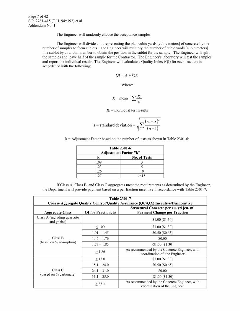
The Engineer will randomly choose the acceptance samples.
The Engineer will divide a lot representing the plan cubic yards [cubic meters] of concrete by the number of samples to form sublots. The Engineer will multiply the number of cubic yards [cubic meters] in a sublot by a random number to obtain the position in the sublot for the sample. The Engineer will split the samples and leave half of the sample for the Contractor. The Engineer's laboratory will test the samples and report the individual results. The Engineer will calculate a Quality Index (QI) for each fraction in accordance with the following:
)(skXQI +=
Where:
∑==nX imeanX
Xi = individual test results
( )( )∑ −
−==
1deviation standards
2
nxxi
k = Adjustment Factor based on the number of tests as shown in Table 2301-6:
Table 2301-6
Adjustment Factor "k" k No. of Tests
1.09 3 1.23 5 1.26 10 1.27 ≥ 15
If Class A, Class B, and Class C aggregates meet the requirements as determined by the Engineer,
the Department will provide payment based on a per fraction incentive in accordance with Table 2301-7.
Table 2301-7 Coarse Aggregate Quality Control/Quality Assurance (QC/QA) Incentive/Disincentive
Aggregate Class QI for Fraction, % Structural Concrete per cu. yd [cu. m]
Payment Change per Fraction Class A (including quartzite
and gneiss) — $1.00 [$1.30]
Class B (based on % absorption)
<1.00 $1.00 [$1.30] 1.01 – 1.45 $0.50 [$0.65] 1.46 – 1.76 $0.00 1.77 – 1.85 -$1.00 [$1.30]
> 1.86 As recommended by the Concrete Engineer, with coordination of the Engineer
Class C (based on % carbonate)
< 15.0 $1.00 [$1.30] 15.1 – 24.0 $0.50 [$0.65] 24.1 – 31.0 $0.00 31.1 – 35.0 -$1.00 [$1.30]
> 35.1 As recommended by the Concrete Engineer, with coordination of the Engineer
Page 8 of 42 S.P. 2781-415 (T.H. 94=392) et al Addendum No. 1
The Department will not pay incentives or disincentives for Class R aggregates.
If the concrete mixture contains at least three fractions of coarse aggregate, the Engineer will
consider only the two containing the highest percentage by weight as eligible for incentive. The Contractor may combine at least two sub-fractions to form the ¾ in – [19 mm –] fraction for either the coarse or fine fraction of the coarse aggregate. Blend the sub-fractions by weight. The Engineer will base the maximum incentive for aggregate quality on the two largest fractions by weight.
The Department will pay for Concrete Aggregate Quality for all paving concrete, including water/cement ratio concrete, and high-early concrete provided by the Contractor's primary paving plant. D.4.b Water/Cement (w/c) Ratio
Provide and place concrete with a water/cement ratio not to exceed 0.40. Make any adjustments immediately when the water/cement ratio exceeds 0.40.
The Department will not make incentive payments for water/cement ratio on high-early mixes.
Do not add water to the surface of the concrete to aid in finishing without the approval of the Engineer. Supply sufficient trucks to ensure a steady forward progress of the paver.
The Department will determine the water/cement ratio for concrete hauled in dump or agitator trucks in accordance with the following: D.4.b(1) Water Content Determination
For a concrete paving batch plant, use an electronic meter approved by the Engineer to record the water, including temper water, added to the mix that is capable of printing the amount of total water on each batch ticket.
For a ready-mix plant, record the total water added to the mix, including temper water, on the computerized Certificate of Compliance.
The Engineer will determine the water content for calculating the water/cement ratio using the average water calculated from 10 batch tickets or Certificates of Compliances surrounding the randomly selected batch ticket sample (four previous tickets, ticket representing the random sample, and the five following tickets). D.4.b(2) Water Content Verification
The Engineer will use plastic concrete taken at the plant site to verify the water content in the mix as determined in accordance with 2301.2.D.4.b.(1), "Water Content Determination." The Contractor will sample the plastic concrete as directed by the Engineer.
The Engineer will verify the water content in the plastic concrete mixture using the test procedure specified in AASHTO T 318-02, "Standard Test Method for Water Content of Freshly Mixed Concrete Using Microwave Oven Drying." The Engineer will begin the test within 45 min after the water has contacted the cement. Provide the microwave oven and the ancillary equipment as required by the Engineer to perform this test. D.4.b(3) Cementitious Content Determination
The Engineer will determine the cementitious content for calculating the water/cement ratio using the average total cementitious calculated from 10 batch tickets or Certificates of Compliances surrounding the randomly selected batch ticket sample (four previous tickets, ticket representing the random sample, and the five following tickets).
Page 9 of 42 S.P. 2781-415 (T.H. 94=392) et al Addendum No. 1
D.4.b(4) W/C Ratio Incentive/Disincentive
The Engineer will base the statistical analysis of acceptance for water/cement ratio in accordance with 2301.3.D.4.b(1) and 2301.3.D.4.b(3).
The Engineer will randomly choose acceptance samples. The Engineer will determine the sampling location by using a random number chart and multiplying the random number by the sampling rate as defined in the Schedule of Materials Control.
The Engineer will sample, test, and record the individual results.
If the quantities of concrete produced results in no Agency moisture testing for any given day, include the untested quantity of concrete into the next day's production and include that quantity of concrete in the sampling rate. If the untested quantity is on the last day of production, add that quantity to the previous day's production.
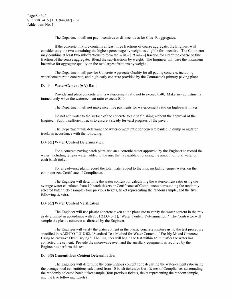
Do not place concrete mix not meeting the 0.40 water/cement ratio requirement in the work. The Engineer may accept material not meeting the contract requirements and the Department will pay for the work in accordance with Table 2301-8.
Table 2301-8 W/C Ratio Incentive/Disincentive
W/C Ratio Test ResultPayment incentive/disincentive per
cu. yard [cu. m] ≤ 0.37 +$3.00 [$3.90]
0.38 +$1.75 [$2.25]
0.39 $0.50 [$0.65] 0.40 $0.00 0.41 -$0.50 [$0.65] 0.42 -$1.75 [-$2.25]
0.43 -$3.00 [-$3.90] ≥ 0.44 Determined by the Concrete Engineer
The Contractor may remove and replace concrete represented by water/cement ratios greater than
0.40. For concrete left in place with water/cement ratios greater than 0.40, if the level of payment is not defined in the table, the Engineer in conjunction with the Concrete Engineer, will evaluate the material based on the adequacy of the material for the use intended. Remove and replace unsatisfactory concrete as determined by the Engineer at no additional cost to the Department. D.4.c Well-Graded Aggregate
The Engineer will use the Contractor's combined aggregate gradation test results, as verified by Department testing, to determine eligibility for the incentive.
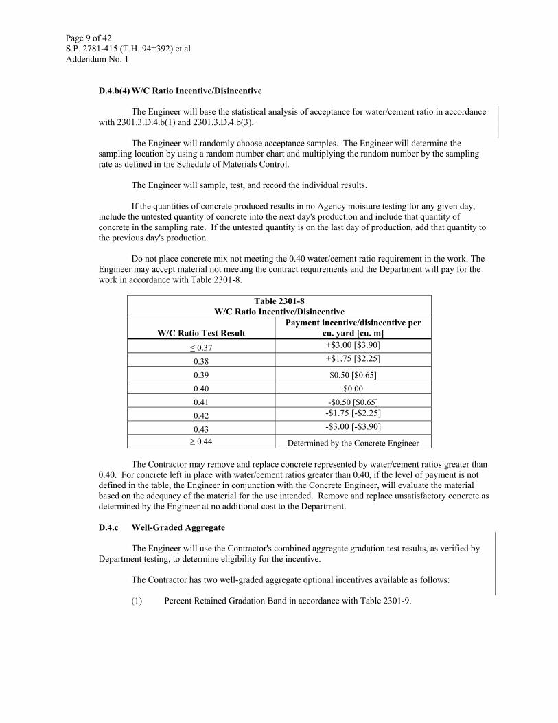
The Contractor has two well-graded aggregate optional incentives available as follows: (1) Percent Retained Gradation Band in accordance with Table 2301-9.
Page 10 of 42 S.P. 2781-415 (T.H. 94=392) et al Addendum No. 1
TABLE 2301-9 8-18 or 7-18 Percent Retained Gradation Band
Sieve Sizes 8-18 % Retained 7-18 % Retained 2 inch [50 mm] 0% 0%
1 ½ inch [37.5 mm] <9% <9% 1 inch [25 mm] 8% to 18% 7% to 18% ¾ inch [19 mm 8% to 18% 7% to 18%
½ inch [12.5 mm] 8% to 18% 7% to 18% 3/8 inch [9.5 mm] 8% to 18% 7% to 18%
#4 [4.75 mm] 8% to 18% 7% to 18% #8 [2.36 mm] 8% to 18% 7% to 18%
#16 [1.18 mm] 8% to 18% 7% to 18% #30 [600 µm] 8% to 18% 7% to 18% #50 [300 µm] < 13% < 13%
#100 [150 µm] <8% <7% #200 [75 µm] <8% <7%
(2) Gradation Zone II-A of the Coarseness Factor Chart in accordance with Table 2301-10.
TABLE 2301-10 Coarseness Factor Boundaries – Zone II-A
Coarseness Factor (CF) Workability Factor (WF) 52 34 - 38 68 32 - 36
The Coarseness Factor (CF) is defined as follows:
100 ×sieve mm] [2.36 No.8 above retained % Combinedsieve mm] [9.5in 3/8 above retained % Combined
=CF
The Workability Factor (WF) is defined as follows:
sieve mm] [2.36 8 No. passing % Combined = WF
The Engineer will use statistical analysis of the Contractor's combined aggregate gradation samples for well-graded aggregate on a lot basis representing one day's paving. The lot will represent the cumulative average of the sublot values on each sieve for the gradation band or the cumulative average of the sublot values of the coarseness factor and workability factor for the coarseness factor chart.
An optional incentive is available to the Contractor provided a concrete mixture is designed and
produced with a well-graded aggregate gradation that meets one of the following in accordance with Table 2301-11. The Contractor may achieve only one of the optional incentives for any single lot.
TABLE 2301-11
Well-Graded Aggregate Optional Incentive Gradation Options Payment incentive/disincentive per cu. yard [cu. m]
8-18 Retained $2.00 per cubic yard ($2.60 per m3) 7-18 Retained $0.50 per cubic yard ($0.65/m3)
Gradation Zone II-A $2.00 per cubic yard ($2.60 per m3) The Engineer will use the Contractor's combined aggregate gradation test results, as verified by
Department testing, to determine compliance. E Reinforcement Bars .................................................................................................................. 3301 F Dowel Bars ................................................................................................................................. 3302 G Concrete Joint Sealers
Page 11 of 42 S.P. 2781-415 (T.H. 94=392) et al Addendum No. 1
G.1 Preformed Type ....................................................................................................................... 3721 G.2 Hot-poured, Elastic Type ........................................................................................................ 3725 G.3 Silicone Type .............................................................................................................................. 3722 H Preformed Joint Filler .............................................................................................................. 3702 I Curing Materials I.1 Burlap Curing Blankets ............................................................................................................ 3751 I.2 Poly-Alpha Methylstyrene (AMS) Membrane Curing Compound ...................................... 3754 I.3 Linseed Oil Membrane Curing Compound ............................................................................ 3755 I.4 Plastic Curing Blankets ............................................................................................................ 3756 J Form Coating Material ............................................................................................................. 3902 2301.3 CONSTRUCTION REQUIREMENTS
Use "slipform" as the standard construction method for concrete paving, unless otherwise specified in the Contract or allowed by the Engineer. A.1 High-Early Strength Sections
For early use of the pavement as required by the Engineer, construct a section of pavement of high-early strength concrete in accordance with 2301.2.D, "Concrete Mix Design Requirements" at important road crossings, intersections, driveway entrances, or other locations as shown on the plans or directed by the Engineer. Take precautions to satisfactorily finish, cure, and protect high-early strength concrete pavements. A.2 Operation and Supervision
Notify the Engineer at least 24 h before placing concrete to allow for inspection. Do not place concrete until the Engineer approves preparations for concrete placement. If the Contractor fails to notify the Engineer at least 24 h before concrete placement, the Engineer may not allow concrete placement in accordance with 1503, "Conformity with Plans and Specifications" and 1512, "Unacceptable and Unauthorized Work."
Provide paving operations supervision in accordance with 1506, "Supervision by Contractor." Provide an organizational chart listing names and phone numbers of individuals and alternates responsible for mix design, quality control administration, and inspection to the Engineer. Post the organizational chart in the Contractor's on-site facility.
Provide a manufacturer's manual explaining the operation and adjustments of the major pieces of power operated equipment used. A.3 Plant Certification
Before beginning concrete production and in conjunction with the Engineer, perform a thorough on-site inspection of the concrete plant and complete Mn/DOT Form 2164, "Concrete Paving Plant Contact Report." Sign the report to certify compliance with the paving requirements and to certify review of the continual maintenance of the plant. Calibrate and correlate the testing equipment in accordance with 2461.3.D.
Page 12 of 42 S.P. 2781-415 (T.H. 94=392) et al Addendum No. 1
A.3.a Combination Plant Lab – Office Requirements
The Concrete Paving Contractor QC technicians and the Department QA technicians will equally share a combination plant lab – office during concrete paving.
For concrete paving projects in accordance with 2301.2.D.2, provide a separate combination plant lab – office in accordance with 1604, "Plant Inspection – Commercial Facility," and 2031.A, 2031.3.C, "Type D Service," except as modified by the following characteristics and requirements:
(1) Located at the plant site within 100 yd [91 m] from the batch plant or other location, as approved by the Engineer,
(2) Plant lab and plant office areas separated and isolated by a wall, (3) Total plant lab-office floor area, based on exterior dimensions, of at least 224 sq. ft
[21 sq. m], (4) Plant lab floor area, based on exterior dimensions, of at least 144 sq. ft [13.5 sq. m], (5) Plant office floor area, based on exterior dimensions, of at least 80 sq. ft [7.5 sq. m], (6) Plant lab furnished in accordance with 2031.3.B.2, "Field Laboratory Furnishings,"
except as modified by the following: (6.1) One sturdily built workbench or countertop at least 30 in × 144 in [0.75 m ×
3.65 m], (6.2) Shelf space above workbench or countertop or at other convenient locations,
totaling at least 8 linear ft [2.5 m] × 8 in [0.2 m], (6.3) Electronic scales of sufficient size to weigh the samples for all required
materials testing, and (6.4) At least four burners to perform required aggregate testing per the Schedule of
Materials Control. (7) Plant office furnished in accordance with 2031.3.B.1, "Field Office Furnishings" except
as modified by the following: (7.1) Two desks, one for the Department and one for the Contractor, with total
exterior dimensions of at least 30 in × 60 in [¾ m × 1.50 m], (7.2) At least six desk chairs, (7.3) File cabinets with at least two file drawers, one for the Department and one for
the Contractor, (7.4) A telephone capable of providing email, and (7.5) A printer with scanning and copying capabilities.
Do not begin concrete paving operations until the Engineer approves the combination plant lab–
office. The contract square yard [square meter] price for Concrete Pavement includes the cost of the plant lab-office. A.4 Sampling and Testing
Provide a Mn/DOT Certified Concrete Plant Level 2 Technician to oversee testing and plant operations and to remain on-site during concrete production or have cellular phone capability.
Provide technicians with certification at least meeting Mn/DOT Concrete Plant Level 1 to perform all of the duties in accordance with the Mn/DOT Concrete Manual. The Engineer will provide technicians with certification at least meeting Mn/DOT Concrete Plant Level 1 to perform all of the duties in accordance with the Mn/DOT Concrete Manual.
Performs testing in accordance with the Mn/DOT Concrete Manual and determines testing rates meeting the requirements of the Schedule of Materials Control. The Engineer performs testing in accordance with the Mn/DOT Concrete Manual and determines testing rates meeting the requirements of the Schedule of Materials Control.
Take samples randomly using ASTM D 3665, Section 5.
Page 13 of 42 S.P. 2781-415 (T.H. 94=392) et al Addendum No. 1
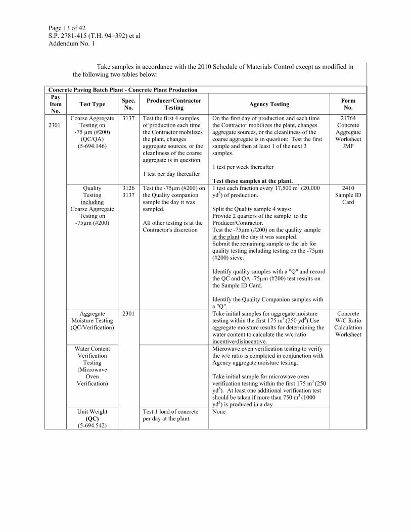
Take samples in accordance with the 2010 Schedule of Materials Control except as modified in
the following two tables below:
Concrete Paving Batch Plant - Concrete Plant ProductionPay Item No.
Test Type Spec. No.
Producer/Contractor Testing Agency Testing Form
No.
2301
Coarse Aggregate Testing on
-75 µm (#200) (QC/QA)
(5-694.146)
3137 Test the first 4 samples of production each time the Contractor mobilizes the plant, changes aggregate sources, or the cleanliness of the coarse aggregate is in question. 1 test per day thereafter
On the first day of production and each time the Contractor mobilizes the plant, changes aggregate sources, or the cleanliness of the coarse aggregate is in question: Test the first sample and then at least 1 of the next 3 samples. 1 test per week thereafter Test these samples at the plant.
21764 Concrete
Aggregate Worksheet
JMF
Quality Testing
including Coarse Aggregate
Testing on -75µm (#200)
3126 3137
Test the -75µm (#200) on the Quality companion sample the day it was sampled. All other testing is at the Contractor's discretion
1 test each fraction every 17,500 m3 (20,000 yd3) of production. Split the Quality sample 4 ways: Provide 2 quarters of the sample to the Producer/Contractor. Test the -75µm (#200) on the quality sample at the plant the day it was sampled. Submit the remaining sample to the lab for quality testing including testing on the -75µm (#200) sieve. Identify quality samples with a "Q" and record the QC and QA -75µm (#200) test results on the Sample ID Card. Identify the Quality Companion samples with a "Q".
2410 Sample ID
Card
Aggregate Moisture Testing (QC/Verification)
2301 Take initial samples for aggregate moisture testing within the first 175 m3 (250 yd3).Use aggregate moisture results for determining the water content to calculate the w/c ratio incentive/disincentive.
Concrete W/C Ratio Calculation Worksheet
Water Content
Verification Testing
(Microwave Oven
Verification)
Microwave oven verification testing to verify the w/c ratio is completed in conjunction with Agency aggregate moisture testing. Take initial sample for microwave oven verification testing within the first 175 m3 (250 yd3). At least one additional verification test should be taken if more than 750 m3 (1000 yd3) is produced in a day.
Unit Weight (QC)
(5-694.542)
Test 1 load of concrete per day at the plant.
None
Page 14 of 42 S.P. 2781-415 (T.H. 94=392) et al Addendum No. 1
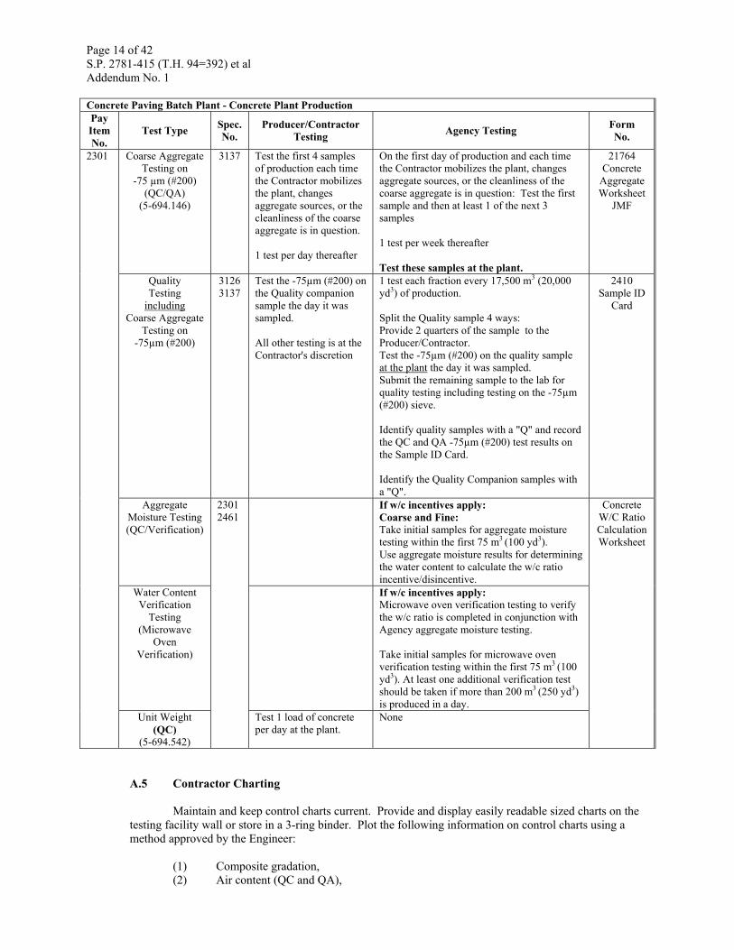
Concrete Paving Batch Plant - Concrete Plant ProductionPay Item No.
Test Type Spec. No.
Producer/Contractor Testing Agency Testing Form
No.
2301 Coarse Aggregate Testing on
-75 µm (#200) (QC/QA)
(5-694.146)
3137 Test the first 4 samples of production each time the Contractor mobilizes the plant, changes aggregate sources, or the cleanliness of the coarse aggregate is in question. 1 test per day thereafter
On the first day of production and each time the Contractor mobilizes the plant, changes aggregate sources, or the cleanliness of the coarse aggregate is in question: Test the first sample and then at least 1 of the next 3 samples 1 test per week thereafter Test these samples at the plant.
21764 Concrete
Aggregate Worksheet
JMF
Quality Testing
including Coarse Aggregate
Testing on -75µm (#200)
3126 3137
Test the -75µm (#200) on the Quality companion sample the day it was sampled. All other testing is at the Contractor's discretion
1 test each fraction every 17,500 m3 (20,000 yd3) of production. Split the Quality sample 4 ways: Provide 2 quarters of the sample to the Producer/Contractor. Test the -75µm (#200) on the quality sample at the plant the day it was sampled. Submit the remaining sample to the lab for quality testing including testing on the -75µm (#200) sieve. Identify quality samples with a "Q" and record the QC and QA -75µm (#200) test results on the Sample ID Card. Identify the Quality Companion samples with a "Q".
2410 Sample ID
Card
Aggregate Moisture Testing (QC/Verification)
2301 2461
If w/c incentives apply: Coarse and Fine: Take initial samples for aggregate moisture testing within the first 75 m3 (100 yd3). Use aggregate moisture results for determining the water content to calculate the w/c ratio incentive/disincentive.
Concrete W/C Ratio Calculation Worksheet
Water Content Verification
Testing (Microwave
Oven Verification)
If w/c incentives apply: Microwave oven verification testing to verify the w/c ratio is completed in conjunction with Agency aggregate moisture testing. Take initial samples for microwave oven verification testing within the first 75 m3 (100 yd3). At least one additional verification test should be taken if more than 200 m3 (250 yd3) is produced in a day.
Unit Weight (QC)
(5-694.542)
Test 1 load of concrete per day at the plant.
None
A.5 Contractor Charting
Maintain and keep control charts current. Provide and display easily readable sized charts on the testing facility wall or store in a 3-ring binder. Plot the following information on control charts using a method approved by the Engineer:
(1) Composite gradation, (2) Air content (QC and QA),
Page 15 of 42 S.P. 2781-415 (T.H. 94=392) et al Addendum No. 1
(3) Moisture content of aggregates, and (4) Water/cement ratio.
Also include the following information on the charts:
(1) Date, (2) Time, (3) Lot and sublot, (4) Admixture dosage adjustments, and (5) Other data necessary to facilitate control of the process.
Provide all reports, records, and diaries developed during the progress of construction activities to
the Engineer. Provide all batch tickets, test results, and control charts to the Engineer on a daily basis. The Engineer may suspend plant operations if the Contractor fails to provide daily test results. B Subgrade and Aggregate Base Preparations
Prepare the subgrade and aggregate base in accordance with 2112 and 2211 and the following:
Fine grade the subgrade to the required shape and grade as shown in the plans, allowing construction of the pavement to the specified thickness and cross section as shown in the plans. Use an approved fine grading machine mounted on crawler tracks.
Shape and maintain the shoulders to allow surface water to drain away from the pavement and off the shoulders. C Setting Forms
Provide forms meeting the following requirements and characteristics: (1) Steel, straight edge sides, (2) Depth equal to the specified pavement thickness, (3) Smooth and free of localized indentations and deformities, (4) Top face with deviations no greater than ⅛ in [3 mm] in any 10 ft [3 m] section, (5) Faces of straight forms with deviations no greater than ¼ in [13 mm] in any 10 ft [3 m]
section, (6) Side forms containing no bends or damaged sides, (7) Forms containing no damaged joint locks or pin pockets, and (8) Form lengths at least 10 ft [3 m] long with horizontal joint and base width equal to the
depth of the forms.
For pavements with radii no greater than 100 ft [30 m], use flexible or curved forms approved by the Engineer. Provide devices to securely set forms and withstand operation of the paving equipment without springing, settlement, or lateral displacement. Provide forms with joint locks to tightly join ends of abutting form sections together. Connect individual form sections using methods creating a continuous form.
Provide integrant curb forms conforming to the applicable requirements for paving forms and equip with clamps or other satisfactory means for support and alignment.
Set the forms to the proper alignment and grade as shown in the plans for a distance equal to at least 3 h ahead of concrete placement.
Compact the foundation before placing the forms in accordance with 2301.3.B. Ensure the forms have a firm and uniform bearing over the entire base area, are tightly joined and securely staked, and are clean and free of accumulations of hardened concrete. Coat the contact faces of the forms with a form coating material in accordance with 3902 before placing the concrete.
Page 16 of 42 S.P. 2781-415 (T.H. 94=392) et al Addendum No. 1
During a rain event, remove and reset the forms as necessary to allow drainage.
D Concrete Equipment and Paving Operations
Provide self-propelled spreading and finishing machines capable of consolidating and finishing the concrete, and producing a finished surface meeting the requirements specified. D.1 Slipform Construction
Place concrete using a slipform paver or combination of pavers designed to spread, consolidate, screed, and float-finish the freshly placed concrete with minimum hand finishing. Provide a slipform paver with a non-oscillating extrusion plate with an adjustable angle of entry.
Place the concrete pavement prior to placing curb and gutter. If the sequence of operations includes placing the curb and gutter prior to the concrete pavement, submit a jointing plan to the Engineer for approval prior to placing the curb and gutter.
Consolidate the full width and depth of concrete pavement placed by a single pass of a series of internal vibrators. Operate full-width vibrators from 3,600 VPM [60 Hz] to 7,000 VPM [117 Hz] in concrete and from 4,150 VPM [70 Hz] to 8,000 VPM [133 Hz] when checked in air. Deliver the vibrator impulses directly to the concrete and operate at an intensity to consolidate the concrete uniformly throughout the entire depth and width of the concrete. The Contractor may increase the vibrator frequency as approved by the Engineer. Perform additional testing as required by the Engineer at no additional cost to the Department. If the vibrator fails, suspend operations and remove unconsolidated concrete.
Regulate the rate of progress of the vibratory equipment and the duration of the application to fully, but not excessively, vibrate the concrete. Suspend the operation of vibrators if the forward progress of the paver stops.
Attach vibrators to spreading or finishing equipment. Do not allow vibrators to come in contact with preset dowel basket assemblies, the grade, pavement reinforcement, or side forms. Do not allow the operation of vibrators to cause separation or segregation of the mix ingredients, including the downward displacement of large aggregate or the accumulation of laitance on the concrete surface. The Contractor may reduce the vibration frequency within the specified range if reducing the forward motion of the paver to avoid segregation of the concrete mix. Connect the power to all vibrators so that they cease when the machine motion is stopped. Stop paving operations if a vibrator fails to operate within the specified range.
Provide an electronic monitoring device meeting the following characteristics and requirements to display the operating frequency of each individual internal vibrator for concrete pavement placed by the slipform method:
(1) Contains a readout display near the operator's controls; visible to the paver operator and to the Engineer,
(2) Operates continuously as the paving machine operates, (3) Displays all the vibrator frequencies with manual and automatic sequencing for each of
the individual vibrators, and (4) Records the following at least every 25 ft [7.62 m] of paving or at least every 5 min of
time: (4.1) Clock time, (4.2) Station location, (4.3) Paver track speed, and (4.4) Operating frequency of individual vibrators.
Provide an electronic copy containing the record of data after the completion of the concrete
paving operation. Provide vibration data daily as directed by the Engineer.
Page 17 of 42 S.P. 2781-415 (T.H. 94=392) et al Addendum No. 1
The contract square yard [square meter] price for Concrete Pavement includes the cost of providing, installing, and monitoring vibrators and vibrator monitoring devices.
Operate the slipform paver with a continuous forward movement, and coordinate all operations of mixing, delivering, and spreading concrete to provide uniform progress with minimal stopping and starting of the paver.
Equip the paver with automatic grade control capable of maintaining the proper elevation as shown in the plans at both sides of the paver, by controlling the elevation of one side and controlling the crown, or by controlling the elevation of each side independently. Achieve the grade reference by means of an erected string line.
Tightly stretch a wire or string line set parallel to the established grade for the pavement surface to achieve the grade reference. Set the control reference and support the line at intervals to maintain the established grade and alignment. D.2 Fixed Form Construction
Place concrete using one or more machines to spread, screed and consolidate between previously set side forms. Accomplish vibration of these areas using hand held or machine mounted internal vibrators.
If not using an electronic monitoring device, use a tachometer or similar device to demonstrate to the Engineer that the paving equipment vibration meets the requirements in this section.
Use hand held vibrators to consolidate concrete adjacent to side forms and fixed structures. Operate the hand held vibrators at a speed of at least 3,600 VPM [60 Hz]. Do not allow the vibrator head to contact the joints, load transfer devices, reinforcement, grade, or side forms. If the vibrator fails, suspend operations and remove unconsolidated concrete.
Continue vibration to achieve adequate consolidation, without segregation, for the full depth and width of the area placed.
Furnish an adequate number and capacity of machines to perform the work at a rate equal to the concrete delivery rate.
Strike-off concrete with a clary screed unless otherwise allowed by the Engineer. Finish small or irregular areas that are inaccessible to finishing equipment using other methods as approved by the Engineer.
Discontinue any operation that causes displacement of the side forms from the line or grade or causes undue delay, as determined by the Engineer, due to mechanical difficulties. E Batching and Mixing
Batch and mix the concrete in accordance with 2461 and the following: E.1 Batching Requirements
Perform the initial spot check of the measuring equipment in accordance with the Mn/DOT Concrete Manual for accuracy and sensitivity before starting production operations. Provide a copy of the inspection certificate to the Engineer.
Provide to the Engineer a computerized batch ticket that includes the following:
(1) Date, (2) State project number (SP) or (SAP), (3) Time concrete was batched,
Page 18 of 42 S.P. 2781-415 (T.H. 94=392) et al Addendum No. 1
(4) Quantity of concrete in this load, (5) Running total of each type of concrete, each day for each project, (6) Mix number, (7) Labels identifying each material that correlates with the contractor mix design, including
cementitious and admixture abbreviations or Mn/DOT 5 digit pit numbers), (8) Target weight of materials, (9) Actual batched weights of materials, (10) Temper water, and (11) Total water weight.
Suspend batching and mixing operations if satisfactory finishing and curing of the pavement does
not occur as determined by the Engineer.. E.2 Cement Cutoff and Yield
Submit the cement records to the Engineer. Make positive cement cutoffs, except if providing cement proportioned in a certified ready-mix plant, and delivering the batch to the construction site in truck mixers, in accordance with the following:
(1) Perform individual cement cutoffs at the following intervals: (1.1) After using 500,000 lb [250 tonne] of cement, (1.2) Before using 2,000,000 lb [1,000 tonne] of cement, (1.3) Using at least every 3,000,000 lb [1,500 tonne] or once a week, whichever provides the
longer time interval between cutoffs. (2) If delivering bulk cement directly to the concrete batching plant in railroad cars or sealed
transport trucks, submit copies of the freight bills to the Engineer on the same day received from the transporting company.
(3) Advise the Engineer of the method and schedule of cement unloading. Do not unload cement until the Engineer approves the operation.
The Engineer will verify the following:
(1) Individual cutoffs do not show an underrun in cement usage greater than 1.5 percent of
the quantity specified, and (2) The final cutoff does not show an overall underrun greater than 1.0 percent. (3) If either one or both of these limitations are exceeded, the Engineer will not pay for the
concrete represented at the Contract unit bid prices.
The Engineer may reject defective concrete in accordance with 1503, "Conformity with Plans and Specifications" and 1512, "Unacceptable and Unauthorized Work," or the Department may pay for the defective concrete at an adjusted unit price at the same ratio to the contract unit price as the quantity of cement used to the quantity of cement required less the allowable underrun. If the cement exceeds the limitations for individual cutoff and final cutoff, the Department may apply the price adjustment to the cutoff value that produces the greatest monetary deduction. F Placing Concrete
Dump or discharge concrete without causing grade displacement or damage to the asphalt bond breaker. Repair damage to the grade or bond breaker layer as approved by the Engineer. Provide protection for turning concrete trucks.
Maintain the grade in a moist condition until placement of concrete.
Construct mainline pavement in a single layer of concrete. Place the concrete pavement in one complete pass of the paving machine to minimize the need for hand finishing.
Page 19 of 42 S.P. 2781-415 (T.H. 94=392) et al Addendum No. 1
Coordinate paving operations for mixing, delivering, spreading, and extruding the concrete to provide uniform progress of the paver. Use sufficient trucks to ensure a steady forward progress of the paver. If the forward movement of the paver stops for a period long enough to create a cold joint or honeycombing, construct a header joint in accordance with 2301.3.H.3.
Do not add water to the surface of the concrete to aid in finishing without the approval of the Engineer.
When placing concrete on asphalt or asphalt bond breakers comply with the following:
(1) Do not place concrete on an asphalt surface with an asphalt surface temperature greater than 120° F [50° C].
(2) Maintain the asphalt surface in a moist condition and at a surface temperature not greater than 120° F [50° C] before placing the concrete.
(3) The Engineer will allow the Contractor to apply water and/or a whitewash of hydrated lime and water to cool the asphalt surface or other methods allowed by the Engineer.
(4) Before placing concrete on a milled asphalt surface, clean the milled surface by sweeping, and patch as shown in the plans in accordance with 2231or as required by the Engineer.
When placing concrete adjacent to in-place concrete pavement, protect the following:
(1) All ends of transverse joints 3/16" or wider to the satisfaction of the Engineer. The
Engineer will allow sawing through the existing joint when sawing the newly placed concrete, and
(2) The in-place pavement to prevent damage.
Do not allow the edges of the pavement, including longitudinal joints, to deviate from the line shown on the plans by greater than ½ in [13 mm] at any point.
Set manhole and catch basin frames or rings to the required elevation during the paving operations. F.1 Consistency
For slipform concrete pavement placement, place the concrete with a slump value that optimizes placement, except ensure the concrete does not slough or slump and is adequately consolidated and meets all other requirements. Maintain the concrete at a uniform consistency. The Engineer will not allow an edge slump greater than ⅛ in [3 mm] or irregular edge alignment.
For fixed form placement, place the concrete with a slump no greater than the maximum allowable slump in accordance with 2461.3.G.6. F.2 Air Content
Maintain the air content of Type 3 paving concrete at the specified target of 7.0 percent ±1.5 percent of the measured volume of the plastic concrete in accordance 1503.
Make any adjustments immediately to maintain the desired air content.
Measure the air content after placement on the grade but before consolidation.
If using the slipform paving method, establish an air loss correction factor (ACF) to determine the air content after consolidation once per half day of paving. Apply the ACF to tests taken before consolidation to estimate the air content after consolidation. Place concrete with an air content of at least 5.0 percent after consolidation.
Page 20 of 42 S.P. 2781-415 (T.H. 94=392) et al Addendum No. 1
Take the following actions for the following air content test results with the ACF applied or a test taken after consolidation:
(1) A single test (QC or QA) from 5.0 percent to 5.5 percent, adjust the mix design to obtain an air content greater than 5.5 percent without stopping production,
(2) Two consecutive tests (QC or QA) from 5.0 percent to 5.5 percent, make immediate adjustments to obtain an air content greater than 5.5 percent or stop production. Test every truck until the air content test results meet the requirements. Test at least three additional trucks after obtaining the correct air content.
(3) Any test (QC or QA) less than 5.0 percent, make immediate adjustments to obtain an air content greater than 5.5 percent or stop production. Test every truck until the air content meets the requirements. Test at least three additional trucks to ensure the concrete remains within compliance. Perform additional testing on the hardened concrete as required by the Engineer in conjunction with the Concrete Engineer.
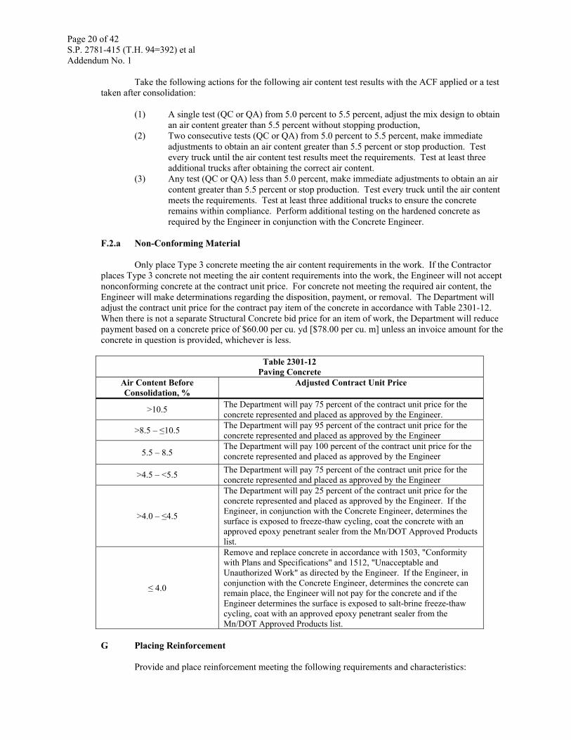
F.2.a Non-Conforming Material
Only place Type 3 concrete meeting the air content requirements in the work. If the Contractor places Type 3 concrete not meeting the air content requirements into the work, the Engineer will not accept nonconforming concrete at the contract unit price. For concrete not meeting the required air content, the Engineer will make determinations regarding the disposition, payment, or removal. The Department will adjust the contract unit price for the contract pay item of the concrete in accordance with Table 2301-12. When there is not a separate Structural Concrete bid price for an item of work, the Department will reduce payment based on a concrete price of $60.00 per cu. yd [$78.00 per cu. m] unless an invoice amount for the concrete in question is provided, whichever is less.
Table 2301-12 Paving Concrete
Air Content Before Consolidation, %
Adjusted Contract Unit Price
>10.5 The Department will pay 75 percent of the contract unit price for the concrete represented and placed as approved by the Engineer.
>8.5 – ≤10.5 The Department will pay 95 percent of the contract unit price for the concrete represented and placed as approved by the Engineer
5.5 – 8.5 The Department will pay 100 percent of the contract unit price for the concrete represented and placed as approved by the Engineer
>4.5 – <5.5 The Department will pay 75 percent of the contract unit price for the concrete represented and placed as approved by the Engineer
>4.0 – ≤4.5
The Department will pay 25 percent of the contract unit price for the concrete represented and placed as approved by the Engineer. If the Engineer, in conjunction with the Concrete Engineer, determines the surface is exposed to freeze-thaw cycling, coat the concrete with an approved epoxy penetrant sealer from the Mn/DOT Approved Products list.
≤ 4.0
Remove and replace concrete in accordance with 1503, "Conformity with Plans and Specifications" and 1512, "Unacceptable and Unauthorized Work" as directed by the Engineer. If the Engineer, in conjunction with the Concrete Engineer, determines the concrete can remain place, the Engineer will not pay for the concrete and if the Engineer determines the surface is exposed to salt-brine freeze-thaw cycling, coat with an approved epoxy penetrant sealer from the Mn/DOT Approved Products list.
G Placing Reinforcement
Provide and place reinforcement meeting the following requirements and characteristics:
Page 21 of 42 S.P. 2781-415 (T.H. 94=392) et al Addendum No. 1
(1) Provide epoxy coated reinforcement in accordance with 2472, (2) Provide and place reinforcement bars including keyway bars, tie bars, taper steel, and
stopper bars, (3) Place keyways as shown on the plans, (4) Provide and place supplemental pavement reinforcement as shown on the plans, (5) Provide and place reinforcement bars on chairs or by appropriate equipment for
depressing the bars to the specified location, and (6) For slipform paving, use a mechanical device attached to the spreader or paver to place
tie bar steel required for L1T joints as shown on the plans. Space and depress the tie bar steel to the desired depth and location as shown on the plans. Do not place tie bars over a dowel bar assembly.
H Joint Construction
Unless otherwise shown on the plans, construct all joints perpendicular to the grade. Place dowel bars parallel to the grade and parallel to the centerline of the pavement. H.1 Dowel Bar Placement
Provide dowel bar assemblies manufactured in single units for the lane widths as shown on the plans, unless otherwise approved by the Engineer. Do not use more than two assembled sections in any one joint for ramps, loops, and tapered sections.
Secure the dowel bar assemblies to prevent movement during concrete placement in accordance with Mn/DOT Standard Plate 1103 and the following:
(1) If placing dowel bar assemblies on asphalt or asphalt bond breaker layers, secure the assemblies with at least seven anchorage points. Place four of the anchorage points on the assembly side facing the front of the paver. Fasten the assemblies in accordance with the following: (1.1) Place pins or fasteners of sufficient length and shank diameter of at least
0.177 in [0.45 cm] to penetrate through the asphalt bond breaker layer and into the concrete at least 1 in [25 mm] or at least 2 in [50 mm] into the in-place asphalt layer,
(1.2) Before paving, demonstrate the fastening method to the Engineer for approval.
Within 1 h before covering with concrete, coat the dowel bars with a thin uniform coating of an approved form coating material in accordance with 3902 and listed on the Mn/DOT Approved Products List.
Before placing the concrete, mark the location on both sides of each transverse joint as approved by the Engineer. Transfer the markings to the fresh concrete immediately after completing the final finishing operations.
The Contractor may use a mechanical dowel bar inserter to place dowel bars in the pavement as approved by the Engineer, in conjunction with the Concrete Engineer. Immediately before inserting the dowels, coat the dowels with a thin uniform coating of an approved form coating material in accordance with 3902 and listed on the Mn/DOT Approved Products List. If using a dowel bar inserter, initially and on each production day, demonstrate to the Engineer that the inserted dowel bars in the completed concrete pavement are parallel to the surface and centerline slab and are located at mid depth of the slab thickness. H.2 Joint Establishment
Space contraction joints at the intervals shown on the plans, except shorten the spacing at the following to provide panel lengths at least 5 ft [1.5 m]:
(1) Adjacent to header joints,
Page 22 of 42 S.P. 2781-415 (T.H. 94=392) et al Addendum No. 1
(2) Reinforced panels, (3) Railroad grade crossings, and (4) Free ends of pavement.
Provide either wet-cut saws referred to as "conventional concrete saws" or lighter weight dry-cut
saws referred to as "early-entry concrete saws" capable of establishing joints sooner than the conventional saws.
Provide initial joint sawing as shown on the plans. Perform the initial sawing as soon as the the concrete will support the joint sawing operation without raveling and before random cracking occurs.
Immediately after completing the joint sawing, use water under nozzle pressure to remove the sawing residue from each joint and the pavement surface.
If widening is necessary, do not widen the joints to full width until the concrete is at least 24 h old or longer if the sawing causes raveling of the concrete.
Stake preformed joint filler material for expansion joints in place to maintain proper position as shown on the plans during concrete placement.
Extend transverse joints constructed in the pavement through the integrant curb. H.3 Constructing Headers
Construct construction headers, temporary headers, and permanent headers as shown on the plans.
The Engineer will not allow incorporating any concrete accumulated in the grout box of the paver into the pavement. Construct all headers such that the concrete contained in the grout box is removed from the project. Use any approved construction header method as shown in the Standard Details.
Use internal vibration to consolidate the concrete along header joints before final finishing. I Surface Finishing
Use a ⅜ in [10 mm] radius edging tool to finish edges of the pavement.
After consolidating, screeding, and floating the concrete, give the pavement surface a final finish texture in accordance with 2301.3.I.1, "Pavement Texture" unless 2301.3.I.2, "Pavement Tining" is required in the Contract. I.1 Pavement Texture
Test the adequacy of the pavement skid resistance meeting the requirements of ASTM E 965-87, "Test Method for Measuring Surface Macrotexture Depth Using a Sand Volumetric Technique." Provide a texture depth of at least 1/25 in [1.00 mm].
The Department defines a lot as pavement of a single lane. Establish a separate lot for each lane on the project.
The Department defines a sublot as the rate at which an individual measurement is taken over a given length. The Department considers a sublot as one lane wide, measured in accordance with the following:
(1) From the pavement edge to the adjacent longitudinal joint, (2) From one longitudinal joint to the next, or (3) In the absence of a longitudinal joint, between pavement edges. (4) Each ramp and loop 18' (5.5 m) wide or less is considered a single lane.
Page 23 of 42 S.P. 2781-415 (T.H. 94=392) et al Addendum No. 1
The Engineer will break lots into sublots representing 1,000 linear ft [300 m] of pavement. Test
the pavement surface at a point located transversely in the outside wheel path as determined by the Engineer. Test adjoining driving lanes at the same location. The Engineer will determine the locations using a random number multiplied by length of the sublot. If the project or individual lane results in less than three sublots, the Engineer will divide the project or individual lane lot into three sublots of equal length.
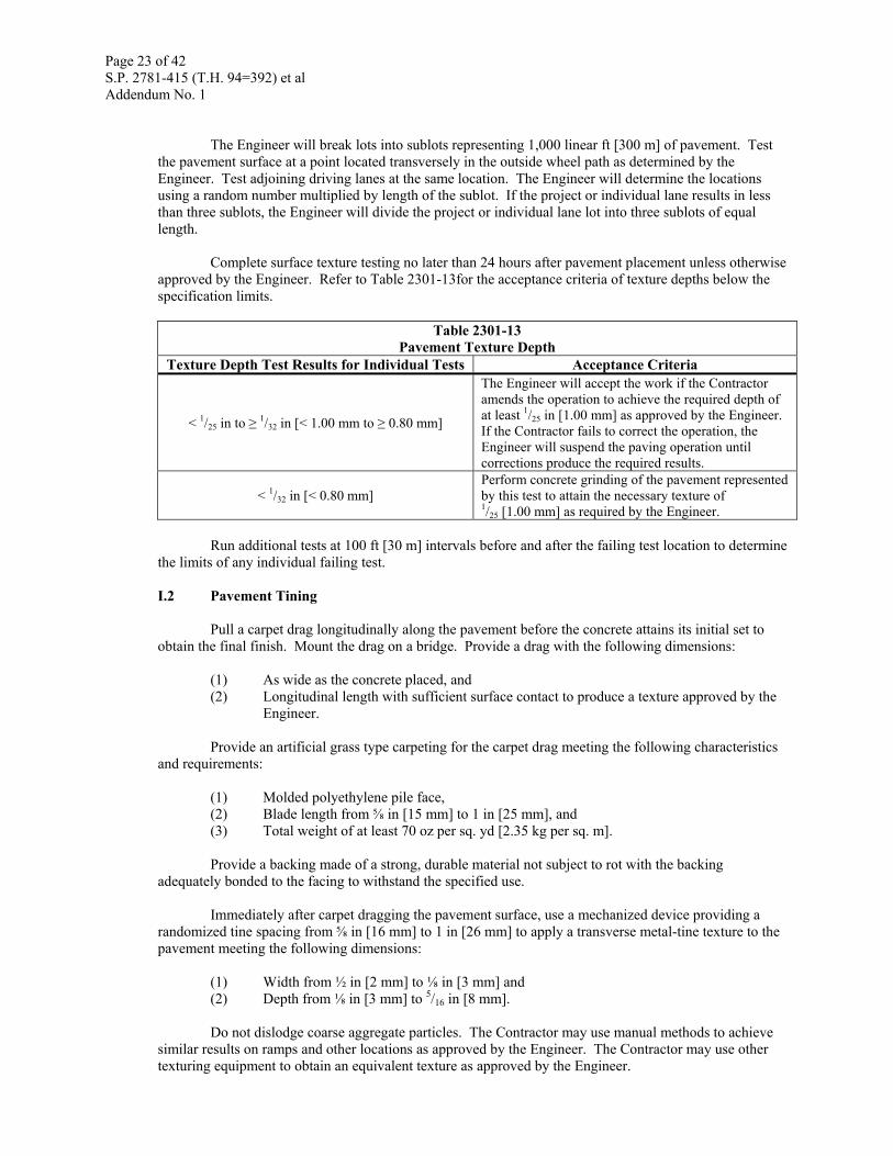
Complete surface texture testing no later than 24 hours after pavement placement unless otherwise approved by the Engineer. Refer to Table 2301-13for the acceptance criteria of texture depths below the specification limits.
Table 2301-13 Pavement Texture Depth
Texture Depth Test Results for Individual Tests Acceptance Criteria
< 1/25 in to ≥ 1/32 in [< 1.00 mm to ≥ 0.80 mm]
The Engineer will accept the work if the Contractor amends the operation to achieve the required depth of at least 1/25 in [1.00 mm] as approved by the Engineer. If the Contractor fails to correct the operation, the Engineer will suspend the paving operation until corrections produce the required results.
< 1/32 in [< 0.80 mm] Perform concrete grinding of the pavement represented by this test to attain the necessary texture of 1/25 [1.00 mm] as required by the Engineer.
Run additional tests at 100 ft [30 m] intervals before and after the failing test location to determine
the limits of any individual failing test. I.2 Pavement Tining
Pull a carpet drag longitudinally along the pavement before the concrete attains its initial set to obtain the final finish. Mount the drag on a bridge. Provide a drag with the following dimensions:
(1) As wide as the concrete placed, and (2) Longitudinal length with sufficient surface contact to produce a texture approved by the
Engineer.
Provide an artificial grass type carpeting for the carpet drag meeting the following characteristics and requirements:
(1) Molded polyethylene pile face, (2) Blade length from ⅝ in [15 mm] to 1 in [25 mm], and (3) Total weight of at least 70 oz per sq. yd [2.35 kg per sq. m].
Provide a backing made of a strong, durable material not subject to rot with the backing
adequately bonded to the facing to withstand the specified use.
Immediately after carpet dragging the pavement surface, use a mechanized device providing a randomized tine spacing from ⅝ in [16 mm] to 1 in [26 mm] to apply a transverse metal-tine texture to the pavement meeting the following dimensions:
(1) Width from ½ in [2 mm] to ⅛ in [3 mm] and (2) Depth from ⅛ in [3 mm] to 5/16 in [8 mm].
Do not dislodge coarse aggregate particles. The Contractor may use manual methods to achieve
similar results on ramps and other locations as approved by the Engineer. The Contractor may use other texturing equipment to obtain an equivalent texture as approved by the Engineer.
Page 24 of 42 S.P. 2781-415 (T.H. 94=392) et al Addendum No. 1
The Engineer will not require metal-tine texturing on subsidiary paving areas such as cross-overs
and parking lanes exempted by the Engineer, or on areas with speed limits no greater than 35 mph [55 km/h] as specifically exempted by the contract or the Engineer. J Concrete Curing and Protection
After completing final finishing operations, cure all exposed concrete surfaces for at least 72 hours. Extend the minimum curing period to 96 hours when using fly ash or cementitious substitutions as defined in 2461.A.6. Use one of the following curing methods:
(1) Place the membrane curing compound conforming to 3754 or 3755 within 30 minutes of
concrete placement or once the bleed water has dissipated unless otherwise directed by the Engineer in accordance with 2301.3.J.1.a. Place the membrane curing compound on the edges within 30 minutes after permanent removal of the forms or curing blankets unless otherwise specified in the Contract.
(2) Place plastic curing blankets or completely saturated burlap curing blankets as soon as practical without marring the surface in accordance with 2301.3.J.1.b.
Whenever weather conditions are such as to cause unusual or adverse placing and finishing conditions or equipment failures occur, expedite the application of a curing method or temporarily suspend the mixing and placing operations, as the conditions require.
If necessary to remove the coverings to saw joints or perform other required work, and if the Engineer approves, remove the covering for the minimum time required to complete that work.
Failure to comply with the above provisions will result in the Engineer, in conjunction with the
Concrete Engineer, applying a monetary deduction in accordance with 1503. When there is not a separate Structural Concrete bid price for an item of work, the Department will apply a monetary deduction of $30.00 per cu. yd [$39.00 per cu. m] or 50% of the Contractor-provided invoice amount for the concrete in question, whichever is less.
J.1 Curing Methods J.1.a Membrane Curing Method
Before application, agitate the curing compound as received in the shipping container to obtain a homogenous mixture. Protect membrane curing compounds from freezing before application. Handle and apply the membrane curing compound in accordance with the manufacturer's recommendations.
Apply the curing compound in accordance with the following:
(1) At a rate of 1 gal per 150 sq. ft (1 L per 4 m2) of surface curing area. (2) Apply curing compound homogeneously to provide a uniform, solid, white opaque
coverage on all exposed concrete surfaces (equal to a white sheet of typing paper). If using a Department - approved curing compound with a non-white base color, apply the compound to provide a uniform, solid, opaque consistency meeting the intent of the requirement in this section.
(3) If the curing compound is damaged during the curing period, immediately repair the damaged area by re-spraying.
(4) If the Engineer determines that the initial or corrective spraying result in unsatisfactory curing, the Engineer may require the Contractor to use the blanket curing method at no additional cost to the Department.
Use the fully-automatic, self-propelled mechanical power sprayer approved by the Engineer to
apply the curing compound in accordance with the following:
Page 25 of 42 S.P. 2781-415 (T.H. 94=392) et al Addendum No. 1
(1) Operate the equipment to direct the curing compound to the surface from two different lateral directions,
(2) Do not allow the sprayer to ride on the pavement surface, (3) Ensure the sprayer covers the entire lane width and atomizes the curing compound, and (4) If puddling, dripping, or non-uniform application occurs, suspend the operation to
perform corrections as approved by the Engineer. Use a fully-automatic, self-propelled mechanical power sprayer equipped with the following to
apply curing compound as approved by the Engineer: (1) A re-circulating bypass system that provides for continuous agitation of the reservoir
material, (2) Separate filters for the hose and nozzle, (3) Check valve nozzles, (4) Multiple or adjustable nozzle system that provides for variable spray patterns, (5) A shield to control loss of material by wind action, and (6) A spray bar drive system that operates independently of the wheels or track drive system. The Engineer will permit an airless spraying machine for applying the curing compound on
pavements that are 10 feet (3 m) or less in width and irregular shaped surfaces that comply with the following:
(1) A re-circulating bypass system that provides for continuous agitation of the reservoir
material, (2) Separate filters for the hose and nozzle, and (3) Multiple or adjustable nozzle system that provides for variable spray patterns.
J.1.b Blanket Curing Method After completion of the finishing operations and without marring the concrete, cover the concrete with curing blankets. Install in a manner that envelops the exposed concrete and prevents loss of water vapor. After the concrete has cured, apply membrane curing compound to the concrete surfaces that will remain exposed in the completed work. J.2 Protection Against Rain
Protect the concrete from damage due to rain. Have available, near the site of the work, materials for protection of the edges and surface of concrete. Should any damage result, the Engineer will suspend operations until corrective action is taken and may subject the rain-damaged concrete to 1503 and 1512.
J.3 Protection Against Cold Weather
If the national weather service forecast for the construction area predicts air temperatures of 34 °F [1 °C] or less within the next 24 h and the Contractor wishes to place concrete, submit a cold weather protection plan.
Protect the concrete from damage including freezing due to cold weather. Should any damage
result, the Engineer will suspend operations until corrective action is taken and may subject the damaged concrete to 1503 and 1512.
J.3.a Cold Weather Protection Plan
Submit a proposed time schedule and Plans for cold weather protection of concrete in writing to the Engineer for acceptance that provides provisions for adequately protecting the concrete during placement and curing. Do not place concrete until the Engineer accepts the Contractor's cold weather protection plans.
Page 26 of 42 S.P. 2781-415 (T.H. 94=392) et al Addendum No. 1
J.4 Vibratory and Backfilling Protection
Protect newly placed concrete from damage by adjacent vibratory or backfilling operations for a minimum of 24 hours. Resume vibratory and backfilling operations after the concrete has reached a minimum compressive strength of 2000 psi or a flexural strength of 250 psi. Cast concrete control specimens in accordance with 2461.3.G.5. The Engineer will test the control specimens. If the Engineer discovers evidence of damaged concrete, the Engineer will suspend work until the Contractor corrects the work. The Engineer may reject damaged concrete in accordance with 1503, "Conformity with Plans and Specifications" and 1512, "Unacceptable and Unauthorized Work."
The Contractor may use hand operated concrete consolidation equipment, walk behind vibratory plate compactors, rollers in "static" mode, and fine grading machines 24 h after placing the concrete, and other equipment as approved by the Engineer in conjunction with the Concrete Engineer. K Removal of Forms
Do not remove side forms of pavement and back forms on integrant curb earlier than 12 h after placing the concrete, unless otherwise approved by the Engineer. Remove forms without exerting shock or strain, including temperature variations, on the pavement or curb. Cure concrete in accordance with 2301.3.J. L Joint Sealing
Provide an approved sealant in accordance with 3725 and listed on the Mn/DOT Approved Products List, unless the type of sealant for contraction joints is otherwise specified in the contract.
Do not seal joints with silicone in accordance with 3722 if the concrete mixture contains Class B coarse aggregate as defined in 3137.
Perform joint sealing as shown on the plans and in accordance with the following:
(1) Seal joints after the Engineer inspects and approves the joints, (2) Perform joint sealing on surface dry concrete after cleaning the joints of debris, dirt, dust,
and other foreign matter, including accumulations of concrete, (3) Lightly sandblast the joint walls before final compressed air cleaning, (4) Immediately before sealing the joints, clean the joints with a jet of compressed air under
pressure of at least 85 psi [580 kPa], (5) Seal transverse integrant curb joints with the same joint sealer used to seal the pavement
joints, (6) Seal joints in accordance with the tolerances shown on the plans, (7) Provide backer rod material compatible with the sealer as shown on the plans, and (8) Remove and replace sealer at joints filled above the permissible level as shown on the
plans at no additional cost to the Department.
Handle and place joint sealer material as recommended by the manufacturer and in accordance with the following requirements: L.1 Hot Poured Sealers
Heat hot poured sealers in a double-boiler type kettle or melter. Fill the space between inner and outer shells with oil or other material as allowed by the Manufacturer. Provide heating equipment with automatic temperature control, mechanical agitation, and recirculating pump. Use heating equipment as recommended by the manufacturer of the sealer material. Do not melt quantities of sealer material greater than the quantity used within the same day. After heating the sealer material to the application temperature, maintain the material temperature until placement. Place the sealer material within 4 h after the initial heating to the application temperature.
Page 27 of 42 S.P. 2781-415 (T.H. 94=392) et al Addendum No. 1
Apply sealant to the pavement at ambient pavement temperatures greater than 39° F [4° C]. L.2 Silicone Sealers
Install silicone sealers as recommended by the manufacturer. L.3 Preformed Sealers
Provide preformed seals in one continuous length for each joint, except the Contractor may use butt splices in transverse joints at longitudinal joints.
Do not stretch the preformed sealer material in the installation process by greater than 5 percent of the joint length. M Workmanship and Quality M.1 Defective Pavement
The Department will pay for concrete pavement meeting the requirements and tolerances in accordance with this section at the contract unit price. Pavement that fails to meet the minimum requirements when tested in the prescribed manner is considered defective. The Department may reject or adjust the payment for defective concrete pavement in accordance with 1503, "Conformity with Plans and Specifications" and 1512, "Unacceptable and Unauthorized Work."
The Engineer will determine the limits of each individual defective pavement area. If adjusting the price for defective payment, the Engineer will measure the area to the nearest whole square yard [square meter], except the Engineer will consider areas less than 1 sq. yd [1 sq. m] as 1 sq. yd [1 sq. m]. The Engineer will determine the condition of each individual defective area of pavement based on the calculation of greatest deficiency within that area. M.2 Random or Uncontrolled Cracking
Repair or replace pavement with random or uncontrolled cracks as directed by the Engineer. If repairing the pavement as directed by the Engineer, use a dowel bar load transfer technique in accordance with the Department's Concrete Pavement Rehabilitation Details on the Department's website. Submit the intended repair technique to the Engineer for approval. Perform pavement repairs at no additional cost to the Department. If the repair fails, replace the pavement at no additional cost to the Department. The Engineer will accept repairs in accordance with 1516, "Acceptance of Work." M.3 Pavement Smoothness – IRI (International Roughness Index)
Provide concrete pavement smoothness in accordance with 2399. N Thickness Requirements
Provide pavement with a finished pavement thickness as shown on the plans or as modified, in writing, by the Engineer. Modifications by the Engineer are still considered the plan thickness. N.1 QC/QA Procedure
Construct pavement to the thickness shown on the plans. On each project and on each roadbed of a divided highway, evaluate pavement thickness in accordance with the following:
(1) Contractor Quality Control Probing (QCP), (2) Probe Verification Core (PVC), and (3) Quality Assurance Core (QAC).
Page 28 of 42 S.P. 2781-415 (T.H. 94=392) et al Addendum No. 1
The Department defines plan thickness lot (PTL) as concrete pavement of the same thickness added together lineally. Establish a separate PTL for each concrete plan thickness on the project.
The Department defines a sublot as the rate at which an individual measurement is taken over a given length. The Department considers a sublot as one lane wide, measured in accordance with the following:
(1) From the pavement edge to the adjacent longitudinal joint, (2) From one longitudinal joint to the next, or (3) In the absence of a longitudinal joint, between pavement edges. (4) Each ramp and loop 18ft (5.5 m) wide or less is considered a single lane.
The Engineer will divide the PTL into sublots of 4,000 lineal lane ft [3,300 lineal lane m] to
determine the QCP, PVC, and QAC locations. The Engineer will add partial sublots less than 2,000 ft [1,650m] to the previous lot. The Engineer will consider partial sublots equal to or greater than 2,000 lineal lane ft [1,650 lineal lane m] as individual sublots. If the PTL for the entire project is less than 4,000 lineal lane ft [3,300 lineal lane m] the Engineer will consider the PTL as an individual sublot.
The Engineer will identify the QCP, PVC, and QAC thickness measurement locations in accordance with the following:
(1) Determine the longitudinal locations using random numbers multiplied by length of the sublot.
(2) Determine the transverse offset locations using a random number multiplied by the width of the traffic lane, ramp, or loop at the determined longitudinal location.
(3) Adjust the location to ensure the Contractor takes no measurements within 1 ft [0.3 m] of the pavement edge and takes no measurements within 2 ft [0.60 m] of any transverse or longitudinal joint or other obstructions.
N.2 Contractor Quality Control Probing (QCP)
Measure the pavement thickness of freshly finished concrete pavement at a rate of at least four QCP measurements per sublot. Notify the Engineer before performing probing thickness measurements in the plastic concrete so they may inspect or observe the Contractor's QCP tests during the paving operations.
Provide daily summary reports listing the results of the day's QCP thickness measurements and additional probing results to the Engineer. N.3 Contractor QCP Probing Equipment and Probing Method
Provide the following equipment as approved by the Engineer to perform QCP probing:
(1) Probing rod meeting the following characteristics and requirements: (1.1) Non-flexing, (1.2) Length capable of completely penetrating the pavement for measuring, (1.3) Utilizes a circular or square top plate, (1.4) Contains a centrally located hole in the top plate with a diameter allowing for
easy maneuvering along the length of the probing rod, and (1.5) Fitted with a locking device fixing the angle between the top plate and the
probing rod at 90 degrees when locked. (2) Base plate meeting the following characteristics and requirements:
(2.1) 10.5 in [267 mm] square 26 gage galvanized steel plates or 11.8 in [295 mm] diameter 28 gage high strength steel circular plates or,
(2.2) Rigid when in place, allowing the probing rod to be pushed against it without flexing, and
(3) Work bridge meeting the following characteristics and requirements: (3.1) Spans the full width of the freshly laid concrete,
Page 29 of 42 S.P. 2781-415 (T.H. 94=392) et al Addendum No. 1
(3.2) Supports a person, and (3.3) Height above the concrete allows for the use of the probing device.
(4) Tape measure accurate to nearest ⅛ in [even mm] and with a length capable of measuring the depth of penetration of the probing device into the plastic concrete pavement.
Perform probing in accordance with the following:
(1) Place the base plates at the randomly selected locations and anchor the plates to prevent
movement during concrete placement. Mark the locations of the base plates to ensure ease of locating the plates after the paver has passed,
(2) Position the bridge at the selected locations to reach and locate each point, (3) Assemble the probing device. Keeping the probing rod perpendicular to the pavement
surface, insert the rod into the plastic concrete until the rod strikes the base plate, (4) Slide the top plate down the probing rod until it contacts the pavement surface, then lock
to the probing rod, (5) Withdraw the probing device, and (6) Measure the length of the probing rod inserted into the plastic concrete from the
underside of the top plate to the end of the probing rod. Record this measurement to the nearest ⅛ in [even mm].
N.4 Quality Assurance Testing – Coring
The Engineer will measure the pavement thickness of concrete for each sublot in accordance with the following:
(1) Probe Verification Core (PVC), and (2) Quality Assurance Core (QAC).
The Engineer will mark one of every four QCP measurement locations per sublot for a PVC. The
Engineer will mark one QAC per sublot. The Contractor will core at the designated PVC and QAC locations. N.5 PVC and QAC Coring Method
(1) Begin coring on concrete older than 7 days, when the control beams attain a flexural strength in accordance with Table 2301-1, or when the control cylinders attain a compressive strength of 3,000 psi [20.6 MPa]. Use 3U18 concrete or another concrete mix approved by the Engineer to fill the core holes within 72 h of coring at no additional cost to the Department. Provide traffic control for coring;
(2) Cut 4 in [100 mm] nominal diameter cores at marked locations. Lay the cores next to the holes in a curing condition. Protect the cores. Do not submit cores out of round, not perpendicular, or containing ridges;
(3) The Engineer will field measure the core thickness to the nearest ⅛ in [even mm], verify (Field ID Number) the cores, and record the field measurement on Mn/DOT Form 24327, "Field Core Report" or a computerized spreadsheet available on the Mn/DOT Concrete Engineering website;
(4) Pick up the cores, accompanied by the Engineer. Store the cores in a water tank heated from 60° F [15° C] to 80° F [25° C] at the Department field office. The Engineer will not require the storage of cores in a curing condition for concrete older than 28 days;
(5) The Engineer will transport the cores in a curing condition, unless older than 28 days, to the Mn/DOT Office of Materials and Road Research; and
(6) The Mn/DOT Office of Materials and Road Research will determine the pavement thickness by measuring the length of the PVC and QAC cores in accordance with the procedure on file at the Mn/DOT Office of Materials and Road Research. Following this procedure, the Mn/DOT Office of Materials and Road Research will use nine probes interconnected in a hydraulic linkage to obtain the average length of the core in one
Page 30 of 42 S.P. 2781-415 (T.H. 94=392) et al Addendum No. 1
operation. The Mn/DOT Office of Materials and Road Research will record the core length to the nearest 0.05 in [1 mm].
N.6 Non-conforming thickness
The Department will base acceptance of the pavement thickness and price adjustment for deficient thickness on the combination of both lab measured PVC and QAC coring.
The Department defines the tolerance limit for pavement thickness as the plan thickness lot (PTL) minus ½ in [13 mm]. If the QCP measurement shows a thickness deficiency greater than PTL minus ½ in [13 mm], take a core at the location of the deficient QCP. If any core thickness measurement (PVC or QAC) shows a thickness deficiency greater than PTL minus ½ in [13 mm], consider the pavement defective and take exploratory cores as directed by the Engineer.
The Department defines the defective pavement area as the entire area surrounding the deficient core within a traffic lane and between acceptable cores. The Department considers the pavement acceptable in the remaining areas as the increment where the cores show a thickness deficiency no greater than PTL minus ½ in [13 mm].
Take the first exploratory cores at any location within 10 ft [5 m] on each side of the deficient thickness location and at the same distance from the pavement centerline. Take an additional exploratory core in the adjacent traffic lane if the concrete was placed in the same operation. If the length of each of the first exploratory cores is at least equal to the PTL minus ½ in [13 mm], the Engineer will not require additional cores from this location. If any cores do not fall within the PTL minus ½ in [13 mm], take additional exploratory cores at 25 ft [10 m] intervals and at the same distance from the pavement centerline in the same lane as the original thickness measurement, as directed by the Engineer. Perform coring in the direction of the deficiency until obtaining a core with a length at least equal to the PTL minus ½ in [13 mm]. The Engineer will use exploratory cores to determine the extent of deficient pavement thickness for adjusting the unit bid price or requiring pavement removal and replacement.
For cores showing a pavement thickness greater than the PTL minus ½ in [13 mm] to 1 in [25 mm], the Contractor may choose one of the following:
(1) Remove and replace the defective pavement area, or (2) Leave the pavement in place with a monetary deduction of $20 per sq. yd [$25 per sq. m]
for the defective pavement area, as approved by the Engineer.
For cores showing a pavement thickness greater than PTL minus 1 in [25 mm], the Engineer, in conjunction with the Concrete Engineer, will determine whether the Contractor will remove and replace concrete pavement or leave the pavement in place at no cost to the Department and apply a monetary deduction of $20 per sq. yd [$25 per sq. m] for the defective pavement area in accordance with 1503.
The Engineer will use the PVC and QAC cores to determine the final average plan thickness lot (PTL), except for the following:
(1) If exploratory cores are taken to identify the defective pavement area, substitute the two outside exploratory cores that are within PTL minus ½ in [13 mm] for the deficient PVC or QAC.
(2) If the length of a PVC or QAC exceeds the by PTL plus 0.30 in [8 mm], the Engineer will limit the core length to the PTL plus 0.30 in [8 mm].
The Engineer will consider the pavement thickness as conforming provided the deficiency of the
final average PTL does not exceed PTL minus 0.10 in [3 mm]. If the final average PTL is deficient by more than the PTL minus 0.10 in [3 mm], the Department will pay for the pavement in the PTL at the contract unit price less the following monetary deductions in accordance with 1503 and Table 2301-14, excluding areas of defective pavement.
Page 31 of 42 S.P. 2781-415 (T.H. 94=392) et al Addendum No. 1
Table 2301-14 Deductions for Thickness Deficiencies
Thickness Deficiency Exceeding Permissible Deviations, in [mm]
Adjusted unit bid price per sq. yd [sq. m] of Payment
0.00 – ≤ 0.10 [≤ 3] None (tolerance) 0.10 – ≤ 0.20 [3 – ≤ 5] $0.20 [$0.25] 0.20 – ≤ 0.30 [5 – ≤ 8] $0.40 [$0.50]
0.30 – ≤ 0.40 [8 – ≤ 10] $0.70 [$0.90] 0.40 – ≤ 0.50 [10 – ≤ 13] $1.00 [$1.25]
0.50 – ≤ 1.00 [13 – ≤ 25]* $20.00 [$25.00] * Perform exploratory coring as required by the Engineer.
After Department thickness verification, the Department will test all of the cores for compressive
strength at 60 days of age. The Department will test three of the cores from the entire project for rapid chloride permeability (RCP) in lieu of compressive strength testing for information only. O Opening Pavement to Traffic
Do not open a new pavement slab to general public traffic or operate paving or other heavy equipment on it until the concrete has attained an age of 7 days, or has reached a minimum flexural strength meeting the requirements of Table 2301-15 or minimum compressive strength of 3000 psi (20.6 Mpa), whichever is less as approved by the Engineer. If the pavement joints are widened, seal the joints before operating paving or other heavy equipment and general public traffic on the pavement.
Cast the control specimens in accordance with 2461.4.G.5. Cure the control specimens in the same manner and under the same conditions as the pavement represented. The Engineer will test the control specimens in accordance with 2461.4.G.5.
Table 2301-15 Minimum Strength Requirements for Opening Pavements to Construction and to the
General Public Traffic Slab Thickness, in [mm] Flexural Strength, psi [Mpa]
6.0 [150] 500 [3.4] 6.5 [165] 500 [3.4] 7.0 [175] 500 [3.4] 7.5 [190] 480 [3.3] 8.0 [200] 460 [3.2] 8.5 [215] 440 [3.0] 9.0 [225] 390 [2.7] ≥ 9.5 [240] 350 [2.4]
Perform operations on new pavement as approved by the Engineer and in accordance with the
following:
(1) Construct a ramp to prevent damage to the pavement slab when moving on and off the pavement,
(2) Operate the paving equipment on protective mats to prevent damage to the pavement surface and joints. Sweep the pavement surface free of debris before placing the protective mats, and
(3) Operate equipment on a slab without causing damage. If damage results, suspend operations and take corrective action as approved by the Engineer. Do not operate the equipment wheels or tracks within 4 in [100 mm] of the slab edge.
Page 32 of 42 S.P. 2781-415 (T.H. 94=392) et al Addendum No. 1
2301.4 METHOD OF MEASUREMENT
Concrete pavement construction will be measured in terms of the several items of work as provided for herein, with all measurements being subject to adjustment as provided for in 2301.3P.
A Irregular Concrete Pavement
If the Contract includes the Contract item Irregular Concrete Pavement or Irregular Concrete Pavement High Early, the Engineer will measure in accordance with the following:
(1) Measure the concrete pavement placed to a uniform cross-section thickness by the
surface area of the pavement as constructed, including integrant curb; (2) Verify the pavement thickness based on the final measurement of cores; (3) Include measurements for concrete pavement without regard to grade, strength, or type of
concrete, width, or thickness of the pavement in a single measurement, except if the Plans include a Contract item for high-early strength concrete; included in the measurement will be all standard and irregular width concrete pavement; and
(4) Apply incentive or disincentive for Irregular Concrete Pavement based on the theoretical volume of concrete used, by multiplying the measured square yard [square meter] of concrete by the thickness shown on the plans.
B Blank C Supplemental Pavement Reinforcement
Supplemental pavement reinforcement will be measured by mass (weight). Included in the measurement will be all supplemental pavement reinforcement over culverts, storm sewers and water mains.
D Expansion Joints
Dowelled expansion joints of each design designation, as detailed in the Plans, will be measured separately by length along the joint line.
E Reinforcement Bars
Reinforcement bars will be considered incidental to the cost of concrete pavement. Included in the measurement will be all keyway bars, tie bars, taper steel, stopper bars and any other reinforcement bars necessary to construct the concrete pavement as designed. No measurement will be made under this item of those bars that are paid for as supplemental pavement reinforcement.
F Integrant Curb
Integrant curb of each design will be measured separately by length.
G Dowel Bars
Dowel bars will be measured by the actual number of individual dowels placed. No measurement will be made under this item for dowels that are paid for as a part of expansion joint construction.
H Blank I Blank
Page 33 of 42 S.P. 2781-415 (T.H. 94=392) et al Addendum No. 1
J Concrete Coring The Engineer will not separately measure the number of cores taken, identified, and delivered as required by the Contract or directed by the Engineer. K Blank 2301.5 BASIS OF PAYMENT
Unless the Plans include a separate Contract item for work incidental to Irregular Concrete Pavement, the Contract square yard [square meter] price for Irregular Concrete Pavement includes the cost of constructing the pavement, including the cost of batch materials and mixing operations; plant lab-office; producing the concrete; fine grading; forming, including all headers; furnishing and installing keyway and keyway bars, tie bars, taper steel, stopper bars, and other reinforcement bars; delivering; depositing; placing; spreading; screeding; vibration monitoring; finishing; curing; and protecting the concrete.
If the Plans include a separate Contract item for Irregular Concrete Pavement High-Early or if the
Contractor requests high-early and the Engineer approves, the Department will not provide extra compensation for the production of high-early strength concrete. The Contract square yard [square meter] price for Irregular Concrete Pavement High-Early includes the cost of constructing the pavement, including the cost of batch materials and mixing operations; plant lab-office; producing the concrete; fine grading; forming, including all headers; furnishing and installing keyway bars, tie bars, taper steel, stopper bars, and other reinforcement bars; delivering; depositing; placing; spreading; screeding; vibration monitoring; finishing; curing; and protecting the concrete.
If the Plans do not include a separate Contract item for Irregular Concrete Pavement High-Early
and the Engineer orders high-early concrete, the Department will pay for the additional cement at a rate of the invoice cost plus 15 percent.
Payment for supplemental pavement reinforcement of each type specified at the Contract prices
per unit of measure of pavement in which the reinforcement is placed will be compensation in full for all costs of furnishing and placing the metal reinforcement as specified, including all costs of tie wires, supporting devices, splicing, intermediate strike-off, and any other operations or materials incidental to furnishing and placing the reinforcement.
Payment for dowelled expansion joints of each design designation at the Contract price per unit of
measure will be compensation in full for all costs of constructing the joints complete in place as detailed in the Plans, including the furnishing and placing of all required materials such as dowel bar assemblies, filler, and sealer materials. Undowelled expansion joints shall be incidental to the cost of the concrete pavement.
Payment for dowel bars at the Contract prices will be compensation in full for all costs of
furnishing and placing the materials as specified. No payment will be made under these items for those quantities that are compensated for on a complete unit basis as a part of other Contract items.
Payment for integrant curb at the Contract price per unit of measure for each design specified will
be compensation in full for all costs of furnishing and placing the concrete, forming and finishing the curb, protecting and curing the concrete, and any other costs incidental to the completed curb.
Payment for required coring shall be incidental. No direct compensation shall be provide for the
costs of material, labor, and equipment necessary to take the cores, deliver the cores as directed, fill core holes, provide traffic control, and provide other incidentals to the concrete coring.
Page 34 of 42 S.P. 2781-415 (T.H. 94=392) et al Addendum No. 1
Payment for concrete pavement construction will be made on the basis of the following schedule:
Item No. Item Unit 2301.604 Irregular Concrete Pavement ____ mm [___ in]..................... square meter (square yard) 2301.604 Irregular Concrete Pavement ____ mm [___ in] High Early .. square meter (square yard) 2301.608 Supplemental Pavement Reinforcement ................................................. kilogram (pound) 2301.603 Dowelled Expansion Joints, Design ____ ___ ...................................... meter (linear foot) 2301.538 Dowel Bar ...................................................................................................................... each 2301.541 Integrant Curb, Design ____ ___ .......................................................... meter (linear foot)
D) Section S-67.2(A) of the Special Provisions is hereby deleted, and the following is substituted therefore:
(A) For the driving lanes on T.H. 94, pavement smoothness requirements will be evaluated by IRI Equation HMA-B as specified in 2399 Pavement Surface Smoothness. The section 2360.7C of the attached 2360 Plant Mixed Asphalt Pavement (Gyratory Design) Specification will be deleted.
E) Section S-68 of the Special Provisions is hereby deleted, and the following is substituted therefore:
S-68 (2406) BRIDGE APPROACH PANELS Any references to bridge approach panels in Mn/DOT 2301 shall be deleted and replaced
with the following:
2406.1 DESCRIPTION
This work consists of constructing bridge approach panels.
2406.2 MATERIALS A Concrete ..................................................................................................................................... 2461 A1 Mix Designation ..........................................................................................................Mix No. 3A42 B Reinforcement Bars .................................................................................................................. 3301 C Steel Fabric ................................................................................................................................ 3303 D Preformed Joint Filler .............................................................................................................. 3702 E Curing Materials E.1 Burlap Curing Blankets ............................................................................................................... 3751 E.2 Poly-Alpha Methylstyrene (AMS) Membrane Curing Compound ............................................. 3754 E.3 Linseed Oil Membrane Curing Compound ................................................................................. 3755 E.4 Plastic Curing Blankets ............................................................................................................... 3756 F Granular Materials ................................................................................................................... 3149 2406.3 CONSTRUCTION REQUIREMENTS A Foundation Preparations
Excavate, shape, and compact the foundation to a firm, uniform bearing surface that conforms to the planned section and established grade shown on the Plans and in accordance with 2105.
Page 35 of 42 S.P. 2781-415 (T.H. 94=392) et al Addendum No. 1
B Forms
Provide forms made of non-reactive metal, wood, or other material in accordance with 1805 capable of maintaining the concrete until the concrete can retain the molded shape. Provide forms with a height at least equal to the approach panel thickness of the formed concrete as shown in the plans. Support the forms on the foundation to maintain the line and grade as shown on the plans.
On curves with a radius of 100 feet (30 m) or less, use flexible or curved forms of the radius as
shown on the plans. Before placing the concrete, coat the contact surfaces of all forms with form treating material
conforming to 3902.
C Placing and Finishing Concrete
Immediately prior to placing the concrete, thoroughly wet the foundation and forms. Place the concrete in a manner that will prevent segregation. Consolidate the concrete to fill voids
using internal vibration. Strike-off the concrete to the required grade, and float the surface smooth. After the water sheen has disappeared, provide the same surface texture as the bridge deck and
construct in accordance with 2401 or 2404. Finish all edges with a 3/8 inch (10 mm) radius edging tool. Keep side forms in place for at least 12 hours after casting the concrete.
D Joint Construction
Place joints in accordance with the plans.
E Metal Reinforcement Provide and place metal reinforcement as shown on the Plans and in accordance with 2472. F Workmanship and Finish
Ensure completed concrete work is uniform in surface contour and texture and conforms to the lines and grades shown on the plans. Finish the flow line surface of gutters as necessary to eliminate low spots and avoid entrapment of water.
The Engineer will use a 10 ft [3 m] straight edge to measure the surface. The Engineer will
consider horizontal or vertical irregularities of 3/8 in [10 mm] or greater in the surface of any 10 ft [3 m] length of the finished concrete approach panel as unacceptable work. Remove and replace extensive areas with deviations greater than ½ in [13 mm.] Remove and replace unacceptable work as directed by the Engineer.
If the Engineer does not direct removal of unacceptable work, the Contractor may leave the work
in place and the Department will make the following adjustments to the Contract unit prices: (1) For deviations from 3/8 in [10 mm] to ½ in [13 mm], 75 percent of the Contract unit
price, and (2) For minor areas with deviations greater than 1/2 in [13 mm], 50 percent of the Contract
unit price.
Page 36 of 42 S.P. 2781-415 (T.H. 94=392) et al Addendum No. 1
G Concrete Curing and Protection
After completing final finishing operations, cure all exposed concrete surfaces for at least 72 hours. Extend the minimum curing period to 96 hours when using fly ash or cementitious substitutions as defined in 2461.A.6. Use one of the following curing methods:
(1) Place the membrane curing compound conforming to 3754 or 3755 within 30 minutes of
concrete placement or once the bleed water has dissipated, unless the Engineer directs otherwise in accordance with 2406.3.G.1.a. Place the membrane curing compound on the edges within 30 minutes after permanent removal of the forms or curing blankets, unless the Contract requires otherwise.
(2) Place plastic curing blankets or completely saturated burlap curing blankets as soon as practical without marring the surface in accordance with 2406.3.G.1.b.
Failure to comply with these provisions will result in the Engineer applying a monetary deduction in accordance with 1503. When there is not a separate Contract unit price for Structural Concrete, the Department will apply a monetary deduction of $50.00 per cu. yd [$65.00 per cu. m] or 50 percent of the Contractor-provided invoice amount for the concrete in question, whichever is less.
Whenever weather conditions are such as to cause unusual or adverse placing and finishing
conditions, expedite the application of a curing method or temporarily suspend the mixing and placing operations, as the conditions require.
If necessary to remove the coverings to saw joints or perform other required work, and if the
Engineer approves, remove the covering for the minimum time required to complete that work.
G.1 Curing Methods G.1.a Membrane Curing Method
Before application, agitate the curing compound as received in the shipping container to obtain a homogenous mixture. Protect membrane curing compounds from freezing before application. Handle and apply the membrane curing compound in accordance with the manufacturer's recommendations.
Apply the curing compound with an approved airless spraying machine in accordance with the
following: (1) At a rate of 1 gal per 150 sq. ft (1 L per 4 m²) of surface curing area. (2) Apply homogeneously to provide a uniform solid white opaque coverage on all exposed
concrete surfaces (equal to a white sheet of typing paper). Some Mn/DOT approved curing compounds may have a base color (i.e. yellow) that cannot comply with the above requirement. In this case, provide a uniform solid opaque consistency meeting the intent of the above requirement.
(3) If the curing compound is damaged during the curing period, immediately repair the damaged area by re-spraying.
The Engineer will approve the airless spraying machine for use if it is equipped with the
following: (1) A re-circulating bypass system that provides for continuous agitation of the reservoir
material, (2) Separate filters for the hose and nozzle, and (3) Multiple or adjustable nozzle system that provides for variable spray patterns.
If the Engineer determines that the initial or corrective spraying may result in unsatisfactory
curing, the Engineer may require the Contractor to use the blanket curing method, at no additional cost to the Department.
Page 37 of 42 S.P. 2781-415 (T.H. 94=392) et al Addendum No. 1
G.1.b Curing Blanket Method
After completion of the finishing operations and without marring the concrete, cover the concrete with curing blankets. Install in a manner that envelops the exposed concrete and prevents loss of water vapor. After the concrete has cured, apply membrane curing compound to the concrete surfaces that will remain exposed in the completed work.
G.2 Protection Against Rain
Protect the concrete from damage due to rain. Have available, near the site of the work, materials for protection of the edges and surface of concrete. Should any damage result, the Engineer will suspend operations until the Contractor takes corrective action and may subject the rain-damaged concrete to 1503 and 1512.
G.3 Protection Against Cold Weather
If the national weather service forecast for the construction area predicts air temperatures of 34 °F [1 °C] or less within the next 24 h and the Contractor wishes to place concrete, submit a cold weather protection plan.
Protect the concrete from damage including freezing due to cold weather. Should any damage
result, the Engineer will suspend operations until corrective action is taken and may subject the damaged concrete to 1503 and 1512.
G.3.a Cold Weather Protection Plan
Submit proposed time schedule and plans for cold weather protection of concrete in writing to the Engineer for acceptance that provides provisions for adequately protecting the concrete during placement and curing. Do not place concrete until the Engineer accepts the cold weather protection plans.
H Backfill Construction
Protect newly placed concrete from damage by adjacent vibratory or backfilling operations for a minimum of 24 hours. Resume vibratory and backfilling operations after the concrete has reached a minimum compressive strength of 2000 psi [13.7 MPa] or a flexural strength of 250 psi [1.7 MPa]. Cast concrete control specimens in accordance with 2461.3.G.5. The Engineer will test the control specimens. If damage results from any of these operations the Engineer will suspend all operations until corrective action is taken and a new method is approved. The Engineer may subject damaged concrete to 1503 and 1512.
The Contractor may hand operate concrete consolidation equipment and walk behind vibratory
plate compactors 24 h after placing the concrete, and other equipment as approved by the Engineer in conjunction with the Concrete Engineer. The Contractor may also use rollers in "static" mode and fine grading machines.
As soon as possible after the curing is complete and without subjecting the concrete work to
damaging stresses, perform the backfill or embankment construction to the elevations shown on the plans. If the Contract does require a specific backfill material, use suitable grading materials from the excavations in accordance with 2105. Place and compact the backfill material in accordance with 2105.
Dispose of surplus excavated materials in accordance with 2105.
I Preformed Expansion Joint Sealers
Install expansion joint material in accordance with the manufacturer's recommendations, the plans, and the following:
Page 38 of 42 S.P. 2781-415 (T.H. 94=392) et al Addendum No. 1
Select a preformed material utilized for sealing the E8 expansion from the MnDOT approved products list.
2406.4 METHOD OF MEASUREMENT
When the Proposal contains an item (or items) for construction of bridge approach panels, their construction will be measured and paid for separately as complete in place items. Measurements will be by the total area of all panels of the same basic design. In the absence of such items, the panel construction will be measured for payment under the several items provided for pavement construction.
2406.5 BASIS OF PAYMENT
Payment for construction of bridge approach panels will be made under 2301.553 Bridge Approach Panels at the Contract bid price per square yard (square meter) for all panels and will be compensation in full for all costs of constructing the bridge approach panels as detailed in the Plans, including the costs of furnishing and placing concrete, steel, drainage system, polyethylene sheeting, construction of integrant curb, terminal headers, concrete sills, protecting and curing the concrete, joints and other incidental work not specifically included for payment under other Contract items.
Item No. Item: Unit: 2301.553 Bridge Approach Panels ........................................................... square yard (square meter)
F) Section S-99.1 of the Special Provisions is hereby deleted, and the following is substituted therefore:
S-99.1 Mn/DOT 2521.3C3 is hereby modified to include the following provision: After completing final finishing operations, cure all exposed concrete surfaces for at least 72 hours. Extend the minimum curing period to 96 hours when using fly ash or cementitious substitutions as defined in 2461.A.6. Use one of the following curing methods:
(1) Place the membrane curing compound conforming to 3754 or 3755 within 30 minutes of concrete placement or once the bleed water has dissipated, unless the Engineer directs otherwise in accordance with 2521.3.E.1.a. Place the membrane curing compound on the edges within 30 minutes after permanent removal of the forms or curing blankets, unless the Contract requires otherwise.
(2) Place plastic curing blankets or completely saturated burlap curing blankets as soon as practical without marring the surface in accordance with 2521.3.E.1.b.
Failure to comply with these provisions will result in the Engineer applying a monetary deduction in accordance with 1503. When there is not a separate Contract unit price for Structural Concrete, the Department will apply a monetary deduction of $50.00 per cu. yd [$65.00 per cu. m] or 50 percent of the Contractor-provided invoice amount for the concrete in question, whichever is less. Whenever weather conditions are such as to cause unusual or adverse placing and finishing conditions, expedite the application of a curing method or temporarily suspend the mixing and placing operations, as the conditions require. If necessary to remove the coverings to saw joints or perform other required work, and if the Engineer approves, remove the covering for the minimum time required to complete that work. C3a Curing Methods C3a(1) Membrane Curing Method Before application, agitate the curing compound as received in the shipping container to obtain a homogenous mixture. Protect membrane curing compounds from freezing before application. Handle and apply the membrane curing compound in accordance with the manufacturer's recommendations.
Page 39 of 42 S.P. 2781-415 (T.H. 94=392) et al Addendum No. 1
Apply the curing compound with an approved airless spraying machine in accordance with the following:
(1) At a rate of 1 gal per 150 sq. ft (1 L per 4 m²) of surface curing area. (2) Apply homogeneously to provide a uniform solid white opaque coverage on all exposed
concrete surfaces (equal to a white sheet of typing paper). Some Mn/DOT approved curing compounds may have a base color (i.e. yellow) that cannot comply with the above requirement. In this case, provide a uniform solid opaque consistency meeting the intent of the above requirement.
(3) If the curing compound is damaged during the curing period, immediately repair the damaged area by re-spraying.
The Engineer will approve the airless spraying machine for use if it is equipped with the following:
(1) A re-circulating bypass system that provides for continuous agitation of the reservoir material,
(2) Separate filters for the hose and nozzle, and (3) Multiple or adjustable nozzle system that provides for variable spray patterns.
If the Engineer determines that the initial or corrective spraying may result in unsatisfactory curing, the Engineer may require the Contractor to use the blanket curing method, at no additional cost to the Department. C3a(2) Curing Blanket Method After completion of the finishing operations and without marring the concrete, cover the concrete with curing blankets. Install in a manner that envelops the exposed concrete and prevents loss of water vapor. After the concrete has cured, apply membrane curing compound to the concrete surfaces that will remain exposed in the completed work. C3b Protection Against Rain Protect the concrete from damage due to rain. Have available, near the site of the work, materials for protection of the edges and surface of concrete. Should any damage result, the Engineer will suspend operations until the Contractor takes corrective action and may subject the rain-damaged concrete to 1503 and 1512. C3c Protection Against Cold Weather If the national weather service forecast for the construction area predicts air temperatures of 34 °F [1 °C] or less within the next 24 h and the Contractor wishes to place concrete, submit a cold weather protection plan. Protect the concrete from damage including freezing due to cold weather. Should any damage result, the Engineer will suspend operations until corrective action is taken and may subject the damaged concrete to 1503 and 1512. C3c(1) Cold Weather Protection Plan Submit proposed time schedule and plans for cold weather protection of concrete in writing to the Engineer for acceptance that provides provisions for adequately protecting the concrete during placement and curing. Do not place concrete until the Engineer accepts the cold weather protection plans.
Page 40 of 42 S.P. 2781-415 (T.H. 94=392) et al Addendum No. 1
G) Section S-100.2 of the Special Provisions is hereby deleted, and the following is substituted therefore: S-100.2 Mn/DOT 2531.3G is hereby modified to include the following: After completing final finishing operations, cure all exposed concrete surfaces for at least 72 hours. Extend the minimum curing period to 96 hours when using fly ash or cementitious substitutions as defined in 2461.A.6. Use one of the following curing methods:
(1) Place the membrane curing compound conforming to 3754 or 3755 within 30 minutes of concrete placement or once the bleed water has dissipated, unless the Engineer directs otherwise in accordance with 2521.3.E.1.a. Place the membrane curing compound on the edges within 30 minutes after permanent removal of the forms or curing blankets, unless the Contract requires otherwise.
(2) Place plastic curing blankets or completely saturated burlap curing blankets as soon as practical without marring the surface in accordance with 2521.3.E.1.b.
Failure to comply with these provisions will result in the Engineer applying a monetary deduction in accordance with 1503. When there is not a separate Contract unit price for Structural Concrete, the Department will apply a monetary deduction of $50.00 per cu. yd [$65.00 per cu. m] or 50 percent of the Contractor-provided invoice amount for the concrete in question, whichever is less. Whenever weather conditions are such as to cause unusual or adverse placing and finishing conditions, expedite the application of a curing method or temporarily suspend the mixing and placing operations, as the conditions require. If necessary to remove the coverings to saw joints or perform other required work, and if the Engineer approves, remove the covering for the minimum time required to complete that work. G1 Curing Methods G1a Membrane Curing Method Before application, agitate the curing compound as received in the shipping container to obtain a homogenous mixture. Protect membrane curing compounds from freezing before application. Handle and apply the membrane curing compound in accordance with the manufacturer's recommendations. Apply the curing compound with an approved airless spraying machine in accordance with the following:
(1) At a rate of 1 gal per 150 sq. ft (1 L per 4 m²) of surface curing area. (2) Apply homogeneously to provide a uniform solid white opaque coverage on all exposed
concrete surfaces (equal to a white sheet of typing paper). Some Mn/DOT approved curing compounds may have a base color (i.e. yellow) that cannot comply with the above requirement. In this case, provide a uniform solid opaque consistency meeting the intent of the above requirement.
(3) If the curing compound is damaged during the curing period, immediately repair the damaged area by re-spraying.
The Engineer will approve the airless spraying machine for use if it is equipped with the following:
(1) A re-circulating bypass system that provides for continuous agitation of the reservoir material,
(2) Separate filters for the hose and nozzle, and (3) Multiple or adjustable nozzle system that provides for variable spray patterns.
Page 41 of 42 S.P. 2781-415 (T.H. 94=392) et al Addendum No. 1
If the Engineer determines that the initial or corrective spraying may result in unsatisfactory curing, the Engineer may require the Contractor to use the blanket curing method, at no additional cost to the Department. G1b Curing Blanket Method After completion of the finishing operations and without marring the concrete, cover the concrete with curing blankets. Install in a manner that envelops the exposed concrete and prevents loss of water vapor. After the concrete has cured, apply membrane-curing compound to the concrete surfaces that will remain exposed in the completed work. G2 Protection Against Rain Protect the concrete from damage due to rain. Have available, near the site of the work, materials for protection of the edges and surface of concrete. Should any damage result, the Engineer will suspend operations until the Contractor takes corrective action and may subject the rain-damaged concrete to 1503 and 1512. G3 Protection Against Cold Weather If the national weather service forecast for the construction area predicts air temperatures of 34 °F [1 °C] or less within the next 24 h and the Contractor wishes to place concrete, submit a cold weather protection plan. Protect the concrete from damage including freezing due to cold weather. Should any damage result, the Engineer will suspend operations until corrective action is taken and may subject the damaged concrete to 1503 and 1512. G3a Cold Weather Protection Plan Submit proposed time schedule and plans for cold weather protection of concrete in writing to the Engineer for acceptance that provides provisions for adequately protecting the concrete during placement and curing. Do not place concrete until the Engineer accepts the cold weather protection plans.
H) Sheet 117 STC-11 of the Plan for S.P. 2781-444, shall be changed to include the following notes:
Under General notes, note number 1 shall be replaced with the following. Sign Frame supplier shall coordinate connection bolt mounting hole placements with the ILCS sign manufacturer (ILCS signs, complete with hinges and latching hardware are state supplied and are an IMAGO product)
Under General notes, note number 2 shall be replaced with the following.
2-Mounting posts, 2-Angle cross brace, 1-L 4” X4” X 3/8”, , U-Bolts and other misc. hardware shall be included in price bid for SIGN FRAME
Under Specific Notes, note number 1 shall be replaced with the following.
Sign Frame is to be designed and installed to allow ILCS signs (state supplied) to swing toward the median during maintenance mode.
I) Section SZ-4 (CONSTRUCTION SURVEYING) of the Special Provisions is hereby deleted

Page 42 of 42 S.P. 2781-415 (T.H. 94=392) et al Addendum No. 1
Bidders shall acknowledge the receipt of this addendum according to the provisions of Mn/DOT 1210. Sincerely, Michael T. Ginnaty, P.E. State Design Engineer Attachment: General Decision MN100020 published 02/04/2011