Embed Size (px)
Citation preview

Minnesota Department of TransportationMemoGeotechnical Engineering SectionOffice of Materials (MS 645) Office Tel: (651) 366-55981400 Gervais Avenue, Maplewood, MN 55109 Office Fax: (651) 779-5461
Date: December 11, 2006To: Nicole Rosen, Project Manager
Metro Design, Waters Edge
From G.J. Person, Foundations EngineerFoundations Unit
Subject: SP2750-57 USTH169 Wall SERRW1 and SERRW2USTH169 Triangle Foundation Investigation and Recommendations
Wall Loading: Wall Type:
Foundation RecommendationsProposed Subcut
Backfill Material Allowable Soil Bearing Resistance
Estimated Settlement
N/A - 11 KSFThree to four
inches
N/A - 11 KSFThree to four
inches
Attachments:Soundings: T05 (Unique #67841), T10 (Unique #67844), c014 (Unique #68233), c119 (Unique #67841)MSEW-1, Boring Index, Boring Plan, Boring Profile
cc: G. Engstrom, D. Van Deusen, File, R. Lamb
4. The wall should be supported with a spread footing foundation placed on the in-place loose granular soils and granular backfill where required.
1. Topsoil and other organic material should be removed from areas where fill is to be placed.
3. Footings should be buried a minimum of 2 feet below the final ground line.2. The walls should be backfilled according to the attached MSEW-1.
Additional Recommendations:
Subsurface Investigation Information
MSE Spread Footing
Subcut Elevation
-
Wall Station Foundation Type
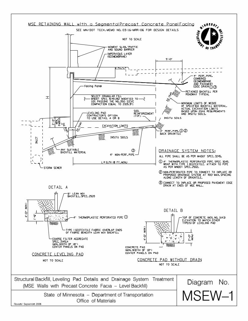
The foundation soils for the wall consist of mostly loose granular soils. The soils transition to a dense sand approximately elevation of 872 feet. Water was encountered at an approximate elevation of 861 feet. Please refer to the attached boring logs for a more complete description of the foundation soils.
Foundation Analysis
The wall is assumed to vary in height from 7-28 ft. Allowable bearing resistance for the foundation soils were calculated assuming a footing width equal to .7*Height of wall, a unit weight of fill of 125 pcf, and a safety factor of 2.5. Based on our analysis, the foundation soils have adequate bearing resistance to support the mechanically stabilized earth (MSE) wall on the in-place grannular soils.
SERRW2 69+92 to 73+32
Estimated Settlement
MSE Spread Footing -
Wall settlements were calculated based on the bearing pressures of the 28ft high MSE wall. In addition, our analysis was based on Meyerhof uniform redistribution of pressure over a reduced area at the base of the wall. Based on our analysis, we estimate that the wall will settle three to four inches with a maximum differential settlement of less than two inches between wall panels. This settlement should occur during construction and backfilling operations.
SERRW1 34+97 to 37+76
MSE Wall2 ft. Live Load Surcharge
fdn rec CIP TemplateSERRW1and2 .xls Page 1 of 1

Vane Shear Test Washed Sample (Collected during plug drilling)
Minnesota Department of Transportation Geotechnical Section
Boring Log Descriptive Terminology (English Units)
USER NOTES, ABBREVIATIONS AND DEFINITIONS - Additional information available in Geotechnical Manual. This boring was made by ordinary and conventional methods and with care deemed adequate for the Department's design purposes. Since this boring was not taken to gather information relating to the construction of the project, the data noted in the field and recorded may not necessarily be the same as that which a contractor would desire. While the Department believes that the information as to the conditions and materials reported is accurate, it does not warrant that the information is necessarily complete. This information has been edited or abridged and may not reveal all the information which might be useful or of interest to the contractor. Consequently, the Department will make available at its offices, the field logs relating to this boring. Since subsurface conditions outside each borehole are unknown, and soil, rock and water conditions cannot be relied upon to be consistent or uniform, no warrant is made that conditions adjacent to this boring will necessarily be the same as or similar to those shown on this log. Furthermore, the Department will not be responsible for any interpretations, assumptions, projections or interpolations made by contractors, or other users of this log. Water levels recorded on this log should be used with discretion since the use of drilling fluids in borings may seriously distort the true field conditions. Also, water levels in cohesive soils often take extended periods of time to reach equilibrium and thus reflect their true field level. Water levels can be expected to vary both seasonally and yearly. The absence of notations on this log regarding water does not necessarily mean that this boring was dry or that the contractor will not encounter subsurface water during the course of construction. WATER MEASUREMENT
Augered Plug Drilled Split Tube Sample (SPT N60 2 in. spilt tube with liners) Thin Wall Sample (3 in. Shelby Tube) Core Drilled (NV Core Barrel unless otherwise noted) Continuous Soil Sample Augered & Jetted Jetted Augered & Plug Drilled
WS
PD
CS
A/J Jet A/P
AB ........................ After Bailing AC ........................ After Completion AF......................... After Flushing w/C ....................... with Casing
Index Sheet No. 3.0 March 2003 G:\geotech\Public\Forms\INDEX30.doc
w/M ...................... with Mud WSD ..................... While Sampling/Drilling w/AUG.................. with Hollow Stem Auger MISCELLANEOUS NA ........................ Not Applicable w/ ......................... with w/o ....................... with out sat ........................ saturated DRILLING OPERATIONS AUG ................. Augered CD .................... Core Drilled DBD.................. Disturbed by Drilling DBJ .................. Disturbed by Jetting PD .................... Plug Drilled ST..................... Split Tube (SPT test) TW.................... Thinwall (Shelby Tube) WS.................... Wash Sample NSR.................. No Sample Retrieved
WH ................... Weight of Hammer WR ................... Weight of Rod Mud.................. Drilling Fluids in Sample CS .................... Continuous Sample SOIL/CORE TESTS SPT N60 ............ ASTM D1586 Modified Blows per foot with 140 lb. hammer and a standard energy of 210 ft-lbs. This energy represents 60% of the potential energy of the system and is the average energy provided by a Rope & Cathead system. MC.................... Moisture Content COH ................. Cohesion γ ....................... Sample Density LL..................... Liquid Limit PI...................... Plasticity Index Φ ...................... Phi Angle REC.................. Percent Core Recovered RQD ................. Rock Quality Description (Percent of total core interval consisting of unbroken pieces 4 inches or longer) ACL .................. Average Core Length (Average length of core that is greater than 4 inches long) Core Breaks .... Number of natural core breaks per 2-foot interval. DISCONTINUITY SPACING Fractures Distance Bedding Very Close........ <2 inches ............Very Thin Close ................ 2-12 inches .........Thin Mod. Close ....... 12-36 inches .......Medium Wide................. >36 inches ..........Thick DRILLING SYMBOLS
RELATIVE DENSITY Compactness - Granular Soils BPF
very loose....................................0-4 loose ...........................................5-10 medium dense ............................11-24 dense ..........................................25-50 very dense...................................>50
Consistency - Cohesive Soils BPF
very soft.......................................0-1 soft ..............................................2-4 firm ..............................................5-8 stiff ..............................................9-15 very stiff.......................................16-30 hard.............................................31-60 very hard .....................................> 60
COLOR blk .................. Black wht ...........White grn ................. Green brn............Brown orng ............... Orange yel.............Yellow dk ................... Dark lt ...............Light IOS ................. Iron Oxide Stained GRAIN SIZE /PLASTICITY VF............. Very Fine pl ............Plastic F ............... Fine slpl .........Slightly Cr ............. Coarse Plastic SOIL/ROCK TERMS C............... Clay Lmst .......Limestone L ............... Loam Sst ..........Sandstone S............... Sand Dolo........Dolostone Si.............. Silt wx...........weathered G .............. Gravel (No. 10 Sieve to 3 inches) Bldr .......... Boulder (over 3 inches) T ............... till (unsorted, nonstratified glacial deposits) Mn/DOT Triangular Textural Soil Classification System
100%
100%
C
90807060 50 40 302010
90
80
70
60
50
40
30
20
10
(plastic)
(slightly plastic)
SC
SCL CL
L SL SiL
Si
SiCL
LSS Si
90
80
70
60
50
40
30
20
10
100 %
% Sand % Clay
% Silt

Longitude (West)=93°23'34.12"
Bridge No. or Job Desc.
Latitude (North)=45°06'20.96"Completed 3/29/06
Drill Machine
Mobile Auto CalibratedHammer92730 Failing 1500 4x4
Hennepin Co. Coordinate: X=497552 Y=214750
SHEET 1 of 3Drilling
Location
US Highway 169State Project
2750-57Boring No.Trunk Highway/Location
3
(Survey)27R23
LS w/ a little G, dk brn & moist
(ft.)
S, lt gray-brn & damp
S w/ a little G, brn & moist
S & G, dk brn & moist
43
Ground Elevation
4
11
8
9
35
9
12.0874.7
7.0879.7
4.0882.7
TH 169 NB, 880+37.56, 94.9'Rt
15
or Member
T05
(psf)
UNIQUE NUMBER 67841
Other Tests
Classification
(%)MC
Or Remarks
MINNESOTA DEPARTMENT OF TRANSPORTATION - GEOTECHNICAL SECTIONLABORATORY LOG & TEST RESULTS - SUBSURFACE EXPLORATION
Elev. Breaks
Soil Class:DSB Rock Class: Edit: DMS Date: 11/28/06
COHDepth
(Continued Next Page)
SPT
U.S. Customary Units
REC
N
ACL(%)
5
10
15
20
DE
PTH
Formation(ft)
60 (pcf)
Roc
k
G:\GINT\PROJECTS-ACTIVE\2750-57.GPJ
(%)
Index Sheet Code 3.0
CoreRQD
Lith
olog
y
Dril
ling
Ope
ratio
n Soi
l
886.7

68
3
18
14
13
15
27R23Ground Elevation
(Survey)US Highway 169
21
22
Boring No.
2750-57State Project Bridge No. or Job Desc.
T05 886.7
Mn/DOT GEOTECHNICAL SECTION - LOG & TEST RESULTS SHEET 2 of 3
(%)
U.S. Customary Units
25
30
35
40
45
S, lt gray-brn & damp (continued)
S w/ a little G, seam CrS; brn & sat
S, brn & sat
92
Trunk Highway/Location
26.5860.2
36.0850.7
46.0840.7
22
Classification
Other Tests
MINNESOTA DEPARTMENT OF TRANSPORTATION - GEOTECHNICAL SECTIONLABORATORY LOG & TEST RESULTS - SUBSURFACE EXPLORATION
or Member
SPT
Elev.
UNIQUE NUMBER 67841
(Continued Next Page)
Or RemarksDepth
Breaks
Soil Class:DSB Rock Class: Edit: DMS Date: 11/28/06
COH
Dril
ling
Ope
ratio
n N
Formation
(pcf)
(ft)REC
(%)60 Soi
lMC(psf)
DE
PTH
Roc
kACL
G:\GINT\PROJECTS-ACTIVE\2750-57.GPJ
CoreRQD
Lith
olog
y
(%)

State Project
14
27R23Ground Elevation
(Survey)US Highway 169Trunk Highway/Location Boring No.
79
Bridge No. or Job Desc.
T05
Mn/DOT GEOTECHNICAL SECTION - LOG & TEST RESULTS
(%)
U.S. Customary Units
50
55
(%)
2750-57
S & G, brn & sat
S w/ a little G, brn & sat
S, brn & sat
Bottom of Hole - 59.0'Water level assumed to be at saturated granular layer
11
9
51.0835.7
56.0830.7
59.0827.7
61
57
SHEET 3 of 3
Other Tests
Soil Class:DSB Rock Class: Edit: DMS Date: 11/28/06
(ft)
886.7
MINNESOTA DEPARTMENT OF TRANSPORTATION - GEOTECHNICAL SECTIONLABORATORY LOG & TEST RESULTS - SUBSURFACE EXPLORATION
or MemberClassification
SPT
Elev.
Or Remarks
UNIQUE NUMBER 67841
DepthCOH
BreaksDril
ling
Ope
ratio
n (pcf)N60
FormationREC ACL
Soi
l
(%)MC
(psf)
DE
PTH
Roc
k
Lith
olog
y
G:\GINT\PROJECTS-ACTIVE\2750-57.GPJ
CoreRQD

3/27/06Mobile Auto CalibratedLongitude (West)=93°23'34.07"
92730 Failing 1500 4x4
2750-57SHEET 1 of 3
Latitude (North)=45°06'22.30"
DrillingLocation
(ft.)
TH 169 NB, 881+51.77, 25.7'Rt
11
8
Hennepin Co. Coordinate: X=497556 Y=214885
28R19Boring No.Trunk Highway/Location
US Highway 169 (Survey)
Completed
Ground Elevation
Drill Machine
slorg slpl SL w/ a few seams S, dk brn w/ brn, moist 13
5
S w/ a few thin seams slpl SL, gray-brns & moist
S to FS, brn, damp to moist
28.0
Hammer
14
12
15
10
8
858.8
6
22.0864.8
9.5877.3
30
DE
PTH
or Member
Other Tests
Classification
(%)MC
(psf) Or Remarks
MINNESOTA DEPARTMENT OF TRANSPORTATION - GEOTECHNICAL SECTIONLABORATORY LOG & TEST RESULTS - SUBSURFACE EXPLORATION
Elev. Breaks
Soil Class:DSB Rock Class: Edit: DMS Date: 11/28/06
COHDepth
(Continued Next Page)
UNIQUE NUMBER 67844
SPT
Roc
k
T10 886.8
60
(%)
5
10
15
20
25
N (pcf)
(%) (ft)Formation
Lith
olog
y
G:\GINT\PROJECTS-ACTIVE\2750-57.GPJIndex Sheet Code 3.0
U.S. Customary UnitsBridge No. or Job Desc.
RQD Core
Dril
ling
Ope
ratio
n Soi
l
ACLREC
State Project

(Survey)
(%)
42
24
38
47
45
21
10
16
12
11
S, gray-brn & sat
830.856.0
US Highway 169Trunk Highway/Location Boring No.
2750-57State Project Bridge No. or Job Desc.
T10 886.8
Mn/DOT GEOTECHNICAL SECTION - LOG & TEST RESULTS SHEET 2 of 3
Ground Elevation
S & G, brn & sat
slpl SL w/ a few pebbles, brn & Vmoist
mixed S & CrS, brn & sat
11
N/A
32.0854.8
36.5850.3
43.0843.8
U.S. Customary Units
Classification
Depth
MINNESOTA DEPARTMENT OF TRANSPORTATION - GEOTECHNICAL SECTIONLABORATORY LOG & TEST RESULTS - SUBSURFACE EXPLORATION
(%)SPT Other Tests
Elev.
28R19
or Member
Or Remarks
Breaks
Soil Class:DSB Rock Class: Edit: DMS Date: 11/28/06
UNIQUE NUMBER 67844
COH
(Continued Next Page)
REC(%) (ft)
(pcf)N
30
35
40
45
50
55
60
Formation
MC
Core
(psf)
DE
PTH
Roc
k
G:\GINT\PROJECTS-ACTIVE\2750-57.GPJ
ACLRQD
Lith
olog
y
Dril
ling
Ope
ratio
n Soi
l
heave to 33.0'

16
19
19
12
28R19Ground Elevation
(Survey)US Highway 169Boring No.
56
Bridge No. or Job Desc.
T10 886.8
Mn/DOT GEOTECHNICAL SECTION - LOG & TEST RESULTS SHEET 3 of 3
(%)
U.S. Customary Units
60
65
70
75
Trunk Highway/Location
FS, brn & sat
S w/ a few seams CrS, brn & sat
Bottom of Hole - 79.0'Water measured at 27.2' while sampling and/or drilling
18
37
61.0825.8
79.0807.8
69
47
41
State Project
Classification or Member
COH
MINNESOTA DEPARTMENT OF TRANSPORTATION - GEOTECHNICAL SECTIONLABORATORY LOG & TEST RESULTS - SUBSURFACE EXPLORATION
(%)
2750-57
Other TestsSPT
Elev.
Or Remarks
UNIQUE NUMBER 67844
Breaks
Soil Class:DSB Rock Class: Edit: DMS Date: 11/28/06
DepthACL
(ft)
(pcf)N60
FormationREC
(%) Soi
l
DE
PTH
Roc
k
MC(psf)
G:\GINT\PROJECTS-ACTIVE\2750-57.GPJ
CoreRQD
Lith
olog
y
Dril
ling
Ope
ratio
n

Minnesota Department of Transportation Geotechnical Section
Cone Penetration Test Index Sheet 1.0 (CPT 1.0)
USER NOTES, ABBREVIATIONS AND DEFINITIONS This Index sheet accompanies Cone Penetration Test Data. Please refer to the Boring Log Descriptive Terminology Sheet for information relevant to conventional boring logs. This Cone Penetration Test (CPT) Sounding follows ASTM D 5778 and was made by ordinary and conventional methods and with care deemed adequate for the Department's design purposes. Since this sounding was not taken to gather information relating to the construction of the project, the data noted in the field and recorded may not necessarily be the same as that which a contractor would desire. While the Department believes that the information as to the conditions and materials reported is accurate, it does not warrant that the information is necessarily complete. This information has been edited or abridged and may not reveal all the information which might be useful or of interest to the contractor. Consequently, the Department will make available at its offices, the field logs relating to this sounding. Since subsurface conditions outside each CPT Sounding are unknown, and soil, rock and water conditions cannot be relied upon to be consistent or uniform, no warrant is made that conditions adjacent to this sounding will necessarily be the same as or similar to those shown on this log. Furthermore, the Department will not be responsible for any interpretations, assumptions, projections or interpolations made by contractors, or other users of this log. Water pressure measurements and subsequent interpreted water levels shown on this log should be used with discretion since they represent dynamic conditions. Dynamic Pore water pressure measurements may deviate substantially from hydrostatic conditions, especially in cohesive soils. In cohesive soils, water pressures often take extended periods of time to reach equilibrium and thus reflect their true field level. Water levels can be expected to vary both seasonally and yearly. The absence of notations on this log regarding water does not necessarily mean that this boring was dry or that the contractor will not encounter subsurface water during the course of construction. CPT Terminology CPT .............Cone Penetration Test CPTU...........Cone Penetration Test with Pore Pressure measurements SCPTU.........Cone Penetration Test with Pore Pressure and Seismic measurements Piezocone...Common name for CPTU test (Note: This test is not related to the Dynamic Cone Penetrometer DCP) qT TIP RESISTANCE The resistance at the cone corrected for water pressure. Data is from cone with 60 degree apex angle and a 10 cm2 end area. fs SLEEVE FRICTION RESISTANCE The resistance along the sleeve of the penetrometer. FR Friction Ratio
Ratio of sleeve friction over corrected tip resistance. FR = fs/qt Vs Shear Wave Velocity A measure of the speed at which a siesmic wave travels through soil/rock. PORE WATER MEASUREMENTS Pore water measurements reported on CPT Log are representative of water pressures measured at the U2 location, just behind the cone tip, prior to the sleeve, as shown in the figure below. These measurements are considered to be dynamic water pressures due to the local disturbance caused by the cone tip. Dynamic water pressure decay and Static water pressure measurements are reported on a Pore Water Pressure Dissipation Graph.
SBT SOIL BEHAVIOR TYPE Soil Classification methods for the Cone Penetration Test are based on correlation charts developed from observations of CPT data and conventional borings. Please note that these classification charts are meant to provide a guide to Soil Behavior Type and should not be used to infer a soil classification based on grain size distribution. The numbers corresponding to different regions on the charts represent the following soil behavior types: 1. Sensitive, Fine Grained 2. Organic Soils - Peats 3. Clays - Clay to Silty Clay 4. Silt Mixtures - Clayey Silt to Silty Clay 5. Sand Mixtures - Silty Sand to Sandy Silt 6. Sands - Clean Sand to Silty Sand 7. Gravelly Sand to Sand 8. Very Stiff Sand to Clayey Sand 9. Very Stiff, Fine Grained Note that engineering judgment, and comparison with conventional borings is especially important in the proper interpretation of CPT data in certain geo-materials. The following charts are used to provide a Soil Behavior Type for the CPT Data. Robertson CPT 1990 Soil Behavior type based on friction ratio
Robertson CPTU 1990 Soil Behavior type based on pore pressure
U2
where ... .......................... normalized cone resistance QT
.......................... pore pressure ratio BBq
........................... Normalized friction ratio Fr
........................ overburden pressure σvo
σ’vo ....................... effective over burden pressure u .......................... measured pore pressure 2
.......................... equilibrium pore pressure u0 G:\GEOTECH\PUBLIC\FORMS\CPTINDEX.DOC January 30, 2002

End of Data
0
5
10
15
20
25
UNIQUE NUMBER 68233CONE PENETRATION TEST RESULTS
CPT Operator(ft.)
SHEET 1 of 2
Latitude (North)=45°06'22.96"
99649 CPT TrackCPT MachineLocation
Index Sheet Code 3.0
Date Completed2980.106XX
Hennepin Co. Coordinate: X=497797 Y=214952
MINNESOTA DEPARTMENT OF TRANSPORTATION - GEOTECHNICAL SECTION
0 2 4 6 8 10 0 2 4 6 8 101200 2400 3600 4800 600020 16 12 8 4 0 0 20 40 60 801200 2400 3600 4800 6000
(Continued Next Page) Soil Class: Rock Class: Edit: Date: 11/28/06
U.S. Customary Units
885.5
880.5
875.5
870.5
865.5
860.5
G:\GINT\PROJECTS-ACTIVE\2750-57.GPJ
Cone #
Bridge No. or Job Desc.
2750-57
Depth Pore Pressure(psi)UBC 1990 FR
Tip Resistance(psi)
, , ft. LTlueck
5/18/06Longitude (West)=93°23'30.71"
US Highway 169Sounding No.
Ret WallState Project
885.5
Sleeve Friction(psi)
Interpreted SoilBehavior Type Friction Ratio
(%)
Trunk Highway/Location
c014Ground Elevation
Elevation
(from Plan)
A18Y0601C.DAT

Interpreted SoilBehavior Type Friction Ratio
(%)
Trunk Highway/Location
c014Ground Elevation
Elevation
Sounding No.
2750-57
Bottom of Hole 29.86801
State Project
Depth Pore Pressure(psi)UBC 1990 FR
Tip Resistance(psi)
Bridge No. or Job Desc.
Mn/DOT GEOTECHNICAL SECTION - CONE PENETRATION TEST RESULTS SHEET 2 of 2
U.S. Customary Units
0 2 4 6 8 10 0 2 4 6 8 101200 2400 3600 4800 600020 16 12 8 4 0 0 20 40 60 801200 2400 3600 4800 6000
Sleeve Friction(psi)
MINNESOTA DEPARTMENT OF TRANSPORTATION - GEOTECHNICAL SECTION
885.5
G:\GINT\PROJECTS-ACTIVE\2750-57.GPJ
UNIQUE NUMBER 68233CONE PENETRATION TEST RESULTS
US Highway 169 (from Plan)Ret Wall
A18Y0601C.DAT Soil Class: Rock Class: Edit: Date: 11/28/06

Bottom of Hole 41.136
End of Data
D BradyTH 169 NB, 882+36.19, 76.4'Rt
Cone #
CPT Operator
2579.111XXDate Completed
Index Sheet Code 3.0
Location CPT Machine 203094 CPT Truck
Latitude (North)=45°06'22.78"
SHEET 1 of 1
State Project Ground Elevation
C119Trunk Highway/Location
Friction Ratio(%)
Interpreted SoilBehavior Type
885.8
Hennepin Co. Coordinate: X=497643 Y=214934
Ret Wall (from Plan)US Highway 169
Longitude (West)=93°23'32.86" 11/30/04
Sleeve Friction(psi)
20 16 12 8 4 0
MINNESOTA DEPARTMENT OF TRANSPORTATION - GEOTECHNICAL SECTION
Soil Class: Rock Class: Edit: DMS Date: 11/28/06
0 20 40 60 801200 2400 3600 4800 6000 0 2 4 6 8 100 2 4 6 8 10 1200 2400 3600 4800 6000
CONE PENETRATION TEST RESULTS
0
5
10
15
20
25
30
35
40
G:\GINT\PROJECTS-ACTIVE\2750-57.GPJ
885.8
880.8
875.8
870.8
865.8
860.8
855.8
850.8
845.8
U.S. Customary Units
(ft.)
UNIQUE NUMBER 66535
Elevation
Bridge No. or Job Desc.
Tip Resistance(psi)
Pore Pressure(psi)
Depth
2750-57Sounding No.
UBC 1990 FR
B30N0405C
5’-0"
INL
ET
2’-
0"
INSITU SOILS
INSITU SOILS
MOMENT SLAB, TRAFFIC
AND SOUND BARRIER
ANY SUITABLE
BACKFILL MATERIAL
MIN
.
EM
BE
D.
DRAINAGE SYSTEM NOTES:
1
1
1
MINIMUM LIMITS OF WEDGE
OF SPECIFIED BACKFILL MATERIAL.
ACTUAL EXCAVATION LIMITS
BASED UPON OSHA REQUIREMENTS
AND INSITU SOILS.
STORM SEWER
4" NON-PERF. PIPE
2
ALL PIPE SHALL BE AS PER MnDOT SPEC. 3245.
2
4" PERF. PIPE.
BACK DRAINTILE
2
3
3
4" THERMOPLASTIC PERFORATED PIPE, SPEC. 3245,
WRAP WITH TYPE I GEOTEXTILE. ATTACH TO PIPE
AS PER MNDOT SPEC. 2502.
NON-PERFORATED PIPE TO CONNECT TO INPLACE OR
PROPOSED DRAINAGE SYSTEM AT 400’ MAX. SPACING
ALONG LENGTH OF DRAINTILE.
CONNECT TO INPLACE OR PROPOSED PAVEMENT EDGE
DRAIN AT ENDS OF MSE WALL.
4" PERF. PIPE.
COMBINED
GEOMEMBRANE
AND PAVEMENT
EDGE DRAIN
MSEW-1
Diagram No.
NOT TO SCALE
M
INNESOTA
DE
PA
RT
ME
NT OF TRANS
PO
RT
ATIO
N
Structural Backfill, Leveling Pad Details and Drainage System Treatment
State of Minnesota - Department of Transportation
Office of Materials
NOT TO SCALE
NOT TO SCALE
CONCRETE PAD WITHOUT DRAIN
(MIN
.)
TOP OF CONCRETE (MIX. NO. 1A43)
ELEVATION TO MATCH OTHER
TYPE(S) OF LEVELING PAD
Revised September 2005
DETAIL A
DETAIL B
H
2:1
(V
:H)
2:1
(V
:H)2
:1 (V
:H)
14" THERMOPLASTIC PERFORATED PIPE
SELECT GRANULAR FILL
MNDOT SPEC. 3149.2B2 MODIFIED TO
10% PASSING THE NO. 200 SIEVE
COMPACTION EQUAL TO 2105.3F1
TYPE i GEOTEXTILE FABRIC (OVERLAP ENDS
OF FABRIC BENEATH LEAN MIX BACKFILL
COARSE FILTER AGGREGATE
SPEC. 3149.H
(MIN. WIDTH OF 18")
CENTER PANELS ON PAD
MSE RETAINING WALL with a Segmental Precast Concrete Panel Facing
SEE MN/DOT TECH. MEMO NO. 03-16-MRR-06 FOR DESIGN DETAILS
(MSE Walls with Precast Concrete Facia - Level Backfill)
L 0.7H (8 FT. MIN.)
Facing Panel
CONCRETE PAD
(MIN. WIDTH OF 18")
CENTER PANELS ON PAD
IMPERVIOUS LAYER
(GEOMEMBRANE)
RETAINED BACKFILL PER
ROADWAY TYPICAL
SOIL
REINFORCEMENT
(TYP.)
EXCAVATION LIMITS
2’-
0"
4’-
0"
1’-
6"
4’-
0"
(MIN
.)
(MIN
.)
CONCRETE LEVELING PAD
6" LEAN MIX
BACKFILL, SPEC. 2520
LEVELING PAD
CONTRACTOR’S OPTION
TO USE DETAIL A OR B

5’-0"
INSITU SOILS
MINIMUM LIMITS OF WEDGE
OF SPECIFIED BACKFILL MATERIAL.
ACTUAL EXCAVATION LIMITS
BASED UPON OSHA REQUIREMENTS
AND INSITU SOILS.
Diagram No.
M
INNESOTA
DE
PA
RT
ME
NT OF TRANS
PO
RT
ATIO
N
State of Minnesota - Department of Transportation
Office of MaterialsRevised September 2005
H
2:1
(V
:H)
(MSE Walls with Precast Concrete Facia - Level Backfill)
RETAINED BACKFILL PER
ROADWAY TYPICAL
1’-6"
2:1
ALL SLOPE DIMENSIONSSHOWN AS V:H
INSITU SOILS INSITU SOILS
SUBCUT EXCAVATION LIMITS
L 0.7H (8 FT. MIN.)
MSE RETAINING WALL FOUNDATION SUBCUT DETAILS
2:1
BACKFILL WITH GRANULAR BORROWMn/DOT SPEC. 3149.2B1
Subcut Excavation and Backfill Details
MSEW-1s
NOT TO SCALE
PAY LIMITS FOR STRUCTURAL EXCAVATION
WHEN A SUBCUT IS REQUIRED. ACTUAL
EXCAVATION SLOPE IS DETERMINED BY
OSHA REGULATIONS AND IN-SITU SOILS.

65
65
15
55
{ B
RA
ID
{ N
B8
1
{ S
B169
{ S
ER
RW
2
{ S
ER
RW
1
410
410
52
20
35
70
C232
C233
C234
A
7000X2
A
7029
7058
A
7059
A
7083
A
7084
A
7085
A
7086
7102
A
7130
A
7131
A
7132
A
7200
A
7201
A
7202
C020
C021
C028
C119
T10
T5
c014
36 37
TOP OF RAIL
INPLACE GROUNDLINEFINISHED GROUNDLINE
(WEST SIDE OF WALL)
TOP OF BARRIER SLAB
STA. 35+40.00
EL. 904.70
STA. 36+50.00
EL. 901.08
STA. 37+75.76
EL. 896.16
STA. 34+97.06
EL. 906.12
STA. 35+30.00
EL. 904.79
2’ BELOW FINISHED GROUNDLINE
(FOR ESTIMATED WALL AREA)
910
900
890
880
870
860
850
840
830
820
RETAINING WALL SERRW1 PROFILE
34 ft. left
40 ft. left
85 ft. right
Tip Stress (psi)
5 10
FR (%)
50
10
0
3000
6000
PWP (psi)
c014 - #68233 - 885.5
Tip Stress (psi)
5 10
FR (%)
50
10
0
3000
6000
PWP (psi)
C119 - #66535 TH 169 NB, 882+36.19, 76.4’Rt - 885.8
Coh SPT
LS w/ a little G, dk brn
& moist
S & G, dk brn & moist
S w/ a little G, brn &
moist
S, lt gray-brn & damp
S w/ a little G, seam
CrS; brn & sat
S, brn & sat
S & G, brn & sat
S w/ a little G, brn & sat
S, brn & sat
Bottom of Hole - 59.0’
Water level assumed to
be at saturated granular
layer
43
9
15
35
22
22
21
92
68
61
57
79
T05 - #67841 TH 169 NB, 880+37.56, 94.9’Rt - 886.7
Coh SPT
slorg slpl SL w/ a few
seams S, dk brn w/ brn,
moist
S to FS, brn, damp to
moist
S w/ a few thin seams
slpl SL, gray-brns &
moist
S, gray-brn & sat
S & G, brn & sat
slpl SL w/ a few
pebbles, brn & Vmoist
mixed S & CrS, brn &
sat
FS, brn & sat
S w/ a few seams CrS,
brn & sat
Bottom of Hole - 79.0’
Water measured at
27.2’ while sampling
and/or drilling
30
8
10
15
12
11
42
24
38
47
45
69
47
41
56
37
T10 - #67844 TH 169 NB, 881+51.77, 25.7’Rt - 886.8
35 38