Embed Size (px)
Citation preview
MINISTRY OF EDUCATION AND SCIENCE YOUTH AND SPORT OF
UKRAINE
VLADIMIR DAHL EAST UKRAINIAN NATIONAL UNIVERSITY
FACULTY OF ELECTRICAL SYSTEMS
Department of electrotechnical system of power consumption
EXPLANATORY NOTE
of masterrsquos thesis on the topic
INCREASING OF EFFICIENCY OF INDUSTRIAL ENTERPRISES BY
REDUCING OF ENERGY LOSSES IN THE POWER EQUIPMENT
MT 101101000 EN
The student of ETndash101m _________________________AL-Majidi Sadeq (signature date)
Scientific Head __________________________________ Kuzmenko DI (signature date)
Consultant of labor safety ____________________________ Kas`yanov NA (signature date)
Head of department ________________________________ Zakharchuk AS (signature date)
Lugansk 2012
MINISTRY OF EDUCATION AND SCIENCE YOUTH AND SPORT OF
UKRAINE
VLADIMIR DAHL EAST UKRAINIAN NATIONAL UNIVERSITY
Faculty electrical systems
Department electrotechnical system of power consumption
Speciality
1 Student AL-Majidi Sadeq
electrotechnical system of power consumption
ldquoConfirmrdquo
Head of department ________________ Zakharchuk AS (signature date)
ldquo____rdquo ______________ 2012
Task for the masters thesis
2 Group ET-101m
3 Topic Increasing of efficiency of industrial enterprises by reducing of
energy losses in the power equipment
4 Tasks for the masterrsquos thesis
- Calculation and selection of main power supply elements of industry
- Analysis of implementation of methods of power loss reduction
-
5 Contents (the main questions) ndash according to plan
6 Graph materials
1 Plan-scheme of industry power supplyOne-line principal scheme of
industry
2 Day load diagrams of workshops
3 Day load diagrams of industry
4 Effect of implementation of losses reduction methods
5 Expediencyof cable cross section
6 Consultant
Chapter Consultant Signature
1 ndash 4 Kuzmenko DI
5 Labor safety Kas`yanov MA
7 Plan
Name of the chapter Date
1 Chapter 1 (PROBLEMS AND TASKS OF THE RESEARCH)
2 Chapter 2 (CALCULATION OF ELECTRIC LOAD)
3 Chapter 3 (DESIGN AND TECHNICAL AND ECONOMIC CALCULATION OF EXTERNAL ELECTRICAL)
4 Chapter 4 (REDUCING OF POWER LOSS BY SMOOTHING OF DAY
LOADS GRAPH)
5 Chapter 5 (TECHNICAL CALCULATION OF INTERNAL POWER SUPPLY)
6 Chapter 6 (LABOR SAFETY)
7 (Execution of the work according to ISO)
Student ____________________
Scientific Head ___________________
Date ldquo____rdquo ___________2012
ABSTRACT
In first chapter types of power losses were analazed Places of power losses were
researched Methods of losses reduction were analized
In second chapter calculations of loads of industry were implemented Compensating
devises were selected Effect of compensation was analized
In third chapter feed voltage main step-down transformers were selected
In fourth chapter method of smoothing of day load graph was analized Original and
smoothed day load graphs were built and analized Specified selection of transformers
rated capacity was performed Optimal operation mode was selected
In fifth chapter internal power supply scheme was selected Preliminary and specified
selection of cross section was performed
In sixth chapter calculation of lighting protection and earthing devices were
performed
The work consists of introduction 6 chapters and conclusions Full scope of work
includes 111 pages 46 figures 6 of them on separate sheets and 48 tables The reference
includes 39 items
POWER LOSSES POWER SUPPLY REDUCING OF LOSSES
TRANSFORMERS POWER CABLE LOAD GRAPH SMOOTHING OF LOAD
SELECTION OF CROSS SECTION
Змн Арк докум Підпис Дата Арк
MT 101101000 EN Розроб Al-magidi S
Перевір Kuzmenko DI Реценз Н Контр Затверд Zakharchuk AS
Increasing efficiency of industrial
enterprises by reducing energy
losses in the power equipment
Літ Акрушів
V Dahl ENU chair ESPC
Contents INTRODUCTION 6 1 PROBLEMS AND TASKS OF THE RESEARCH 8
11 Problem of power losses in power engineering 8 12 Places of power losses 10
13 Methods of reducing of power losses 15 14 Task of the research 25
2 CALCULATION OF ELECTRIC LOAD 26 21 Calculation of electric load plant 1 without illumination 26 22 Calculation of electrical loads for workshopsrsquo group 31 23 Selection of compensating devices 34
3 DESIGN AND TECHNICAL AND ECONOMIC CALCULATION OF EXTERNAL ELECTRICAL
56
31 Checking of main power transformer of 110 kV 61
32 Checking of main power transformer of 35 kV 63 33 Selection of feed voltage 65 4 REDUCING OF POWER LOSS BY SMOOTHING OF DAY LOADS GRAPH 66 41 Smoothing of load by moving of shifts 66
42 Calculation of power loss for original operation mode 70
33 Calculation of power loss for smoothed operation mode 78
5 TECHNICAL CALCULATION OF INTERNAL POWER SUPPLY 87
41 Selection of the section of cable lines 88
42 Expediency of cable cross section 94
6 LABOR SAFETY 97
61 Protection against direct lightning hit 97
62 Calculation of earthing devices 102
Conclusions 107
References 108
6 Змн Арк докум Підпис Дата
Арк
MT 101101000 EN
INTRODUCTION
In modern conditions of complete and total economization of all areas one of the
most important tasks of modern power engineering is to minimize losses and
consequently costs In connection with the development of market relations in the country
the significance of the problem of loss of electricity has increased substantially
Development of methods of calculation analysis of energy losses and the choice of cost-
based measures to reduce them is more than 30 years Due to the complexity of calculating
the losses and the presence of significant errors in the recent emphasis on developing
methods of normalization of energy losses
The simplest and most effective way to reduce losses is to build an effective and
competent power supply of industrial enterprises which can be attributed to the largest
loads in the network and consequently to the greatest sources of loss Therefore the
management of industrial enterprises (especially private enterprises) should be interested
in activities that reduce the power losses in the equipment
In power supply to final consumers losses refer to the amounts of electricity
injected into the transmission and distribution grids that are not paid for by users Total
losses have two components technical and non-technical Technical losses occur naturally
and consist mainly of power dissipation in electricity system components such as
transmission and distribution lines transformers and measurement systems Non-technical
losses are caused by actions external to the power system and consist primarily of
electricity theft non-payment by customers and errors in accounting and record-keeping
These three categories of losses are respectively sometimes referred to as commercial
non-payment and administrative losses although their definitions vary in the literature
Metering and billing for electricity actually consumed by users is integral to
commercial management of an electricity utility Another critical task is collection of the
billed amounts Effective performance in both functions is critical to ensure the financial
viability of the company From the operational point of view metering-billing and
collection are separate functions and they require specific management approaches
So power losses in electrical networks - a key indicator of efficiency of their work
a clear indicator of the state accounting system of electricity the efficiency of energy sales
Змн Арк докум Підпис Дата
pag
MT 101101000 EN
of power supply companies This indicator shows the problems that require urgent
solutions in development reconstruction and technical re-equipment of electrical
networks methods and means of improving their operation and management to improve
the precision metering of electricity the efficiency of collecting money for the electricity
supplied to consumers etc
Methodology for determining standards of losses has not yet been established Do
not even defined the principles of valuation Views on approach to rationing are a wide
range - from the desire to have established a firm standard as a percentage of loss to
control the normal losses with the help of calculations carried out continuously by the
schemes of networks using appropriate software According received norms established
electricity losses in electricity tariffs Energy suppliers must justify the level of energy
losses which they consider appropriate to include in the tariff and the energy commission
- to analyze these studies and to accept or adjust them
Analysis of foreign experience shows that the growth of electricity losses in
networks - an objective process for countries with economies in crisis and reformed
energy a sign of the existing gaps between solvency and consumer rates for electricity the
rate of under-investment in network infrastructure and system metering lack of full-scale
automated information systems for the collection and transfer of useful data on electricity
supply the structure of the flow of electricity on the steps of the voltage power balances
in electric networks
In countries where these factors occur the loss of power in networks tends to have
high and growing
The cost of losses - is part of the costs of transmission and distribution of electricity
to the grid The greater the loss the higher these costs and thus electricity prices for
consumers It is known that some of the losses is a technological power consumption
required to overcome the resistance of the network and delivery to consumers of electricity
generated by power plants This technology required energy consumption to be paid by the
consumer It in essence is the norm loss
Змн Арк докум Підпис Дата
pag
MT 101101000 EN
1 PROBLEMS AND TASKS OF THE RESEARCH
11 Problem of power losses in power engineering
The issue of limited resources in todays world is one of the most pressing The
constant increase of production which is characteristic for the global industry as the
intensive and extensive way in most cases leads to an increase in power consumption
This creates a shortage of energy resources
The division of natural resources in inexhaustible and exhaustible is becoming
more tentative Many types of resources are now moving from the first into the second
category
The main type of energy is still mineral fuels - oil gas and coal These non-
renewable energy sources and at the present rate of growth of their production they may
be exhausted by 80-140 years However the proportion of these sources must be reduced
through the development of nuclear energy based on the use of heavy fuel - fissile
isotopes of thorium and uranium However these non-renewable resources the scientists
calculations only enough uranium for several decades Also by order of the European
Union the construction of nuclear power is suspended which increases the need for fossil
fuel Energy shortages in turn will significantly increase the cost for exhaustible
resources
At this point the specific consumption of fuel produced at the 1 kWh is 200-
400 g kWh The need for power produced from the power of one million kWh is
11-13 tons per day
Thus the problem of reducing the power loss is becoming increasingly important
for both private and state-owned enterprises
Power losses in electrical networks - a key indicator of efficiency of their work a
clear indicator of the state accounting system of electricity the efficiency of energy sales
of power supply companies
Змн Арк докум Підпис Дата
pag
MT 101101000 EN
This indicator is all the clearer indicates the cumulative problems that require
urgent solutions in development reconstruction and technical re-equipment of electrical
networks methods and means of improving their operation and management to improve
the precision metering of electricity the efficiency of collecting money for the electricity
supplied to consumers etc
According to international experts the relative power losses during transmission
and distribution in networks of most countries can be considered satisfactory if they do not
exceed 4-5 The loss of electricity at 10 can be considered as acceptable from the
standpoint of physics transmission over networks
It is becoming increasingly clear that the aggravation of the problem of reducing
the energy losses in electric networks require an active search for new ways to solve it
new approaches to the selection of appropriate activities and most importantly the
organization works to reduce losses
Due to the sharp decline in investment in the development and modernization of
power grids in the improvement of their management regimes measurement equipment a
number of negative trends affecting the level of losses in the networks such as outdated
equipment physical and moral deterioration of electricity metering discrepancy the
equipment installed transmission capacity
From the aforementioned it follows that on the background of a changing
economic mechanism in the energy sector the economic crisis in the country the problem
of reducing energy losses in electric networks not only has not lost its relevance but
instead popped into one of the tasks of ensuring the financial stability of power supply
companies
Змн Арк докум Підпис Дата
pag
MT 101101000 EN
12 Places of power losses
After electric power is generated it is sent through the transmission linesto the
many distribution circuits that the utility operates The purpose of thedistribution system is
to take that power from the transmission system anddeliver it to the consumers to serve
their needs However a significant portion ofthe power that a utility generates is lost in the
distribution process These lossesoccur in numerous small components in the distribution
system such astransformers and distribution lines Due to the lower power level of
thesecomponents the losses inherent in each component are lower than those
incomparable components of the transmission system While each of thesecomponents
may have relatively small losses the large number of componentsinvolved makes it
important to examine the losses in the distribution systemThese losses typically account
for approximately four percent of the total systemload
There are two major sources of losses in power distribution systemsThese are the
transformers and power lines Additionally there are two majortypes of losses that occur
in these components These losses are often referred toas core losses and copper or
I2Rlosses Core losses in transformers account forthe majority of losses at low power
levels As load increases the copper lossesbecome more significant until they are
approximately equal to the core losses atpeak load
The economic implications of these losses are far reaching In addition tothe
excess fuel cost needed to cover the lost energy added generating capacitymay be needed
Also the power lost in the distribution system must still betransmitted through the
transmission system which further adds to the loss in thatsystem It is very important for
electric power suppliers to consider these lossesand reduce them wherever practical
Losses in Distribution Lines
One of the major sources of losses in the distribution system is the powerlines
which connect the substation to the loads Virtually all real power that islost in the
distribution system is due to copper losses Since these losses are afunction of the square
Змн Арк докум Підпис Дата
pag
MT 101101000 EN
of the current flow through the line it should be obviousthat the losses in distribution lines
are larger at high power levels than they are atlower levels
Since power loss in the distribution lines can be considered to be entirelydue to
copper losses it can be calculated using formula
P=I2R (11)
From this it is apparent that anything that changes either current or lineresistance
will affect the amount of power lost in the line
The primary determining factor for the magnitude of line current is theamount of
real and reactive power loading at the end of the line As the powerthat is transmitted
along the line increases the current flow in the line becomeslarger Another factor which
affects the level of current flow is the operatingvoltage of the line For a given real and
reactive power load level S a highvoltage line will have a lower current than a low
voltage line This can be seenfrom formula
S=UI (12)
Therefore for a given power level the higher voltage line will have lower
copperlosses
Another factor which can result in higher line losses is unbalancedloading If one
of the phases is loaded more heavily than the others the loss willbe larger than it would
have been in the balanced load case This is due to thesquaring of the current in (11) For
instance if one line carries twicethe current of the other two and all other factors are kept
constant an increase incopper loss of 125 occurs compared to the balanced load case
While the current level has the biggest effect on line loss the resistance ofthe line
cannot be neglected The line resistance depends on many factorsincluding the length of
the line the effective cross-sectional area and theresistivity of the metal of which the line
is made The resistance is inverselyproportional to the cross-sectional area and directly
proportional to both thelength and resistivity This is shown in 13 below where R is
Змн Арк докум Підпис Дата
pag
MT 101101000 EN
theresistance ρ is the resistivity L is the length of the line and A is the effectivecross-
sectional area
R=ρLA (13)
Therefore a long line will have a higher resistance and larger losses than a
shortline with the same current flow Similarly a large conductor size results in asmaller
resistance and lower losses than a small conductor
The resistivity is determined by the material of which the line isconstructed and the
temperature of the material A better conducting material willresult in lower resistivity and
lower losses The resistivity of the metal in the linewill be affected by the temperature As
the temperature of the metal increasesthe line resistance will also increase causing higher
copper losses in thedistribution line The resistivity of copper and aluminum can be
calculated from
(14)
Losses in Distribution Transformers
While losses in distribution lines are virtually all due to copper lossestransformer
losses occur due to both copper and core losses The core losses aremade up of eddy
current and hysteresis losses The copper losses in transformersare essentially the same as
those in the power distribution lines
The copper losses in a transformer are smaller in magnitude than the corelosses
These losses occur in the form of heat produced by the current bothprimary and
secondary through the windings of the transformer Like the copperloss in the distribution
line it is calculated using the P=I2Rrelationship of 11 Any factor which affects either
current or winding resistance will alsoaffect the amount of copper loss in the transformer
Змн Арк докум Підпис Дата
pag
MT 101101000 EN
An increase in loading either real or reactive will result in an increase incurrent
flow and a correspondingly greater amount of loss in the transformerAdditionally an
unbalanced system load will increase transformer loss due to thesquared current
relationship The winding resistance also has an effect on theamount of copper loss and is
mainly determined by the total length of the wireused as well as the size of the wire The
temperature of the winding will affectthe resistivity of the wire therefore affecting the
overall resistance and thecopper loss Since all but the smallest distribution transformers
have some typeof cooling system such as immersion in oil the temperature effect on
losses isusually minimal
The core loss in a transformer is usually larger in magnitude than thecopper loss It
is made up of eddy current losses which are due to magneticallyinduced currents in the
core and hysteresis losses which occur because of theless than perfect permeability of the
core material These losses are relativelyconstant for an energized transformer and can be
considered to be independentof the transformer load Transformer core losses have been
modeled in variousways usually as a resistance in parallel with the transformers
magnetizingreactance
Since the core loss is relatively independent of loading the most importantfactor
when considering core loss is the manufacture of the core The physicalconstruction of the
core has serious consequences on the amount of core lossoccurring in the transformer For
instance eddy currents are greatly reduced byusing laminated pieces to construct the core
These thin sheets are oriented alongthe path of travel of the magnetic flux and restrict the
amount of induced currentsthat occur
The hysteresis loss occurs in the transformer core due to the energyrequired to
provide the magnetic field in the core as the direction of magneticflux alternates with the
alternating current wave form This energy is transformedinto heat Hysteresis loss can be
reduced by the use of higher quality materials inthe core which have better magnetic
permeability Many advanced core materialshave been developed recently with claims of
core loss reductions in the range of50 and above
Змн Арк докум Підпис Дата
pag
MT 101101000 EN
A final aspect of the distribution system that increases losses in thetransformers is
the presence of harmonics in the system The harmonic currentsonly cause a small increase
in copper losses throughout the system However thehigh frequency harmonic voltages
can cause large core losses in the transformerFrequently utilities are forced to use an
oversized transformer to compensatewhen a large harmonic presence is indicated The
increased skin effect of largerconductors combined with the high frequency harmonics can
result in evengreater losses
Losses due to nonoptimal modes of electrical networks the errors of measurement
equipment deficiencies in the power sales activities are the direct loss of power supply
organizations and of course must be reduced
Therefore normative power losses of industrial enterprises can be divided into quasi-
constant and loading
Quasi-constant losses
- on the crown
- in steel of transformers
- in compensating devices
- in the accounting system
- in the valve and surge arresters
- in the cable insulation
- from the leakage of overhead insulators
- own demands of substations
- melting ice
Loading losses
- in line
- in transformers
- in current-limiting reactors
Змн Арк докум Підпис Дата
pag
MT 101101000 EN
Excessive losses include
- low level of reactive power compensation
- nonoptimal operation of networks due to overload and underload equipment
- poor technical condition equipment
- outdated equipment with high power consumption
- inefficient networking
13 Methods of reducing of power losses
According to international experts the relative power losses during transmission
and distribution in networks of most countries can be considered satisfactory if they do not
exceed 4-5 The loss of electricity at 10 can be considered as acceptable from the
standpoint of physics transmission over networks This is confirmed by the pre-crisis level
of energy losses in most of the power of the former Soviet Union which does not exceed
usually 10 Since today the rates are increased by 15-2 and the electric grid for
individual companies - even three times it is obvious that in the context of the economic
mechanism of change in energy economic crisis in the country the problem of reducing
energy losses in electric networks not only lost its relevance and vice versa - has popped
into one of the tasks of ensuring the financial stability of organizations
Technical
- Optimization of the power networks load due to construction of transmission
lines and substations
- Replacement of overloaded and underloaded power networks equipment
- Commissioning of electric energy saving equipment
Змн Арк докум Підпис Дата
pag
MT 101101000 EN
Organizational
- Optimization of circuits and modes of supply
- Reduction of electrical systems repairs
- Commissioning of unused auto-regulation of load equalization of asymmetric
loads phase and so on
Measures to improve the design of systems and technical accounting of energy
- Conducting raids to identify unrecorded electricity
- Improving the system for collecting indications of counters
- To ensure normal working conditions of metering devices
- The replacement modernization installation of the missing meters
Compensating of reactive power
In electrical circuits with a purely resistive load flowing current is not leading and
lagging the voltage Inductive load current lags the voltage the capacitance leads voltage
At work electric motors compressors electromagnets etc that the most typical of most
consumer load is inductive and the total power consumption of reactive power is present
In this case the power factor is reduced and its increasing need to connect a capacitive
load which compensates for the inductive component The resulting load is closer to a
purely active power factor and takes the maximum value For reactive power
compensation condenser units are used in the automatic mode increasing the power factor
and thereby reduce the overall losses of the consumer In particular with an increase in the
power factor from 05 to 09 reactive power is reduced by 44
The need for energy conservation is becoming increasingly important This is due
to the increasing deficit and increasing energy costs growth of production and urban
infrastructure The majority of consumers consume along with active power and reactive
power which is spent on the creation of electromagnetic fields and is useless The
presence of reactive power supply reduces the quality of electricity leads to an increase in
Змн Арк докум Підпис Дата
pag
MT 101101000 EN
charges for electricity additional losses and overheating of wires overloaded substations
need to over-capacity power transformers and cable cross-sections subsidence voltage
sources
The use of condensing units allows to reduce the amount of reactive power
consumption and achieve economic benefits in terms of energy savings
There are several ways to reduce reactive power but the use for these purposes is
condensing units is preferred Condensing units have low loss ease of setup and operation
they can be plugged into any power point They can be used to compensate for almost any
amount of reactive power The payback period condensing units is less than years and in
some cases no more than several months
In the future we should expect a further increase of tariffs on the consumption of
reactive power
Implementation of condensing units will help to avoid subsidence voltage on
power lines of remote users will reduce the amount of payment for electricity to ensure
power supply cable with a smaller cross-section increase the service life of electrical
equipment due to its lower heat
What consumers need power factor correction
Reactive power compensation is particularly important for consumers who have a
low coefficient of power In particular this applies to customers operated with a large
number of induction motors (power factor ~ 07) especially in view of underloading
(power factor ~ 05) lifting and transport mechanisms (power factor ~ 05)
In place of the connection distinguish following schemes of reactive power
compensation
total - on input the enterprise
group - on the power line of the same type of consumers
Individual - condenser unit is installed in close proximity to the consumer with a
low cosine fi
Individual compensation scheme is most preferred It allows you to compensate the
reactive power in the place of its occurrence without causing overflow of reactive power
Змн Арк докум Підпис Дата
pag
MT 101101000 EN
in power lines and in the case of the immutability of the power factor the consumer to
fully compensate the reactive power by using a constant capacitance of the capacitor unit
However an individual compensation scheme is not always applicable As a rule at
the enterprise operated a lot of electrical power with low and provide them with all the
individual capacitor banks is not possible Also the persistent power factor in life are rare
most often the level of reactive power depends on the mode of operation of electrical and
varies during the day
Therefore a mixed use scheme of compensation when the reactive power of the
largest consumers partially offset by individual capacitor bank fixed capacitors and
variable balance of reactive power and reactive power is compensated by smaller
customers with automated capacitor bank connected on input of the enterprise
Types of condenser units
As a switching element in the condenser units can be used contactors or
thyristors Contactor capacitor banks were the most widely used because of easier
implementation and lower cost compared to the thyristor (static) condenser units
However if the load is quick-changing character for reactive power compensation applied
thyristor capacitor banks as they have the highest speed And the fact that the thyristor
switched capacitors in the capacitor units occurs at zero current greatly extends the life of
a capacitor bank and the entire installation
In addition there are specific installation of reactive power compensation not
containing capacitors in which the phase shift between current and voltage compensated
with current generators built on the non-linear elements of either synchronous generators
but they have not achieved widespread use because of the complexity and the technical
realization of their high cost
Voltage capacitor banks are divided into low voltage (04 kV) and high (63 10
kV or more)
Змн Арк докум Підпис Дата
pag
MT 101101000 EN
The influence of higher harmonics on life of condensing units
In todays networks due to the nonlinearity of the electrical load (for example in
pulsed operation of stabilizers and power converters) having the higher current harmonics
which in magnitude are often commensurate with the fundamental harmonic Cosine
capacitors for reactive power compensation systems in conjunction with the inductance of
the load can form a tuned circuit close to the resonance frequency to the frequency of one
of the higher harmonics This leads to a significant increase in power capacitors and
significantly shortens their life span Overvoltages occurring at resonance on the elements
of the capacitor bank and the load can lead to breakdown of insulation To address these
issues during site survey before the introduction of condensing units for reactive power
compensation is necessary to analyze the spectrum of current consumption To suppress
the used filter-plugs tuned to the frequency of the most significant harmonics
In developing the balance of power in the electrical network must be compiled
balance the active and reactive power of network to their consumption including losses in
the network was provided by the generation of the active and reactive power on the power
system the transfer of power from neighboring and other sources of reactive power At the
same time should be provided with a reserve in case of disaster or in a repair mode
In assessing the consumption of reactive power used the power factor
cos φ = P S
where P S - respectively the values of the active and apparent power
The power factor is insufficient characteristic of reactive power consumption since
the values of cos φ close to 1 the power consumption of the reactive power is still quite
high For example at high value of cos φ = 095 reactive power load consumption is 33
consumed by active power (Table 1) At cos φ = 07 the value of consumption reactive
power is almost equal to the active power
The most successful indicator of the amount of consumption of the reactive power
is the ratio of
tg φ = QP
where Q P - respectively the values of reactive power and active power
Змн Арк докум Підпис Дата
pag
MT 101101000 EN
The transfer of the reactive power to the consumer and its consumption in the
network lead to additional losses in the active power power distribution networks In
Table 16 shows an example of calculating the consumer utility of active power
transmission over the network constant active power (P = 100) at different cos φ and
condition that the transfer of this amount of power loss in the active power of network
when cos φ = 1 are equal to ΔP = 10 Loss of AM in the electrical network
∆119875119875 = 1198751198752+1198761198762
1198801198802 119877119877 = 1198751198752(1+1199051199051199051199052120593120593)1198801198802 119877119877 = 1198751198752119877119877
1198801198802 ∙1
119888119888119888119888119888119888 2120593120593 (15)
where where P Q U - respectively the active power reactive power and the
supply voltage
R - the equivalent resistance of the network
tg φ - reactive power coefficient of the network
cos φ - power factor in the network
From the expression it follows that at constant parameters of the transmitted power
(P) voltage (U) and the resistance of the network (R) value of the losses of network active
power is inversely proportional to the square of the power factor of transmitted or
∆119875119875 = 119891119891 ∙ 1119888119888119888119888119888119888 2120593120593
(16)
Using this relationship in table 16 determined the values of the active losses in
the network at different cos and unchanged AM transferred over the network From the
calculations in table 16 shows that the loss of active power in the electrical network are
growing rapidly with decreasing of cos φ If cos φ = 05 they reach 40 and at cos φ =
0316 entire active power transmitted over the network is spent on losing it The value of
reactive power is almost 3 times higher than of active power
In the electricity supply network RSK RAO UES of Russia in 2007 amounted to
7425 billion kilowatt-hours Of this amount of electricity through the network 10 (6) -04
kV released 50 of electricity or 370 billion kWh Electricity losses in networks of 10 (6)
-04 kV RAC assessment in 2007 was 116
∆11988211988211989111989111989111989111988811988811990511990510(6)minus04 = 370 ∙ 0116 asymp 43 ∙ 109119896119896119882119882 ∙ ℎ
Змн Арк докум Підпис Дата
pag
MT 101101000 EN
We assume that due to the measures to optimize the balance of the reactive power
of network cos φ is increased by 001 Then the projected loss of power reduced to a value
of
∆11988211988211989111989111988811988811989111989111989111989111988811988811989111989111988811988811990511990510(6)minus04 = 43 ∙ 109 0852
0862 asymp 42 ∙ 109119896119896119882119882 ∙ ℎ
Consequently we can tentatively assume that the increase in the overall power
factor in electric networks 10 (6) -04 kV RAC 001 (12) will save 1 billion kWh of
electricity at an average cost of a kWh at the wholesale electricity market in Russia in
2007 at a rate of 068 rubles will make annual savings of 680 million rubles or more than
28 million US dollars per year This does not exhaust the economic importance of
improving the power factor
Increasing the power factor of 001 in the networks of 10 (6) -04 kV SSC releases
power generators to power about 150 thousand kW If we consider that for the production
of 11 billion kWh of electricity should be about 0370 million tons of standard fuel which
must be obtained from the bowels of the earth to spend a great work on the production
and delivery to the plant providing electricity generation we can provide all the economic
benefits in the economy from reduced consumption of reactive power Increased
consumption of reactive power from the network at low values of cos φ calls for increased
cross-sections of wires and cables in power networks in order to reduce losses If cos φ 07
overruns caused by non-ferrous metals (copper and aluminum) will be more than 50
Low cos φ leads to excessive load of reactive power transmission in step-down
substations so needs of increasing the power of transformers or their number Increased
network load reactive current causes a drop voltage and sharp fluctuations in the value of
the reactive power - fluctuations in voltage and consequently the deterioration of the
quality of electricity allocated by consumers
Змн Арк докум Підпис Дата
pag
MT 101101000 EN
Table 11
Value of reactive power in dependence on cos φ
(in percentage of active power) cosφ 10 099 097 095 094 092 09 087 085 08 07 05 0316
tgφ 0 014 025 033 036 043 0484 055 06 075 102 173 3016
Q 0 14 25 33 36 43 484 55 60 75 102 173 3016
Table 12
Value of active losses with different cos φ and constant active power
transferred in the network
cosφ tgφ Power Active losses
ΔP=10cos2φ
Useful active power of user
(P- ΔP) in of P Reactive Q=P tgφ Total S=Pcosφ
1 0 0 100 10 90 09 0484 484 1111 123 877 08 075 75 125 156 844 07 102 102 1429 204 796 05 173 1732 200 40 60
0316 3016 3016 3165 -100 0
At present the nature of public utilities load has changed dramatically as a result
of the wide spread of new types of power consumers (microwave ovens air conditioners
freezers fluorescent lamps washing machines and dishwashers personal computers etc)
consuming from the feed network along with active power also a significant reactive
power As early as 1987 the Ministry of Energy and Electrification of the USSR [9]
established the extent of compensation of reactive power in the amount of cos φ = 0858
(tg φ = 06) At the same time on different expert estimates the power factor in
distribution networks has a value of about 08-085 (tg φ = 075-062)
In 2007 in Russia requirement for the minimum value of the coefficient of the
reactive power for the consumer connection points to the power supply 10 (6) -04 kV was
considerably stiffened and set cos φ = 0944 (tg φ = 035) for network 04 kV and cos φ =
093 (tg φ = 04) for a network of 6-20 kV
Змн Арк докум Підпис Дата
pag
MT 101101000 EN
As is known the use of compensation can significantly improve the technical and
economic performance of power distribution networks with a voltage of 10 (6) -04 kV
due to
1) reducing the loss of active power
2) increasing the capacity of step-down transformer 10 (6) 04 kV
To estimate the degree of reduction of losses of active power assume that N
transformer substations 10 (6) 04 kV (TS) with the rated capacity of Sn (kW) powered
by a radial scheme from the power supply unit (FS) The transformers are equally loaded
with capacity S with the power factor cos φ Cable (air) line at full compensation on the
side of 04 kV the AM loss of Ts in the distribution network will be equal (neglecting
losses of reactive power in transformers 10 (6) 04 kV)
∆119875119875119897119897prime = 119873119873 ∙ (1198751198752 ∙ 1198771198770119891119891119886119886 ∙ 119871119871119898119898119898119898119898119898 ∙ 10minus3)1198801198801198991198992 kW (17)
Losses of active power during the actual loading S (in the absence of
compensation)
∆119875119875119897119897 = 119873119873 ∙ (1198781198782 ∙ 1198771198770119891119891119886119886 ∙ 119871119871119898119898119898119898119898119898 ∙ 10minus3)1198801198801198991198992 kW (18)
where Roav - the average value of specific resistance of supply lines from the FS
to the TS Ohm km Lav - the average length of supply lines from the FS to the TS km
Un-rated voltage of the electrical network kV
The ratio values of these losses can be characterized by the appropriate factor
119870119870119888119888 = ∆119875119875119897119897∆119875119875119897119897
prime = 1198781198782
1198751198752 = 1119888119888119888119888119888119888 2120593120593
(19)
The lower the value of the previous power factor the higher the efficiency of
compensation
Considering that the actual power factor in power distribution networks 10(6) -
04 kV is about 08-085 it is easy to see that the loss of active power in the distribution
network after installing condenser units can be reduced to 138-156 times or 27-36
Змн Арк докум Підпис Дата
pag
MT 101101000 EN
Table 13
Dependence of compensation on power factor in cable and overhead lines
cos φ 08 085 09 095 10
Kc 1563 1384 1235 1108 10
Losses in transformers AM are characterized by a complex dependence compared
to the power lines
∆119875119875119905119905119891119891 = 119873119873 ∙ (∆119875119875119899119899119897119897 + 1205731205732 ∙ ∆119875119875119888119888119888119888) (110)
where 119875119875119899119899119897119897 is no-load losses kW ∆119875119875119888119888119888119888 is short circuit losses kW 120573120573 = 119878119878119878119878119899119899 is ratio
of loading of transformer by total power
With full compensation on 04 kV losses of active power will reduce and would be
equal
∆119875119875prime119905119905119891119891 = 119873119873 ∙ (∆119875119875119899119899119897119897 + 1205721205722 ∙ ∆119875119875119888119888119888119888) (111)
where α= 119875119875119878119878119899119899 is ratio of loading of transformer by active power
The ratio values of these losses can be calculated from following formula
119870119870119888119888 = 119873119873∙(∆119875119875119899119899119897119897 +1205731205732∙∆119875119875119888119888119888119888)119873119873∙(∆119875119875119899119899119897119897 +1205721205722∙∆119875119875119888119888119888119888)
= (1+1205731205732∙∆119875119875119888119888119888119888∆119875119875119899119899119897119897 )1+1205721205722∙∆119875119875119888119888119888119888∆119875119875119899119899119897119897
(112)
In the particular case with load of transformer on nominal capacity will have β=1
α=PSn= cos φ Then the last expression can be put in the form
119870119870119888119888 = (1+119870119870119891119891)(1+119870119870119891119891∙119888119888119888119888119888119888 2120593120593)
(113)
where Kr =∆119875119875119888119888119888119888∆119875119875119899119899119897119897
= 60 is the coefficient characterizing the ratio of losses of short
circuit to the losses of no-load in transformers with capacity of 400-1000 kVA
Analysis of the data presented in Table 4 shows that due to no-load losses which
do not depend on the load the degree of reduction of losses in transformers AM when
installing BC will be somewhat less than in the cable or overhead lines Thus the loss of
AM in the step-down transformer 10 (6) 04 kV after installing BC can be reduced to
131-144 times or 24-31
Змн Арк докум Підпис Дата
pag
MT 101101000 EN
Table 14
Dependence of compensation on power factor in step-down transformers
cos φ 08 085 09 095 10
Kc 1446 1312 1195 1091 10
The calculations show that the main effect in reducing the technical losses of
electricity can be produced by modernization renovation improving throughput and
reliability of electrical networks a balance of modes ie through the introduction of
capital-intensive activities
The priority actions to reduce technical losses in electricity distribution networks
04-35 kV are
- the use of 10 kV as the primary voltage distribution network
- increase in the proportion of networks with a voltage of 35 kV
- reduction in range and construction of overhead lines (04 kV) in the three-
phase over the entire length
- the use of self-supporting insulated and protected wires for voltage 04-10 kV
overhead line
- using the maximum allowable cross section wires in the electrical voltage of
04-10 kV networks in order to adapt their carrying capacity to increase load
during the entire period of service
- development and introduction of new more cost-effective electrical
equipment such as distribution transformers with reduced active and reactive
losses idling and embedded in the CTS and ITS capacitor banks
- the use of low power transformers pillar (6-100 4 kV) to reduce the length of
the network voltage of 04 kV and the energy losses in them
- greater use of the automatic voltage regulation under load booster transformers
voltage regulation of the local to improve power quality and reduce its losses
Змн Арк докум Підпис Дата
pag
MT 101101000 EN
- complex automation and telemechanization electrical networks the use of
switching devices of new generation of remote fault location in networks to
reduce the duration of nonoptimal repair and post-emergency modes search
and emergency response
- improving the reliability of measurements in networks using new information
technologies automation processing telemetry data
14 Task of the research
- Calculation and selection of main power supply elements of industry
- Analysis of implementation of methods of power loss reduction
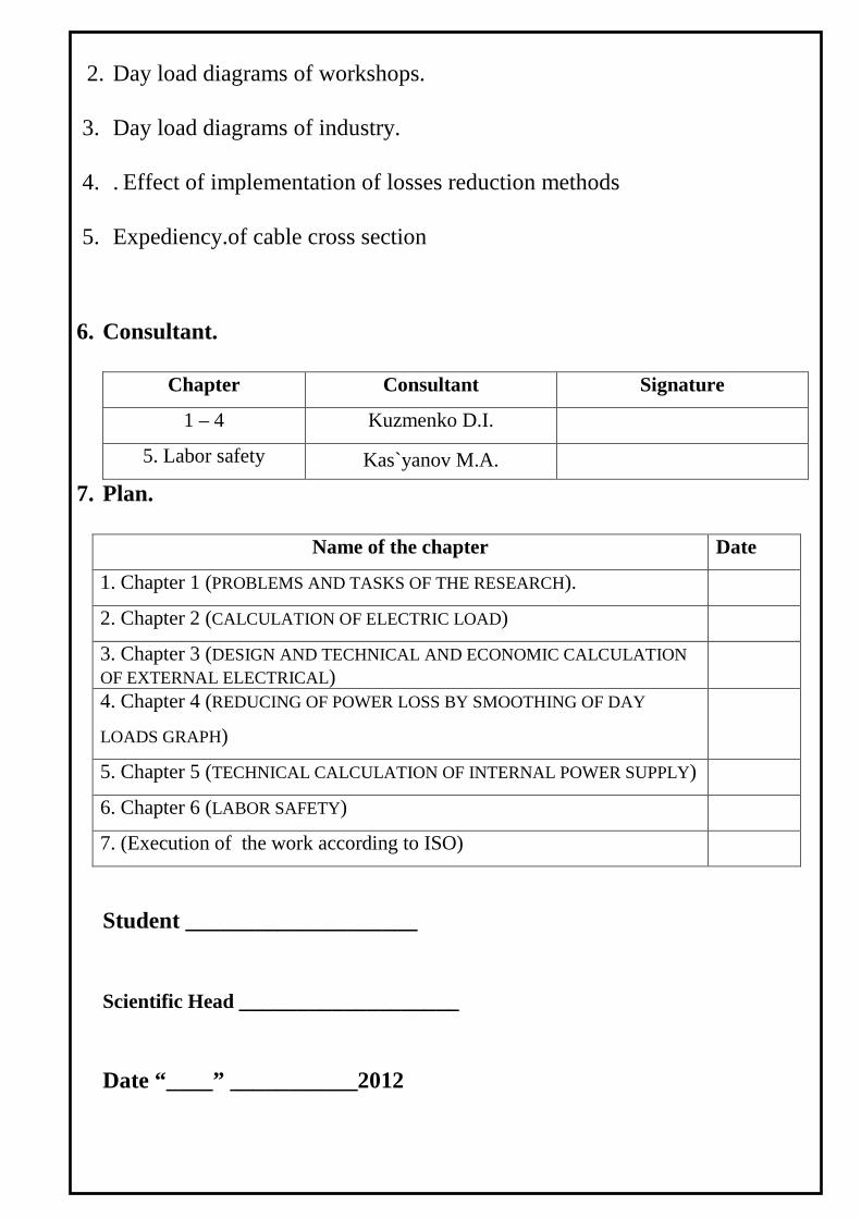
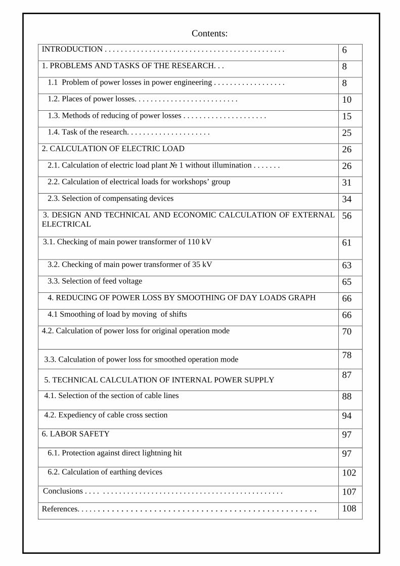
Змн Арк докум Підпис Дата
pag
MT 101101000 EN
1 PROBLEMS AND TASKS OF THE RESEARCH
11 Problem of power losses in power engineering
The issue of limited resources in todays world is one of the most pressing The
constant increase of production which is characteristic for the global industry as the
intensive and extensive way in most cases leads to an increase in power consumption
This creates a shortage of energy resources
The division of natural resources in inexhaustible and exhaustible is becoming
more tentative Many types of resources are now moving from the first into the second
category
The main type of energy is still mineral fuels - oil gas and coal These non-
renewable energy sources and at the present rate of growth of their production they may
be exhausted by 80-140 years However the proportion of these sources must be reduced
through the development of nuclear energy based on the use of heavy fuel - fissile
isotopes of thorium and uranium However these non-renewable resources the scientists
calculations only enough uranium for several decades Also by order of the European
Union the construction of nuclear power is suspended which increases the need for fossil
fuel Energy shortages in turn will significantly increase the cost for exhaustible
resources
At this point the specific consumption of fuel produced at the 1 kWh is 200-
400 g kWh The need for power produced from the power of one million kWh is
11-13 tons per day
Thus the problem of reducing the power loss is becoming increasingly important
for both private and state-owned enterprises
Power losses in electrical networks - a key indicator of efficiency of their work a
clear indicator of the state accounting system of electricity the efficiency of energy sales
of power supply companies
Змн Арк докум Підпис Дата
pag
MT 101101000 EN
This indicator is all the clearer indicates the cumulative problems that require
urgent solutions in development reconstruction and technical re-equipment of electrical
networks methods and means of improving their operation and management to improve
the precision metering of electricity the efficiency of collecting money for the electricity
supplied to consumers etc
According to international experts the relative power losses during transmission
and distribution in networks of most countries can be considered satisfactory if they do not
exceed 4-5 The loss of electricity at 10 can be considered as acceptable from the
standpoint of physics transmission over networks
It is becoming increasingly clear that the aggravation of the problem of reducing
the energy losses in electric networks require an active search for new ways to solve it
new approaches to the selection of appropriate activities and most importantly the
organization works to reduce losses
Due to the sharp decline in investment in the development and modernization of
power grids in the improvement of their management regimes measurement equipment a
number of negative trends affecting the level of losses in the networks such as outdated
equipment physical and moral deterioration of electricity metering discrepancy the
equipment installed transmission capacity
From the aforementioned it follows that on the background of a changing
economic mechanism in the energy sector the economic crisis in the country the problem
of reducing energy losses in electric networks not only has not lost its relevance but
instead popped into one of the tasks of ensuring the financial stability of power supply
companies
Змн Арк докум Підпис Дата
pag
MT 101101000 EN
12 Places of power losses
After electric power is generated it is sent through the transmission linesto the
many distribution circuits that the utility operates The purpose of thedistribution system is
to take that power from the transmission system anddeliver it to the consumers to serve
their needs However a significant portion ofthe power that a utility generates is lost in the
distribution process These lossesoccur in numerous small components in the distribution
system such astransformers and distribution lines Due to the lower power level of
thesecomponents the losses inherent in each component are lower than those
incomparable components of the transmission system While each of thesecomponents
may have relatively small losses the large number of componentsinvolved makes it
important to examine the losses in the distribution systemThese losses typically account
for approximately four percent of the total systemload
There are two major sources of losses in power distribution systemsThese are the
transformers and power lines Additionally there are two majortypes of losses that occur
in these components These losses are often referred toas core losses and copper or
I2Rlosses Core losses in transformers account forthe majority of losses at low power
levels As load increases the copper lossesbecome more significant until they are
approximately equal to the core losses atpeak load
The economic implications of these losses are far reaching In addition tothe
excess fuel cost needed to cover the lost energy added generating capacitymay be needed
Also the power lost in the distribution system must still betransmitted through the
transmission system which further adds to the loss in thatsystem It is very important for
electric power suppliers to consider these lossesand reduce them wherever practical
Losses in Distribution Lines
One of the major sources of losses in the distribution system is the powerlines
which connect the substation to the loads Virtually all real power that islost in the
distribution system is due to copper losses Since these losses are afunction of the square
Змн Арк докум Підпис Дата
pag
MT 101101000 EN
of the current flow through the line it should be obviousthat the losses in distribution lines
are larger at high power levels than they are atlower levels
Since power loss in the distribution lines can be considered to be entirelydue to
copper losses it can be calculated using formula
P=I2R (11)
From this it is apparent that anything that changes either current or lineresistance
will affect the amount of power lost in the line
The primary determining factor for the magnitude of line current is theamount of
real and reactive power loading at the end of the line As the powerthat is transmitted
along the line increases the current flow in the line becomeslarger Another factor which
affects the level of current flow is the operatingvoltage of the line For a given real and
reactive power load level S a highvoltage line will have a lower current than a low
voltage line This can be seenfrom formula
S=UI (12)
Therefore for a given power level the higher voltage line will have lower
copperlosses
Another factor which can result in higher line losses is unbalancedloading If one
of the phases is loaded more heavily than the others the loss willbe larger than it would
have been in the balanced load case This is due to thesquaring of the current in (11) For
instance if one line carries twicethe current of the other two and all other factors are kept
constant an increase incopper loss of 125 occurs compared to the balanced load case
While the current level has the biggest effect on line loss the resistance ofthe line
cannot be neglected The line resistance depends on many factorsincluding the length of
the line the effective cross-sectional area and theresistivity of the metal of which the line
is made The resistance is inverselyproportional to the cross-sectional area and directly
proportional to both thelength and resistivity This is shown in 13 below where R is
Змн Арк докум Підпис Дата
pag
MT 101101000 EN
theresistance ρ is the resistivity L is the length of the line and A is the effectivecross-
sectional area
R=ρLA (13)
Therefore a long line will have a higher resistance and larger losses than a
shortline with the same current flow Similarly a large conductor size results in asmaller
resistance and lower losses than a small conductor
The resistivity is determined by the material of which the line isconstructed and the
temperature of the material A better conducting material willresult in lower resistivity and
lower losses The resistivity of the metal in the linewill be affected by the temperature As
the temperature of the metal increasesthe line resistance will also increase causing higher
copper losses in thedistribution line The resistivity of copper and aluminum can be
calculated from
(14)
Losses in Distribution Transformers
While losses in distribution lines are virtually all due to copper lossestransformer
losses occur due to both copper and core losses The core losses aremade up of eddy
current and hysteresis losses The copper losses in transformersare essentially the same as
those in the power distribution lines
The copper losses in a transformer are smaller in magnitude than the corelosses
These losses occur in the form of heat produced by the current bothprimary and
secondary through the windings of the transformer Like the copperloss in the distribution
line it is calculated using the P=I2Rrelationship of 11 Any factor which affects either
current or winding resistance will alsoaffect the amount of copper loss in the transformer
Змн Арк докум Підпис Дата
pag
MT 101101000 EN
An increase in loading either real or reactive will result in an increase incurrent
flow and a correspondingly greater amount of loss in the transformerAdditionally an
unbalanced system load will increase transformer loss due to thesquared current
relationship The winding resistance also has an effect on theamount of copper loss and is
mainly determined by the total length of the wireused as well as the size of the wire The
temperature of the winding will affectthe resistivity of the wire therefore affecting the
overall resistance and thecopper loss Since all but the smallest distribution transformers
have some typeof cooling system such as immersion in oil the temperature effect on
losses isusually minimal
The core loss in a transformer is usually larger in magnitude than thecopper loss It
is made up of eddy current losses which are due to magneticallyinduced currents in the
core and hysteresis losses which occur because of theless than perfect permeability of the
core material These losses are relativelyconstant for an energized transformer and can be
considered to be independentof the transformer load Transformer core losses have been
modeled in variousways usually as a resistance in parallel with the transformers
magnetizingreactance
Since the core loss is relatively independent of loading the most importantfactor
when considering core loss is the manufacture of the core The physicalconstruction of the
core has serious consequences on the amount of core lossoccurring in the transformer For
instance eddy currents are greatly reduced byusing laminated pieces to construct the core
These thin sheets are oriented alongthe path of travel of the magnetic flux and restrict the
amount of induced currentsthat occur
The hysteresis loss occurs in the transformer core due to the energyrequired to
provide the magnetic field in the core as the direction of magneticflux alternates with the
alternating current wave form This energy is transformedinto heat Hysteresis loss can be
reduced by the use of higher quality materials inthe core which have better magnetic
permeability Many advanced core materialshave been developed recently with claims of
core loss reductions in the range of50 and above
Змн Арк докум Підпис Дата
pag
MT 101101000 EN
A final aspect of the distribution system that increases losses in thetransformers is
the presence of harmonics in the system The harmonic currentsonly cause a small increase
in copper losses throughout the system However thehigh frequency harmonic voltages
can cause large core losses in the transformerFrequently utilities are forced to use an
oversized transformer to compensatewhen a large harmonic presence is indicated The
increased skin effect of largerconductors combined with the high frequency harmonics can
result in evengreater losses
Losses due to nonoptimal modes of electrical networks the errors of measurement
equipment deficiencies in the power sales activities are the direct loss of power supply
organizations and of course must be reduced
Therefore normative power losses of industrial enterprises can be divided into quasi-
constant and loading
Quasi-constant losses
- on the crown
- in steel of transformers
- in compensating devices
- in the accounting system
- in the valve and surge arresters
- in the cable insulation
- from the leakage of overhead insulators
- own demands of substations
- melting ice
Loading losses
- in line
- in transformers
- in current-limiting reactors
Змн Арк докум Підпис Дата
pag
MT 101101000 EN
Excessive losses include
- low level of reactive power compensation
- nonoptimal operation of networks due to overload and underload equipment
- poor technical condition equipment
- outdated equipment with high power consumption
- inefficient networking
13 Methods of reducing of power losses
According to international experts the relative power losses during transmission
and distribution in networks of most countries can be considered satisfactory if they do not
exceed 4-5 The loss of electricity at 10 can be considered as acceptable from the
standpoint of physics transmission over networks This is confirmed by the pre-crisis level
of energy losses in most of the power of the former Soviet Union which does not exceed
usually 10 Since today the rates are increased by 15-2 and the electric grid for
individual companies - even three times it is obvious that in the context of the economic
mechanism of change in energy economic crisis in the country the problem of reducing
energy losses in electric networks not only lost its relevance and vice versa - has popped
into one of the tasks of ensuring the financial stability of organizations
Technical
- Optimization of the power networks load due to construction of transmission
lines and substations
- Replacement of overloaded and underloaded power networks equipment
- Commissioning of electric energy saving equipment
Змн Арк докум Підпис Дата
pag
MT 101101000 EN
Organizational
- Optimization of circuits and modes of supply
- Reduction of electrical systems repairs
- Commissioning of unused auto-regulation of load equalization of asymmetric
loads phase and so on
Measures to improve the design of systems and technical accounting of energy
- Conducting raids to identify unrecorded electricity
- Improving the system for collecting indications of counters
- To ensure normal working conditions of metering devices
- The replacement modernization installation of the missing meters
Compensating of reactive power
In electrical circuits with a purely resistive load flowing current is not leading and
lagging the voltage Inductive load current lags the voltage the capacitance leads voltage
At work electric motors compressors electromagnets etc that the most typical of most
consumer load is inductive and the total power consumption of reactive power is present
In this case the power factor is reduced and its increasing need to connect a capacitive
load which compensates for the inductive component The resulting load is closer to a
purely active power factor and takes the maximum value For reactive power
compensation condenser units are used in the automatic mode increasing the power factor
and thereby reduce the overall losses of the consumer In particular with an increase in the
power factor from 05 to 09 reactive power is reduced by 44
The need for energy conservation is becoming increasingly important This is due
to the increasing deficit and increasing energy costs growth of production and urban
infrastructure The majority of consumers consume along with active power and reactive
power which is spent on the creation of electromagnetic fields and is useless The
presence of reactive power supply reduces the quality of electricity leads to an increase in
Змн Арк докум Підпис Дата
pag
MT 101101000 EN
charges for electricity additional losses and overheating of wires overloaded substations
need to over-capacity power transformers and cable cross-sections subsidence voltage
sources
The use of condensing units allows to reduce the amount of reactive power
consumption and achieve economic benefits in terms of energy savings
There are several ways to reduce reactive power but the use for these purposes is
condensing units is preferred Condensing units have low loss ease of setup and operation
they can be plugged into any power point They can be used to compensate for almost any
amount of reactive power The payback period condensing units is less than years and in
some cases no more than several months
In the future we should expect a further increase of tariffs on the consumption of
reactive power
Implementation of condensing units will help to avoid subsidence voltage on
power lines of remote users will reduce the amount of payment for electricity to ensure
power supply cable with a smaller cross-section increase the service life of electrical
equipment due to its lower heat
What consumers need power factor correction
Reactive power compensation is particularly important for consumers who have a
low coefficient of power In particular this applies to customers operated with a large
number of induction motors (power factor ~ 07) especially in view of underloading
(power factor ~ 05) lifting and transport mechanisms (power factor ~ 05)
In place of the connection distinguish following schemes of reactive power
compensation
total - on input the enterprise
group - on the power line of the same type of consumers
Individual - condenser unit is installed in close proximity to the consumer with a
low cosine fi
Individual compensation scheme is most preferred It allows you to compensate the
reactive power in the place of its occurrence without causing overflow of reactive power
Змн Арк докум Підпис Дата
pag
MT 101101000 EN
in power lines and in the case of the immutability of the power factor the consumer to
fully compensate the reactive power by using a constant capacitance of the capacitor unit
However an individual compensation scheme is not always applicable As a rule at
the enterprise operated a lot of electrical power with low and provide them with all the
individual capacitor banks is not possible Also the persistent power factor in life are rare
most often the level of reactive power depends on the mode of operation of electrical and
varies during the day
Therefore a mixed use scheme of compensation when the reactive power of the
largest consumers partially offset by individual capacitor bank fixed capacitors and
variable balance of reactive power and reactive power is compensated by smaller
customers with automated capacitor bank connected on input of the enterprise
Types of condenser units
As a switching element in the condenser units can be used contactors or
thyristors Contactor capacitor banks were the most widely used because of easier
implementation and lower cost compared to the thyristor (static) condenser units
However if the load is quick-changing character for reactive power compensation applied
thyristor capacitor banks as they have the highest speed And the fact that the thyristor
switched capacitors in the capacitor units occurs at zero current greatly extends the life of
a capacitor bank and the entire installation
In addition there are specific installation of reactive power compensation not
containing capacitors in which the phase shift between current and voltage compensated
with current generators built on the non-linear elements of either synchronous generators
but they have not achieved widespread use because of the complexity and the technical
realization of their high cost
Voltage capacitor banks are divided into low voltage (04 kV) and high (63 10
kV or more)
Змн Арк докум Підпис Дата
pag
MT 101101000 EN
The influence of higher harmonics on life of condensing units
In todays networks due to the nonlinearity of the electrical load (for example in
pulsed operation of stabilizers and power converters) having the higher current harmonics
which in magnitude are often commensurate with the fundamental harmonic Cosine
capacitors for reactive power compensation systems in conjunction with the inductance of
the load can form a tuned circuit close to the resonance frequency to the frequency of one
of the higher harmonics This leads to a significant increase in power capacitors and
significantly shortens their life span Overvoltages occurring at resonance on the elements
of the capacitor bank and the load can lead to breakdown of insulation To address these
issues during site survey before the introduction of condensing units for reactive power
compensation is necessary to analyze the spectrum of current consumption To suppress
the used filter-plugs tuned to the frequency of the most significant harmonics
In developing the balance of power in the electrical network must be compiled
balance the active and reactive power of network to their consumption including losses in
the network was provided by the generation of the active and reactive power on the power
system the transfer of power from neighboring and other sources of reactive power At the
same time should be provided with a reserve in case of disaster or in a repair mode
In assessing the consumption of reactive power used the power factor
cos φ = P S
where P S - respectively the values of the active and apparent power
The power factor is insufficient characteristic of reactive power consumption since
the values of cos φ close to 1 the power consumption of the reactive power is still quite
high For example at high value of cos φ = 095 reactive power load consumption is 33
consumed by active power (Table 1) At cos φ = 07 the value of consumption reactive
power is almost equal to the active power
The most successful indicator of the amount of consumption of the reactive power
is the ratio of
tg φ = QP
where Q P - respectively the values of reactive power and active power
Змн Арк докум Підпис Дата
pag
MT 101101000 EN
The transfer of the reactive power to the consumer and its consumption in the
network lead to additional losses in the active power power distribution networks In
Table 16 shows an example of calculating the consumer utility of active power
transmission over the network constant active power (P = 100) at different cos φ and
condition that the transfer of this amount of power loss in the active power of network
when cos φ = 1 are equal to ΔP = 10 Loss of AM in the electrical network
∆119875119875 = 1198751198752+1198761198762
1198801198802 119877119877 = 1198751198752(1+1199051199051199051199052120593120593)1198801198802 119877119877 = 1198751198752119877119877
1198801198802 ∙1
119888119888119888119888119888119888 2120593120593 (15)
where where P Q U - respectively the active power reactive power and the
supply voltage
R - the equivalent resistance of the network
tg φ - reactive power coefficient of the network
cos φ - power factor in the network
From the expression it follows that at constant parameters of the transmitted power
(P) voltage (U) and the resistance of the network (R) value of the losses of network active
power is inversely proportional to the square of the power factor of transmitted or
∆119875119875 = 119891119891 ∙ 1119888119888119888119888119888119888 2120593120593
(16)
Using this relationship in table 16 determined the values of the active losses in
the network at different cos and unchanged AM transferred over the network From the
calculations in table 16 shows that the loss of active power in the electrical network are
growing rapidly with decreasing of cos φ If cos φ = 05 they reach 40 and at cos φ =
0316 entire active power transmitted over the network is spent on losing it The value of
reactive power is almost 3 times higher than of active power
In the electricity supply network RSK RAO UES of Russia in 2007 amounted to
7425 billion kilowatt-hours Of this amount of electricity through the network 10 (6) -04
kV released 50 of electricity or 370 billion kWh Electricity losses in networks of 10 (6)
-04 kV RAC assessment in 2007 was 116
∆11988211988211989111989111989111989111988811988811990511990510(6)minus04 = 370 ∙ 0116 asymp 43 ∙ 109119896119896119882119882 ∙ ℎ
Змн Арк докум Підпис Дата
pag
MT 101101000 EN
We assume that due to the measures to optimize the balance of the reactive power
of network cos φ is increased by 001 Then the projected loss of power reduced to a value
of
∆11988211988211989111989111988811988811989111989111989111989111988811988811989111989111988811988811990511990510(6)minus04 = 43 ∙ 109 0852
0862 asymp 42 ∙ 109119896119896119882119882 ∙ ℎ
Consequently we can tentatively assume that the increase in the overall power
factor in electric networks 10 (6) -04 kV RAC 001 (12) will save 1 billion kWh of
electricity at an average cost of a kWh at the wholesale electricity market in Russia in
2007 at a rate of 068 rubles will make annual savings of 680 million rubles or more than
28 million US dollars per year This does not exhaust the economic importance of
improving the power factor
Increasing the power factor of 001 in the networks of 10 (6) -04 kV SSC releases
power generators to power about 150 thousand kW If we consider that for the production
of 11 billion kWh of electricity should be about 0370 million tons of standard fuel which
must be obtained from the bowels of the earth to spend a great work on the production
and delivery to the plant providing electricity generation we can provide all the economic
benefits in the economy from reduced consumption of reactive power Increased
consumption of reactive power from the network at low values of cos φ calls for increased
cross-sections of wires and cables in power networks in order to reduce losses If cos φ 07
overruns caused by non-ferrous metals (copper and aluminum) will be more than 50
Low cos φ leads to excessive load of reactive power transmission in step-down
substations so needs of increasing the power of transformers or their number Increased
network load reactive current causes a drop voltage and sharp fluctuations in the value of
the reactive power - fluctuations in voltage and consequently the deterioration of the
quality of electricity allocated by consumers
Змн Арк докум Підпис Дата
pag
MT 101101000 EN
Table 11
Value of reactive power in dependence on cos φ
(in percentage of active power) cosφ 10 099 097 095 094 092 09 087 085 08 07 05 0316
tgφ 0 014 025 033 036 043 0484 055 06 075 102 173 3016
Q 0 14 25 33 36 43 484 55 60 75 102 173 3016
Table 12
Value of active losses with different cos φ and constant active power
transferred in the network
cosφ tgφ Power Active losses
ΔP=10cos2φ
Useful active power of user
(P- ΔP) in of P Reactive Q=P tgφ Total S=Pcosφ
1 0 0 100 10 90 09 0484 484 1111 123 877 08 075 75 125 156 844 07 102 102 1429 204 796 05 173 1732 200 40 60
0316 3016 3016 3165 -100 0
At present the nature of public utilities load has changed dramatically as a result
of the wide spread of new types of power consumers (microwave ovens air conditioners
freezers fluorescent lamps washing machines and dishwashers personal computers etc)
consuming from the feed network along with active power also a significant reactive
power As early as 1987 the Ministry of Energy and Electrification of the USSR [9]
established the extent of compensation of reactive power in the amount of cos φ = 0858
(tg φ = 06) At the same time on different expert estimates the power factor in
distribution networks has a value of about 08-085 (tg φ = 075-062)
In 2007 in Russia requirement for the minimum value of the coefficient of the
reactive power for the consumer connection points to the power supply 10 (6) -04 kV was
considerably stiffened and set cos φ = 0944 (tg φ = 035) for network 04 kV and cos φ =
093 (tg φ = 04) for a network of 6-20 kV
Змн Арк докум Підпис Дата
pag
MT 101101000 EN
As is known the use of compensation can significantly improve the technical and
economic performance of power distribution networks with a voltage of 10 (6) -04 kV
due to
1) reducing the loss of active power
2) increasing the capacity of step-down transformer 10 (6) 04 kV
To estimate the degree of reduction of losses of active power assume that N
transformer substations 10 (6) 04 kV (TS) with the rated capacity of Sn (kW) powered
by a radial scheme from the power supply unit (FS) The transformers are equally loaded
with capacity S with the power factor cos φ Cable (air) line at full compensation on the
side of 04 kV the AM loss of Ts in the distribution network will be equal (neglecting
losses of reactive power in transformers 10 (6) 04 kV)
∆119875119875119897119897prime = 119873119873 ∙ (1198751198752 ∙ 1198771198770119891119891119886119886 ∙ 119871119871119898119898119898119898119898119898 ∙ 10minus3)1198801198801198991198992 kW (17)
Losses of active power during the actual loading S (in the absence of
compensation)
∆119875119875119897119897 = 119873119873 ∙ (1198781198782 ∙ 1198771198770119891119891119886119886 ∙ 119871119871119898119898119898119898119898119898 ∙ 10minus3)1198801198801198991198992 kW (18)
where Roav - the average value of specific resistance of supply lines from the FS
to the TS Ohm km Lav - the average length of supply lines from the FS to the TS km
Un-rated voltage of the electrical network kV
The ratio values of these losses can be characterized by the appropriate factor
119870119870119888119888 = ∆119875119875119897119897∆119875119875119897119897
prime = 1198781198782
1198751198752 = 1119888119888119888119888119888119888 2120593120593
(19)
The lower the value of the previous power factor the higher the efficiency of
compensation
Considering that the actual power factor in power distribution networks 10(6) -
04 kV is about 08-085 it is easy to see that the loss of active power in the distribution
network after installing condenser units can be reduced to 138-156 times or 27-36
Змн Арк докум Підпис Дата
pag
MT 101101000 EN
Table 13
Dependence of compensation on power factor in cable and overhead lines
cos φ 08 085 09 095 10
Kc 1563 1384 1235 1108 10
Losses in transformers AM are characterized by a complex dependence compared
to the power lines
∆119875119875119905119905119891119891 = 119873119873 ∙ (∆119875119875119899119899119897119897 + 1205731205732 ∙ ∆119875119875119888119888119888119888) (110)
where 119875119875119899119899119897119897 is no-load losses kW ∆119875119875119888119888119888119888 is short circuit losses kW 120573120573 = 119878119878119878119878119899119899 is ratio
of loading of transformer by total power
With full compensation on 04 kV losses of active power will reduce and would be
equal
∆119875119875prime119905119905119891119891 = 119873119873 ∙ (∆119875119875119899119899119897119897 + 1205721205722 ∙ ∆119875119875119888119888119888119888) (111)
where α= 119875119875119878119878119899119899 is ratio of loading of transformer by active power
The ratio values of these losses can be calculated from following formula
119870119870119888119888 = 119873119873∙(∆119875119875119899119899119897119897 +1205731205732∙∆119875119875119888119888119888119888)119873119873∙(∆119875119875119899119899119897119897 +1205721205722∙∆119875119875119888119888119888119888)
= (1+1205731205732∙∆119875119875119888119888119888119888∆119875119875119899119899119897119897 )1+1205721205722∙∆119875119875119888119888119888119888∆119875119875119899119899119897119897
(112)
In the particular case with load of transformer on nominal capacity will have β=1
α=PSn= cos φ Then the last expression can be put in the form
119870119870119888119888 = (1+119870119870119891119891)(1+119870119870119891119891∙119888119888119888119888119888119888 2120593120593)
(113)
where Kr =∆119875119875119888119888119888119888∆119875119875119899119899119897119897
= 60 is the coefficient characterizing the ratio of losses of short
circuit to the losses of no-load in transformers with capacity of 400-1000 kVA
Analysis of the data presented in Table 4 shows that due to no-load losses which
do not depend on the load the degree of reduction of losses in transformers AM when
installing BC will be somewhat less than in the cable or overhead lines Thus the loss of
AM in the step-down transformer 10 (6) 04 kV after installing BC can be reduced to
131-144 times or 24-31
Змн Арк докум Підпис Дата
pag
MT 101101000 EN
Table 14
Dependence of compensation on power factor in step-down transformers
cos φ 08 085 09 095 10
Kc 1446 1312 1195 1091 10
The calculations show that the main effect in reducing the technical losses of
electricity can be produced by modernization renovation improving throughput and
reliability of electrical networks a balance of modes ie through the introduction of
capital-intensive activities
The priority actions to reduce technical losses in electricity distribution networks
04-35 kV are
- the use of 10 kV as the primary voltage distribution network
- increase in the proportion of networks with a voltage of 35 kV
- reduction in range and construction of overhead lines (04 kV) in the three-
phase over the entire length
- the use of self-supporting insulated and protected wires for voltage 04-10 kV
overhead line
- using the maximum allowable cross section wires in the electrical voltage of
04-10 kV networks in order to adapt their carrying capacity to increase load
during the entire period of service
- development and introduction of new more cost-effective electrical
equipment such as distribution transformers with reduced active and reactive
losses idling and embedded in the CTS and ITS capacitor banks
- the use of low power transformers pillar (6-100 4 kV) to reduce the length of
the network voltage of 04 kV and the energy losses in them
- greater use of the automatic voltage regulation under load booster transformers
voltage regulation of the local to improve power quality and reduce its losses
Змн Арк докум Підпис Дата
pag
MT 101101000 EN
- complex automation and telemechanization electrical networks the use of
switching devices of new generation of remote fault location in networks to
reduce the duration of nonoptimal repair and post-emergency modes search
and emergency response
- improving the reliability of measurements in networks using new information
technologies automation processing telemetry data
14 Task of the research
- Calculation and selection of main power supply elements of industry
- Analysis of implementation of methods of power loss reduction

Змн Арк докум Підпис Дата
pag
MT 101101000 EN
of the current flow through the line it should be obviousthat the losses in distribution lines
are larger at high power levels than they are atlower levels
Since power loss in the distribution lines can be considered to be entirelydue to
copper losses it can be calculated using formula
P=I2R (11)
From this it is apparent that anything that changes either current or lineresistance
will affect the amount of power lost in the line
The primary determining factor for the magnitude of line current is theamount of
real and reactive power loading at the end of the line As the powerthat is transmitted
along the line increases the current flow in the line becomeslarger Another factor which
affects the level of current flow is the operatingvoltage of the line For a given real and
reactive power load level S a highvoltage line will have a lower current than a low
voltage line This can be seenfrom formula
S=UI (12)
Therefore for a given power level the higher voltage line will have lower
copperlosses
Another factor which can result in higher line losses is unbalancedloading If one
of the phases is loaded more heavily than the others the loss willbe larger than it would
have been in the balanced load case This is due to thesquaring of the current in (11) For
instance if one line carries twicethe current of the other two and all other factors are kept
constant an increase incopper loss of 125 occurs compared to the balanced load case
While the current level has the biggest effect on line loss the resistance ofthe line
cannot be neglected The line resistance depends on many factorsincluding the length of
the line the effective cross-sectional area and theresistivity of the metal of which the line
is made The resistance is inverselyproportional to the cross-sectional area and directly
proportional to both thelength and resistivity This is shown in 13 below where R is
Змн Арк докум Підпис Дата
pag
MT 101101000 EN
theresistance ρ is the resistivity L is the length of the line and A is the effectivecross-
sectional area
R=ρLA (13)
Therefore a long line will have a higher resistance and larger losses than a
shortline with the same current flow Similarly a large conductor size results in asmaller
resistance and lower losses than a small conductor
The resistivity is determined by the material of which the line isconstructed and the
temperature of the material A better conducting material willresult in lower resistivity and
lower losses The resistivity of the metal in the linewill be affected by the temperature As
the temperature of the metal increasesthe line resistance will also increase causing higher
copper losses in thedistribution line The resistivity of copper and aluminum can be
calculated from
(14)
Losses in Distribution Transformers
While losses in distribution lines are virtually all due to copper lossestransformer
losses occur due to both copper and core losses The core losses aremade up of eddy
current and hysteresis losses The copper losses in transformersare essentially the same as
those in the power distribution lines
The copper losses in a transformer are smaller in magnitude than the corelosses
These losses occur in the form of heat produced by the current bothprimary and
secondary through the windings of the transformer Like the copperloss in the distribution
line it is calculated using the P=I2Rrelationship of 11 Any factor which affects either
current or winding resistance will alsoaffect the amount of copper loss in the transformer
Змн Арк докум Підпис Дата
pag
MT 101101000 EN
An increase in loading either real or reactive will result in an increase incurrent
flow and a correspondingly greater amount of loss in the transformerAdditionally an
unbalanced system load will increase transformer loss due to thesquared current
relationship The winding resistance also has an effect on theamount of copper loss and is
mainly determined by the total length of the wireused as well as the size of the wire The
temperature of the winding will affectthe resistivity of the wire therefore affecting the
overall resistance and thecopper loss Since all but the smallest distribution transformers
have some typeof cooling system such as immersion in oil the temperature effect on
losses isusually minimal
The core loss in a transformer is usually larger in magnitude than thecopper loss It
is made up of eddy current losses which are due to magneticallyinduced currents in the
core and hysteresis losses which occur because of theless than perfect permeability of the
core material These losses are relativelyconstant for an energized transformer and can be
considered to be independentof the transformer load Transformer core losses have been
modeled in variousways usually as a resistance in parallel with the transformers
magnetizingreactance
Since the core loss is relatively independent of loading the most importantfactor
when considering core loss is the manufacture of the core The physicalconstruction of the
core has serious consequences on the amount of core lossoccurring in the transformer For
instance eddy currents are greatly reduced byusing laminated pieces to construct the core
These thin sheets are oriented alongthe path of travel of the magnetic flux and restrict the
amount of induced currentsthat occur
The hysteresis loss occurs in the transformer core due to the energyrequired to
provide the magnetic field in the core as the direction of magneticflux alternates with the
alternating current wave form This energy is transformedinto heat Hysteresis loss can be
reduced by the use of higher quality materials inthe core which have better magnetic
permeability Many advanced core materialshave been developed recently with claims of
core loss reductions in the range of50 and above
Змн Арк докум Підпис Дата
pag
MT 101101000 EN
A final aspect of the distribution system that increases losses in thetransformers is
the presence of harmonics in the system The harmonic currentsonly cause a small increase
in copper losses throughout the system However thehigh frequency harmonic voltages
can cause large core losses in the transformerFrequently utilities are forced to use an
oversized transformer to compensatewhen a large harmonic presence is indicated The
increased skin effect of largerconductors combined with the high frequency harmonics can
result in evengreater losses
Losses due to nonoptimal modes of electrical networks the errors of measurement
equipment deficiencies in the power sales activities are the direct loss of power supply
organizations and of course must be reduced
Therefore normative power losses of industrial enterprises can be divided into quasi-
constant and loading
Quasi-constant losses
- on the crown
- in steel of transformers
- in compensating devices
- in the accounting system
- in the valve and surge arresters
- in the cable insulation
- from the leakage of overhead insulators
- own demands of substations
- melting ice
Loading losses
- in line
- in transformers
- in current-limiting reactors
Змн Арк докум Підпис Дата
pag
MT 101101000 EN
Excessive losses include
- low level of reactive power compensation
- nonoptimal operation of networks due to overload and underload equipment
- poor technical condition equipment
- outdated equipment with high power consumption
- inefficient networking
13 Methods of reducing of power losses
According to international experts the relative power losses during transmission
and distribution in networks of most countries can be considered satisfactory if they do not
exceed 4-5 The loss of electricity at 10 can be considered as acceptable from the
standpoint of physics transmission over networks This is confirmed by the pre-crisis level
of energy losses in most of the power of the former Soviet Union which does not exceed
usually 10 Since today the rates are increased by 15-2 and the electric grid for
individual companies - even three times it is obvious that in the context of the economic
mechanism of change in energy economic crisis in the country the problem of reducing
energy losses in electric networks not only lost its relevance and vice versa - has popped
into one of the tasks of ensuring the financial stability of organizations
Technical
- Optimization of the power networks load due to construction of transmission
lines and substations
- Replacement of overloaded and underloaded power networks equipment
- Commissioning of electric energy saving equipment
Змн Арк докум Підпис Дата
pag
MT 101101000 EN
Organizational
- Optimization of circuits and modes of supply
- Reduction of electrical systems repairs
- Commissioning of unused auto-regulation of load equalization of asymmetric
loads phase and so on
Measures to improve the design of systems and technical accounting of energy
- Conducting raids to identify unrecorded electricity
- Improving the system for collecting indications of counters
- To ensure normal working conditions of metering devices
- The replacement modernization installation of the missing meters
Compensating of reactive power
In electrical circuits with a purely resistive load flowing current is not leading and
lagging the voltage Inductive load current lags the voltage the capacitance leads voltage
At work electric motors compressors electromagnets etc that the most typical of most
consumer load is inductive and the total power consumption of reactive power is present
In this case the power factor is reduced and its increasing need to connect a capacitive
load which compensates for the inductive component The resulting load is closer to a
purely active power factor and takes the maximum value For reactive power
compensation condenser units are used in the automatic mode increasing the power factor
and thereby reduce the overall losses of the consumer In particular with an increase in the
power factor from 05 to 09 reactive power is reduced by 44
The need for energy conservation is becoming increasingly important This is due
to the increasing deficit and increasing energy costs growth of production and urban
infrastructure The majority of consumers consume along with active power and reactive
power which is spent on the creation of electromagnetic fields and is useless The
presence of reactive power supply reduces the quality of electricity leads to an increase in
Змн Арк докум Підпис Дата
pag
MT 101101000 EN
charges for electricity additional losses and overheating of wires overloaded substations
need to over-capacity power transformers and cable cross-sections subsidence voltage
sources
The use of condensing units allows to reduce the amount of reactive power
consumption and achieve economic benefits in terms of energy savings
There are several ways to reduce reactive power but the use for these purposes is
condensing units is preferred Condensing units have low loss ease of setup and operation
they can be plugged into any power point They can be used to compensate for almost any
amount of reactive power The payback period condensing units is less than years and in
some cases no more than several months
In the future we should expect a further increase of tariffs on the consumption of
reactive power
Implementation of condensing units will help to avoid subsidence voltage on
power lines of remote users will reduce the amount of payment for electricity to ensure
power supply cable with a smaller cross-section increase the service life of electrical
equipment due to its lower heat
What consumers need power factor correction
Reactive power compensation is particularly important for consumers who have a
low coefficient of power In particular this applies to customers operated with a large
number of induction motors (power factor ~ 07) especially in view of underloading
(power factor ~ 05) lifting and transport mechanisms (power factor ~ 05)
In place of the connection distinguish following schemes of reactive power
compensation
total - on input the enterprise
group - on the power line of the same type of consumers
Individual - condenser unit is installed in close proximity to the consumer with a
low cosine fi
Individual compensation scheme is most preferred It allows you to compensate the
reactive power in the place of its occurrence without causing overflow of reactive power
Змн Арк докум Підпис Дата
pag
MT 101101000 EN
in power lines and in the case of the immutability of the power factor the consumer to
fully compensate the reactive power by using a constant capacitance of the capacitor unit
However an individual compensation scheme is not always applicable As a rule at
the enterprise operated a lot of electrical power with low and provide them with all the
individual capacitor banks is not possible Also the persistent power factor in life are rare
most often the level of reactive power depends on the mode of operation of electrical and
varies during the day
Therefore a mixed use scheme of compensation when the reactive power of the
largest consumers partially offset by individual capacitor bank fixed capacitors and
variable balance of reactive power and reactive power is compensated by smaller
customers with automated capacitor bank connected on input of the enterprise
Types of condenser units
As a switching element in the condenser units can be used contactors or
thyristors Contactor capacitor banks were the most widely used because of easier
implementation and lower cost compared to the thyristor (static) condenser units
However if the load is quick-changing character for reactive power compensation applied
thyristor capacitor banks as they have the highest speed And the fact that the thyristor
switched capacitors in the capacitor units occurs at zero current greatly extends the life of
a capacitor bank and the entire installation
In addition there are specific installation of reactive power compensation not
containing capacitors in which the phase shift between current and voltage compensated
with current generators built on the non-linear elements of either synchronous generators
but they have not achieved widespread use because of the complexity and the technical
realization of their high cost
Voltage capacitor banks are divided into low voltage (04 kV) and high (63 10
kV or more)
Змн Арк докум Підпис Дата
pag
MT 101101000 EN
The influence of higher harmonics on life of condensing units
In todays networks due to the nonlinearity of the electrical load (for example in
pulsed operation of stabilizers and power converters) having the higher current harmonics
which in magnitude are often commensurate with the fundamental harmonic Cosine
capacitors for reactive power compensation systems in conjunction with the inductance of
the load can form a tuned circuit close to the resonance frequency to the frequency of one
of the higher harmonics This leads to a significant increase in power capacitors and
significantly shortens their life span Overvoltages occurring at resonance on the elements
of the capacitor bank and the load can lead to breakdown of insulation To address these
issues during site survey before the introduction of condensing units for reactive power
compensation is necessary to analyze the spectrum of current consumption To suppress
the used filter-plugs tuned to the frequency of the most significant harmonics
In developing the balance of power in the electrical network must be compiled
balance the active and reactive power of network to their consumption including losses in
the network was provided by the generation of the active and reactive power on the power
system the transfer of power from neighboring and other sources of reactive power At the
same time should be provided with a reserve in case of disaster or in a repair mode
In assessing the consumption of reactive power used the power factor
cos φ = P S
where P S - respectively the values of the active and apparent power
The power factor is insufficient characteristic of reactive power consumption since
the values of cos φ close to 1 the power consumption of the reactive power is still quite
high For example at high value of cos φ = 095 reactive power load consumption is 33
consumed by active power (Table 1) At cos φ = 07 the value of consumption reactive
power is almost equal to the active power
The most successful indicator of the amount of consumption of the reactive power
is the ratio of
tg φ = QP
where Q P - respectively the values of reactive power and active power
Змн Арк докум Підпис Дата
pag
MT 101101000 EN
The transfer of the reactive power to the consumer and its consumption in the
network lead to additional losses in the active power power distribution networks In
Table 16 shows an example of calculating the consumer utility of active power
transmission over the network constant active power (P = 100) at different cos φ and
condition that the transfer of this amount of power loss in the active power of network
when cos φ = 1 are equal to ΔP = 10 Loss of AM in the electrical network
∆119875119875 = 1198751198752+1198761198762
1198801198802 119877119877 = 1198751198752(1+1199051199051199051199052120593120593)1198801198802 119877119877 = 1198751198752119877119877
1198801198802 ∙1
119888119888119888119888119888119888 2120593120593 (15)
where where P Q U - respectively the active power reactive power and the
supply voltage
R - the equivalent resistance of the network
tg φ - reactive power coefficient of the network
cos φ - power factor in the network
From the expression it follows that at constant parameters of the transmitted power
(P) voltage (U) and the resistance of the network (R) value of the losses of network active
power is inversely proportional to the square of the power factor of transmitted or
∆119875119875 = 119891119891 ∙ 1119888119888119888119888119888119888 2120593120593
(16)
Using this relationship in table 16 determined the values of the active losses in
the network at different cos and unchanged AM transferred over the network From the
calculations in table 16 shows that the loss of active power in the electrical network are
growing rapidly with decreasing of cos φ If cos φ = 05 they reach 40 and at cos φ =
0316 entire active power transmitted over the network is spent on losing it The value of
reactive power is almost 3 times higher than of active power
In the electricity supply network RSK RAO UES of Russia in 2007 amounted to
7425 billion kilowatt-hours Of this amount of electricity through the network 10 (6) -04
kV released 50 of electricity or 370 billion kWh Electricity losses in networks of 10 (6)
-04 kV RAC assessment in 2007 was 116
∆11988211988211989111989111989111989111988811988811990511990510(6)minus04 = 370 ∙ 0116 asymp 43 ∙ 109119896119896119882119882 ∙ ℎ
Змн Арк докум Підпис Дата
pag
MT 101101000 EN
We assume that due to the measures to optimize the balance of the reactive power
of network cos φ is increased by 001 Then the projected loss of power reduced to a value
of
∆11988211988211989111989111988811988811989111989111989111989111988811988811989111989111988811988811990511990510(6)minus04 = 43 ∙ 109 0852
0862 asymp 42 ∙ 109119896119896119882119882 ∙ ℎ
Consequently we can tentatively assume that the increase in the overall power
factor in electric networks 10 (6) -04 kV RAC 001 (12) will save 1 billion kWh of
electricity at an average cost of a kWh at the wholesale electricity market in Russia in
2007 at a rate of 068 rubles will make annual savings of 680 million rubles or more than
28 million US dollars per year This does not exhaust the economic importance of
improving the power factor
Increasing the power factor of 001 in the networks of 10 (6) -04 kV SSC releases
power generators to power about 150 thousand kW If we consider that for the production
of 11 billion kWh of electricity should be about 0370 million tons of standard fuel which
must be obtained from the bowels of the earth to spend a great work on the production
and delivery to the plant providing electricity generation we can provide all the economic
benefits in the economy from reduced consumption of reactive power Increased
consumption of reactive power from the network at low values of cos φ calls for increased
cross-sections of wires and cables in power networks in order to reduce losses If cos φ 07
overruns caused by non-ferrous metals (copper and aluminum) will be more than 50
Low cos φ leads to excessive load of reactive power transmission in step-down
substations so needs of increasing the power of transformers or their number Increased
network load reactive current causes a drop voltage and sharp fluctuations in the value of
the reactive power - fluctuations in voltage and consequently the deterioration of the
quality of electricity allocated by consumers
Змн Арк докум Підпис Дата
pag
MT 101101000 EN
Table 11
Value of reactive power in dependence on cos φ
(in percentage of active power) cosφ 10 099 097 095 094 092 09 087 085 08 07 05 0316
tgφ 0 014 025 033 036 043 0484 055 06 075 102 173 3016
Q 0 14 25 33 36 43 484 55 60 75 102 173 3016
Table 12
Value of active losses with different cos φ and constant active power
transferred in the network
cosφ tgφ Power Active losses
ΔP=10cos2φ
Useful active power of user
(P- ΔP) in of P Reactive Q=P tgφ Total S=Pcosφ
1 0 0 100 10 90 09 0484 484 1111 123 877 08 075 75 125 156 844 07 102 102 1429 204 796 05 173 1732 200 40 60
0316 3016 3016 3165 -100 0
At present the nature of public utilities load has changed dramatically as a result
of the wide spread of new types of power consumers (microwave ovens air conditioners
freezers fluorescent lamps washing machines and dishwashers personal computers etc)
consuming from the feed network along with active power also a significant reactive
power As early as 1987 the Ministry of Energy and Electrification of the USSR [9]
established the extent of compensation of reactive power in the amount of cos φ = 0858
(tg φ = 06) At the same time on different expert estimates the power factor in
distribution networks has a value of about 08-085 (tg φ = 075-062)
In 2007 in Russia requirement for the minimum value of the coefficient of the
reactive power for the consumer connection points to the power supply 10 (6) -04 kV was
considerably stiffened and set cos φ = 0944 (tg φ = 035) for network 04 kV and cos φ =
093 (tg φ = 04) for a network of 6-20 kV
Змн Арк докум Підпис Дата
pag
MT 101101000 EN
As is known the use of compensation can significantly improve the technical and
economic performance of power distribution networks with a voltage of 10 (6) -04 kV
due to
1) reducing the loss of active power
2) increasing the capacity of step-down transformer 10 (6) 04 kV
To estimate the degree of reduction of losses of active power assume that N
transformer substations 10 (6) 04 kV (TS) with the rated capacity of Sn (kW) powered
by a radial scheme from the power supply unit (FS) The transformers are equally loaded
with capacity S with the power factor cos φ Cable (air) line at full compensation on the
side of 04 kV the AM loss of Ts in the distribution network will be equal (neglecting
losses of reactive power in transformers 10 (6) 04 kV)
∆119875119875119897119897prime = 119873119873 ∙ (1198751198752 ∙ 1198771198770119891119891119886119886 ∙ 119871119871119898119898119898119898119898119898 ∙ 10minus3)1198801198801198991198992 kW (17)
Losses of active power during the actual loading S (in the absence of
compensation)
∆119875119875119897119897 = 119873119873 ∙ (1198781198782 ∙ 1198771198770119891119891119886119886 ∙ 119871119871119898119898119898119898119898119898 ∙ 10minus3)1198801198801198991198992 kW (18)
where Roav - the average value of specific resistance of supply lines from the FS
to the TS Ohm km Lav - the average length of supply lines from the FS to the TS km
Un-rated voltage of the electrical network kV
The ratio values of these losses can be characterized by the appropriate factor
119870119870119888119888 = ∆119875119875119897119897∆119875119875119897119897
prime = 1198781198782
1198751198752 = 1119888119888119888119888119888119888 2120593120593
(19)
The lower the value of the previous power factor the higher the efficiency of
compensation
Considering that the actual power factor in power distribution networks 10(6) -
04 kV is about 08-085 it is easy to see that the loss of active power in the distribution
network after installing condenser units can be reduced to 138-156 times or 27-36
Змн Арк докум Підпис Дата
pag
MT 101101000 EN
Table 13
Dependence of compensation on power factor in cable and overhead lines
cos φ 08 085 09 095 10
Kc 1563 1384 1235 1108 10
Losses in transformers AM are characterized by a complex dependence compared
to the power lines
∆119875119875119905119905119891119891 = 119873119873 ∙ (∆119875119875119899119899119897119897 + 1205731205732 ∙ ∆119875119875119888119888119888119888) (110)
where 119875119875119899119899119897119897 is no-load losses kW ∆119875119875119888119888119888119888 is short circuit losses kW 120573120573 = 119878119878119878119878119899119899 is ratio
of loading of transformer by total power
With full compensation on 04 kV losses of active power will reduce and would be
equal
∆119875119875prime119905119905119891119891 = 119873119873 ∙ (∆119875119875119899119899119897119897 + 1205721205722 ∙ ∆119875119875119888119888119888119888) (111)
where α= 119875119875119878119878119899119899 is ratio of loading of transformer by active power
The ratio values of these losses can be calculated from following formula
119870119870119888119888 = 119873119873∙(∆119875119875119899119899119897119897 +1205731205732∙∆119875119875119888119888119888119888)119873119873∙(∆119875119875119899119899119897119897 +1205721205722∙∆119875119875119888119888119888119888)
= (1+1205731205732∙∆119875119875119888119888119888119888∆119875119875119899119899119897119897 )1+1205721205722∙∆119875119875119888119888119888119888∆119875119875119899119899119897119897
(112)
In the particular case with load of transformer on nominal capacity will have β=1
α=PSn= cos φ Then the last expression can be put in the form
119870119870119888119888 = (1+119870119870119891119891)(1+119870119870119891119891∙119888119888119888119888119888119888 2120593120593)
(113)
where Kr =∆119875119875119888119888119888119888∆119875119875119899119899119897119897
= 60 is the coefficient characterizing the ratio of losses of short
circuit to the losses of no-load in transformers with capacity of 400-1000 kVA
Analysis of the data presented in Table 4 shows that due to no-load losses which
do not depend on the load the degree of reduction of losses in transformers AM when
installing BC will be somewhat less than in the cable or overhead lines Thus the loss of
AM in the step-down transformer 10 (6) 04 kV after installing BC can be reduced to
131-144 times or 24-31
Змн Арк докум Підпис Дата
pag
MT 101101000 EN
Table 14
Dependence of compensation on power factor in step-down transformers
cos φ 08 085 09 095 10
Kc 1446 1312 1195 1091 10
The calculations show that the main effect in reducing the technical losses of
electricity can be produced by modernization renovation improving throughput and
reliability of electrical networks a balance of modes ie through the introduction of
capital-intensive activities
The priority actions to reduce technical losses in electricity distribution networks
04-35 kV are
- the use of 10 kV as the primary voltage distribution network
- increase in the proportion of networks with a voltage of 35 kV
- reduction in range and construction of overhead lines (04 kV) in the three-
phase over the entire length
- the use of self-supporting insulated and protected wires for voltage 04-10 kV
overhead line
- using the maximum allowable cross section wires in the electrical voltage of
04-10 kV networks in order to adapt their carrying capacity to increase load
during the entire period of service
- development and introduction of new more cost-effective electrical
equipment such as distribution transformers with reduced active and reactive
losses idling and embedded in the CTS and ITS capacitor banks
- the use of low power transformers pillar (6-100 4 kV) to reduce the length of
the network voltage of 04 kV and the energy losses in them
- greater use of the automatic voltage regulation under load booster transformers
voltage regulation of the local to improve power quality and reduce its losses
Змн Арк докум Підпис Дата
pag
MT 101101000 EN
- complex automation and telemechanization electrical networks the use of
switching devices of new generation of remote fault location in networks to
reduce the duration of nonoptimal repair and post-emergency modes search
and emergency response
- improving the reliability of measurements in networks using new information
technologies automation processing telemetry data
14 Task of the research
- Calculation and selection of main power supply elements of industry
- Analysis of implementation of methods of power loss reduction
Змн Арк докум Підпис Дата
pag
MT 101101000 EN
Organizational
- Optimization of circuits and modes of supply
- Reduction of electrical systems repairs
- Commissioning of unused auto-regulation of load equalization of asymmetric
loads phase and so on
Measures to improve the design of systems and technical accounting of energy
- Conducting raids to identify unrecorded electricity
- Improving the system for collecting indications of counters
- To ensure normal working conditions of metering devices
- The replacement modernization installation of the missing meters
Compensating of reactive power
In electrical circuits with a purely resistive load flowing current is not leading and
lagging the voltage Inductive load current lags the voltage the capacitance leads voltage
At work electric motors compressors electromagnets etc that the most typical of most
consumer load is inductive and the total power consumption of reactive power is present
In this case the power factor is reduced and its increasing need to connect a capacitive
load which compensates for the inductive component The resulting load is closer to a
purely active power factor and takes the maximum value For reactive power
compensation condenser units are used in the automatic mode increasing the power factor
and thereby reduce the overall losses of the consumer In particular with an increase in the
power factor from 05 to 09 reactive power is reduced by 44
The need for energy conservation is becoming increasingly important This is due
to the increasing deficit and increasing energy costs growth of production and urban
infrastructure The majority of consumers consume along with active power and reactive
power which is spent on the creation of electromagnetic fields and is useless The
presence of reactive power supply reduces the quality of electricity leads to an increase in
Змн Арк докум Підпис Дата
pag
MT 101101000 EN
charges for electricity additional losses and overheating of wires overloaded substations
need to over-capacity power transformers and cable cross-sections subsidence voltage
sources
The use of condensing units allows to reduce the amount of reactive power
consumption and achieve economic benefits in terms of energy savings
There are several ways to reduce reactive power but the use for these purposes is
condensing units is preferred Condensing units have low loss ease of setup and operation
they can be plugged into any power point They can be used to compensate for almost any
amount of reactive power The payback period condensing units is less than years and in
some cases no more than several months
In the future we should expect a further increase of tariffs on the consumption of
reactive power
Implementation of condensing units will help to avoid subsidence voltage on
power lines of remote users will reduce the amount of payment for electricity to ensure
power supply cable with a smaller cross-section increase the service life of electrical
equipment due to its lower heat
What consumers need power factor correction
Reactive power compensation is particularly important for consumers who have a
low coefficient of power In particular this applies to customers operated with a large
number of induction motors (power factor ~ 07) especially in view of underloading
(power factor ~ 05) lifting and transport mechanisms (power factor ~ 05)
In place of the connection distinguish following schemes of reactive power
compensation
total - on input the enterprise
group - on the power line of the same type of consumers
Individual - condenser unit is installed in close proximity to the consumer with a
low cosine fi
Individual compensation scheme is most preferred It allows you to compensate the
reactive power in the place of its occurrence without causing overflow of reactive power
Змн Арк докум Підпис Дата
pag
MT 101101000 EN
in power lines and in the case of the immutability of the power factor the consumer to
fully compensate the reactive power by using a constant capacitance of the capacitor unit
However an individual compensation scheme is not always applicable As a rule at
the enterprise operated a lot of electrical power with low and provide them with all the
individual capacitor banks is not possible Also the persistent power factor in life are rare
most often the level of reactive power depends on the mode of operation of electrical and
varies during the day
Therefore a mixed use scheme of compensation when the reactive power of the
largest consumers partially offset by individual capacitor bank fixed capacitors and
variable balance of reactive power and reactive power is compensated by smaller
customers with automated capacitor bank connected on input of the enterprise
Types of condenser units
As a switching element in the condenser units can be used contactors or
thyristors Contactor capacitor banks were the most widely used because of easier
implementation and lower cost compared to the thyristor (static) condenser units
However if the load is quick-changing character for reactive power compensation applied
thyristor capacitor banks as they have the highest speed And the fact that the thyristor
switched capacitors in the capacitor units occurs at zero current greatly extends the life of
a capacitor bank and the entire installation
In addition there are specific installation of reactive power compensation not
containing capacitors in which the phase shift between current and voltage compensated
with current generators built on the non-linear elements of either synchronous generators
but they have not achieved widespread use because of the complexity and the technical
realization of their high cost
Voltage capacitor banks are divided into low voltage (04 kV) and high (63 10
kV or more)
Змн Арк докум Підпис Дата
pag
MT 101101000 EN
The influence of higher harmonics on life of condensing units
In todays networks due to the nonlinearity of the electrical load (for example in
pulsed operation of stabilizers and power converters) having the higher current harmonics
which in magnitude are often commensurate with the fundamental harmonic Cosine
capacitors for reactive power compensation systems in conjunction with the inductance of
the load can form a tuned circuit close to the resonance frequency to the frequency of one
of the higher harmonics This leads to a significant increase in power capacitors and
significantly shortens their life span Overvoltages occurring at resonance on the elements
of the capacitor bank and the load can lead to breakdown of insulation To address these
issues during site survey before the introduction of condensing units for reactive power
compensation is necessary to analyze the spectrum of current consumption To suppress
the used filter-plugs tuned to the frequency of the most significant harmonics
In developing the balance of power in the electrical network must be compiled
balance the active and reactive power of network to their consumption including losses in
the network was provided by the generation of the active and reactive power on the power
system the transfer of power from neighboring and other sources of reactive power At the
same time should be provided with a reserve in case of disaster or in a repair mode
In assessing the consumption of reactive power used the power factor
cos φ = P S
where P S - respectively the values of the active and apparent power
The power factor is insufficient characteristic of reactive power consumption since
the values of cos φ close to 1 the power consumption of the reactive power is still quite
high For example at high value of cos φ = 095 reactive power load consumption is 33
consumed by active power (Table 1) At cos φ = 07 the value of consumption reactive
power is almost equal to the active power
The most successful indicator of the amount of consumption of the reactive power
is the ratio of
tg φ = QP
where Q P - respectively the values of reactive power and active power
Змн Арк докум Підпис Дата
pag
MT 101101000 EN
The transfer of the reactive power to the consumer and its consumption in the
network lead to additional losses in the active power power distribution networks In
Table 16 shows an example of calculating the consumer utility of active power
transmission over the network constant active power (P = 100) at different cos φ and
condition that the transfer of this amount of power loss in the active power of network
when cos φ = 1 are equal to ΔP = 10 Loss of AM in the electrical network
∆119875119875 = 1198751198752+1198761198762
1198801198802 119877119877 = 1198751198752(1+1199051199051199051199052120593120593)1198801198802 119877119877 = 1198751198752119877119877
1198801198802 ∙1
119888119888119888119888119888119888 2120593120593 (15)
where where P Q U - respectively the active power reactive power and the
supply voltage
R - the equivalent resistance of the network
tg φ - reactive power coefficient of the network
cos φ - power factor in the network
From the expression it follows that at constant parameters of the transmitted power
(P) voltage (U) and the resistance of the network (R) value of the losses of network active
power is inversely proportional to the square of the power factor of transmitted or
∆119875119875 = 119891119891 ∙ 1119888119888119888119888119888119888 2120593120593
(16)
Using this relationship in table 16 determined the values of the active losses in
the network at different cos and unchanged AM transferred over the network From the
calculations in table 16 shows that the loss of active power in the electrical network are
growing rapidly with decreasing of cos φ If cos φ = 05 they reach 40 and at cos φ =
0316 entire active power transmitted over the network is spent on losing it The value of
reactive power is almost 3 times higher than of active power
In the electricity supply network RSK RAO UES of Russia in 2007 amounted to
7425 billion kilowatt-hours Of this amount of electricity through the network 10 (6) -04
kV released 50 of electricity or 370 billion kWh Electricity losses in networks of 10 (6)
-04 kV RAC assessment in 2007 was 116
∆11988211988211989111989111989111989111988811988811990511990510(6)minus04 = 370 ∙ 0116 asymp 43 ∙ 109119896119896119882119882 ∙ ℎ
Змн Арк докум Підпис Дата
pag
MT 101101000 EN
We assume that due to the measures to optimize the balance of the reactive power
of network cos φ is increased by 001 Then the projected loss of power reduced to a value
of
∆11988211988211989111989111988811988811989111989111989111989111988811988811989111989111988811988811990511990510(6)minus04 = 43 ∙ 109 0852
0862 asymp 42 ∙ 109119896119896119882119882 ∙ ℎ
Consequently we can tentatively assume that the increase in the overall power
factor in electric networks 10 (6) -04 kV RAC 001 (12) will save 1 billion kWh of
electricity at an average cost of a kWh at the wholesale electricity market in Russia in
2007 at a rate of 068 rubles will make annual savings of 680 million rubles or more than
28 million US dollars per year This does not exhaust the economic importance of
improving the power factor
Increasing the power factor of 001 in the networks of 10 (6) -04 kV SSC releases
power generators to power about 150 thousand kW If we consider that for the production
of 11 billion kWh of electricity should be about 0370 million tons of standard fuel which
must be obtained from the bowels of the earth to spend a great work on the production
and delivery to the plant providing electricity generation we can provide all the economic
benefits in the economy from reduced consumption of reactive power Increased
consumption of reactive power from the network at low values of cos φ calls for increased
cross-sections of wires and cables in power networks in order to reduce losses If cos φ 07
overruns caused by non-ferrous metals (copper and aluminum) will be more than 50
Low cos φ leads to excessive load of reactive power transmission in step-down
substations so needs of increasing the power of transformers or their number Increased
network load reactive current causes a drop voltage and sharp fluctuations in the value of
the reactive power - fluctuations in voltage and consequently the deterioration of the
quality of electricity allocated by consumers
Змн Арк докум Підпис Дата
pag
MT 101101000 EN
Table 11
Value of reactive power in dependence on cos φ
(in percentage of active power) cosφ 10 099 097 095 094 092 09 087 085 08 07 05 0316
tgφ 0 014 025 033 036 043 0484 055 06 075 102 173 3016
Q 0 14 25 33 36 43 484 55 60 75 102 173 3016
Table 12
Value of active losses with different cos φ and constant active power
transferred in the network
cosφ tgφ Power Active losses
ΔP=10cos2φ
Useful active power of user
(P- ΔP) in of P Reactive Q=P tgφ Total S=Pcosφ
1 0 0 100 10 90 09 0484 484 1111 123 877 08 075 75 125 156 844 07 102 102 1429 204 796 05 173 1732 200 40 60
0316 3016 3016 3165 -100 0
At present the nature of public utilities load has changed dramatically as a result
of the wide spread of new types of power consumers (microwave ovens air conditioners
freezers fluorescent lamps washing machines and dishwashers personal computers etc)
consuming from the feed network along with active power also a significant reactive
power As early as 1987 the Ministry of Energy and Electrification of the USSR [9]
established the extent of compensation of reactive power in the amount of cos φ = 0858
(tg φ = 06) At the same time on different expert estimates the power factor in
distribution networks has a value of about 08-085 (tg φ = 075-062)
In 2007 in Russia requirement for the minimum value of the coefficient of the
reactive power for the consumer connection points to the power supply 10 (6) -04 kV was
considerably stiffened and set cos φ = 0944 (tg φ = 035) for network 04 kV and cos φ =
093 (tg φ = 04) for a network of 6-20 kV
Змн Арк докум Підпис Дата
pag
MT 101101000 EN
As is known the use of compensation can significantly improve the technical and
economic performance of power distribution networks with a voltage of 10 (6) -04 kV
due to
1) reducing the loss of active power
2) increasing the capacity of step-down transformer 10 (6) 04 kV
To estimate the degree of reduction of losses of active power assume that N
transformer substations 10 (6) 04 kV (TS) with the rated capacity of Sn (kW) powered
by a radial scheme from the power supply unit (FS) The transformers are equally loaded
with capacity S with the power factor cos φ Cable (air) line at full compensation on the
side of 04 kV the AM loss of Ts in the distribution network will be equal (neglecting
losses of reactive power in transformers 10 (6) 04 kV)
∆119875119875119897119897prime = 119873119873 ∙ (1198751198752 ∙ 1198771198770119891119891119886119886 ∙ 119871119871119898119898119898119898119898119898 ∙ 10minus3)1198801198801198991198992 kW (17)
Losses of active power during the actual loading S (in the absence of
compensation)
∆119875119875119897119897 = 119873119873 ∙ (1198781198782 ∙ 1198771198770119891119891119886119886 ∙ 119871119871119898119898119898119898119898119898 ∙ 10minus3)1198801198801198991198992 kW (18)
where Roav - the average value of specific resistance of supply lines from the FS
to the TS Ohm km Lav - the average length of supply lines from the FS to the TS km
Un-rated voltage of the electrical network kV
The ratio values of these losses can be characterized by the appropriate factor
119870119870119888119888 = ∆119875119875119897119897∆119875119875119897119897
prime = 1198781198782
1198751198752 = 1119888119888119888119888119888119888 2120593120593
(19)
The lower the value of the previous power factor the higher the efficiency of
compensation
Considering that the actual power factor in power distribution networks 10(6) -
04 kV is about 08-085 it is easy to see that the loss of active power in the distribution
network after installing condenser units can be reduced to 138-156 times or 27-36
Змн Арк докум Підпис Дата
pag
MT 101101000 EN
Table 13
Dependence of compensation on power factor in cable and overhead lines
cos φ 08 085 09 095 10
Kc 1563 1384 1235 1108 10
Losses in transformers AM are characterized by a complex dependence compared
to the power lines
∆119875119875119905119905119891119891 = 119873119873 ∙ (∆119875119875119899119899119897119897 + 1205731205732 ∙ ∆119875119875119888119888119888119888) (110)
where 119875119875119899119899119897119897 is no-load losses kW ∆119875119875119888119888119888119888 is short circuit losses kW 120573120573 = 119878119878119878119878119899119899 is ratio
of loading of transformer by total power
With full compensation on 04 kV losses of active power will reduce and would be
equal
∆119875119875prime119905119905119891119891 = 119873119873 ∙ (∆119875119875119899119899119897119897 + 1205721205722 ∙ ∆119875119875119888119888119888119888) (111)
where α= 119875119875119878119878119899119899 is ratio of loading of transformer by active power
The ratio values of these losses can be calculated from following formula
119870119870119888119888 = 119873119873∙(∆119875119875119899119899119897119897 +1205731205732∙∆119875119875119888119888119888119888)119873119873∙(∆119875119875119899119899119897119897 +1205721205722∙∆119875119875119888119888119888119888)
= (1+1205731205732∙∆119875119875119888119888119888119888∆119875119875119899119899119897119897 )1+1205721205722∙∆119875119875119888119888119888119888∆119875119875119899119899119897119897
(112)
In the particular case with load of transformer on nominal capacity will have β=1
α=PSn= cos φ Then the last expression can be put in the form
119870119870119888119888 = (1+119870119870119891119891)(1+119870119870119891119891∙119888119888119888119888119888119888 2120593120593)
(113)
where Kr =∆119875119875119888119888119888119888∆119875119875119899119899119897119897
= 60 is the coefficient characterizing the ratio of losses of short
circuit to the losses of no-load in transformers with capacity of 400-1000 kVA
Analysis of the data presented in Table 4 shows that due to no-load losses which
do not depend on the load the degree of reduction of losses in transformers AM when
installing BC will be somewhat less than in the cable or overhead lines Thus the loss of
AM in the step-down transformer 10 (6) 04 kV after installing BC can be reduced to
131-144 times or 24-31
Змн Арк докум Підпис Дата
pag
MT 101101000 EN
Table 14
Dependence of compensation on power factor in step-down transformers
cos φ 08 085 09 095 10
Kc 1446 1312 1195 1091 10
The calculations show that the main effect in reducing the technical losses of
electricity can be produced by modernization renovation improving throughput and
reliability of electrical networks a balance of modes ie through the introduction of
capital-intensive activities
The priority actions to reduce technical losses in electricity distribution networks
04-35 kV are
- the use of 10 kV as the primary voltage distribution network
- increase in the proportion of networks with a voltage of 35 kV
- reduction in range and construction of overhead lines (04 kV) in the three-
phase over the entire length
- the use of self-supporting insulated and protected wires for voltage 04-10 kV
overhead line
- using the maximum allowable cross section wires in the electrical voltage of
04-10 kV networks in order to adapt their carrying capacity to increase load
during the entire period of service
- development and introduction of new more cost-effective electrical
equipment such as distribution transformers with reduced active and reactive
losses idling and embedded in the CTS and ITS capacitor banks
- the use of low power transformers pillar (6-100 4 kV) to reduce the length of
the network voltage of 04 kV and the energy losses in them
- greater use of the automatic voltage regulation under load booster transformers
voltage regulation of the local to improve power quality and reduce its losses
Змн Арк докум Підпис Дата
pag
MT 101101000 EN
- complex automation and telemechanization electrical networks the use of
switching devices of new generation of remote fault location in networks to
reduce the duration of nonoptimal repair and post-emergency modes search
and emergency response
- improving the reliability of measurements in networks using new information
technologies automation processing telemetry data
14 Task of the research
- Calculation and selection of main power supply elements of industry
- Analysis of implementation of methods of power loss reduction

Змн Арк докум Підпис Дата
pag
MT 101101000 EN
in power lines and in the case of the immutability of the power factor the consumer to
fully compensate the reactive power by using a constant capacitance of the capacitor unit
However an individual compensation scheme is not always applicable As a rule at
the enterprise operated a lot of electrical power with low and provide them with all the
individual capacitor banks is not possible Also the persistent power factor in life are rare
most often the level of reactive power depends on the mode of operation of electrical and
varies during the day
Therefore a mixed use scheme of compensation when the reactive power of the
largest consumers partially offset by individual capacitor bank fixed capacitors and
variable balance of reactive power and reactive power is compensated by smaller
customers with automated capacitor bank connected on input of the enterprise
Types of condenser units
As a switching element in the condenser units can be used contactors or
thyristors Contactor capacitor banks were the most widely used because of easier
implementation and lower cost compared to the thyristor (static) condenser units
However if the load is quick-changing character for reactive power compensation applied
thyristor capacitor banks as they have the highest speed And the fact that the thyristor
switched capacitors in the capacitor units occurs at zero current greatly extends the life of
a capacitor bank and the entire installation
In addition there are specific installation of reactive power compensation not
containing capacitors in which the phase shift between current and voltage compensated
with current generators built on the non-linear elements of either synchronous generators
but they have not achieved widespread use because of the complexity and the technical
realization of their high cost
Voltage capacitor banks are divided into low voltage (04 kV) and high (63 10
kV or more)
Змн Арк докум Підпис Дата
pag
MT 101101000 EN
The influence of higher harmonics on life of condensing units
In todays networks due to the nonlinearity of the electrical load (for example in
pulsed operation of stabilizers and power converters) having the higher current harmonics
which in magnitude are often commensurate with the fundamental harmonic Cosine
capacitors for reactive power compensation systems in conjunction with the inductance of
the load can form a tuned circuit close to the resonance frequency to the frequency of one
of the higher harmonics This leads to a significant increase in power capacitors and
significantly shortens their life span Overvoltages occurring at resonance on the elements
of the capacitor bank and the load can lead to breakdown of insulation To address these
issues during site survey before the introduction of condensing units for reactive power
compensation is necessary to analyze the spectrum of current consumption To suppress
the used filter-plugs tuned to the frequency of the most significant harmonics
In developing the balance of power in the electrical network must be compiled
balance the active and reactive power of network to their consumption including losses in
the network was provided by the generation of the active and reactive power on the power
system the transfer of power from neighboring and other sources of reactive power At the
same time should be provided with a reserve in case of disaster or in a repair mode
In assessing the consumption of reactive power used the power factor
cos φ = P S
where P S - respectively the values of the active and apparent power
The power factor is insufficient characteristic of reactive power consumption since
the values of cos φ close to 1 the power consumption of the reactive power is still quite
high For example at high value of cos φ = 095 reactive power load consumption is 33
consumed by active power (Table 1) At cos φ = 07 the value of consumption reactive
power is almost equal to the active power
The most successful indicator of the amount of consumption of the reactive power
is the ratio of
tg φ = QP
where Q P - respectively the values of reactive power and active power
Змн Арк докум Підпис Дата
pag
MT 101101000 EN
The transfer of the reactive power to the consumer and its consumption in the
network lead to additional losses in the active power power distribution networks In
Table 16 shows an example of calculating the consumer utility of active power
transmission over the network constant active power (P = 100) at different cos φ and
condition that the transfer of this amount of power loss in the active power of network
when cos φ = 1 are equal to ΔP = 10 Loss of AM in the electrical network
∆119875119875 = 1198751198752+1198761198762
1198801198802 119877119877 = 1198751198752(1+1199051199051199051199052120593120593)1198801198802 119877119877 = 1198751198752119877119877
1198801198802 ∙1
119888119888119888119888119888119888 2120593120593 (15)
where where P Q U - respectively the active power reactive power and the
supply voltage
R - the equivalent resistance of the network
tg φ - reactive power coefficient of the network
cos φ - power factor in the network
From the expression it follows that at constant parameters of the transmitted power
(P) voltage (U) and the resistance of the network (R) value of the losses of network active
power is inversely proportional to the square of the power factor of transmitted or
∆119875119875 = 119891119891 ∙ 1119888119888119888119888119888119888 2120593120593
(16)
Using this relationship in table 16 determined the values of the active losses in
the network at different cos and unchanged AM transferred over the network From the
calculations in table 16 shows that the loss of active power in the electrical network are
growing rapidly with decreasing of cos φ If cos φ = 05 they reach 40 and at cos φ =
0316 entire active power transmitted over the network is spent on losing it The value of
reactive power is almost 3 times higher than of active power
In the electricity supply network RSK RAO UES of Russia in 2007 amounted to
7425 billion kilowatt-hours Of this amount of electricity through the network 10 (6) -04
kV released 50 of electricity or 370 billion kWh Electricity losses in networks of 10 (6)
-04 kV RAC assessment in 2007 was 116
∆11988211988211989111989111989111989111988811988811990511990510(6)minus04 = 370 ∙ 0116 asymp 43 ∙ 109119896119896119882119882 ∙ ℎ
Змн Арк докум Підпис Дата
pag
MT 101101000 EN
We assume that due to the measures to optimize the balance of the reactive power
of network cos φ is increased by 001 Then the projected loss of power reduced to a value
of
∆11988211988211989111989111988811988811989111989111989111989111988811988811989111989111988811988811990511990510(6)minus04 = 43 ∙ 109 0852
0862 asymp 42 ∙ 109119896119896119882119882 ∙ ℎ
Consequently we can tentatively assume that the increase in the overall power
factor in electric networks 10 (6) -04 kV RAC 001 (12) will save 1 billion kWh of
electricity at an average cost of a kWh at the wholesale electricity market in Russia in
2007 at a rate of 068 rubles will make annual savings of 680 million rubles or more than
28 million US dollars per year This does not exhaust the economic importance of
improving the power factor
Increasing the power factor of 001 in the networks of 10 (6) -04 kV SSC releases
power generators to power about 150 thousand kW If we consider that for the production
of 11 billion kWh of electricity should be about 0370 million tons of standard fuel which
must be obtained from the bowels of the earth to spend a great work on the production
and delivery to the plant providing electricity generation we can provide all the economic
benefits in the economy from reduced consumption of reactive power Increased
consumption of reactive power from the network at low values of cos φ calls for increased
cross-sections of wires and cables in power networks in order to reduce losses If cos φ 07
overruns caused by non-ferrous metals (copper and aluminum) will be more than 50
Low cos φ leads to excessive load of reactive power transmission in step-down
substations so needs of increasing the power of transformers or their number Increased
network load reactive current causes a drop voltage and sharp fluctuations in the value of
the reactive power - fluctuations in voltage and consequently the deterioration of the
quality of electricity allocated by consumers
Змн Арк докум Підпис Дата
pag
MT 101101000 EN
Table 11
Value of reactive power in dependence on cos φ
(in percentage of active power) cosφ 10 099 097 095 094 092 09 087 085 08 07 05 0316
tgφ 0 014 025 033 036 043 0484 055 06 075 102 173 3016
Q 0 14 25 33 36 43 484 55 60 75 102 173 3016
Table 12
Value of active losses with different cos φ and constant active power
transferred in the network
cosφ tgφ Power Active losses
ΔP=10cos2φ
Useful active power of user
(P- ΔP) in of P Reactive Q=P tgφ Total S=Pcosφ
1 0 0 100 10 90 09 0484 484 1111 123 877 08 075 75 125 156 844 07 102 102 1429 204 796 05 173 1732 200 40 60
0316 3016 3016 3165 -100 0
At present the nature of public utilities load has changed dramatically as a result
of the wide spread of new types of power consumers (microwave ovens air conditioners
freezers fluorescent lamps washing machines and dishwashers personal computers etc)
consuming from the feed network along with active power also a significant reactive
power As early as 1987 the Ministry of Energy and Electrification of the USSR [9]
established the extent of compensation of reactive power in the amount of cos φ = 0858
(tg φ = 06) At the same time on different expert estimates the power factor in
distribution networks has a value of about 08-085 (tg φ = 075-062)
In 2007 in Russia requirement for the minimum value of the coefficient of the
reactive power for the consumer connection points to the power supply 10 (6) -04 kV was
considerably stiffened and set cos φ = 0944 (tg φ = 035) for network 04 kV and cos φ =
093 (tg φ = 04) for a network of 6-20 kV
Змн Арк докум Підпис Дата
pag
MT 101101000 EN
As is known the use of compensation can significantly improve the technical and
economic performance of power distribution networks with a voltage of 10 (6) -04 kV
due to
1) reducing the loss of active power
2) increasing the capacity of step-down transformer 10 (6) 04 kV
To estimate the degree of reduction of losses of active power assume that N
transformer substations 10 (6) 04 kV (TS) with the rated capacity of Sn (kW) powered
by a radial scheme from the power supply unit (FS) The transformers are equally loaded
with capacity S with the power factor cos φ Cable (air) line at full compensation on the
side of 04 kV the AM loss of Ts in the distribution network will be equal (neglecting
losses of reactive power in transformers 10 (6) 04 kV)
∆119875119875119897119897prime = 119873119873 ∙ (1198751198752 ∙ 1198771198770119891119891119886119886 ∙ 119871119871119898119898119898119898119898119898 ∙ 10minus3)1198801198801198991198992 kW (17)
Losses of active power during the actual loading S (in the absence of
compensation)
∆119875119875119897119897 = 119873119873 ∙ (1198781198782 ∙ 1198771198770119891119891119886119886 ∙ 119871119871119898119898119898119898119898119898 ∙ 10minus3)1198801198801198991198992 kW (18)
where Roav - the average value of specific resistance of supply lines from the FS
to the TS Ohm km Lav - the average length of supply lines from the FS to the TS km
Un-rated voltage of the electrical network kV
The ratio values of these losses can be characterized by the appropriate factor
119870119870119888119888 = ∆119875119875119897119897∆119875119875119897119897
prime = 1198781198782
1198751198752 = 1119888119888119888119888119888119888 2120593120593
(19)
The lower the value of the previous power factor the higher the efficiency of
compensation
Considering that the actual power factor in power distribution networks 10(6) -
04 kV is about 08-085 it is easy to see that the loss of active power in the distribution
network after installing condenser units can be reduced to 138-156 times or 27-36
Змн Арк докум Підпис Дата
pag
MT 101101000 EN
Table 13
Dependence of compensation on power factor in cable and overhead lines
cos φ 08 085 09 095 10
Kc 1563 1384 1235 1108 10
Losses in transformers AM are characterized by a complex dependence compared
to the power lines
∆119875119875119905119905119891119891 = 119873119873 ∙ (∆119875119875119899119899119897119897 + 1205731205732 ∙ ∆119875119875119888119888119888119888) (110)
where 119875119875119899119899119897119897 is no-load losses kW ∆119875119875119888119888119888119888 is short circuit losses kW 120573120573 = 119878119878119878119878119899119899 is ratio
of loading of transformer by total power
With full compensation on 04 kV losses of active power will reduce and would be
equal
∆119875119875prime119905119905119891119891 = 119873119873 ∙ (∆119875119875119899119899119897119897 + 1205721205722 ∙ ∆119875119875119888119888119888119888) (111)
where α= 119875119875119878119878119899119899 is ratio of loading of transformer by active power
The ratio values of these losses can be calculated from following formula
119870119870119888119888 = 119873119873∙(∆119875119875119899119899119897119897 +1205731205732∙∆119875119875119888119888119888119888)119873119873∙(∆119875119875119899119899119897119897 +1205721205722∙∆119875119875119888119888119888119888)
= (1+1205731205732∙∆119875119875119888119888119888119888∆119875119875119899119899119897119897 )1+1205721205722∙∆119875119875119888119888119888119888∆119875119875119899119899119897119897
(112)
In the particular case with load of transformer on nominal capacity will have β=1
α=PSn= cos φ Then the last expression can be put in the form
119870119870119888119888 = (1+119870119870119891119891)(1+119870119870119891119891∙119888119888119888119888119888119888 2120593120593)
(113)
where Kr =∆119875119875119888119888119888119888∆119875119875119899119899119897119897
= 60 is the coefficient characterizing the ratio of losses of short
circuit to the losses of no-load in transformers with capacity of 400-1000 kVA
Analysis of the data presented in Table 4 shows that due to no-load losses which
do not depend on the load the degree of reduction of losses in transformers AM when
installing BC will be somewhat less than in the cable or overhead lines Thus the loss of
AM in the step-down transformer 10 (6) 04 kV after installing BC can be reduced to
131-144 times or 24-31
Змн Арк докум Підпис Дата
pag
MT 101101000 EN
Table 14
Dependence of compensation on power factor in step-down transformers
cos φ 08 085 09 095 10
Kc 1446 1312 1195 1091 10
The calculations show that the main effect in reducing the technical losses of
electricity can be produced by modernization renovation improving throughput and
reliability of electrical networks a balance of modes ie through the introduction of
capital-intensive activities
The priority actions to reduce technical losses in electricity distribution networks
04-35 kV are
- the use of 10 kV as the primary voltage distribution network
- increase in the proportion of networks with a voltage of 35 kV
- reduction in range and construction of overhead lines (04 kV) in the three-
phase over the entire length
- the use of self-supporting insulated and protected wires for voltage 04-10 kV
overhead line
- using the maximum allowable cross section wires in the electrical voltage of
04-10 kV networks in order to adapt their carrying capacity to increase load
during the entire period of service
- development and introduction of new more cost-effective electrical
equipment such as distribution transformers with reduced active and reactive
losses idling and embedded in the CTS and ITS capacitor banks
- the use of low power transformers pillar (6-100 4 kV) to reduce the length of
the network voltage of 04 kV and the energy losses in them
- greater use of the automatic voltage regulation under load booster transformers
voltage regulation of the local to improve power quality and reduce its losses
Змн Арк докум Підпис Дата
pag
MT 101101000 EN
- complex automation and telemechanization electrical networks the use of
switching devices of new generation of remote fault location in networks to
reduce the duration of nonoptimal repair and post-emergency modes search
and emergency response
- improving the reliability of measurements in networks using new information
technologies automation processing telemetry data
14 Task of the research
- Calculation and selection of main power supply elements of industry
- Analysis of implementation of methods of power loss reduction
Змн Арк докум Підпис Дата
pag
MT 101101000 EN
The influence of higher harmonics on life of condensing units
In todays networks due to the nonlinearity of the electrical load (for example in
pulsed operation of stabilizers and power converters) having the higher current harmonics
which in magnitude are often commensurate with the fundamental harmonic Cosine
capacitors for reactive power compensation systems in conjunction with the inductance of
the load can form a tuned circuit close to the resonance frequency to the frequency of one
of the higher harmonics This leads to a significant increase in power capacitors and
significantly shortens their life span Overvoltages occurring at resonance on the elements
of the capacitor bank and the load can lead to breakdown of insulation To address these
issues during site survey before the introduction of condensing units for reactive power
compensation is necessary to analyze the spectrum of current consumption To suppress
the used filter-plugs tuned to the frequency of the most significant harmonics
In developing the balance of power in the electrical network must be compiled
balance the active and reactive power of network to their consumption including losses in
the network was provided by the generation of the active and reactive power on the power
system the transfer of power from neighboring and other sources of reactive power At the
same time should be provided with a reserve in case of disaster or in a repair mode
In assessing the consumption of reactive power used the power factor
cos φ = P S
where P S - respectively the values of the active and apparent power
The power factor is insufficient characteristic of reactive power consumption since
the values of cos φ close to 1 the power consumption of the reactive power is still quite
high For example at high value of cos φ = 095 reactive power load consumption is 33
consumed by active power (Table 1) At cos φ = 07 the value of consumption reactive
power is almost equal to the active power
The most successful indicator of the amount of consumption of the reactive power
is the ratio of
tg φ = QP
where Q P - respectively the values of reactive power and active power
Змн Арк докум Підпис Дата
pag
MT 101101000 EN
The transfer of the reactive power to the consumer and its consumption in the
network lead to additional losses in the active power power distribution networks In
Table 16 shows an example of calculating the consumer utility of active power
transmission over the network constant active power (P = 100) at different cos φ and
condition that the transfer of this amount of power loss in the active power of network
when cos φ = 1 are equal to ΔP = 10 Loss of AM in the electrical network
∆119875119875 = 1198751198752+1198761198762
1198801198802 119877119877 = 1198751198752(1+1199051199051199051199052120593120593)1198801198802 119877119877 = 1198751198752119877119877
1198801198802 ∙1
119888119888119888119888119888119888 2120593120593 (15)
where where P Q U - respectively the active power reactive power and the
supply voltage
R - the equivalent resistance of the network
tg φ - reactive power coefficient of the network
cos φ - power factor in the network
From the expression it follows that at constant parameters of the transmitted power
(P) voltage (U) and the resistance of the network (R) value of the losses of network active
power is inversely proportional to the square of the power factor of transmitted or
∆119875119875 = 119891119891 ∙ 1119888119888119888119888119888119888 2120593120593
(16)
Using this relationship in table 16 determined the values of the active losses in
the network at different cos and unchanged AM transferred over the network From the
calculations in table 16 shows that the loss of active power in the electrical network are
growing rapidly with decreasing of cos φ If cos φ = 05 they reach 40 and at cos φ =
0316 entire active power transmitted over the network is spent on losing it The value of
reactive power is almost 3 times higher than of active power
In the electricity supply network RSK RAO UES of Russia in 2007 amounted to
7425 billion kilowatt-hours Of this amount of electricity through the network 10 (6) -04
kV released 50 of electricity or 370 billion kWh Electricity losses in networks of 10 (6)
-04 kV RAC assessment in 2007 was 116
∆11988211988211989111989111989111989111988811988811990511990510(6)minus04 = 370 ∙ 0116 asymp 43 ∙ 109119896119896119882119882 ∙ ℎ
Змн Арк докум Підпис Дата
pag
MT 101101000 EN
We assume that due to the measures to optimize the balance of the reactive power
of network cos φ is increased by 001 Then the projected loss of power reduced to a value
of
∆11988211988211989111989111988811988811989111989111989111989111988811988811989111989111988811988811990511990510(6)minus04 = 43 ∙ 109 0852
0862 asymp 42 ∙ 109119896119896119882119882 ∙ ℎ
Consequently we can tentatively assume that the increase in the overall power
factor in electric networks 10 (6) -04 kV RAC 001 (12) will save 1 billion kWh of
electricity at an average cost of a kWh at the wholesale electricity market in Russia in
2007 at a rate of 068 rubles will make annual savings of 680 million rubles or more than
28 million US dollars per year This does not exhaust the economic importance of
improving the power factor
Increasing the power factor of 001 in the networks of 10 (6) -04 kV SSC releases
power generators to power about 150 thousand kW If we consider that for the production
of 11 billion kWh of electricity should be about 0370 million tons of standard fuel which
must be obtained from the bowels of the earth to spend a great work on the production
and delivery to the plant providing electricity generation we can provide all the economic
benefits in the economy from reduced consumption of reactive power Increased
consumption of reactive power from the network at low values of cos φ calls for increased
cross-sections of wires and cables in power networks in order to reduce losses If cos φ 07
overruns caused by non-ferrous metals (copper and aluminum) will be more than 50
Low cos φ leads to excessive load of reactive power transmission in step-down
substations so needs of increasing the power of transformers or their number Increased
network load reactive current causes a drop voltage and sharp fluctuations in the value of
the reactive power - fluctuations in voltage and consequently the deterioration of the
quality of electricity allocated by consumers
Змн Арк докум Підпис Дата
pag
MT 101101000 EN
Table 11
Value of reactive power in dependence on cos φ
(in percentage of active power) cosφ 10 099 097 095 094 092 09 087 085 08 07 05 0316
tgφ 0 014 025 033 036 043 0484 055 06 075 102 173 3016
Q 0 14 25 33 36 43 484 55 60 75 102 173 3016
Table 12
Value of active losses with different cos φ and constant active power
transferred in the network
cosφ tgφ Power Active losses
ΔP=10cos2φ
Useful active power of user
(P- ΔP) in of P Reactive Q=P tgφ Total S=Pcosφ
1 0 0 100 10 90 09 0484 484 1111 123 877 08 075 75 125 156 844 07 102 102 1429 204 796 05 173 1732 200 40 60
0316 3016 3016 3165 -100 0
At present the nature of public utilities load has changed dramatically as a result
of the wide spread of new types of power consumers (microwave ovens air conditioners
freezers fluorescent lamps washing machines and dishwashers personal computers etc)
consuming from the feed network along with active power also a significant reactive
power As early as 1987 the Ministry of Energy and Electrification of the USSR [9]
established the extent of compensation of reactive power in the amount of cos φ = 0858
(tg φ = 06) At the same time on different expert estimates the power factor in
distribution networks has a value of about 08-085 (tg φ = 075-062)
In 2007 in Russia requirement for the minimum value of the coefficient of the
reactive power for the consumer connection points to the power supply 10 (6) -04 kV was
considerably stiffened and set cos φ = 0944 (tg φ = 035) for network 04 kV and cos φ =
093 (tg φ = 04) for a network of 6-20 kV
Змн Арк докум Підпис Дата
pag
MT 101101000 EN
As is known the use of compensation can significantly improve the technical and
economic performance of power distribution networks with a voltage of 10 (6) -04 kV
due to
1) reducing the loss of active power
2) increasing the capacity of step-down transformer 10 (6) 04 kV
To estimate the degree of reduction of losses of active power assume that N
transformer substations 10 (6) 04 kV (TS) with the rated capacity of Sn (kW) powered
by a radial scheme from the power supply unit (FS) The transformers are equally loaded
with capacity S with the power factor cos φ Cable (air) line at full compensation on the
side of 04 kV the AM loss of Ts in the distribution network will be equal (neglecting
losses of reactive power in transformers 10 (6) 04 kV)
∆119875119875119897119897prime = 119873119873 ∙ (1198751198752 ∙ 1198771198770119891119891119886119886 ∙ 119871119871119898119898119898119898119898119898 ∙ 10minus3)1198801198801198991198992 kW (17)
Losses of active power during the actual loading S (in the absence of
compensation)
∆119875119875119897119897 = 119873119873 ∙ (1198781198782 ∙ 1198771198770119891119891119886119886 ∙ 119871119871119898119898119898119898119898119898 ∙ 10minus3)1198801198801198991198992 kW (18)
where Roav - the average value of specific resistance of supply lines from the FS
to the TS Ohm km Lav - the average length of supply lines from the FS to the TS km
Un-rated voltage of the electrical network kV
The ratio values of these losses can be characterized by the appropriate factor
119870119870119888119888 = ∆119875119875119897119897∆119875119875119897119897
prime = 1198781198782
1198751198752 = 1119888119888119888119888119888119888 2120593120593
(19)
The lower the value of the previous power factor the higher the efficiency of
compensation
Considering that the actual power factor in power distribution networks 10(6) -
04 kV is about 08-085 it is easy to see that the loss of active power in the distribution
network after installing condenser units can be reduced to 138-156 times or 27-36
Змн Арк докум Підпис Дата
pag
MT 101101000 EN
Table 13
Dependence of compensation on power factor in cable and overhead lines
cos φ 08 085 09 095 10
Kc 1563 1384 1235 1108 10
Losses in transformers AM are characterized by a complex dependence compared
to the power lines
∆119875119875119905119905119891119891 = 119873119873 ∙ (∆119875119875119899119899119897119897 + 1205731205732 ∙ ∆119875119875119888119888119888119888) (110)
where 119875119875119899119899119897119897 is no-load losses kW ∆119875119875119888119888119888119888 is short circuit losses kW 120573120573 = 119878119878119878119878119899119899 is ratio
of loading of transformer by total power
With full compensation on 04 kV losses of active power will reduce and would be
equal
∆119875119875prime119905119905119891119891 = 119873119873 ∙ (∆119875119875119899119899119897119897 + 1205721205722 ∙ ∆119875119875119888119888119888119888) (111)
where α= 119875119875119878119878119899119899 is ratio of loading of transformer by active power
The ratio values of these losses can be calculated from following formula
119870119870119888119888 = 119873119873∙(∆119875119875119899119899119897119897 +1205731205732∙∆119875119875119888119888119888119888)119873119873∙(∆119875119875119899119899119897119897 +1205721205722∙∆119875119875119888119888119888119888)
= (1+1205731205732∙∆119875119875119888119888119888119888∆119875119875119899119899119897119897 )1+1205721205722∙∆119875119875119888119888119888119888∆119875119875119899119899119897119897
(112)
In the particular case with load of transformer on nominal capacity will have β=1
α=PSn= cos φ Then the last expression can be put in the form
119870119870119888119888 = (1+119870119870119891119891)(1+119870119870119891119891∙119888119888119888119888119888119888 2120593120593)
(113)
where Kr =∆119875119875119888119888119888119888∆119875119875119899119899119897119897
= 60 is the coefficient characterizing the ratio of losses of short
circuit to the losses of no-load in transformers with capacity of 400-1000 kVA
Analysis of the data presented in Table 4 shows that due to no-load losses which
do not depend on the load the degree of reduction of losses in transformers AM when
installing BC will be somewhat less than in the cable or overhead lines Thus the loss of
AM in the step-down transformer 10 (6) 04 kV after installing BC can be reduced to
131-144 times or 24-31
Змн Арк докум Підпис Дата
pag
MT 101101000 EN
Table 14
Dependence of compensation on power factor in step-down transformers
cos φ 08 085 09 095 10
Kc 1446 1312 1195 1091 10
The calculations show that the main effect in reducing the technical losses of
electricity can be produced by modernization renovation improving throughput and
reliability of electrical networks a balance of modes ie through the introduction of
capital-intensive activities
The priority actions to reduce technical losses in electricity distribution networks
04-35 kV are
- the use of 10 kV as the primary voltage distribution network
- increase in the proportion of networks with a voltage of 35 kV
- reduction in range and construction of overhead lines (04 kV) in the three-
phase over the entire length
- the use of self-supporting insulated and protected wires for voltage 04-10 kV
overhead line
- using the maximum allowable cross section wires in the electrical voltage of
04-10 kV networks in order to adapt their carrying capacity to increase load
during the entire period of service
- development and introduction of new more cost-effective electrical
equipment such as distribution transformers with reduced active and reactive
losses idling and embedded in the CTS and ITS capacitor banks
- the use of low power transformers pillar (6-100 4 kV) to reduce the length of
the network voltage of 04 kV and the energy losses in them
- greater use of the automatic voltage regulation under load booster transformers
voltage regulation of the local to improve power quality and reduce its losses
Змн Арк докум Підпис Дата
pag
MT 101101000 EN
- complex automation and telemechanization electrical networks the use of
switching devices of new generation of remote fault location in networks to
reduce the duration of nonoptimal repair and post-emergency modes search
and emergency response
- improving the reliability of measurements in networks using new information
technologies automation processing telemetry data
14 Task of the research
- Calculation and selection of main power supply elements of industry
- Analysis of implementation of methods of power loss reduction
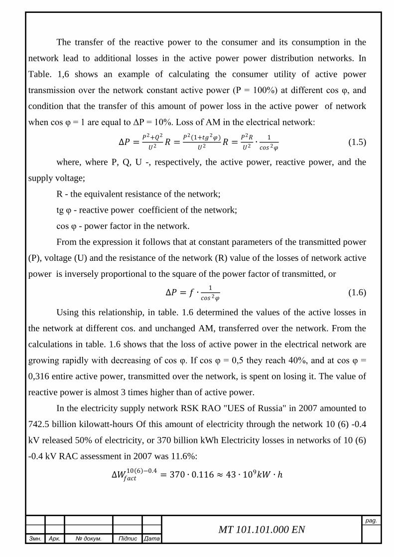
Змн Арк докум Підпис Дата
pag
MT 101101000 EN
The transfer of the reactive power to the consumer and its consumption in the
network lead to additional losses in the active power power distribution networks In
Table 16 shows an example of calculating the consumer utility of active power
transmission over the network constant active power (P = 100) at different cos φ and
condition that the transfer of this amount of power loss in the active power of network
when cos φ = 1 are equal to ΔP = 10 Loss of AM in the electrical network
∆119875119875 = 1198751198752+1198761198762
1198801198802 119877119877 = 1198751198752(1+1199051199051199051199052120593120593)1198801198802 119877119877 = 1198751198752119877119877
1198801198802 ∙1
119888119888119888119888119888119888 2120593120593 (15)
where where P Q U - respectively the active power reactive power and the
supply voltage
R - the equivalent resistance of the network
tg φ - reactive power coefficient of the network
cos φ - power factor in the network
From the expression it follows that at constant parameters of the transmitted power
(P) voltage (U) and the resistance of the network (R) value of the losses of network active
power is inversely proportional to the square of the power factor of transmitted or
∆119875119875 = 119891119891 ∙ 1119888119888119888119888119888119888 2120593120593
(16)
Using this relationship in table 16 determined the values of the active losses in
the network at different cos and unchanged AM transferred over the network From the
calculations in table 16 shows that the loss of active power in the electrical network are
growing rapidly with decreasing of cos φ If cos φ = 05 they reach 40 and at cos φ =
0316 entire active power transmitted over the network is spent on losing it The value of
reactive power is almost 3 times higher than of active power
In the electricity supply network RSK RAO UES of Russia in 2007 amounted to
7425 billion kilowatt-hours Of this amount of electricity through the network 10 (6) -04
kV released 50 of electricity or 370 billion kWh Electricity losses in networks of 10 (6)
-04 kV RAC assessment in 2007 was 116
∆11988211988211989111989111989111989111988811988811990511990510(6)minus04 = 370 ∙ 0116 asymp 43 ∙ 109119896119896119882119882 ∙ ℎ
Змн Арк докум Підпис Дата
pag
MT 101101000 EN
We assume that due to the measures to optimize the balance of the reactive power
of network cos φ is increased by 001 Then the projected loss of power reduced to a value
of
∆11988211988211989111989111988811988811989111989111989111989111988811988811989111989111988811988811990511990510(6)minus04 = 43 ∙ 109 0852
0862 asymp 42 ∙ 109119896119896119882119882 ∙ ℎ
Consequently we can tentatively assume that the increase in the overall power
factor in electric networks 10 (6) -04 kV RAC 001 (12) will save 1 billion kWh of
electricity at an average cost of a kWh at the wholesale electricity market in Russia in
2007 at a rate of 068 rubles will make annual savings of 680 million rubles or more than
28 million US dollars per year This does not exhaust the economic importance of
improving the power factor
Increasing the power factor of 001 in the networks of 10 (6) -04 kV SSC releases
power generators to power about 150 thousand kW If we consider that for the production
of 11 billion kWh of electricity should be about 0370 million tons of standard fuel which
must be obtained from the bowels of the earth to spend a great work on the production
and delivery to the plant providing electricity generation we can provide all the economic
benefits in the economy from reduced consumption of reactive power Increased
consumption of reactive power from the network at low values of cos φ calls for increased
cross-sections of wires and cables in power networks in order to reduce losses If cos φ 07
overruns caused by non-ferrous metals (copper and aluminum) will be more than 50
Low cos φ leads to excessive load of reactive power transmission in step-down
substations so needs of increasing the power of transformers or their number Increased
network load reactive current causes a drop voltage and sharp fluctuations in the value of
the reactive power - fluctuations in voltage and consequently the deterioration of the
quality of electricity allocated by consumers
Змн Арк докум Підпис Дата
pag
MT 101101000 EN
Table 11
Value of reactive power in dependence on cos φ
(in percentage of active power) cosφ 10 099 097 095 094 092 09 087 085 08 07 05 0316
tgφ 0 014 025 033 036 043 0484 055 06 075 102 173 3016
Q 0 14 25 33 36 43 484 55 60 75 102 173 3016
Table 12
Value of active losses with different cos φ and constant active power
transferred in the network
cosφ tgφ Power Active losses
ΔP=10cos2φ
Useful active power of user
(P- ΔP) in of P Reactive Q=P tgφ Total S=Pcosφ
1 0 0 100 10 90 09 0484 484 1111 123 877 08 075 75 125 156 844 07 102 102 1429 204 796 05 173 1732 200 40 60
0316 3016 3016 3165 -100 0
At present the nature of public utilities load has changed dramatically as a result
of the wide spread of new types of power consumers (microwave ovens air conditioners
freezers fluorescent lamps washing machines and dishwashers personal computers etc)
consuming from the feed network along with active power also a significant reactive
power As early as 1987 the Ministry of Energy and Electrification of the USSR [9]
established the extent of compensation of reactive power in the amount of cos φ = 0858
(tg φ = 06) At the same time on different expert estimates the power factor in
distribution networks has a value of about 08-085 (tg φ = 075-062)
In 2007 in Russia requirement for the minimum value of the coefficient of the
reactive power for the consumer connection points to the power supply 10 (6) -04 kV was
considerably stiffened and set cos φ = 0944 (tg φ = 035) for network 04 kV and cos φ =
093 (tg φ = 04) for a network of 6-20 kV
Змн Арк докум Підпис Дата
pag
MT 101101000 EN
As is known the use of compensation can significantly improve the technical and
economic performance of power distribution networks with a voltage of 10 (6) -04 kV
due to
1) reducing the loss of active power
2) increasing the capacity of step-down transformer 10 (6) 04 kV
To estimate the degree of reduction of losses of active power assume that N
transformer substations 10 (6) 04 kV (TS) with the rated capacity of Sn (kW) powered
by a radial scheme from the power supply unit (FS) The transformers are equally loaded
with capacity S with the power factor cos φ Cable (air) line at full compensation on the
side of 04 kV the AM loss of Ts in the distribution network will be equal (neglecting
losses of reactive power in transformers 10 (6) 04 kV)
∆119875119875119897119897prime = 119873119873 ∙ (1198751198752 ∙ 1198771198770119891119891119886119886 ∙ 119871119871119898119898119898119898119898119898 ∙ 10minus3)1198801198801198991198992 kW (17)
Losses of active power during the actual loading S (in the absence of
compensation)
∆119875119875119897119897 = 119873119873 ∙ (1198781198782 ∙ 1198771198770119891119891119886119886 ∙ 119871119871119898119898119898119898119898119898 ∙ 10minus3)1198801198801198991198992 kW (18)
where Roav - the average value of specific resistance of supply lines from the FS
to the TS Ohm km Lav - the average length of supply lines from the FS to the TS km
Un-rated voltage of the electrical network kV
The ratio values of these losses can be characterized by the appropriate factor
119870119870119888119888 = ∆119875119875119897119897∆119875119875119897119897
prime = 1198781198782
1198751198752 = 1119888119888119888119888119888119888 2120593120593
(19)
The lower the value of the previous power factor the higher the efficiency of
compensation
Considering that the actual power factor in power distribution networks 10(6) -
04 kV is about 08-085 it is easy to see that the loss of active power in the distribution
network after installing condenser units can be reduced to 138-156 times or 27-36
Змн Арк докум Підпис Дата
pag
MT 101101000 EN
Table 13
Dependence of compensation on power factor in cable and overhead lines
cos φ 08 085 09 095 10
Kc 1563 1384 1235 1108 10
Losses in transformers AM are characterized by a complex dependence compared
to the power lines
∆119875119875119905119905119891119891 = 119873119873 ∙ (∆119875119875119899119899119897119897 + 1205731205732 ∙ ∆119875119875119888119888119888119888) (110)
where 119875119875119899119899119897119897 is no-load losses kW ∆119875119875119888119888119888119888 is short circuit losses kW 120573120573 = 119878119878119878119878119899119899 is ratio
of loading of transformer by total power
With full compensation on 04 kV losses of active power will reduce and would be
equal
∆119875119875prime119905119905119891119891 = 119873119873 ∙ (∆119875119875119899119899119897119897 + 1205721205722 ∙ ∆119875119875119888119888119888119888) (111)
where α= 119875119875119878119878119899119899 is ratio of loading of transformer by active power
The ratio values of these losses can be calculated from following formula
119870119870119888119888 = 119873119873∙(∆119875119875119899119899119897119897 +1205731205732∙∆119875119875119888119888119888119888)119873119873∙(∆119875119875119899119899119897119897 +1205721205722∙∆119875119875119888119888119888119888)
= (1+1205731205732∙∆119875119875119888119888119888119888∆119875119875119899119899119897119897 )1+1205721205722∙∆119875119875119888119888119888119888∆119875119875119899119899119897119897
(112)
In the particular case with load of transformer on nominal capacity will have β=1
α=PSn= cos φ Then the last expression can be put in the form
119870119870119888119888 = (1+119870119870119891119891)(1+119870119870119891119891∙119888119888119888119888119888119888 2120593120593)
(113)
where Kr =∆119875119875119888119888119888119888∆119875119875119899119899119897119897
= 60 is the coefficient characterizing the ratio of losses of short
circuit to the losses of no-load in transformers with capacity of 400-1000 kVA
Analysis of the data presented in Table 4 shows that due to no-load losses which
do not depend on the load the degree of reduction of losses in transformers AM when
installing BC will be somewhat less than in the cable or overhead lines Thus the loss of
AM in the step-down transformer 10 (6) 04 kV after installing BC can be reduced to
131-144 times or 24-31
Змн Арк докум Підпис Дата
pag
MT 101101000 EN
Table 14
Dependence of compensation on power factor in step-down transformers
cos φ 08 085 09 095 10
Kc 1446 1312 1195 1091 10
The calculations show that the main effect in reducing the technical losses of
electricity can be produced by modernization renovation improving throughput and
reliability of electrical networks a balance of modes ie through the introduction of
capital-intensive activities
The priority actions to reduce technical losses in electricity distribution networks
04-35 kV are
- the use of 10 kV as the primary voltage distribution network
- increase in the proportion of networks with a voltage of 35 kV
- reduction in range and construction of overhead lines (04 kV) in the three-
phase over the entire length
- the use of self-supporting insulated and protected wires for voltage 04-10 kV
overhead line
- using the maximum allowable cross section wires in the electrical voltage of
04-10 kV networks in order to adapt their carrying capacity to increase load
during the entire period of service
- development and introduction of new more cost-effective electrical
equipment such as distribution transformers with reduced active and reactive
losses idling and embedded in the CTS and ITS capacitor banks
- the use of low power transformers pillar (6-100 4 kV) to reduce the length of
the network voltage of 04 kV and the energy losses in them
- greater use of the automatic voltage regulation under load booster transformers
voltage regulation of the local to improve power quality and reduce its losses
Змн Арк докум Підпис Дата
pag
MT 101101000 EN
- complex automation and telemechanization electrical networks the use of
switching devices of new generation of remote fault location in networks to
reduce the duration of nonoptimal repair and post-emergency modes search
and emergency response
- improving the reliability of measurements in networks using new information
technologies automation processing telemetry data
14 Task of the research
- Calculation and selection of main power supply elements of industry
- Analysis of implementation of methods of power loss reduction
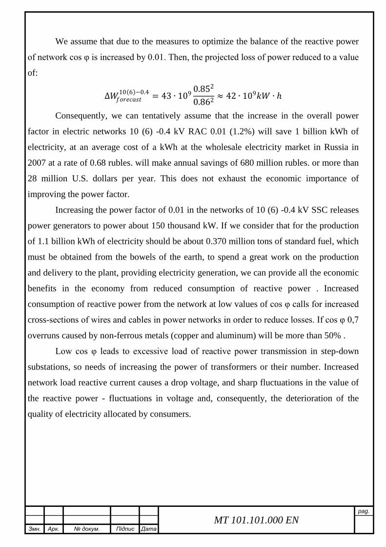
Змн Арк докум Підпис Дата
pag
MT 101101000 EN
Table 11
Value of reactive power in dependence on cos φ
(in percentage of active power) cosφ 10 099 097 095 094 092 09 087 085 08 07 05 0316
tgφ 0 014 025 033 036 043 0484 055 06 075 102 173 3016
Q 0 14 25 33 36 43 484 55 60 75 102 173 3016
Table 12
Value of active losses with different cos φ and constant active power
transferred in the network
cosφ tgφ Power Active losses
ΔP=10cos2φ
Useful active power of user
(P- ΔP) in of P Reactive Q=P tgφ Total S=Pcosφ
1 0 0 100 10 90 09 0484 484 1111 123 877 08 075 75 125 156 844 07 102 102 1429 204 796 05 173 1732 200 40 60
0316 3016 3016 3165 -100 0
At present the nature of public utilities load has changed dramatically as a result
of the wide spread of new types of power consumers (microwave ovens air conditioners
freezers fluorescent lamps washing machines and dishwashers personal computers etc)
consuming from the feed network along with active power also a significant reactive
power As early as 1987 the Ministry of Energy and Electrification of the USSR [9]
established the extent of compensation of reactive power in the amount of cos φ = 0858
(tg φ = 06) At the same time on different expert estimates the power factor in
distribution networks has a value of about 08-085 (tg φ = 075-062)
In 2007 in Russia requirement for the minimum value of the coefficient of the
reactive power for the consumer connection points to the power supply 10 (6) -04 kV was
considerably stiffened and set cos φ = 0944 (tg φ = 035) for network 04 kV and cos φ =
093 (tg φ = 04) for a network of 6-20 kV
Змн Арк докум Підпис Дата
pag
MT 101101000 EN
As is known the use of compensation can significantly improve the technical and
economic performance of power distribution networks with a voltage of 10 (6) -04 kV
due to
1) reducing the loss of active power
2) increasing the capacity of step-down transformer 10 (6) 04 kV
To estimate the degree of reduction of losses of active power assume that N
transformer substations 10 (6) 04 kV (TS) with the rated capacity of Sn (kW) powered
by a radial scheme from the power supply unit (FS) The transformers are equally loaded
with capacity S with the power factor cos φ Cable (air) line at full compensation on the
side of 04 kV the AM loss of Ts in the distribution network will be equal (neglecting
losses of reactive power in transformers 10 (6) 04 kV)
∆119875119875119897119897prime = 119873119873 ∙ (1198751198752 ∙ 1198771198770119891119891119886119886 ∙ 119871119871119898119898119898119898119898119898 ∙ 10minus3)1198801198801198991198992 kW (17)
Losses of active power during the actual loading S (in the absence of
compensation)
∆119875119875119897119897 = 119873119873 ∙ (1198781198782 ∙ 1198771198770119891119891119886119886 ∙ 119871119871119898119898119898119898119898119898 ∙ 10minus3)1198801198801198991198992 kW (18)
where Roav - the average value of specific resistance of supply lines from the FS
to the TS Ohm km Lav - the average length of supply lines from the FS to the TS km
Un-rated voltage of the electrical network kV
The ratio values of these losses can be characterized by the appropriate factor
119870119870119888119888 = ∆119875119875119897119897∆119875119875119897119897
prime = 1198781198782
1198751198752 = 1119888119888119888119888119888119888 2120593120593
(19)
The lower the value of the previous power factor the higher the efficiency of
compensation
Considering that the actual power factor in power distribution networks 10(6) -
04 kV is about 08-085 it is easy to see that the loss of active power in the distribution
network after installing condenser units can be reduced to 138-156 times or 27-36
Змн Арк докум Підпис Дата
pag
MT 101101000 EN
Table 13
Dependence of compensation on power factor in cable and overhead lines
cos φ 08 085 09 095 10
Kc 1563 1384 1235 1108 10
Losses in transformers AM are characterized by a complex dependence compared
to the power lines
∆119875119875119905119905119891119891 = 119873119873 ∙ (∆119875119875119899119899119897119897 + 1205731205732 ∙ ∆119875119875119888119888119888119888) (110)
where 119875119875119899119899119897119897 is no-load losses kW ∆119875119875119888119888119888119888 is short circuit losses kW 120573120573 = 119878119878119878119878119899119899 is ratio
of loading of transformer by total power
With full compensation on 04 kV losses of active power will reduce and would be
equal
∆119875119875prime119905119905119891119891 = 119873119873 ∙ (∆119875119875119899119899119897119897 + 1205721205722 ∙ ∆119875119875119888119888119888119888) (111)
where α= 119875119875119878119878119899119899 is ratio of loading of transformer by active power
The ratio values of these losses can be calculated from following formula
119870119870119888119888 = 119873119873∙(∆119875119875119899119899119897119897 +1205731205732∙∆119875119875119888119888119888119888)119873119873∙(∆119875119875119899119899119897119897 +1205721205722∙∆119875119875119888119888119888119888)
= (1+1205731205732∙∆119875119875119888119888119888119888∆119875119875119899119899119897119897 )1+1205721205722∙∆119875119875119888119888119888119888∆119875119875119899119899119897119897
(112)
In the particular case with load of transformer on nominal capacity will have β=1
α=PSn= cos φ Then the last expression can be put in the form
119870119870119888119888 = (1+119870119870119891119891)(1+119870119870119891119891∙119888119888119888119888119888119888 2120593120593)
(113)
where Kr =∆119875119875119888119888119888119888∆119875119875119899119899119897119897
= 60 is the coefficient characterizing the ratio of losses of short
circuit to the losses of no-load in transformers with capacity of 400-1000 kVA
Analysis of the data presented in Table 4 shows that due to no-load losses which
do not depend on the load the degree of reduction of losses in transformers AM when
installing BC will be somewhat less than in the cable or overhead lines Thus the loss of
AM in the step-down transformer 10 (6) 04 kV after installing BC can be reduced to
131-144 times or 24-31
Змн Арк докум Підпис Дата
pag
MT 101101000 EN
Table 14
Dependence of compensation on power factor in step-down transformers
cos φ 08 085 09 095 10
Kc 1446 1312 1195 1091 10
The calculations show that the main effect in reducing the technical losses of
electricity can be produced by modernization renovation improving throughput and
reliability of electrical networks a balance of modes ie through the introduction of
capital-intensive activities
The priority actions to reduce technical losses in electricity distribution networks
04-35 kV are
- the use of 10 kV as the primary voltage distribution network
- increase in the proportion of networks with a voltage of 35 kV
- reduction in range and construction of overhead lines (04 kV) in the three-
phase over the entire length
- the use of self-supporting insulated and protected wires for voltage 04-10 kV
overhead line
- using the maximum allowable cross section wires in the electrical voltage of
04-10 kV networks in order to adapt their carrying capacity to increase load
during the entire period of service
- development and introduction of new more cost-effective electrical
equipment such as distribution transformers with reduced active and reactive
losses idling and embedded in the CTS and ITS capacitor banks
- the use of low power transformers pillar (6-100 4 kV) to reduce the length of
the network voltage of 04 kV and the energy losses in them
- greater use of the automatic voltage regulation under load booster transformers
voltage regulation of the local to improve power quality and reduce its losses
Змн Арк докум Підпис Дата
pag
MT 101101000 EN
- complex automation and telemechanization electrical networks the use of
switching devices of new generation of remote fault location in networks to
reduce the duration of nonoptimal repair and post-emergency modes search
and emergency response
- improving the reliability of measurements in networks using new information
technologies automation processing telemetry data
14 Task of the research
- Calculation and selection of main power supply elements of industry
- Analysis of implementation of methods of power loss reduction
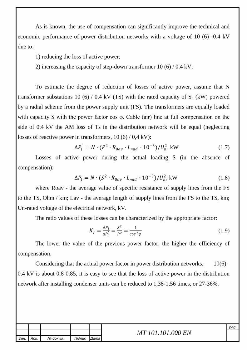
Змн Арк докум Підпис Дата
pag
MT 101101000 EN
As is known the use of compensation can significantly improve the technical and
economic performance of power distribution networks with a voltage of 10 (6) -04 kV
due to
1) reducing the loss of active power
2) increasing the capacity of step-down transformer 10 (6) 04 kV
To estimate the degree of reduction of losses of active power assume that N
transformer substations 10 (6) 04 kV (TS) with the rated capacity of Sn (kW) powered
by a radial scheme from the power supply unit (FS) The transformers are equally loaded
with capacity S with the power factor cos φ Cable (air) line at full compensation on the
side of 04 kV the AM loss of Ts in the distribution network will be equal (neglecting
losses of reactive power in transformers 10 (6) 04 kV)
∆119875119875119897119897prime = 119873119873 ∙ (1198751198752 ∙ 1198771198770119891119891119886119886 ∙ 119871119871119898119898119898119898119898119898 ∙ 10minus3)1198801198801198991198992 kW (17)
Losses of active power during the actual loading S (in the absence of
compensation)
∆119875119875119897119897 = 119873119873 ∙ (1198781198782 ∙ 1198771198770119891119891119886119886 ∙ 119871119871119898119898119898119898119898119898 ∙ 10minus3)1198801198801198991198992 kW (18)
where Roav - the average value of specific resistance of supply lines from the FS
to the TS Ohm km Lav - the average length of supply lines from the FS to the TS km
Un-rated voltage of the electrical network kV
The ratio values of these losses can be characterized by the appropriate factor
119870119870119888119888 = ∆119875119875119897119897∆119875119875119897119897
prime = 1198781198782
1198751198752 = 1119888119888119888119888119888119888 2120593120593
(19)
The lower the value of the previous power factor the higher the efficiency of
compensation
Considering that the actual power factor in power distribution networks 10(6) -
04 kV is about 08-085 it is easy to see that the loss of active power in the distribution
network after installing condenser units can be reduced to 138-156 times or 27-36
Змн Арк докум Підпис Дата
pag
MT 101101000 EN
Table 13
Dependence of compensation on power factor in cable and overhead lines
cos φ 08 085 09 095 10
Kc 1563 1384 1235 1108 10
Losses in transformers AM are characterized by a complex dependence compared
to the power lines
∆119875119875119905119905119891119891 = 119873119873 ∙ (∆119875119875119899119899119897119897 + 1205731205732 ∙ ∆119875119875119888119888119888119888) (110)
where 119875119875119899119899119897119897 is no-load losses kW ∆119875119875119888119888119888119888 is short circuit losses kW 120573120573 = 119878119878119878119878119899119899 is ratio
of loading of transformer by total power
With full compensation on 04 kV losses of active power will reduce and would be
equal
∆119875119875prime119905119905119891119891 = 119873119873 ∙ (∆119875119875119899119899119897119897 + 1205721205722 ∙ ∆119875119875119888119888119888119888) (111)
where α= 119875119875119878119878119899119899 is ratio of loading of transformer by active power
The ratio values of these losses can be calculated from following formula
119870119870119888119888 = 119873119873∙(∆119875119875119899119899119897119897 +1205731205732∙∆119875119875119888119888119888119888)119873119873∙(∆119875119875119899119899119897119897 +1205721205722∙∆119875119875119888119888119888119888)
= (1+1205731205732∙∆119875119875119888119888119888119888∆119875119875119899119899119897119897 )1+1205721205722∙∆119875119875119888119888119888119888∆119875119875119899119899119897119897
(112)
In the particular case with load of transformer on nominal capacity will have β=1
α=PSn= cos φ Then the last expression can be put in the form
119870119870119888119888 = (1+119870119870119891119891)(1+119870119870119891119891∙119888119888119888119888119888119888 2120593120593)
(113)
where Kr =∆119875119875119888119888119888119888∆119875119875119899119899119897119897
= 60 is the coefficient characterizing the ratio of losses of short
circuit to the losses of no-load in transformers with capacity of 400-1000 kVA
Analysis of the data presented in Table 4 shows that due to no-load losses which
do not depend on the load the degree of reduction of losses in transformers AM when
installing BC will be somewhat less than in the cable or overhead lines Thus the loss of
AM in the step-down transformer 10 (6) 04 kV after installing BC can be reduced to
131-144 times or 24-31
Змн Арк докум Підпис Дата
pag
MT 101101000 EN
Table 14
Dependence of compensation on power factor in step-down transformers
cos φ 08 085 09 095 10
Kc 1446 1312 1195 1091 10
The calculations show that the main effect in reducing the technical losses of
electricity can be produced by modernization renovation improving throughput and
reliability of electrical networks a balance of modes ie through the introduction of
capital-intensive activities
The priority actions to reduce technical losses in electricity distribution networks
04-35 kV are
- the use of 10 kV as the primary voltage distribution network
- increase in the proportion of networks with a voltage of 35 kV
- reduction in range and construction of overhead lines (04 kV) in the three-
phase over the entire length
- the use of self-supporting insulated and protected wires for voltage 04-10 kV
overhead line
- using the maximum allowable cross section wires in the electrical voltage of
04-10 kV networks in order to adapt their carrying capacity to increase load
during the entire period of service
- development and introduction of new more cost-effective electrical
equipment such as distribution transformers with reduced active and reactive
losses idling and embedded in the CTS and ITS capacitor banks
- the use of low power transformers pillar (6-100 4 kV) to reduce the length of
the network voltage of 04 kV and the energy losses in them
- greater use of the automatic voltage regulation under load booster transformers
voltage regulation of the local to improve power quality and reduce its losses
Змн Арк докум Підпис Дата
pag
MT 101101000 EN
- complex automation and telemechanization electrical networks the use of
switching devices of new generation of remote fault location in networks to
reduce the duration of nonoptimal repair and post-emergency modes search
and emergency response
- improving the reliability of measurements in networks using new information
technologies automation processing telemetry data
14 Task of the research
- Calculation and selection of main power supply elements of industry
- Analysis of implementation of methods of power loss reduction
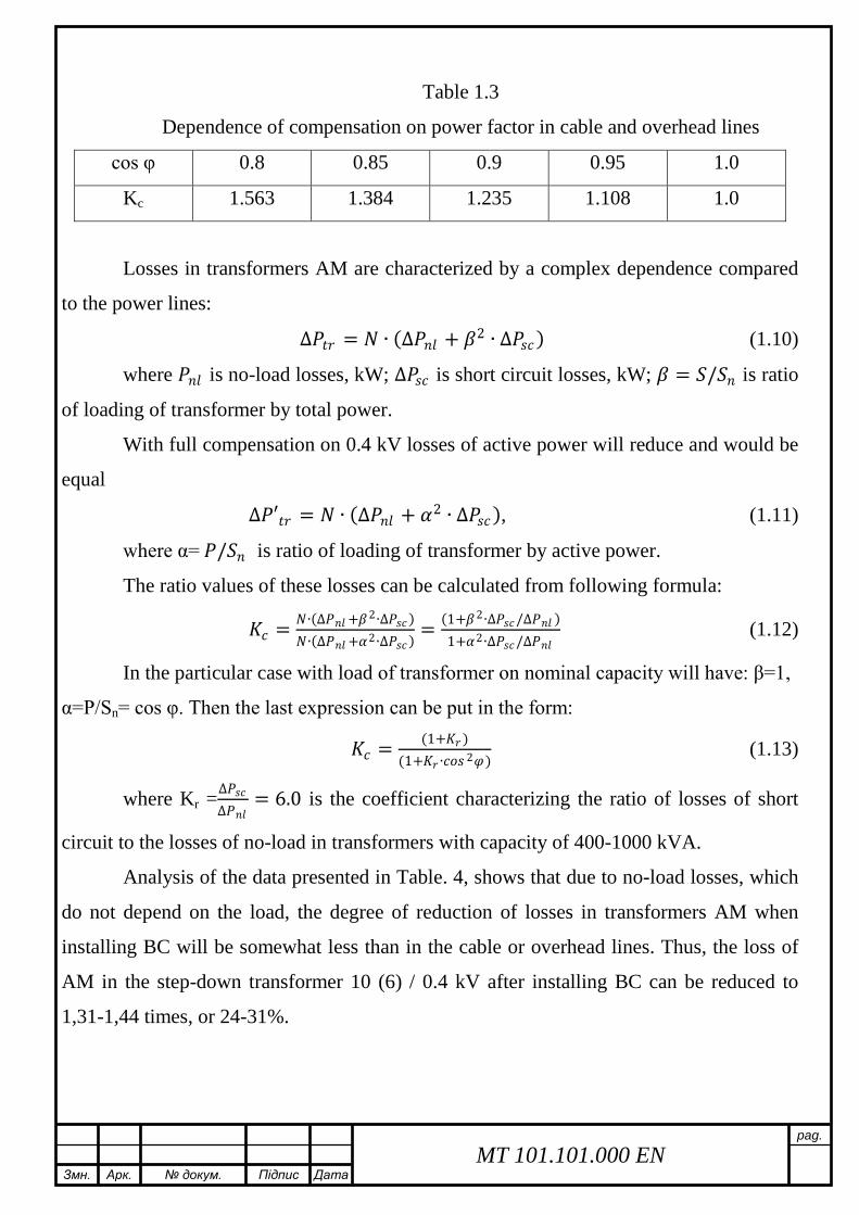
Змн Арк докум Підпис Дата
pag
MT 101101000 EN
Table 13
Dependence of compensation on power factor in cable and overhead lines
cos φ 08 085 09 095 10
Kc 1563 1384 1235 1108 10
Losses in transformers AM are characterized by a complex dependence compared
to the power lines
∆119875119875119905119905119891119891 = 119873119873 ∙ (∆119875119875119899119899119897119897 + 1205731205732 ∙ ∆119875119875119888119888119888119888) (110)
where 119875119875119899119899119897119897 is no-load losses kW ∆119875119875119888119888119888119888 is short circuit losses kW 120573120573 = 119878119878119878119878119899119899 is ratio
of loading of transformer by total power
With full compensation on 04 kV losses of active power will reduce and would be
equal
∆119875119875prime119905119905119891119891 = 119873119873 ∙ (∆119875119875119899119899119897119897 + 1205721205722 ∙ ∆119875119875119888119888119888119888) (111)
where α= 119875119875119878119878119899119899 is ratio of loading of transformer by active power
The ratio values of these losses can be calculated from following formula
119870119870119888119888 = 119873119873∙(∆119875119875119899119899119897119897 +1205731205732∙∆119875119875119888119888119888119888)119873119873∙(∆119875119875119899119899119897119897 +1205721205722∙∆119875119875119888119888119888119888)
= (1+1205731205732∙∆119875119875119888119888119888119888∆119875119875119899119899119897119897 )1+1205721205722∙∆119875119875119888119888119888119888∆119875119875119899119899119897119897
(112)
In the particular case with load of transformer on nominal capacity will have β=1
α=PSn= cos φ Then the last expression can be put in the form
119870119870119888119888 = (1+119870119870119891119891)(1+119870119870119891119891∙119888119888119888119888119888119888 2120593120593)
(113)
where Kr =∆119875119875119888119888119888119888∆119875119875119899119899119897119897
= 60 is the coefficient characterizing the ratio of losses of short
circuit to the losses of no-load in transformers with capacity of 400-1000 kVA
Analysis of the data presented in Table 4 shows that due to no-load losses which
do not depend on the load the degree of reduction of losses in transformers AM when
installing BC will be somewhat less than in the cable or overhead lines Thus the loss of
AM in the step-down transformer 10 (6) 04 kV after installing BC can be reduced to
131-144 times or 24-31
Змн Арк докум Підпис Дата
pag
MT 101101000 EN
Table 14
Dependence of compensation on power factor in step-down transformers
cos φ 08 085 09 095 10
Kc 1446 1312 1195 1091 10
The calculations show that the main effect in reducing the technical losses of
electricity can be produced by modernization renovation improving throughput and
reliability of electrical networks a balance of modes ie through the introduction of
capital-intensive activities
The priority actions to reduce technical losses in electricity distribution networks
04-35 kV are
- the use of 10 kV as the primary voltage distribution network
- increase in the proportion of networks with a voltage of 35 kV
- reduction in range and construction of overhead lines (04 kV) in the three-
phase over the entire length
- the use of self-supporting insulated and protected wires for voltage 04-10 kV
overhead line
- using the maximum allowable cross section wires in the electrical voltage of
04-10 kV networks in order to adapt their carrying capacity to increase load
during the entire period of service
- development and introduction of new more cost-effective electrical
equipment such as distribution transformers with reduced active and reactive
losses idling and embedded in the CTS and ITS capacitor banks
- the use of low power transformers pillar (6-100 4 kV) to reduce the length of
the network voltage of 04 kV and the energy losses in them
- greater use of the automatic voltage regulation under load booster transformers
voltage regulation of the local to improve power quality and reduce its losses
Змн Арк докум Підпис Дата
pag
MT 101101000 EN
- complex automation and telemechanization electrical networks the use of
switching devices of new generation of remote fault location in networks to
reduce the duration of nonoptimal repair and post-emergency modes search
and emergency response
- improving the reliability of measurements in networks using new information
technologies automation processing telemetry data
14 Task of the research
- Calculation and selection of main power supply elements of industry
- Analysis of implementation of methods of power loss reduction
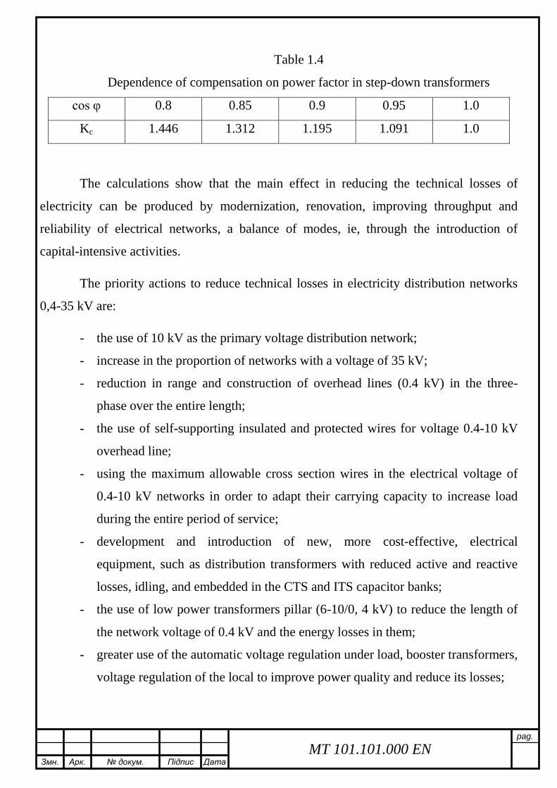
Змн Арк докум Підпис Дата
pag
MT 101101000 EN
Table 14
Dependence of compensation on power factor in step-down transformers
cos φ 08 085 09 095 10
Kc 1446 1312 1195 1091 10
The calculations show that the main effect in reducing the technical losses of
electricity can be produced by modernization renovation improving throughput and
reliability of electrical networks a balance of modes ie through the introduction of
capital-intensive activities
The priority actions to reduce technical losses in electricity distribution networks
04-35 kV are
- the use of 10 kV as the primary voltage distribution network
- increase in the proportion of networks with a voltage of 35 kV
- reduction in range and construction of overhead lines (04 kV) in the three-
phase over the entire length
- the use of self-supporting insulated and protected wires for voltage 04-10 kV
overhead line
- using the maximum allowable cross section wires in the electrical voltage of
04-10 kV networks in order to adapt their carrying capacity to increase load
during the entire period of service
- development and introduction of new more cost-effective electrical
equipment such as distribution transformers with reduced active and reactive
losses idling and embedded in the CTS and ITS capacitor banks
- the use of low power transformers pillar (6-100 4 kV) to reduce the length of
the network voltage of 04 kV and the energy losses in them
- greater use of the automatic voltage regulation under load booster transformers
voltage regulation of the local to improve power quality and reduce its losses
Змн Арк докум Підпис Дата
pag
MT 101101000 EN
- complex automation and telemechanization electrical networks the use of
switching devices of new generation of remote fault location in networks to
reduce the duration of nonoptimal repair and post-emergency modes search
and emergency response
- improving the reliability of measurements in networks using new information
technologies automation processing telemetry data
14 Task of the research
- Calculation and selection of main power supply elements of industry
- Analysis of implementation of methods of power loss reduction