Embed Size (px)
Citation preview

ML442 | v5k 14-July-17
MiniPurge Type X Size 1 Manual
ML 442
Contents 1. Specification Sheet – MiniPurge Type X Systems 2. Application Suitability 3. Description and Principle of Operation 4. Installation of the System 5. Commissioning 6. Maintenance of the System 7. Fault Finding 8. Approval Documents 9. Glossary


ML442 | v5k Page
1 Expo Technologies UK T: +44 (0) 20 8398 8011 E: [email protected]
Expo Technologies US T: +1 (440) 247 5314 E:[email protected]
Expo Technologies China T: +86 532 8906 9858 E: [email protected]
Approval / Certification
X = Europe EN60079-0, EN60079-2 Sira 01ATEX1295X
0518 II 2 (2) G D Ex [pxb] IIC T6 Gb Ex [pxb] IIIC T85ºC Db Tamb -20ºC +55ºC
IEC IEC60079-0, IEC60079-2 IECEx SIR 07.0027X Ex [pxb] IIC T6 Gb Ex [pxb] IIIC T85ºC Db Tamb -20ºC +55ºC
BRAZIL INMETRO- TÜV 12.1462X Ex [pxb] IIC T6 Gb Ex [pxb] IIIC T85ºC Db Tamb -20ºC +55ºC
USA / Canada NFPA 496 FM 1X8A4AE Class I Div 1 Groups A, B, C & D UL E190061 Class I Div 1 Groups A, B, C & D For limitations and conditions of use refer to the applicable certificate at the back of this manual.
MiniPurge Housing
ss = 316L Stainless Steel Neoprene “Top” Mount Gasket pm = Panel Mount (Side/Front Mount) 316L
Stainless Steel
Presurization Method
CF = Continuous Flow LC = Leakage Compensation
1. Specification Sheet – MiniPurge Type X Systems Supply Pressure: Must be regulated at inlet Minimum 60 psi / 0.4 MPa / 4 bar Maximum 115 psi / 0.8 MPa / 8 bar Air Quality: Compressed air / Nitrogen to instrument quality Ambient Temperature: -20ºC to + 55ºC Leakage Compensation: Variable up to 2 scfm / 60 Nl/min to compensate for leakage of enclosure Purge Timer: Stepped adjustable between 1 minute and 30 minutes Flow & Pressure Sensors: CF: One sensor for both “Low Pressure and Flow”: 1” WC / 250 Pa (2.5 mbar) LC: “Low Pressure Sensor” 0.2” WC / 50 Pa (0.5 mbar) “Flow Sensor” 1.13” WC/ 280 Pa / (2.8 mbar) Relief Valve: System: CF LC Model No: RLV25/ss RLV25/FS/ss Opening Pressure: 4” WC / 1 kPa (10 mbar) 4” WC / 1 kPa (10 mbar) Purge Flow Rate: N/A (see Spark Arrestor) 8 scfm / 225 Nl/min Material: 316L Stainless Steel, Spark Arrestor: Stainless Steel mesh, Gasket: Neoprene Spark Arrestor Unit Model No: SAU25 (CF systems only) Purge / Dilution Flow Rate: Between 0.4 & 8 scfm / 10 & 225 Nl/min (Default: 8 scfm) 7 user selectable orifice plates Material: Stainless Steel Bulkhead Pipe Fittings: Air Supply: 1/2” NPT Output: 1/2” NPT Signal: 1/8” NPT
Size 1 = Sub MiniPurge Purge flow rate 225 Nl /min, 8 scfm
Purge System Type
07 = MiniPurge
Power & Alarm (Signals)
PO = Pneumatic Output “Power” : On Purge Complete = 30 psi / 0.2 MPa / 2 bar Signal “Alarm” : Loss of Pressure = No signal ”Pressurized” = 30 psi / 0.2 MPa / 2 bar Signal
PA = Power and Alarm Terminal Box Ex e IIC T5 Power and Alarm Terminal Box Ex e IIC T4 “Power” ; 250 Vac 4 Amp AC15 2PNO – Ex d IIC T6 “Alarm” : 250 Vac 4 Amp AC15 SPCO – Ex d IIC T6 (European and IEC Systems Only)
IS = Intrinsically Safe, Ex i & Ex i circuit “Power” : used with others’ Ex i equipment “Alarm” : Relay / Barrier
Model No. (Example): 07 1 XLC / ss / PO / WM (Note: Not all codes are applicable)
Options as Required
AO = Alarm Only MO = Manual Override MK = MIU Mounting Kit (PO systems only) WM = Wall Mounting Bars

Page 2
ML442 | v5kExpo Technologies UK T: +44 (0) 20 8398 8011
Expo Technologies UST: +1 (440) 247 5314
Expo Technologies ChinaT: +86 532 8906 9858
Visual Indicators: CF: Alarm / Pressurized (Red / Green) Purge Complete (Red / Green) LC: Alarm / Pressurized (Red / Green) Purge Complete (Black / Amber) Action on “Loss of Pressure”: CF: Action on “Loss of Pressure” = “Alarm & Trip”. Option /AO specifies an “Alarm Only” kit. LC: Action on “Loss of Pressure” = “Alarm & Trip” or “Alarm Only”. LC Model is user selectable.
ML442 | v5k Page
3 Expo Technologies UK T: +44 (0) 20 8398 8011 E: [email protected]
Expo Technologies US T: +1 (440) 247 5314 E:[email protected]
Expo Technologies China T: +86 532 8906 9858 E: [email protected]
2. Application Suitability MiniPurge Systems are certified for use in Hazardous Areas, where the Hazardous Area is non-mining (i.e. above ground) and the hazard is caused by flammable gasses, vapours or dust. Depending on the model, the systems may be used in IECEx, ATEX Zone 1(21) - Category 2 and NEC 500 Class I, Div 1. MiniPurge systems may be used for hazards of any gas group. However, apparatus associated with the MiniPurge system, such as Intrinsically Safe signalling circuits and flameproof enclosures containing switching devices may be limited in their gas group. The certification documentation supplied with any such devices must be checked to ensure their suitability. This system is designed for use primarily with compressed air. Where other inert compressed gasses are used (Nitrogen, for example) the user must take suitable precautions so that the build-up of the inert gas does not present a hazard to health. Consult the Control of Substances Hazardous to Health (COSHH) data sheet for the gas used. Where a risk of asphyxiation exists, a warning label must be fitted to the Pressurized Enclosure. The following materials are used in the construction of MiniPurge systems. If substances that will adversely affect any of these materials are present in the surrounding environment, please consult Expo for further guidance. Materials of construction:
Stainless Steel Aluminium Acrylic Mild (carbon) Steel Nylon Silicone Rubber Brass Polyurethane Neoprene

Page 4
ML442 | v5kExpo Technologies UK T: +44 (0) 20 8398 8011
Expo Technologies UST: +1 (440) 247 5314
Expo Technologies ChinaT: +86 532 8906 9858
3. Description and Principle of Operation All Expo Technologies MiniPurge pressurization systems provide: a) a method of pressurizing a Pressurized Enclosure (PE) while at the same time compensating for any leakage, together with b) a method of purging the enclosure, before power is applied, to remove any flammable gas that may have entered the enclosure while it was not pressurized, c) visual indication of the MiniPurge system status, and d) an output to provide remote indication or control. The MiniPurge system comprises a number of component units. The units required depend on the type of system selected. These are summarised in Table 1. The general description and function of each is as follows: 3.1 Control Unit (CU) The Control Unit (CU) is the heart of the system. It contains a pneumatic logic circuit specially designed and built to control the functions required for purge and pressurization. For all systems this includes air filtration, pressure and purge flow measurement, purge timing, and local visual indication of Pressurized/Alarm and flow sensed. It also provides the outputs for power and remote alarm control corresponding to the output type selected. 3.2 Relief Valve (RLV)
The Relief Valve unit is fitted to the PE to provide a means of limiting the maximum pressure experienced by the PE during operation. The RLV model number has a suffix giving the diameter of the valve aperture in millimetres e.g. RLV25 (= 25mm bore). The RLV also incorporates a Spark Arrestor to prevent sparks being ejected from the PE into the classified area. In Leakage Compensation systems, the RLV is combined with the flow measurement mechanism.
Figure 1. LC Relief Valve 3.3 Calibrated Outlet Orifice/Spark Arrestor (SAU) Continuous Flow systems incorporate the SAU25. This unit has a range of interchangeable calibrated orifice plates, which are used to measure the flow through the PE.
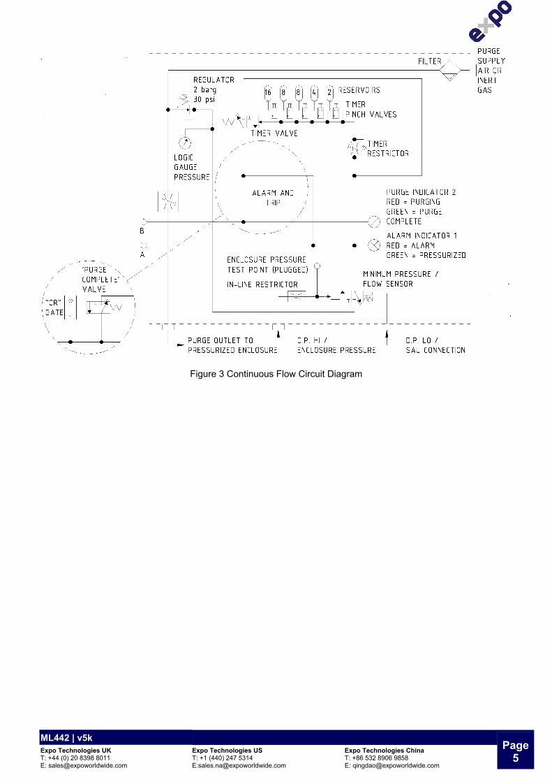
Figure 2 Spark Arrestor Type SAU25 3.4 The Methods of Pressurizing a) CF - Continuous Flow A Continuous Flow (CF) of protective gas is passed through the PE. Initially this flow is verified and performs the purging phase of the operation. When the purging phase is completed – i.e. the purge time has elapsed- the same flow of protective gas maintains the pressurization of the enclosure. This flow may be required to dilute an internal source of hazardous gas release.
ML442 | v5k Page
5 Expo Technologies UK T: +44 (0) 20 8398 8011 E: [email protected]
Expo Technologies US T: +1 (440) 247 5314 E:[email protected]
Expo Technologies China T: +86 532 8906 9858 E: [email protected]
Figure 3 Continuous Flow Circuit Diagram

Page 6
ML442 | v5kExpo Technologies UK T: +44 (0) 20 8398 8011
Expo Technologies UST: +1 (440) 247 5314
Expo Technologies ChinaT: +86 532 8906 9858
b) LC - Leakage Compensation Initially a high flow of protective gas is passed through the enclosure. This flow is verified and performs the purging phase of the operation. When the purging phase is completed – i.e. the purge time has elapsed - the flow of protective gas is provided via an adjustable valve so that it just compensates for any leakage from the PE in addition to maintaining its pressurization. If leakage is less than 5 l/min then the LCV will be awkward to set. You will find that the RLV spring will cycle open and closed. If this happens contact our service department for advice.
Figure 4 Leakage Compensation Circuit Diagram 3.5 Type of Output The functions of the outputs are power control and alarm/pressurized indication. Power control provides a signal to switch the power to the PE. Alarm output provides a passive signal to indicate remotely when the enclosure is not pressurized and an active signal when pressurized. a) PO- Pneumatic Output The power control and pressurized outputs are pneumatic signals, which may be used to operate other devices to provide power switching or alarm indication. The lack of any output signal indicates incomplete purge and alarm. In many instances these outputs may be connected to the Expo range of MiniPurge Interface Unit s (MIU).
Figure 5 Typical MiniPurge Interface Unit type (MIU/dA)
Figure 6 Pneumatic Output Option
ML442 | v5k Page
7 Expo Technologies UK T: +44 (0) 20 8398 8011 E: [email protected]
Expo Technologies US T: +1 (440) 247 5314 E:[email protected]
Expo Technologies China T: +86 532 8906 9858 E: [email protected]
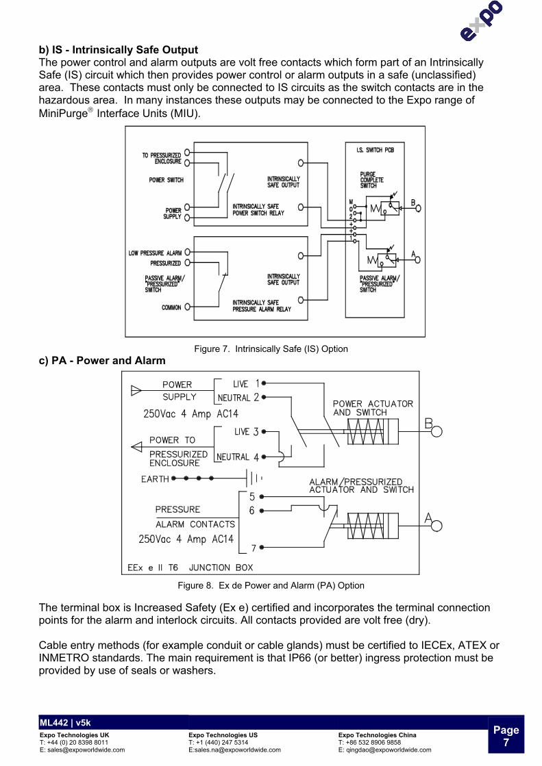
b) IS - Intrinsically Safe Output The power control and alarm outputs are volt free contacts which form part of an Intrinsically Safe (IS) circuit which then provides power control or alarm outputs in a safe (unclassified) area. These contacts must only be connected to IS circuits as the switch contacts are in the hazardous area. In many instances these outputs may be connected to the Expo range of MiniPurge Interface Units (MIU).
Figure 7. Intrinsically Safe (IS) Option c) PA - Power and Alarm
Figure 8. Ex de Power and Alarm (PA) Option
The terminal box is Increased Safety (Ex e) certified and incorporates the terminal connection points for the alarm and interlock circuits. All contacts provided are volt free (dry). Cable entry methods (for example conduit or cable glands) must be certified to IECEx, ATEX or INMETRO standards. The main requirement is that IP66 (or better) ingress protection must be provided by use of seals or washers.

Page 8
ML442 | v5kExpo Technologies UK T: +44 (0) 20 8398 8011
Expo Technologies UST: +1 (440) 247 5314
Expo Technologies ChinaT: +86 532 8906 9858
4. Installation of the System This MiniPurge is designed for use under normal industrial conditions of ambient temperature, humidity and vibration. Please consult Expo before installing this equipment in conditions that may cause stresses beyond normal industrial conditions. The MiniPurge system shall be installed in accordance with relevant standards, such as IEC / EN 60079-14, NEC 500, NFPA 496 and any local codes of practice that are in force. There are up to three components for the MiniPurge system, dependent upon the system type:
System type Control Unit (CU) Relief Valve (RLV)
Spark Arrestor Unit
Leakage Compensation YES YES Integral to RLV
Continuous Flow YES YES YES (SAU25) Table 1 System Components
4.1 Control Unit (CU) The MiniPurge system should be installed either directly on or close to the PE. See mounting details. Generally the most convenient arrangement is to install the CU on the top of the PE. Must be mounted vertically as shown in MiniPurge Configuration XBR-7TD0-003. The CU can be mounted on the side of the PE using the rear mounting fixings. The piped connections to the PE should be made using metallic tube through suitable bulkhead connections. The CU can be remote mounted using the wall mounting bars (/WM option), and should be installed as close as possible to the PE. It should be installed so that the system indicators and certification labels may be readily observed. 4.2 Relief Valve (RLV) and Spark Arrestor Unit (SAU) To achieve efficient purging the points where air enters and exits the PE should normally be at opposite ends of the PE. These items must be mounted vertically. The RLV or SAU are recommended to be situated at the bottom, or on the side of the enclosure at the bottom, when the CU is top mounted on the enclosure, thus achieving top to bottom purging. The purge air may be piped within the PE to ensure purging of potential dead air spots. It is important that the interior and exterior of the Spark Arrestor is kept clean and debris is not allowed to accumulate which might affect the calibration of the device. In particular the exterior of the Spark Arrestor should not be painted or blocked off in any way. 4.3 Connections to Protective Gas Supply The MiniPurge® system should be connected to a protective gas supply, which is suitable for purging and pressurization. The supply pipe connection to the MiniPurge® must be appropriate for the maximum input flow rate for the application. The air supply must be regulated at a pressure less than the maximum stated inlet pressure. The air supply must be: clean, non-flammable and from a non-hazardous location. The air should be of Instrument Air Quality. Although the purge control system will operate with lower air quality, its operational life will be adversely affected. The equipment that is being protected by the MiniPurge® may also suffer because of poor air quality. With reference to BS ISO 8573-1: 2010, Instrument Air is typically specified as:

ML442 | v5k Page
9 Expo Technologies UK T: +44 (0) 20 8398 8011 E: [email protected]
Expo Technologies US T: +1 (440) 247 5314 E:[email protected]
Expo Technologies China T: +86 532 8906 9858 E: [email protected]
Particle Class 1 In each cubic metre of compressed air, the particulate count should not exceed 20,000 particles in the 0.1 to 0.5 micron size range, 400 particles in the 0.5 to 1 micron size range and 10 particles in the 1 to 5 micron size range. Humidity or pressure dew point The dew point, at line pressure, shall be at least 10 °C below the minimum local recorded ambient temperature at the plant site. In no case, should the dew point at line pressure exceed +3 °C. Oil Class 2 In each cubic metre of compressed air, not more than 0.1mg of oil is allowed. This is a total level for liquid oil, oil aerosol and oil vapour. When an inert gas is being used to supply the purge system, risk of asphyxiation exists. Refer to Application Suitability section. Before connection of the air supply to the purge system, the supply pipe work should be flushed through with instrument quality air to remove any debris that may remain in the pipes. This must be carried out for at least 10 seconds for every meter of supply pipe. Unless a supply shut-off valve has been fitted to the MiniPurge® system, an external shut-off valve with the same, or larger, thread size as the Control Unit inlet fitting should be fitted by the installer to prevent any restriction of purge flow. The purge air from the MiniPurge® Control Unit should be piped within the pressurized enclosure to ensure purging of potential dead air spots. The purge system is fitted with an internal regulator factory set to 3 bar feeding the logic. 4.4 Purge Air from CU to PE When the CU is directly top mounted onto the PE, no connection will normally be necessary, as the purge air will discharge into the PE directly. When the CU is not top mounted, or where internal air distribution is necessary a connection should be made from the purge air outlet on the CU (normally ½” NPT Female), via pipe pressure rated at least to the supply pressure, to the PE. This should be kept as short as possible and should be adequately sized to ensure that the full purge flow can be delivered. 4.5 CU to Enclosure Pressure Monitor When the CU is mounted directly on the top of the PE, no connection will normally be necessary, as the enclosure pressure monitor point will sense directly inside the PE. If the CU is not mounted directly on the top of the PE or if there are fans, which may create localised low-pressure areas within the PE, it is necessary to pipe this connection. The connection is made to the enclosure pressure sensor fitting (normally 1/8” NPT Female) on the CU. There is virtually no flow in this circuit, so small bore tube may be used. Expo recommends 6mm O/D metal tube. Make sure that all connections are free of leaks. 4.6 CU to Flow Sensor In Continuous Flow (CF) systems, a Differential Pressure Sensor is combined with the Minimum Pressure Sensor and measures the "DP HI (High) / Enclosure Pressure" within the PE and the pressure in the monitoring device at the back of the SAU "DP LO (Low) SAU Connection". This connection requires a pipe connection between the CU and the SAU25.

Page 10
ML442 | v5kExpo Technologies UK T: +44 (0) 20 8398 8011
Expo Technologies UST: +1 (440) 247 5314
Expo Technologies ChinaT: +86 532 8906 9858
In Leakage Compensation (LC) systems a dedicated Purge Flow Sensor measures the differential pressure between the "DP HI (High) / Enclosure Pressure" and the pressure in the monitoring device at the back of the RLV "DP LO (Low) RLV Connection". This connection requires a pipe to connect the CU to the RLV25. 4.7 Power Supplies and their Isolation All power entering the PE shall be provided with a means of isolation. This requirement also applies to any external power sources, which are connected to equipment such as "volt-free" or "dry" contacts within the PE. Printer signal, network cards, etc need isolation. Exception: Power to other apparatus that is already suitable for the hazardous area need not to be isolated by the MiniPurge system. In all cases the application and the isolation of the power must be controlled by the MiniPurge system. Refer to Specification Sheet for output options available. 4.8 Adjustments and Settings Purge Time If no specific purge test has been performed on the PE, the volume of the PE must be determined by the manufacturer or user and the necessary purging time calculated based on the purge flow rate specified by the “standard” being used. It is the user's responsibility to verify or enter this data on the PE and/or MiniPurge system nameplate. Ask Expo if in doubt. The IEC / EN 60079-2 permits 5 free volume changes and an example of the calculations is as follows:
If the PE external dimensions indicate an internal free volume of 500 Litres then, 500 litres enclosure volume x 5 volume changes = 12 minutes purge time
225 litres/minute purge flow rate If the PE is a motor, experience of purge testing shows that it is prudent to multiply the motor internal "free” volume by ten to get the purging volume.
500 litres enclosure volume x 10 volume changes = 23 minutes purge time 225 litres/minute purge flow rate
The following applies for NFPA 496 standards where 4 complete volume changes are permitted for enclosures except when the PE contains a motor when 10 volume changes are required.
If the PE external dimensions indicate a total volume of 8 cubic foot, then, 8 cubic foot enclosure volume x 4 volume changes = 4 minutes purge time
8 cubic foot/minute purge flow rate, (see above) If the same PE contains a motor, then,
8 cubic foot enclosure volume x 10 volume changes = 10 minutes purge time 8 cubic foot/minute purge flow rate, (see above)
The standard MiniPurge units have the patented digital pneumatic timer system as shown in Figure 9 MiniPurge timer block. The purge time is set by opening / closing the pinch valve so that the sum of the open valve times equals or exceeds the required purge time. At least one valve must always be open, and the screws must be at the appropriate limit of travel. Do not over tighten.
Figure 9 MiniPurge timer block

ML442 | v5k Page
11 Expo Technologies UK T: +44 (0) 20 8398 8011 E: [email protected]
Expo Technologies US T: +1 (440) 247 5314 E:[email protected]
Expo Technologies China T: +86 532 8906 9858 E: [email protected]
Purge Flow Rate (Orifice Size Selection) – Only for CF Systems The purge flow rate is selected by placing the appropriate orifice plate in the SAU. The purge flow rates given in Table 2 are based on standard setting of the flow sensor of 2.5mbar, 1” WC, 250Pa. For LC systems the purge flow rate is set by the selection of the RLV and is not user adjustable.
Orifice Plate Number
Continuous Flow Rate with 2.5 mbarg, 1” WC, 250 Pa
flow sensor set point N litre/minute SCFM
A 10 0.4 B 25 0.9 C 40 1.4 D 65 2.3 E 90 3.2 F 135 4.8 G 180 6.4
NO ORIFICE 225 8.0 Table 2 Purge Flow Rates Action on Loss of Pressurization The action on loss of pressurization is the responsibility of the user. The action on loss of pressurization can be set to ALARMS ONLY (AO), or ALARM AND AUTOMATIC DISCONNECT OF POWER (A&T). a) Leakage Compensation The action on loss of pressurization is set by moving the jumper tube (see Figure 10 Action on Loss of Pressurization Jumper Tube). The standard setting is Alarm and Trip where the link is from C to A&T, with a plug in AO. Changing to Alarm Only (AO) is user adjustable by moving the link from C to AO, and plugging A&T.
Figure 10 Action on loss of pressurization jumper tube b) Continuous Flow The standard CF system is built set to Alarm and Trip. Alarm Only can be installed when order specified or supplied as a retrofit kit later. See options. The selection for action on loss of pressurization depends on the area of operation and the following guidelines should be followed. The user must make use of this alarm facility in accordance with the local code of practice for "action on pressure or flow failure". Most codes include the following recommendations: Zone 1 Installations: Alarm and automatic disconnect of power. Exception: If the equipment inside the PE is suitable for use in Zone 2, the power trip may be performed manually, (no automatic power trip), if the pressure or flow failure persists for an unacceptable time.

Page 12
ML442 | v5kExpo Technologies UK T: +44 (0) 20 8398 8011
Expo Technologies UST: +1 (440) 247 5314
Expo Technologies ChinaT: +86 532 8906 9858
Zone 2 Installations: Alarm Only on pressure or flow failure with power being removed manually by turning off the air supply to the MiniPurge system if the failure persists for an unacceptable time. Class I Division 1 Installations: Alarm and Automatic Trip of Power. Note: NFPA 496 states power to the circuits shall be permitted to be continued for a short period if immediate loss of power would result in a more hazardous condition and if both audible and visual alarms are provided at a constantly attended location. Class I Division 2 Installations: Where automatic timing is preferred, Alarm Only on pressure or flow failure with power being removed manually by turning off the air supply to the MiniPurge system if the failure persists for an unacceptable time. 4.9 Internal Gas Release If the PE contains an internal source of release of flammable gas or vapour, the procedures for assessment of the release as given in NFPA 496 or IEC / EN 60079-2 should be used. Expo is pleased to provide assistance or consultancy and advice on such matters. The user must verify that the specifications of the Expo system e.g. pressure, continuous flow (dilution) rate and type of protective gas are correct for the specific application. 4.10 Multiple Enclosures More than one PE can be protected by a single system. Where PEs are connected and purged in "series" e.g. "Daisy Chained", the RLV and when using a CF system, the SAU25 should be fitted on the last enclosure with the Purge Inlet connected to the first enclosure. The bore and length of the pipe or conduit used to interconnect the enclosures is critical and will determine the maximum pressure experienced by the first enclosure in the series. Advice on sizing can be obtained from the Expo sales office but in general terms when using RLV25 or SAU25, the pipe bore size should not be less than 25mm (1”). A common fault of installing small bore pipe leads to over pressurizing of all but the last enclosure. PEs should not be connected in parallel.

ML442 | v5k Page
13 Expo Technologies UK T: +44 (0) 20 8398 8011 E: [email protected]
Expo Technologies US T: +1 (440) 247 5314 E:[email protected]
Expo Technologies China T: +86 532 8906 9858 E: [email protected]
5. Commissioning Start by check that the system has been installed in accordance with this manual. Disconnect the supply pipe from the inlet to the MiniPurge system and blow it through for at least 10 seconds per meter (3ft) of length to remove any debris or condensation. Connect a temporary pressure gauge or water manometer to the PE or MiniPurge system pressure test point (Remove the red plug on the low pressure sensor and connect 4mm OD nylon tube).
Figure 11. PE or MiniPurge system pressure test point Unless a supply shut-off valve has been specially fitted inside the MiniPurge system, it may be advisable to install an external shutoff valve with the same, or larger, thread size as the MiniPurge CU inlet fitting upstream of the connection. 5.1 Continuous Flow (CF) Systems Open the Flow Control Valve (FCV) until the alarm/pressurized indicator just turns from red to green. Clockwise will reduce the flow and anti-clockwise will increase the airflow. If the FCV is opened fully and the indicator has still not turned green, check the air supply pressure at the inlet to the control unit while flow is taking place. It must be above the minimum 4 bar/ 60 psig/ 400kPa specified.
Check that the internal logic gauge reads 2bar /30 psig/200kPa. The purge timer will start as soon as the ‘alarm/pressurized’ indicator turns from red (alarm) to green (pressurized). Check that the time delay between the indicator turning green and the application of power to the PE is not less than the minimum time required to purge the PE. When the purge time has been completed, the ‘purge complete’ indicator will turn from red to green. After the power has been turned on by the CU, the air flow will continue at the same rate to provide dilution as required.
Figure 12. Flow Control Valve (FCV)

Page 14
ML442 | v5kExpo Technologies UK T: +44 (0) 20 8398 8011
Expo Technologies UST: +1 (440) 247 5314
Expo Technologies ChinaT: +86 532 8906 9858
5.2 Leakage Compensation Systems (LC)
Open the Leakage Compensation Valve (LCV) fully, turn anti-clockwise.
Clockwise will reduce the flow and anti-clockwise will increase the airflow. Open the supply regulator SLOWLY and allow the PE pressure to rise
until the RLV opens. Check that the RLV opens at or below the figure specified in the
documentation. Note tolerance of 2 mbarg / 0.8” WC / 200Pa
Repeat the test several times. Figure 13 Leakage Compensation Valve Open the supply regulator to between 4 and 8 barg / 60 and 115 psi / 400 and 800 kPa and
the purging flow will start. Check that the internal logic gauge reads 2 bar /30 psi / 200 kPa
At this time the "alarm/pressurized” indicator should be green and the "purging” indicator should be yellow. If the yellow indicator remains black the flow through the RLV is below the minimum for which the flow sensor has been calibrated. Check the air supply pressure at the inlet to the control unit while purging is taking place. It must be above the minimum specified. The purge timer will start as soon as the "purging" indicator turns yellow. Check that the time delay between the “purging” indicator turning yellow and the application of power to the PE is not less than the minimum time required purging the PE. Times in excess of the minimum are permitted and a tolerance of +20% is normally acceptable. If the time is too short it must be increased accordingly. After the power has been applied via the CU, the purging valve will close and the air flow into the enclosure will be controlled by the LCV. The initial setting of fully open will normally be too high. It should now be adjusted to set the PE pressure and leakage. There are three possible situations:
Air continues to come out through the RLV Spark Arrestor after power has been applied in considerable quantity. The LCV is much too far open and the air flow is holding the RLV open continuously. Close the LCV slowly. The PE pressure will start to fall as the flow decreases but eventually the RLV will close and the enclosure pressure rise again. At this point the RLV may start to open intermittently as the PE pressure rises to the point where it exceeds the RLV opening pressure. When the RLV opens the pressure will fall quickly to the point where the RLV re-closes and the enclosure pressure starts to rise again. This is entirely normal for this type of RLV.
If the RLV is opening intermittently the LCV is slightly too far open. When the RLV opens the enclosure pressure falls quickly to the point where the RLV re-closes and the enclosure pressure starts to rise again. This is entirely normal for this type of RLV and shows that it is working correctly. Continue then to close the LCV until the cycling stops and the enclosure pressure starts to fall. Carefully adjust the LCV until the PE pressure is approximately 50% of the RLV opening pressure and stable. This pressure may be around 5 mbarg / 2” WC / 500 Pa and will be the "normal working pressure".

ML442 | v5k Page
15 Expo Technologies UK T: +44 (0) 20 8398 8011 E: [email protected]
Expo Technologies US T: +1 (440) 247 5314 E:[email protected]
Expo Technologies China T: +86 532 8906 9858 E: [email protected]
We recommend that the setting of the minimum pressure sensor be checked at this time. Note the position of the LCV knob. (A pencil mark placed on the knob at "12 O'clock” can be used). Slowly lower the PE pressure by closing the LCV further, counting the number of turns from the "normal working pressure" position. Note the pressure at which the "alarm/pressurized" indicator turns from green to red and check that it is not lower than the figure given in the documentation. Check also the "alarm" electrical contacts. As soon as the "alarm/pressurized" indicator turns red, the system will start to re-purge. If Alarm and Trip function is selected the enclosure power will be switched off. While it is re-purging return the LCV to its "normal working pressure" position so that, at the end of purging, the enclosure pressure should immediately settle down at the correct "normal" pressure.
If, at the end of purging, the PE pressure falls below the minimum pressure sensor setting and the LCV is fully open, the system will start to purge again. This is indicative of excessive leakage from the enclosure. In this case, check the enclosure for leakage, and reduce or eliminate the leaks. This time, at the end of purging, the enclosure should stay pressurized and the RLV action is as in a) or b) above. Proceed as described above.
5.3 Normal operation Turn the air supply on or off to start or stop the system. After this the pressurizing and purging sequence is entirely automatic

Page 16
ML442 | v5kExpo Technologies UK T: +44 (0) 20 8398 8011
Expo Technologies UST: +1 (440) 247 5314
Expo Technologies ChinaT: +86 532 8906 9858
6. Maintenance of the System The maintenance recommended for the system consists of the following items, supplemented by any additional local requirements imposed by the local Code of Practice. Expo recommends that the commissioning tests be repeated at least every six months. In addition the following checks are also recommended at that time: Check the RLV and all Spark Arrestors. Remove all debris & corrosion, or replace with a
spare. Check the condition of the air supply filter element. Clean or replace it as necessary.
At least every two years check the following additional items: Apparatus is suitable for the Hazardous Location There are no unauthorised modifications The air supply must be to the correct quality, refer to section Air Quality The interlocks and alarms function correctly Approval labels are legible and undamaged Adequate spares are carried The action on pressure failure is correct Pressure sensor calibration If it is decided that the minimum pressure /purge flow sensor needs recalibrating it must be returned to Expo for this service. Filter cleaning If the filter element needs cleaning the filter bowl can be unscrewed and removed. The filter element also unscrews and can then be cleaned in soapy water. Do not use solvents on any part of the filter assembly.

ML442 | v5k Page
17 Expo Technologies UK T: +44 (0) 20 8398 8011 E: [email protected]
Expo Technologies US T: +1 (440) 247 5314 E:[email protected]
Expo Technologies China T: +86 532 8906 9858 E: [email protected]
7. Fault Finding If the system does not behave in the manner described above there is a fault. Some of the more likely faults are dealt with below. If a cure cannot be affected by following the procedure shown below please call Expo (24 hour answering) or your supplier for further assistance. The system has been designed for ease of fault finding and the many of the components fitted are plug-in or manifold mounted. Check components by substitution only after establishing that such action is necessary. If the system is less than 12 months old, parts under warranty should be returned to Expo for investigation, with a full report of the fault and the system serial number. As with any pneumatic system the greatest enemies are water, oil and dirt in the air supply. For this reason the air system must always incorporate a dust and water filter. This can be part of the Expo system or can be provided by others. However dirt can enter from other sources and it is vital therefore that the procedures described in Section 2 is carried out before using the system for the first time, or following any disconnection of the pipe-work. Failure to perform this work may cause damage that will not be covered under warranty. Before making the following checks verify that both the main air supply pressure to the purge system & the regulated pressure to the logic are as specified on the system specification sheet. Different flow charts for faulting have been provided for both the CF and LC options.

Page 18
ML442 | v5kExpo Technologies UK T: +44 (0) 20 8398 8011
Expo Technologies UST: +1 (440) 247 5314
Expo Technologies ChinaT: +86 532 8906 9858
Fault Finding (CF)
Is the PE strong enough?
Is the Pressure / Flow Sensor out of calibration or
faulty?
Pressurized/Purging indicator will not turn green during
start up
Call Expo
Is the supply pipe to the air inlet as least 12mm I.D?
Is there excessive
leakage from the PE?
Is the air supply pressure incorrect?
No
Check the air supply pressure at the inlet to the MiniPurge is stable between 4 - 8 Barg / 60 - 115 psi
Yes
Replace pipe work
No
Yes
Any significant leakage must be corrected. Check for leaks down the cables or conduit. Ensure leakage does not exceed 60 Nl/min (2 cfm)
Yes
No
Yes
No
The standard requires that the PE is tested to 1.5 times the Relief Valve opening pressure e.g. 15 mbarg for many systems. Has this been done?
No
The basic operation of the Pressure Sensor can be checked by unscrewing the 60mm diameter diaphragm housing and, by using a rubber pad, e.g. an eraser, block the 12mm threaded hole in the top of the valve module. The valve should operate and the indicator turn green. If this is correct, the sensor diaphragm needs recalibrating or replacing.
Yes

ML442 | v5k Page
19 Expo Technologies UK T: +44 (0) 20 8398 8011 E: [email protected]
Expo Technologies US T: +1 (440) 247 5314 E:[email protected]
Expo Technologies China T: +86 532 8906 9858 E: [email protected]
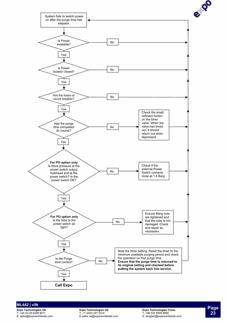
For PO option only Is there pressure at the
power switch output bulkhead and at the power switch? Is the power switch OK?
Is the Purge time correct?
System fails to switch power on after the purge time has
elapsed.
Call Expo
Has the purge time completed
its course?
Is Power available?
No
Yes Check the small indicator button
on the timer valve. When the valve has timed
out, it should return out when
depressed.
No
Yes
Yes
Check if the external Power Switch contacts close at 1.4 Barg
No
Note the timer setting. Reset the timer to the minimum available purging period and check
the operation on that purge time. Ensure that the purge time is returned to its original setting and checked before putting the system back into service.
No
For PO option only Is the tube to the power switch air
tight?
Ensure fitting nuts are tightened and that the tube is not damaged. Check and repair as necessary.
No
Yes
Yes
Is Power isolator closed?
No
Yes
Yes
Are the fuses or circuit breaker?
No

Page 20
ML442 | v5kExpo Technologies UK T: +44 (0) 20 8398 8011
Expo Technologies UST: +1 (440) 247 5314
Expo Technologies ChinaT: +86 532 8906 9858
Is the Pressurized Enclosure
pressure too high?
Is there debris on the RLV disk allowing air to leak from the
valve?
Relief Valve opens
continuously or intermittently.
Call Expo
Remove the RLV cover and clean the valve
disk. If it is necessary to remove the disk and spring from the RLV, draw a line around it with a pencil to allow accurate replacement
before removal, otherwise the opening
pressure may be affected.
The Flow Control Valve (FCV) is too far open.
Adjust the FCV clockwise to reduce the
PE pressure
No
Yes
No
Yes

ML442 | v5k Page
21 Expo Technologies UK T: +44 (0) 20 8398 8011 E: [email protected]
Expo Technologies US T: +1 (440) 247 5314 E:[email protected]
Expo Technologies China T: +86 532 8906 9858 E: [email protected]
Fault Finding (LC)
Is the actual PE pressure below
the setting of the Minimum
Pressure Sensor?
Is the Leakage Compensation
Valve setting too low causing the
MiniPurge to auto-repurge?
System purges correctly but the alarm comes on at the end of purge time and the purging cycle is
repeated.
Call Expo
Increase the PE pressure by turning the Leakage Compensation
Valve anti-clockwise.
Check the PE pressure
with a manometer or gauge.
Yes
No
Yes
No
Yes

Page 22
ML442 | v5kExpo Technologies UK T: +44 (0) 20 8398 8011
Expo Technologies UST: +1 (440) 247 5314
Expo Technologies ChinaT: +86 532 8906 9858
Is the tube between the RLV tapping and flow sensor air tight?
Is the PE strong enough?
Is the Purge Flow Sensor out of calibration or
faulty?
Purging indicator will not turn "Yellow" during
Purging.
Call Expo
Is the supply pipe to the air inlet as least 12mm I.D?
Is there excessive
leakage from the PE?
Is the air supply pressure incorrect?
No
Check the air supply pressure at the inlet to the MiniPurge is stable between 4 - 8 Barg / 60 - 115 psi
Yes
Replace pipe work
No
Yes
Any significant leakage must be corrected. Check for leaks down the cables or conduit. Ensure leakage does not exceed 60 Nl/min (2 cfm)
Yes
No
No
The standard requires that the PE is tested to 1.5 times the Relief Valve opening pressure e.g. 15 mbarg for many systems. Has this been done?
No
The basic operation of the Purge Flow Sensor can be checked by unscrewing the 60mm diameter diaphragm housing and, by using a rubber pad, e.g. an eraser, block the 12mm threaded hole in the top of the valve module. The valve should operate and the indicator turn amber. If this is correct, the sensor diaphragm needs recalibrating or replacing.
Yes
Ensure fitting nuts are tightened and that the tube is not damaged. Check and repair as necessary.
No
Yes
Yes
ML442 | v5k Page
23 Expo Technologies UK T: +44 (0) 20 8398 8011 E: [email protected]
Expo Technologies US T: +1 (440) 247 5314 E:[email protected]
Expo Technologies China T: +86 532 8906 9858 E: [email protected]
For PO option only Is there pressure at the
power switch output bulkhead and at the power switch? Is the power switch OK?
Is the Purge time correct?
System fails to switch power on after the purge time has
elapsed.
Call Expo
Has the purge time completed
its course?
Is Power available?
No
Yes Check the small indicator button on the timer valve. When the valve has timed out, it should return out when depressed.
No
Yes
Yes
Check if the external Power Switch contacts close at 1.4 Barg
No
Note the timer setting. Reset the timer to the minimum available purging period and check the operation on that purge time. Ensure that the purge time is returned to its original setting and checked before putting the system back into service.
No
For PO option only Is the tube to the power switch air
tight?
Ensure fitting nuts are tightened and that the tube is not damaged. Check and repair as necessary.
No
Yes
Yes
Is Power isolator closed?
No
Yes
Yes
Are the fuses or circuit breaker?
No

Page 24
ML442 | v5kExpo Technologies UK T: +44 (0) 20 8398 8011
Expo Technologies UST: +1 (440) 247 5314
Expo Technologies ChinaT: +86 532 8906 9858
Is the Pressurized Enclosure
pressure too high?
Is there debris on the RLV disk allowing air to leak from the
valve?
Relief Valve opens
continuously or intermittently.
Call Expo
Remove the RLV cover and clean the valve
disk. If it is necessary to remove the disk and spring from the RLV, draw a line around it with a pencil to allow accurate replacement
before removal, otherwise the opening
pressure may be affected.
The Leakage
Compensation Valve (LCV) is too far open.
Adjust the LCV clockwise to reduce the
PE pressure
No
Yes
No
Yes

ML442 | v5k Page
25 Expo Technologies UK T: +44 (0) 20 8398 8011 E: [email protected]
Expo Technologies US T: +1 (440) 247 5314 E:[email protected]
Expo Technologies China T: +86 532 8906 9858 E: [email protected]
8. Approval Documents System Certificate Certificate Number MiniPurge IECEx Certificate IECEx SIR 07.0027X ATEX Certificate 01ATEX1295X INMETRO/TÜV TÜV 12.1462X FM Certificate 1X8A4.AE UL Certificate E190061 For PA Option Only Certificate Certificate Number Ex e junction box IECEx Certificate IECEx ITS 10.0003X ATEX Certificate 10ATEX37092X INMETRO/TÜV TÜV 12.1463 Ex d switches IECEx Certificate IECEx EPS 14.0092X ATEX Certificate EPS 14 ATEX 1 766 X 9. Glossary Acronym Description A&T Alarm and Trip AO Alarm Only CF Continuous Flow CU Control Unit FCV Flow Control Valve FM Factory Mutual IS Intrinsically Safe LC Leakage Compensation LCV Leakage Compensation Valve MIU MiniPurge Interface Unit PA Ex d Power and Alarm Switch Wired to Ex e terminal box PE Pressurized Enclosure PO Pneumatic Output RLV Relief Valve SAU Spark Arrestor Unit UL Underwriter Laboratories

Con
trol
led
FLA
TNES
S T
O B
E L
ES
S T
HA
N 0
.4m
m O
VER
AN
Y 100m
m L
EN
GTH
23/0
6/20
10
TOLE
RA
NC
ES
MA
TER
IAL
UN
SPE
CIF
IED
PRO
JEC
TIO
N3r
d A
NG
LED
O N
OT
SC
ALE
Exp
o T
ech
no
log
ies L
imit
ed
JOB
No:
FIN
ISH
TITL
E
CU
STO
MER
:
SH
EET
No.
OF
1
DIM
EN
SIO
NS
IN
mm
UN
ITE
D K
ING
DO
M
DR
AW
ING
No.
SC
ALE
SU
RR
EY
K
T7
0R
H
BRD
from
Exp
o Te
chno
logi
es L
imited
, ne
ithe
r ar
e th
ey t
o be
use
d in
any
way
aga
inst
our
inte
rest
s.an
d ar
e re
turn
able
upo
n re
ques
t.
They
are
not
to
be c
opie
d or
com
mun
icat
ed in
par
t or
in w
hole
witho
ut w
ritt
en c
onse
nt
The
cont
ents
of
this
dra
win
g /
docu
men
t ar
e C
opyr
ight
© E
xpo
Tech
nolo
gies
Lim
ited
. T
hey
are
to b
e tr
eate
d as
con
fiden
tial
2 D
EC
PLA
CE ±
0.1
MIN
IPU
RG
E X L
C S
EQU
ENC
E D
IAG
RAM
XBR
-7TD
0-04
0
1:1 1
REV
: 01D
RAW
ING
STA
TUS:
APP
'DC
HK
'DD
R'W
N
JP
dBPS
C
NO
DEC
PLA
CE ±
0.5
1 D
EC
PLA
CE ±
0.2
DRAW
N D
ATE
:
EXPO
CET
IFIC
ATI
ON
DRAW
ING
EP9
9-2-
3
Opt
iona
l ope
ratio
n (U
ser
deci
sion
)
Aut
omat
ic o
pera
tion
by
the
syst
em
Key
to
func
tions
Man
ual o
pera
tion
by t
he u
ser
THIS
DRAW
ING
IS R
EFER
ENCED
TO
"Pur
ging
" In
dica
tor
Act
ion
take
n on
pre
ssur
e fa
ilure
Ala
rm a
nd d
elay
ed t
rip
Pow
er t
urne
d of
f au
tom
atic
ally
with
out
dela
y"P
ress
uriz
ed"
sign
al a
bsen
t i.e
. "A
larm
" O
Nin
clud
e:-
Ala
rm a
nd/o
r Tr
ip
Red
= P
ress
ure
Low
Low
Pre
ssur
e se
nsor
tur
ns o
ff
Encl
osur
e pr
essu
re fal
ls b
elow
the
min
imum
Encl
osur
e do
or o
pene
d, o
r ex
cess
ive
leak
age
Pres
suri
zing
air
or
iner
t ga
s tu
rned
off
Purg
e tim
er r
eset
s
Pow
er o
n -
Nor
mal
ope
ratio
n
Leak
age
Com
pens
atio
n st
arts
Purg
e flo
w c
ease
s; R
elie
f Val
ve c
lose
s
PRES
SU
RIZ
ED I
ND
ICATO
R
Purg
e flo
w fal
ls b
elow
min
imum
"Pur
ge C
ompl
ete"
sig
nal t
o el
ectr
ical
Pow
er S
witc
h
Purg
e va
lve
clos
es;
Pow
er S
w.
sign
al O
N
Purg
e tim
er t
imes
out
No
Yes
Out
let
flow
stil
l abo
ve t
he m
inim
um?
Purg
e tim
er s
tart
s au
tom
atic
ally
Purg
ing
Indi
cato
r tu
rns
Bla
ck a
s
depe
nds
upon
the
use
r. A
ctio
ns
Bla
ck =
Pur
ge flo
w t
oo lo
w
Purg
e Fl
ow S
enso
r tu
rns
on
Yes
No
Purg
e O
utle
t flo
w a
bove
the
min
imum
?
Rel
ief Val
ve o
pens
Pur
ge flo
w s
tart
s"P
ress
uriz
ed"
sign
al t
o re
mot
e al
arm
sw
itch
Am
ber
= P
urge
flo
w O
K
Gre
en =
Pre
ssur
e O
KLo
w P
ress
ure
sens
or t
urns
on
No
Yes
Is t
he P
E pr
essu
re a
bove
the
min
imum
?
Air
ent
ers
the
PE
PRES
SU
RIZ
ED I
ND
ICATO
R
Red
= P
ress
ure
Low
"Pre
ssur
ized
" si
gnal
abs
ent
i.e.
"Ala
rm"
ON
Turn
Pre
ssur
izin
g ai
r or
iner
t ga
s on
Pres
suri
zed
Encl
osur
e do
or c
lose
dPR
ESSU
RIZ
ED I
ND
ICATO
R
REV
.M
OD
NUM
BER
APP
ROV
ED D
ATE
APP
ROV
ED
01D
RAW
N23
/06/
2010
JPd
B

flow
abo
ve t
he m
inim
um s
peci
fied?
Air
ent
ers
the
PE
PRES
SU
RIZ
ED I
ND
ICATO
R
"Pre
ssur
ized
/Flo
w"
sign
al a
bsen
t i.e
. "A
larm
" O
NTu
rn P
ress
uriz
ing
air
or in
ert
gas
on
EXPO
CER
TIFI
CATI
ON
DRAW
ING
EP9
9-2-
4
"Pre
ssur
ized
/Flo
w"
sign
al t
o re
mot
e al
arm
sw
itch
Pres
suri
zed
Encl
osur
e do
or c
lose
d
THIS
DRAW
ING
IS R
EFER
ENC
ED T
O
Purg
e flo
w c
ease
s; R
elie
f Val
ve c
lose
s
Act
ion
take
n on
Pre
ssur
e/Fl
ow
Trip
Ala
rm a
nd d
elay
ed t
rip
Poss
ible
"Act
ion
on P
ress
ure/
Flow
G
reen
at
"Pur
ge C
ompl
ete"
"Pur
ge C
ompl
ete"
sig
nal t
o el
ectr
ical
Pow
er S
witc
h
Opt
iona
l ope
ratio
n (U
ser
deci
sion
)
failu
re d
epen
ds u
pon
the
user
. Act
ions
incl
ude:
- Ala
rm a
nd/o
r
Failu
re"
(use
r de
cisi
on)
Aut
omat
ic o
pera
tion
by t
he s
yste
m
Key
to
func
tions
Man
ual o
pera
tion
by t
he u
ser
Pow
er O
n In
dica
tor
turn
s
with
/with
out
dela
y"P
ress
uriz
ed/F
low
" si
gnal
abs
ent
i.e.
"Ala
rm"
ON
Pres
suri
zed/
Flow
Ind
icat
or
fall
belo
w t
he m
inim
um
Encl
osur
e do
or o
pene
d, o
r ex
cess
ive
leak
age
Pres
suri
zing
air
or
iner
t ga
s tu
rned
off
Purg
e tim
er r
eset
s
Pow
er o
n -
Nor
mal
ope
ratio
n
Out
let
flow
still
abov
e th
e m
inim
um?
Con
tinuo
us F
low
/ D
ilutio
n Fl
ow s
tart
s
No
Yes
Pow
er o
n
Pow
er S
w.
sign
al O
N
Purg
e tim
er t
imes
out
Yes
Pow
er t
urne
d of
f au
tom
atic
ally
Red
= P
ress
ure/
Flow
Low
Low
Pre
ssur
e/Fl
ow s
enso
r tu
rns
off
Encl
osur
e pr
essu
re o
r Fl
ow
Gre
en =
Pre
ssur
e/Fl
ow O
K
No
Purg
e O
utle
t flo
w a
bove
the
min
imum
?
Purg
e tim
er s
tart
s au
tom
atic
ally
Low
Pre
ssur
e se
nsor
tur
ns o
n
No
Yes
Encl
osur
e pr
essu
re a
nd t
he p
urge
out
let
Red
= P
ress
ure
Low
PRES
SU
RIZ
ED I
ND
ICATO
R
REV
.M
OD
NUM
BER
APP
ROV
ED D
ATE
APP
ROV
ED
01D
RAW
N23
/06/
2010
JPd
B
REV
:
PSC
1
SU
RR
EY
K
T7
0R
H
JPdB
23/0
6/20
10
and
are
retu
rnab
le u
pon
requ
est.
Th
ey a
re n
ot t
o be
cop
ied
or c
omm
unic
ated
in p
art
or in
who
le w
itho
ut w
ritt
en c
onse
nt
TOLE
RA
NC
ES
MATE
RIA
L
3rd
AN
GLE
DO
NO
T S
CA
LE
Exp
o T
ech
no
log
ies L
imit
ed
JOB N
o:
FIN
ISH
TITL
E
CU
STO
MER
:
FLA
TNES
S T
O B
E LE
SS
TH
AN
0.4
mm
OV
ER A
NY
100m
m L
ENG
TH
UN
SPE
CIF
IED
PRO
JEC
TIO
ND
IMEN
SIO
NS
IN
mm
BR
D
DR'W
N
from
Exp
o Te
chno
logi
es L
imited
, ne
ithe
r ar
e th
ey t
o be
use
d in
any
way
aga
inst
our
inte
rest
s.
Con
trol
led
UN
ITE
D K
ING
DO
M
DR
AW
ING
No.
SCALE
The
cont
ents
of th
is d
raw
ing
/ do
cum
ent
are
Cop
yrig
ht ©
Exp
o Te
chno
logi
es L
imited
. T
hey
are
to b
e tr
eate
d as
con
fiden
tial
2 D
EC P
LAC
E ±
0.1
SH
EET
No.
O
F
XBR-7
TD0-
041
MIN
IPU
RG
E X C
F SEQ
UEN
CE
DIA
GRAM
1:1
01D
RAW
ING
STA
TUS:
APP
'DCH
K'D
1
NO
DEC
PLA
CE
±0.5
1 D
EC P
LAC
E ±
0.2
DR
AW
N D
ATE
:
BS EN50016:1995 (2nd edition)[EEx p] II Sira Certificate Ex99E1002U
EEx p II SCS Certificate Ex 94C1052UEN50 016:1977 (BS 5501 pt 3)
PRESSURISE
PRESSURIZED(GREEN)
(VERT) (GELB)VORSPÜLUNGEN BALAYAGE
(GRÜN)DRUCK OK
(JAUNE)
(YELLOW)PURGING
ALARM(RED)
ALARM(ROT) (ROUGE)
ALARME
ORIFICE PLATEAND CIRCLIPSEE NOTE
GASKET
SPARK ARRESTORBODY
PURGE OUTLETDO NOT OBSTRUCT
HOUSING
GASKET
2
FOR LC SYSTEMS ONLY
FLATNESS TO
BE LESS THAN
0.4mm
OVER
ANY 100m
m LEN
GTH
UN
SP
EC
IFIED
TOLE
RA
NC
ES
MA
TER
IAL
DR
AW
ING
STA
TUS
:A
PP
RO
VE
D:
MO
D. N
o:D
ATE:
ISSUE:
3rd ANG
LEP
RO
JEC
TION
DIM
ENSIO
NS IN
mm
DO
NO
T SCALE
Expo Technologies Limited
JOB N
o:
FINISH
TITLE
CU
STO
ME
R:
SH
EE
T No.
OF
SUR
REY KT7 0R
HU
NITE
D K
ING
DO
M
DR
AW
ING
No.
SCALE
The contents of this drawing / docum
ent are Copyright
Expo Technologies Limited. They are to be treated as confidential and are returnable
upon request. They are not to be copied or comm
unicated in part or in whole w
ithout written consent from
Expo Technologies Limited, neither
are they to be used in any way against our interests.
NO
DEC
PLACE ±0.5
1 DEC
PLACE ±0.2
2 DEC
PLACE ±0.1
CERT RELATEDMJF
DRAWN
1
11
STAINLESS STEEL3
CF OPTION
SAU 25 SPARK ARRESTOR(CF OPTION ONLY)
D.P. LO 6mm OR M5 (10-32 UNF) FITTING SUPPLIED
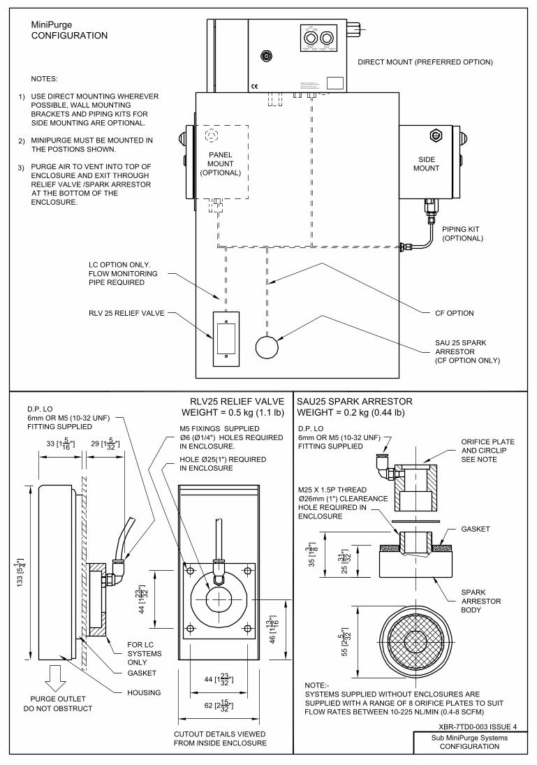
MiniPurge CONFIGURATION
PIPING KIT (OPTIONAL)
DIRECT MOUNT (PREFERRED OPTION)
PANEL MOUNT
(OPTIONAL)
SIDE MOUNT
PRINT WINDOW ON VIEWPORT FULL SIZE
NOTE:- SYSTEMS SUPPLIED WITHOUT ENCLOSURES ARE SUPPLIED WITH A RANGE OF 8 ORIFICE PLATES TO SUIT FLOW RATES BETWEEN 10-225 NL/MIN (0.4-8 SCFM)
XBR-7TD0-003 ISSUE 4Sub MiniPurge Systems
CONFIGURATION
NOTES:
USE DIRECT MOUNTING WHEREVER POSSIBLE, WALL MOUNTING BRACKETS AND PIPING KITS FOR SIDE MOUNTING ARE OPTIONAL.
MINIPURGE MUST BE MOUNTED IN THE POSTIONS SHOWN.
PURGE AIR TO VENT INTO TOP OF ENCLOSURE AND EXIT THROUGH RELIEF VALVE /SPARK ARRESTOR AT THE BOTTOM OF THE ENCLOSURE.
1)
2)
3)
33 [1 516"] 29 [1 5
32"]
M5 FIXINGS SUPPLIEDØ6 (Ø1/4") HOLES REQUIRED IN ENCLOSURE.
46 [1
13 16"]
44 [12332"]
62 [21532"]
44 [1
23 32"]
HOLE Ø25(1") REQUIRED IN ENCLOSURE
55 [2
5 32"]
25 [31 32
"]
35 [1
3 8"]
LC OPTION ONLY.FLOW MONITORING PIPE REQUIRED
RLV 25 RELIEF VALVE
SAU25 SPARK ARRESTOR WEIGHT = 0.2 kg (0.44 lb)
RLV25 RELIEF VALVE WEIGHT = 0.5 kg (1.1 lb)
CUTOUT DETAILS VIEWED FROM INSIDE ENCLOSURE
M25 X 1.5P THREADØ26mm (1") CLEAREANCE HOLE REQUIRED IN ENCLOSURE
D.P. LO 6mm OR M5 (10-32 UNF) FITTING SUPPLIED
133
[51 4"]


ww
w.e
xpow
orld
wid
e.co
m
Min
iPur
ge
FLA
TNE
SS
TO
BE
LE
SS
TH
AN
0.4
mm
OV
ER
AN
Y 1
00m
m L
EN
GTH
UN
SP
EC
IFIE
DTO
LER
AN
CE
S
MA
TER
IAL
DR
AW
ING
STA
TUS
:AP
PRO
VED
:
MO
D. N
o:
DAT
E:
ISSU
E:
3rd
AN
GLE
PRO
JEC
TIO
N
DIM
EN
SIO
NS
IN m
m
DO
NO
T S
CA
LE
Expo
Tec
hnol
ogie
s Li
mite
d
JOB
No:
FIN
ISH
TITL
E
CU
STO
ME
R:
SH
EE
T N
o.O
F
SU
RR
EY
KT7
0R
HU
NIT
ED
KIN
GD
OM
DR
AW
ING
No.
SCAL
E
The
cont
ents
of t
his
draw
ing
/ doc
umen
t are
Cop
yrig
ht
E
xpo
Tech
nolo
gies
Lim
ited.
The
y ar
e to
be
treat
ed a
s co
nfid
entia
l and
are
retu
rnab
leup
on re
ques
t. T
hey
are
not t
o be
cop
ied
or c
omm
unic
ated
in p
art o
r in
who
le w
ithou
t writ
ten
cons
ent f
rom
Exp
o Te
chno
logi
es L
imite
d, n
eith
erar
e th
ey to
be
used
in a
ny w
ay a
gain
st o
ur in
tere
sts.
NO
DEC
PLA
CE
±0.5
1 D
EC
PLA
CE
±0.
22
DE
C P
LAC
E ±
0.1
NON
CERT
IFIED
MJF
DRAW
N1
13
STAINL
ESS
STEE
L
NROB
150
[5.9
1"]
MO
UN
TIN
G B
AR P
ITC
H =
180
[7.0
9"]
102
[4.0
2"]
180 [7.09"]
155 [6.10"]
AIR
SU
PP
LY 4
- M
AX
8 b
arg
[60-
115
psi]
1/2"
NPT
F
PU
RG
E O
UTL
ET
1/2"
NP
TF
D.P
. HI /
EN
CLO
SU
RE
PR
ES
SU
RE
1/8
" NP
TF
D.P
. LO
/ R
LV O
R S
AU
CO
NN
EC
TIO
N 1
/8" N
PTF
129
[5.0
8"]
RE
MO
VA
BLE
CO
VE
R
HO
LE S
UIT
AB
LE F
OR
GLA
ND
M20
OR
1/2
" NP
T
MOUNTING BAR PITCH = 210 [8.27"]
MO
UN
TIN
G B
AR(S
PE
CIA
L O
PTI
ON
ON
LY)
12
PA
. OP
TIO
N
CU
STO
ME
R T
O
SIT
E A
ND
DR
ILL
INP
UT
GLA
ND
H
OLE
37[1
.46"
]
35[1.38"]
65 [2.56"]
45 [1
.77"
]
PO
WE
R IN
TER
LOC
K
SIG
NA
L1/
8" N
PTF
PA
SS
IVE
ALA
RM
/ PR
ES
SU
RIZ
ED
S
IGN
AL
1/8"
NPT
F
41[1.61"]
96 [3
.78"
]
HO
LE S
UIT
AB
LE
FOR
GLA
ND
M20
OR
1/
2" N
PT
PO
. OP
TIO
N
IS. O
PTI
ON
NO
TES
MIN
IPU
RG
E M
US
T B
E M
OU
NTE
D W
ITH
PU
RG
E O
UTL
ET
FITT
ING
IN
VE
RTI
CA
L P
LAN
E P
OIN
TIN
G D
OW
N.
AP
PR
OX
IMA
TE W
EIG
HT:
5.5
kg
[12.
1 P
OU
ND
S].
EQ
UIV
ALE
NT
IMP
ER
IAL
DIM
EN
SIO
NS
SH
OW
N IN
BR
AC
KE
TS.
RE
FER
TO
DR
G X
SD
-7TD
0-00
1 FO
R M
OU
NTI
NG
DE
TAIL
S.
HO
LE Ø
7.5
[Ø0.
30"]
FOR
M6
OR
1/4"
FIX
ING
155
[6.1
0"]
185
[7.2
8"]
120
[4.7
2"]
65 [2
.56"
]
5 [0.20"]
75 [2.95"] 75 [2.95"]
90 [3.54"]LEA
KA
GE
C
OM
PE
NS
ATI
ON
(L
C)
CO
NTI
NU
OU
S
FLO
W (C
F)
CO
NTI
NU
OU
S
FLO
W A
FTE
R
HIG
H P
UR
GE
(C
FHP)
ALAR
MIN
DIC
ATO
R 1
ALARMRED RED RED
PRESSURIZEDGREE
N
GREEN
GREEN
PU
RG
EIN
DIC
ATO
R 2
PURGINGYE
LLOW
REDYE
LLOW
PURGE COMPLETE
BLAC
KGREE
NBL
ACK
(LC
OP
TIO
N O
NLY
)
IND
ICA
TOR
S
35 [1
.30"
] AP
PR
OX
.
35 [1.30"]APPROX.
8 [0.31"]APPROX.
8 [0
.31"
] AP
PR
OX
. 1. 2. 3.
240
[9.4
5"]
343
5313
/09/
07 J
PdB
443
8521
/12/
07JP
dB
546
572/
4/09
JPdB

76
15
2614
19
17161
213
187
3
MIN
IMU
M P
RE
SS
UR
E S
EN
SO
R
PU
RG
E C
OM
PLE
TE "O
R" G
ATE
LEA
KA
GE
CO
MP
EN
SA
TIO
N V
ALV
E
PU
RG
E B
OO
ST
VA
LVE
PLU
G 4
mm
PU
RG
E C
OM
PLE
TE V
ALV
E (B
ELO
W IT
EM
17)
LO
GIC
AIR
SU
PP
LY R
EG
ULA
TOR
IN L
INE
RE
STR
ICTO
R
BLA
CK
CO
LLA
R (P
LUG
GE
D)
IND
ICA
TOR
, "A
LAR
M/P
RE
SS
UR
IZE
D"
IND
ICA
TOR
, "P
UR
GIN
G"
PU
RG
E F
LOW
SE
NS
OR
2 9 137 83
GA
UG
E, L
OG
IC A
IR S
UP
PLY
1
MA
IN A
IR S
UP
PLY
FIL
TER
, MA
NU
AL
DR
AIN
15
TIM
ER
VA
LVE
19 22
26
16 17 1814
ALA
RM
ON
LY P
US
H-IN
FIT
TIN
G
ALA
RM
AN
D T
RIP
PU
SH
-IN F
ITTI
NG
PU
RG
E T
IME
SE
LEC
TOR
"AC
TIO
N O
N A
LAR
M" O
PTI
ON
PIP
E
34 763533
89
3335
34
EN
CLO
SU
RE
P
RE
SS
UR
E
TES
T P
OIN
T
TO R
ES
ER
VO
IRS
PU
RG
E T
IME
SE
LEC
TOR
TIM
ER
P
INC
H
VA
LVE
S
PU
SH
-IN P
LUG
ALA
RM
ON
LYA
LAR
M A
ND
TR
IP
DO
OR
INTE
RN
AL
AO
CA&
TA&
TA
OC
2622
LC L
EA
KA
GE
CO
MP
EN
SA
TIO
N S
HO
WN
(ITE
MS
IN D
OTT
ED
RE
MO
VE
D F
OR
CF)
DR
AW
ING
STA
TUS
:AP
PRO
VED
:
MO
D. N
o:
DAT
E:
ISSU
E:M
ATE
RIA
L
FIN
ISH
SU
RR
EY
KT7
0R
HU
NIT
ED
KIN
GD
OM
Expo
Tec
hnol
ogie
s Li
mite
d
JOB
No:
TITL
E
CU
STO
ME
R:
DR
AW
ING
No.
SH
EE
T N
o.
SCAL
E
OF
NO
DEC
PLA
CE
±0.5
1 D
EC
PLA
CE
±0.
22
DE
C P
LAC
E ±
0.1
FLA
TNE
SS
TO
BE
LE
SS
TH
AN
0.4
mm
OV
ER
AN
Y 1
00m
m L
EN
GTH
3rd
AN
GLE
PRO
JEC
TIO
N
DIM
EN
SIO
NS
IN m
m
DO
NO
T S
CA
LEU
NS
PE
CIF
IED
TOLE
RA
NC
ES
The
cont
ents
of t
his
draw
ing
/ doc
umen
t are
Cop
yrig
ht
E
xpo
Tech
nolo
gies
Lim
ited.
The
y ar
e to
be
treat
ed a
s co
nfid
entia
l and
are
retu
rnab
leup
on re
ques
t. T
hey
are
not t
o be
cop
ied
or c
omm
unic
ated
in p
art o
r in
who
le w
ithou
t writ
ten
cons
ent f
rom
Exp
o Te
chno
logi
es L
imite
d, n
eith
erar
e th
ey to
be
used
in a
ny w
ay a
gain
st o
ur in
tere
sts.
DRAW
N
MJF
NON
CERT
IFIED
1
23
443
8521
/12/
07JP
dB
546
572/
4/09
JPdB
343
5313
/09/
07 J
PdB

PA
OP
TIO
NPO
OPT
ION
IS O
PTI
ON
Ex
d S
WIT
CH
WIR
ED
TO
ALA
RM
TE
RM
INA
LS IN
PA
BO
X
Ex
d S
WIT
CH
WIR
ED
TO
PO
WE
R
TER
MIN
ALS
IN P
A B
OX
PA B
OX
CLE
AR
4m
m P
IPE
TO
PA
SS
IVE
A
LAR
M/P
RE
SS
UR
IZE
D S
IGN
AL
1/8"
NP
TF C
ON
NE
CTO
R
BLU
E 4
mm
PIP
E T
O P
OW
ER
IN
TER
LOC
K 1
/8" N
PTF
CO
NN
EC
TOR
TER
MIN
ALS
FO
R C
ON
NE
CTI
NG
I.S
. C
IRC
UIT
S V
IA M
20 O
R 1
/2" N
PT
CA
BLE
E
NTR
Y O
N L
HS
OR
BO
TTO
M
NO
TE:
LC V
ER
SIO
N S
HO
WN
. (IT
EM
S IN
DO
TTE
D R
EM
OV
ED
FO
R C
F)
FLO
W
MIN
FLO
W
MIN
FLO
W
MIN
DR
AW
ING
STA
TUS
:AP
PRO
VED
:
MO
D. N
o:
DAT
E:
ISSU
E:M
ATE
RIA
L
FIN
ISH
SU
RR
EY
KT7
0R
HU
NIT
ED
KIN
GD
OM
Expo
Tec
hnol
ogie
s Li
mite
d
JOB
No:
TITL
E
CU
STO
ME
R:
DR
AW
ING
No.
SH
EE
T N
o.
SCAL
E
OF
NO
DEC
PLA
CE
±0.5
1 D
EC
PLA
CE
±0.
22
DE
C P
LAC
E ±
0.1
FLA
TNE
SS
TO
BE
LE
SS
TH
AN
0.4
mm
OV
ER
AN
Y 1
00m
m L
EN
GTH
3rd
AN
GLE
PRO
JEC
TIO
N
DIM
EN
SIO
NS
IN m
m
DO
NO
T S
CA
LEU
NS
PE
CIF
IED
TOLE
RA
NC
ES
The
cont
ents
of t
his
draw
ing
/ doc
umen
t are
Cop
yrig
ht
E
xpo
Tech
nolo
gies
Lim
ited.
The
y ar
e to
be
treat
ed a
s co
nfid
entia
l and
are
retu
rnab
leup
on re
ques
t. T
hey
are
not t
o be
cop
ied
or c
omm
unic
ated
in p
art o
r in
who
le w
ithou
t writ
ten
cons
ent f
rom
Exp
o Te
chno
logi
es L
imite
d, n
eith
erar
e th
ey to
be
used
in a
ny w
ay a
gain
st o
ur in
tere
sts.
DRAW
N
MJF
NON
CERT
IFIED
1
33
443
8521
/12/
07JP
dB
546
572/
4/09
JPdB
343
5313
/09/
07 J
PdB

rof noitc ennoC sutarappA elpmiS
)tcatnoc yrd( hctiwS edirrev
O launaM
0 = iL ,0
= iC ,A0 = xa
mI ,V0 = xa
mV
V03 = xa
mVA
m001 = xa
mI0
= iL 0 = iC
Am
10
1 si V
03
= ka
ep
V rof ,.
S.I rof x
amI
de tti
mre
p B ,
A sp
uor
G sa
G ro
F 6
.A
m0
53 si .
S.I rof x
amI
V2.
91
= ka
ep
V hti
w B ,
A p
uor
G sa
G ro
F :ylevit
anr
etlA
+
b1
giF
dn
a a
1 gi
F ht
ob r
of set
oN
stlov
05
2 n
aht
ero
m et
are
ne
g ro
esu t
on
dlu
ohs s
utar
ap
pa
det
aicoss
a ot
detc
en
noc t
ne
mpi
uq
e lacirtc
elE
1
)0
7 A
PF
N/IS
NA(
ed
oC l
acirtcel
E la
noit
aN
eht
dn
a sn
oitcurts
ni s 'rer
utcaf
un
am
eht
htiw
ecn
adr
occa
ni e
b lla
hs n
oitall
at snI
2
)sn
oitac
oL s
uo
draz
aH I ss
alC
ni sm
etsyS t
ne
mur ts
nI SI f
o n
oitall
atsnI( ,
6.2
1P
R A
SI/IS
NA
ees
noit
allats
nI n
o ec
na
diu
g ro
F 3
xa
mV
na
ht ssel si s
utar
ap
pa
det
aicoss
a fo t
V ro c
oV
4
xa
mI n
aht ss
el si sut
ara
pp
a d
etaic
ossa f
o tI ro csI
sut
ara
pp
a d
etaic
ossa
eht f
o a
C n
aht ss
el si g
nilb
ac g
nitce
nn
ocret
ni fo
ecn
atica
pac s
ulp i
C
sut
ara
pp
a d
etaic
ossa
eht f
o a
L n
aht ss
el si g
nilb
ac g
nitce
nn
ocret
ni fo
ecn
atcu
dni s
ulp i
L
Ju
02 r
o W
m5
2 ,A
1.0 ,
V2.
1 n
aht
ero
m er
ot s ro
etar
en
eg t
on lli
w ta
ht eciv
ed
a si "sut
ara
pp
A el
pmi
S" 5
)sut
ara
pp
a d
etcet
orp yl
bati
us ro(
.S.I
ecafr
etnI
tin
U
ylp
pus r
ew
oP
.srotc
atn
oc re
wo
p ron
oitac
oL s
uo
draz
aH-
no
N
syal
er ot .
g.e st
upt
uO
)sut
ara
pp
a d
etcet
orp yl
bati
us ro(
.S.I
ecafr
etnI
tin
U
ylp
pus r
ew
oP
.srotc
atn
oc re
wo
p ron
oitac
oL s
uo
draz
aH-
no
N
noit
aco
L su
odr
aza
H
V0
3 = x
am
VA
m0
01
= xa
mI
syal
er ot .
g.e st
upt
uO
tiucric
ecafr
etni l
en
na
hc el
gni
S a
1 gi
F
tiucric
mral
A n
oitazir
usser
P "Z" r
o "Y" .
g.e
lort
no
C re
wo
P &
mral
A n
oitazir
usser
p "X" .
g.e
tiucric
ecafr
etni l
en
na
hc-itlu
M b
1 gi
F
0 = i
L 0
= iC
*/8
01
S #t
P B
CP
)n
oitar
ugif
noc
= *(
ecive
ds
utar
ap
pa
elp
miS
G d
na
F ,E ,
D ,C ,
B ,A s
pu
orG
2 ro
1 viD ,II r
o I ssal
C
SI/ e
do
C n
oitp
O :e
gru
Pini
MSI/
ed
oC
noit
pO :
egr
uPi
niM
noit
aco
L su
odr
aza
H
2 ro
1 viD ,II r
o I ssal
CG
dn
a F ,
E ,D ,
C ,B ,
A sp
uor
G
1 2 0 M
deti
miL
sei
gol
on
hc
eT
op
xE
:RE
MOT
SU
C.o
N TEEH
SF
O
ELA
CS
HR
0 7
TK
YE
RR
US
MO
DG
NIK
DE
TIN
U
ELG
NA dr3
NOIT
CEJO
RP
:oN
BOJ
ELTIT.o
N G
NIW
AR
D
mm
NI S
NOI
SNE
MID
ELA
CS T
ON
OD
laitnedifnoc sa detaert eb ot era yehT .detimiL seigolonhceT opxE
© thgirypoC era tne
mucod / gniward siht fo stnetnoc ehT
tnesnoc nettirw tuohti
w elohw ni ro trap ni detacinu
mmoc ro deipoc eb ot ton era yehT .tseuqer nopu elbanruter era dna
.stseretni ruo tsniaga yaw yna ni desu eb ot yeht era rehtien ,deti
miL seigolonhceT opxE morf
11
OMA
OMA
OMA
7002/70/3160
D'PPAD'
KH
CN
W'R
D
deifitreC
:SUTATS
GNI
WAR
D
:ETAD
NWA
RD
:VER
STN
NOIT
ACIFIT
RE
C A
SI SI
HT
.TN
EM
UC
OD
D
ESI
RO
HTU
AN
U Y
NA
SE
TA
DILA
VNI
EG
NA
HC
.LA
VO
RP
PA
'SI' N
OITPO E
GRUPI
NIM
11-2-08PE
40334
7002/7/31CL
M
506705
0102/11/10O
MA
607925
1102/70/02O
MA
.VER
REBMU
N D
OM
ETA
D DEV
ORPPA
DEVORPP
A
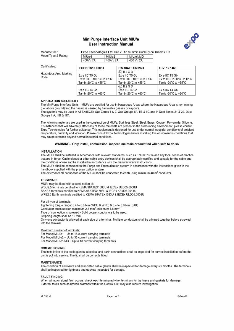
ML358 v7 Page 1 of 1 18-Feb-16
MiniPurge Interface Unit MIU/eUser Instruction Manual
Manufacturer: Expo Technologies Ltd, Unit 2 The Summit, Sunbury on Thames. UK.Model Type & Rating:
Certificates:
Hazardous Area Marking Code:
APPLICATION SUITABILITYThe MiniPurge Interface Units – MIU/e are certified for use in Hazardous Areas where the Hazardous Area is non-mining (i.e. above ground) and the hazard is caused by flammable gasses or vapours.The systems may be used in ATEX/IECEx Gas Zones 1 & 2, Gas Groups IIA, IIB & IIC and in Dust Zones 21 & 22, Dust Groups IIIA, IIIB & IIIC.
The following materials are used in the construction of MIU/e: Stainless Steel, Steel, Brass, Copper, Polyamide, Silicone.If substances that will adversely affect any of these materials are present in the surrounding environment, please consult Expo Technologies for further guidance. This equipment is designed for use under normal industrial conditions of ambient temperature, humidity and vibration. Please consult Expo Technologies before installing this equipment in conditions that may cause stresses beyond normal industrial conditions.
WARNING - Only install, commission, inspect, maintain or fault find when safe to do so.
INSTALLATIONThe MIU/e shall be installed in accordance with relevant standards, such as EN 60079-14 and any local codes of practice that are in force. Cable glands or other cable entry devices shall be appropriately certified and suitable for the cable and the conditions of use and be installed in accordance with the manufacturer’s instructions.The MIU/e shall be connected to the Purge and Pressurization system in accordance with the instructions given in the handbook supplied with the pressurization system.The external earth connection of the MIU/e shall be connected to earth using minimum 4mm2 conductor.
TERMINALSMIU/e may be fitted with a combination of:WDU2.5 terminals certified to KEMA 98ATEX1683U & IECEx ULD05.0008USAK2.5 terminals certified to KEMA 98ATEX1798U & IECEx KEM06.0014UWPE2.5 Earth terminals certified to KEMA 98ATEX1683U & IECEx ULD05.0008U
For all type of terminals:Tightening torque range: 0.4 to 0.8 Nm (WDU & WPE) & 0.4 to 0.6 Nm (SAK)Conductor cross section maximum 2.5 mm2, minimum 1.5 mm2
Type of connection is screwed - Solid copper conductors to be used.Stripping length shall be 10 mm.Only one conductor is allowed at each side of a terminal. Multiple conductors shall be crimped together before screwed into the terminal.
Maximum number of terminals:For Model MIU/e1 – Up to 18 current carrying terminalsFor Model MIU/e2 – Up to 33 current carrying terminalsFor Model MIU/e1/MO – Up to 13 current carrying terminals
COMMISSIONINGThe installation of the cable glands, electrical and earth connections shall be inspected for correct installation before theunit is put into service. The lid shall be correctly fitted.
MAINTENANCEThe condition of enclosure and associated cable glands shall be inspected for damage every six months. The terminalsshall be inspected for tightness and gaskets inspected for damage.
FAULT FINDINGWhen wiring or signal fault occurs, check each terminated wire, terminals for tightness and gaskets for damage.External faults such as broken switches within the Control Unit may also require investigation.
MIU/e1 MIU/e2 MIU/e1/MO400V / 7A 400V / 7A 400 V / 2A
IECEx ITS10.0003X ITS 10ATEX37092X TUV 12.1463
Ex e IIC T5 GbEx tb IIIC T100°C Db IP66Tamb -20°C to +55°C
II 2 G DEx e IIC T5 Gb Ex tb IIIC T100°C Db IP66Tamb -20°C to +55°C
Ex e IIC T5 GbEx tb IIIC T100ºC Db IP66Tamb -20°C to +55°C
Ex e IIC T4 GbTamb -20ºC to +60ºC
II 2 G DEx e IIC T4 Gb Tamb -20°C to +60°C
Ex e IIC T4 GbTamb -20°C to +60°C

S:\Files\QA\CERTS\C-OF-C\Minipurge CE SC004 Issue9.doc
EU-Declaration of Conformity
With European Directives
Issued under the sole responsibility of
Expo Technologies Ltd Unit 2, The Summit, Hanworth Road
Sunbury on Thames TW16 5DB, UK
This is to declare that “Purge Controllers: Sub-MiniPurge, MiniPurge, Super-MiniPurge, Super-MiniPurge 1800/3500/7000/7000X”
are manufactured in conformity with the following European Directives and standards:
Electromagnetic Compatibility Directive 2014/30/EU MiniPurge Systems with a /PO suffix in the type number are non-electrical and are outside the scope of the EMC Directive. MiniPurge Systems with suffices /PA or /IS incorporate one or more volt-free (“dry”) contacts which work in circuits specified by others. In normal operation these circuits are “benign” and no CE mark is appropriate. MiniPurge Systems with Electronic Timer (Option /ET) are designed to conform to the EMC Directive, in compliance with EN 61000-6-4:2007 and EN 61000-6-2:2005 (Intertek Report EM10048000). Low Voltage Directive 2014/35/EU MiniPurge Systems are intended for use in potentially explosive atmospheres (Hazardous Areas) and are therefore excluded from the Low Voltage Directive. Pressure Equipment Directive 97/23/EC MiniPurge Systems are classified as not higher than category I under Article 9 of this Directive and intended for use in potentially explosive atmospheres (Hazardous Areas) and are therefore excluded from the Pressure Equipment Directive. ATEX Directive 2014/34/EU Equipment for explosive atmospheres MiniPurge Systems are designed to conform to the ATEX Directive in fulfilment of the essential health and safety requirements set out in Annex II, and in compliance with: EN 60079-0: 2012 + A11:2013 EN 60079-2: 2014 MiniPurge Systems are certified by SIRA Certification Service, Hawarden Industrial Park, Hawarden CH5 3US, England, under EC Type-Examination Certificate SIRA 01ATEX1295X, in compliance with: EN 60079-0: 2012 EN 60079-2: 2014 According to the model, MiniPurge Systems are rated and shall be marked as follows: MiniPurge, Type X & Type Y models Group II Category 2G & 2D II 2(2) GD MiniPurge, Type Z models Group II Category 3G & 3D II 2(3) GD MiniPurge systems are manufactured under Production Quality Assurance Notification SIRA 99 ATEX M043, issued by SIRA Certification Service, Notified Body No 0518. Signed for and on behalf of Expo Technologies Ltd.,
John Paul de Beer Date 16/08/2016 Managing Director Confidential Assessment file reference SC004 JJJJJJJJJJJJJJJoJJJJJJJJJJJJJJJJJJJJJJJJJJJJJ hn Paul de


Expo Technologies USAExpo Technologies Inc.
9140 Ravenna Road Unit #3Twinsburg,
OH 440878, USAT: +1 440 247 5314F: +1 330 487 0611
Expo Technologies UKExpo Technologies Ltd.
Unit 2 The Summit, Hanworth RoadSunbury-On-Thames,
TW16 5DB, UKT: +44 20 8398 8011F: +44 20 8398 8014
Expo Technologies ChinaQingdao Expo M&E Technologies Co. Ltd
329 Huashan Er LuJimo City, Qingdao,
266200 ChinaT: +86 532 8906 9858F: +86 532 8906 9858
www.expoworldwide.com