Embed Size (px)
Citation preview

Minimum Redundancy MIMO Radar
Chun-Yang Chen and P. P. Vaidyanathan
California Institute of Technology
Electrical Engineering/DSP Lab
ISCAS 2008

Outline
Review of the background– MIMO radar and virtual array– Minimum redundancy linear array
Minimum redundancy MIMO radar– Extension of the minimum redundancy idea– Examples and simulations
Conclusion
2Chun-Yang Chen, Caltech DSP Lab | ISCAS 2008
1Review: MIMO Radar and Virtual Array
3
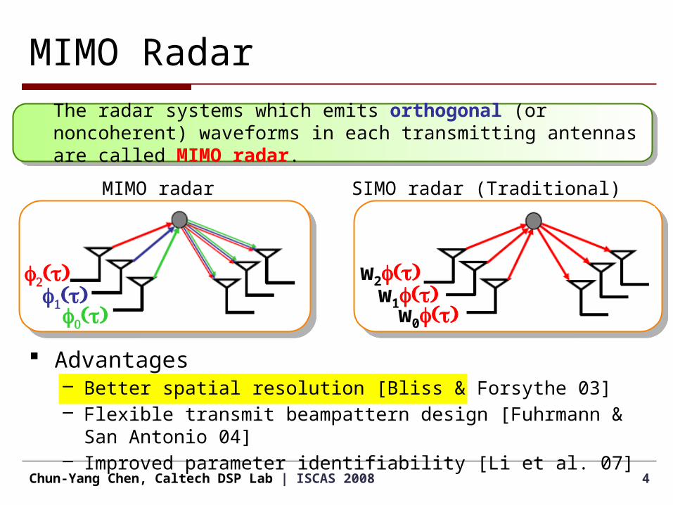
Advantages– Better spatial resolution [Bliss & Forsythe 03]– Flexible transmit beampattern design [Fuhrmann & San Antonio 04]– Improved parameter identifiability [Li et al. 07]
4Chun-Yang Chen, Caltech DSP Lab | ISCAS 2008
MIMO Radar
MIMO radar
f2( )tf1( )t
f0( )t
SIMO radar (Traditional)
The radar systems which emits orthogonal (or noncoherent) waveforms in each transmitting antennas are called MIMO radar.
w2 ( )f tw1 ( )f t
w0 ( )f t

5Chun-Yang Chen, Caltech DSP Lab | ISCAS 2008
SIMO Radar (Traditional)
Transmitter: M antenna elements
ej2p(ft-x/l)
w2 ( )f t w1 ( )f t w0 ( )f t
Transmitter emits
coherent waveforms.
Transmitter emits
coherent waveforms.
Receiver: N antenna elements
ej2p(ft-x/l)
Number of received signals: N
Number of received signals: N

6Chun-Yang Chen, Caltech DSP Lab | ISCAS 2008
MIMO Radar
ej2p(ft-x/l)
f2( )t f1( )t f0( )t
Transmitter emits
orthogonal waveforms.
Transmitter emits
orthogonal waveforms.
Transmitter: M antenna elements
ej2p(ft-x/l)
MF MF…
…
Matched filters extract the M orthogonal waveforms.Overall number of signals:
NM
Matched filters extract the M orthogonal waveforms.Overall number of signals:
NM
Receiver: N antenna elements

Virtual Array Concept
7Chun-Yang Chen, Caltech DSP Lab | ISCAS 2008
ej2p(ft-x/l)
q
xT,0=0xT,1xT,2
Receiver: N antenna elements
ej2p(ft-x/l)
q
xR,0=0xR,2
Transmitter: M antenna elements
xR,3 xR,1

Virtual Array Concept
8Chun-Yang Chen, Caltech DSP Lab | ISCAS 2008
ej2p(ft-x/l)
q
Receiver: N antenna elements
ej2p(ft-x/l)
q
Transmitter: M antenna elements
xT,0=0xT,1xT,2 xR,0=0xR,2xR,3 xR,1

))(sin2
exp( ,,, nRmTmn xxjs
Virtual Array Concept
9Chun-Yang Chen, Caltech DSP Lab | ISCAS 2008
ej2p(ft-x/l)
q
Receiver: N antenna elements
ej2p(ft-x/l)
q
Transmitter: M antenna elements
xT,0=0xT,1xT,2 xR,0=0xR,2xR,3 xR,1

))(sin2
exp( ,,, nRmTmn xxjs
Virtual Array Concept
10Chun-Yang Chen, Caltech DSP Lab | ISCAS 2008
ej2p(ft-x/l)
q
Receiver: N antenna elements
ej2p(ft-x/l)
q
Transmitter: M antenna elements
xT,0=0xT,1xT,2 xR,0=0xR,2xR,3 xR,1
11Chun-Yang Chen, Caltech DSP Lab | ISCAS 2008
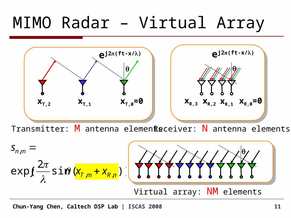
MIMO Radar – Virtual Array
Transmitter: M antenna elements Receiver: N antenna elements
Virtual array: NM elements
q
))(sin2
exp( ,,
,
nRmT
mn
xxj
s
ej2p(ft-x/l)
q
ej2p(ft-x/l)
q
xT,0=0xT,1xT,2 xR,0=0xR,2xR,3 xR,1

12Chun-Yang Chen, Caltech DSP Lab | ISCAS 2008
MIMO Radar – Virtual Array
Receiver: N elements
Virtual array: NM elements
Transmitter: M elements
+ =
[D. W. Bliss and K. W. Forsythe, 03]
The spatial resolution is the same as a receiving array with NM physical array elements.
NM degrees of freedom can be created using only N+M physical array elements.
2Review: Minimum Redundancy Linear Array
13
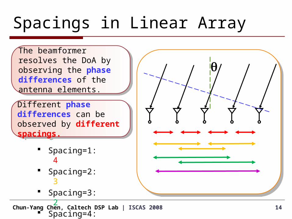
Spacings in Linear Array
14Chun-Yang Chen, Caltech DSP Lab | ISCAS 2008
q
Spacing=1: 4 Spacing=2: 3 Spacing=3: 2 Spacing=4: 1
The beamformer resolves the DoA by observing the phase differences of the antenna elements.
The beamformer resolves the DoA by observing the phase differences of the antenna elements.
Different phase differences can be observed by different spacings.
Different phase differences can be observed by different spacings.
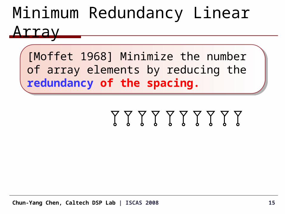
Minimum Redundancy Linear Array
15Chun-Yang Chen, Caltech DSP Lab | ISCAS 2008
[Moffet 1968] Minimize the number of array elements by reducing the redundancy of the spacing.
[Moffet 1968] Minimize the number of array elements by reducing the redundancy of the spacing.
Minimum Redundancy Linear Array
16Chun-Yang Chen, Caltech DSP Lab | ISCAS 2008
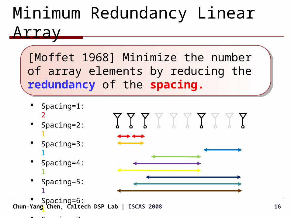
[Moffet 1968] Minimize the number of array elements by reducing the redundancy of the spacing.
[Moffet 1968] Minimize the number of array elements by reducing the redundancy of the spacing.
Spacing=1: 2 Spacing=2: 1 Spacing=3: 1 Spacing=4: 1 Spacing=5: 1 Spacing=6: 1 Spacing=7: 1 Spacing=8: 1 Spacing=9: 1

Minimum Redundancy Linear Array Given the desired aperture L, the minimum
redundancy array can be found by the following optimization problem:
17Chun-Yang Chen, Caltech DSP Lab | ISCAS 2008
2/321
subject to
min
'
L},,,{}x{x
N}||{x
N
kk
k
}{xk
2/L

18Chun-Yang Chen, Caltech DSP Lab | ISCAS 2008
3Minimum Redundancy MIMO Radar
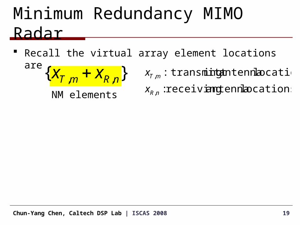
Minimum Redundancy MIMO Radar Recall the virtual array element locations are
19Chun-Yang Chen, Caltech DSP Lab | ISCAS 2008
locations antenna receiving :
locations antenna ing transmitt:
,
,
nR
mT
x
x
NM elements
}{ ,, nRmT xx

Minimum Redundancy MIMO Radar Recall the virtual array element locations are
The spacings between the virtual array elements are
20Chun-Yang Chen, Caltech DSP Lab | ISCAS 2008
}{ ,, nRmT xx locations antenna receiving :
locations antenna ing transmitt:
,
,
nR
mT
x
x
}{ ',',,, nRmTnRmT xxxx
NM elements
N2M2 spacings

Minimum Redundancy MIMO Radar The minimum redundancy MIMO Radar can be found by
solving the following optimization problem:
21Chun-Yang Chen, Caltech DSP Lab | ISCAS 2008
2/21
subject to
min
',',,,
,
,
, ,,
L},,{}xxx{x
M}||{x
N}||{x
MN
nRmTnRmT
nR
mT
}{x}{x nRmT
Example of the minimum redundancy MIMO Radar
22Chun-Yang Chen, Caltech DSP Lab | ISCAS 2008
0 10 20 30 40 50 60
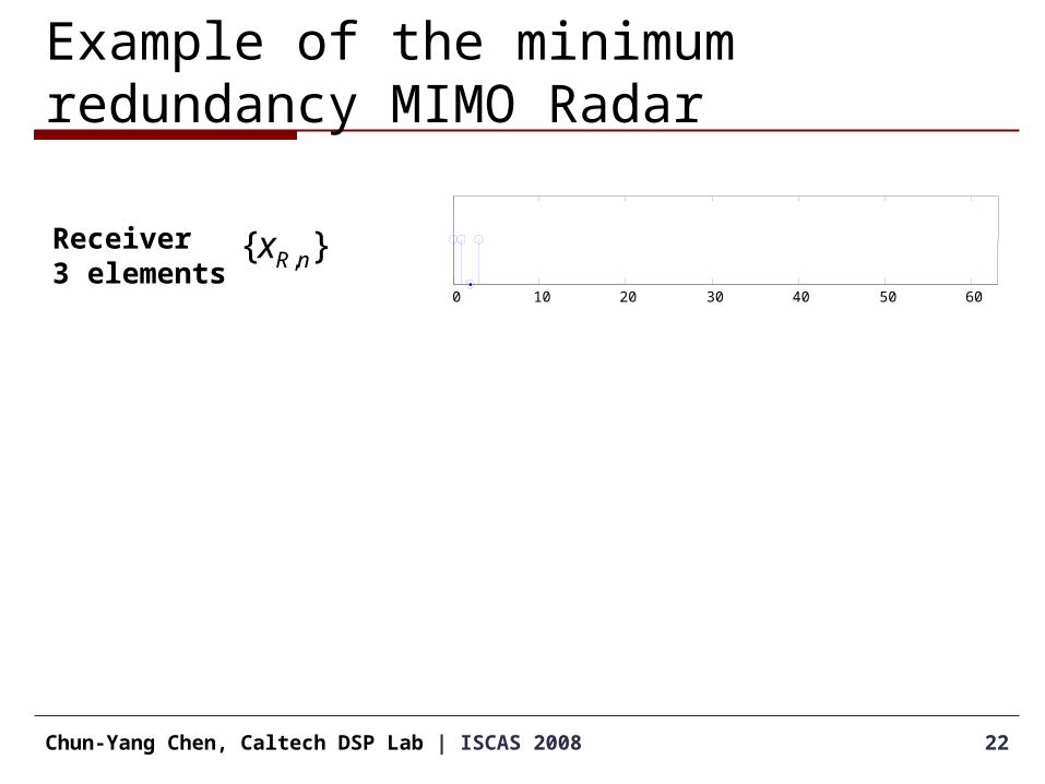
Receiver3 elements
}{ ,nRx

Example of the minimum redundancy MIMO Radar
23Chun-Yang Chen, Caltech DSP Lab | ISCAS 2008
0 10 20 30 40 50 60
0 10 20 30 40 50 60
Receiver3 elements
Transmitter5 elements
}{ ,mTx
}{ ,nRx
Example of the minimum redundancy MIMO Radar
24Chun-Yang Chen, Caltech DSP Lab | ISCAS 2008
0 10 20 30 40 50 60
0 10 20 30 40 50 60
0 10 20 30 40 50 60
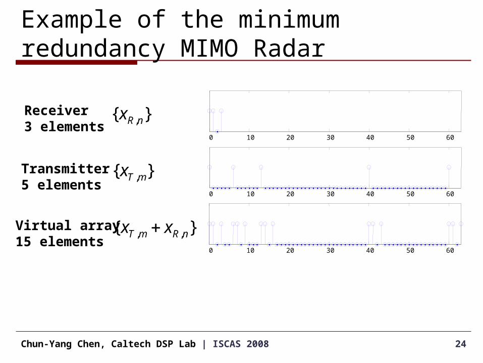
Receiver3 elements
Transmitter5 elements
Virtual array15 elements
}{ ,, nRmT xx
}{ ,mTx
}{ ,nRx

Example of the minimum redundancy MIMO Radar
25Chun-Yang Chen, Caltech DSP Lab | ISCAS 2008
0 10 20 30 40 50 60
0 10 20 30 40 50 60
0 10 20 30 40 50 60
Receiver3 elements
Transmitter5 elements
Virtual array15 elements
0 10 20 30 40 50 600
5
10
Histogram ofSpacings
}{ ,, nRmT xx
}{ ,mTx
}{ ,nRx
}
{
',',
,,
nRmT
nRmT
xx
xx
0 20 40 60
0 20 40 60
0 20 40 60
0 20 40 60
0 20 40 60
0 20 40 60
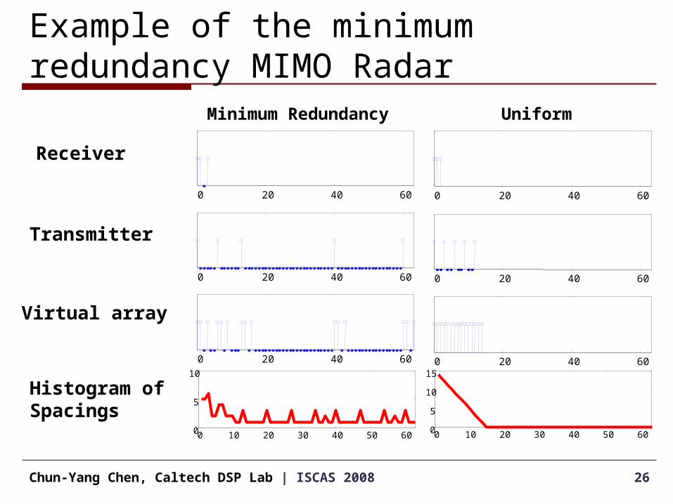
Example of the minimum redundancy MIMO Radar
26Chun-Yang Chen, Caltech DSP Lab | ISCAS 2008
Receiver
Transmitter
Virtual array
Histogram ofSpacings
Minimum Redundancy Uniform
0 10 20 30 40 50 600
5
10
0 10 20 30 40 50 600
5
10
15
Simulations: MVDR beamformer
27Chun-Yang Chen, Caltech DSP Lab | ISCAS 2008
-80 -60 -40 -20 0 20 40 60 80-60
-50
-40
-30
-20
-10
0
10
20
30
40
Angle (degree)
Beam
patt
ern
(d
B)
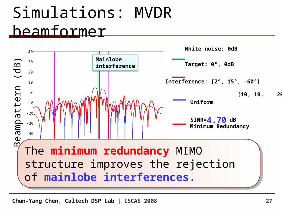
Target: 0°, 0dB
Interference: [2°, 15°, -60°]
[10, 10, 20] dB
Minimum
Redundancy
SINR=9.74 dB
Uniform
SINR=4.70 dB
Mainlobe interference
White noise: 0dB
The minimum redundancy MIMO structure improves the rejection of mainlobe interferences.
The minimum redundancy MIMO structure improves the rejection of mainlobe interferences.
Simulations: MVDR beamformer
28Chun-Yang Chen, Caltech DSP Lab | ISCAS 2008
-80 -60 -40 -20 0 20 40 60 80-60
-50
-40
-30
-20
-10
0
10
20
30
40
Angle (degree)
Beam
patt
ern
(d
B)
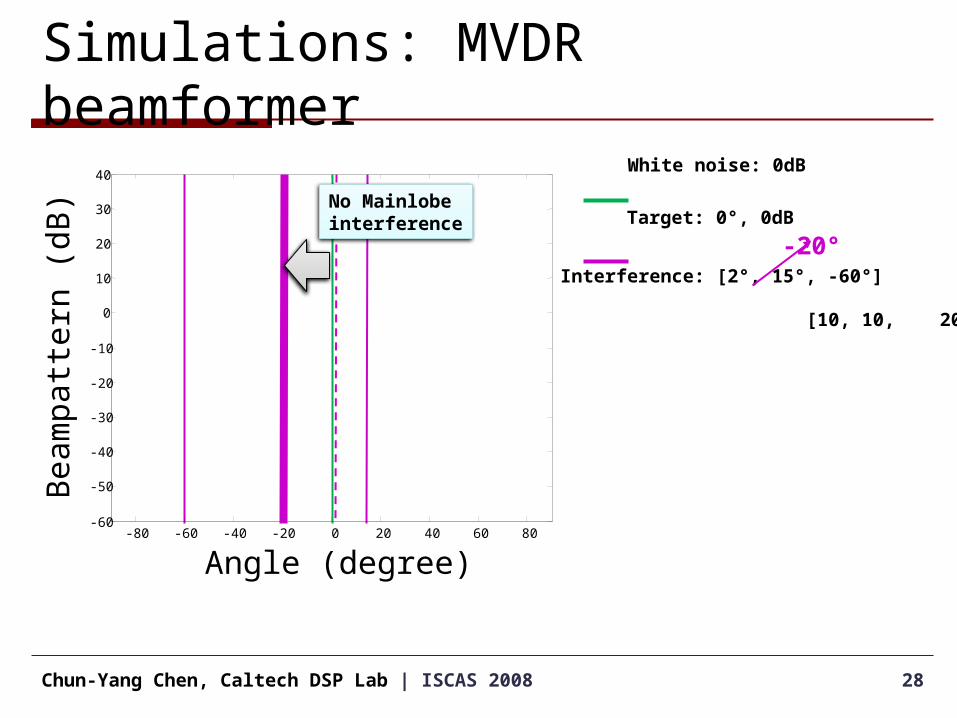
Target: 0°, 0dB
Interference: [2°, 15°, -60°]
[10, 10, 20] dB
-20°
White noise: 0dB
No Mainlobe interference

Simulations: MVDR beamformer
29Chun-Yang Chen, Caltech DSP Lab | ISCAS 2008
-80 -60 -40 -20 0 20 40 60 80-60
-50
-40
-30
-20
-10
0
10
20
30
40
Angle (degree)
Beam
patt
ern
(d
B)
Target: 0°, 0dB
Interference: [-20°, 15°, -60°]
[10, 10, 20] dB
Minimum
Redundancy
SINR=11.19 dB
Uniform
SINR=11.70 dB
White noise: 0dB
When there is no mainlobe interference, the minimum redundancy and uniform MIMO structure have about the same SINR.
When there is no mainlobe interference, the minimum redundancy and uniform MIMO structure have about the same SINR.
Conclusion & Future work
We have extended the minimum redundancy idea to the MIMO radar.– Reducing multiple occurrence of identical spacings in the
virtual array– Larger aperture can be obtained with fewer elements– The simulation shows that the proposed structure
improves rejection of mainlobe interference.
Future work– Design the nonuniform MIMO array structure with more
sophisticated optimization criteria.
30Chun-Yang Chen, Caltech DSP Lab | ISCAS 2008

Q&AThank You!
Any questions?
31Chun-Yang Chen, Caltech DSP Lab | ISCAS 2008
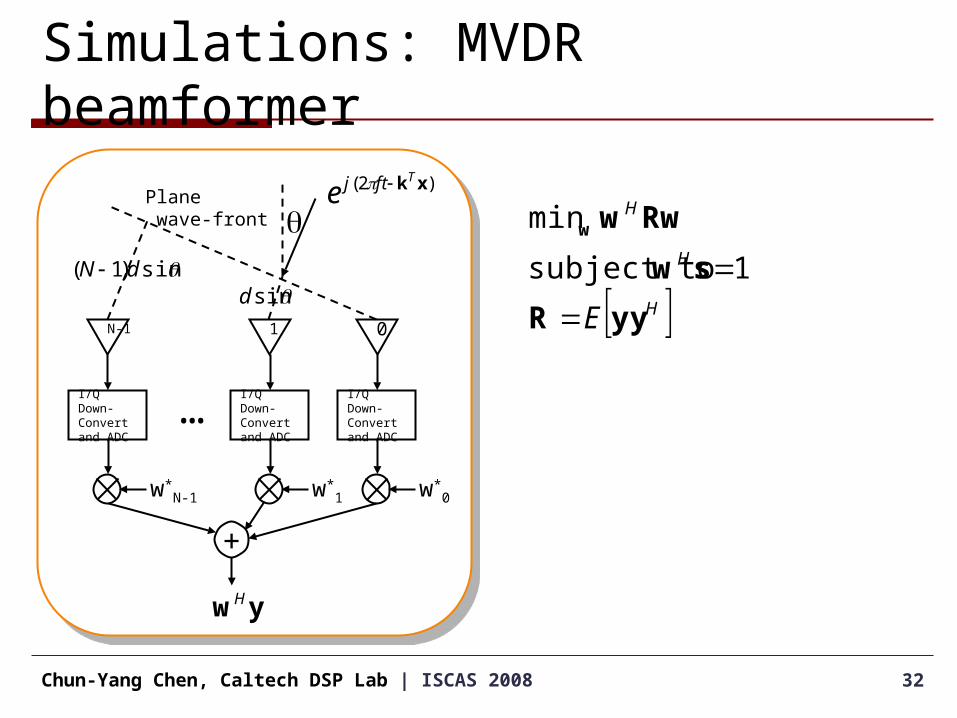
Simulations: MVDR beamformer
32Chun-Yang Chen, Caltech DSP Lab | ISCAS 2008
)2( xkTftje
N-1
I/Q Down-Convert and ADC
w*N-1
1
I/Q Down-Convert and ADC
w*1
0
I/Q Down-Convert and ADC
w*0
+
…
Plane wave-front q
sindsin)1( dN
ywH
HH
H
E yyR
sw
Rwww
1 subject to
min
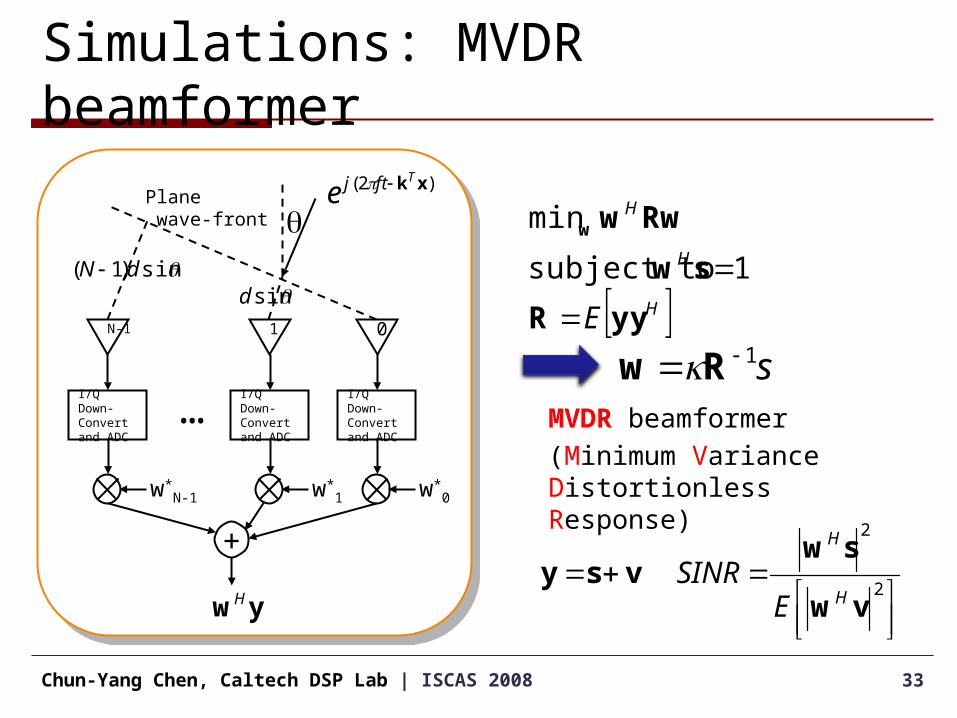
Simulations: MVDR beamformer
33Chun-Yang Chen, Caltech DSP Lab | ISCAS 2008
)2( xkTftje
N-1
I/Q Down-Convert and ADC
w*N-1
1
I/Q Down-Convert and ADC
w*1
0
I/Q Down-Convert and ADC
w*0
+
…
Plane wave-front q
sindsin)1( dN
ywH
HH
H
E yyR
sw
Rwww
1 subject to
min
s1 Rw MVDR beamformer
(Minimum Variance Distortionless Response)
2
2
vw
swvsy
H
H
ESINR