Embed Size (px)
Citation preview
2007 Air Carrier Compliance Group http://www.air-compliance.com Date: 09/15/2007 Revision: Original Page: i
MINIMUM EQUIPMENT LIST FOR PART 135 OPERATIONS
536 Beechcraft Avenue Chesterfield, Missouri 63005
(636) 532-1918
MINIMUM EQUIPMENT LIST
2007 Air Carrier Compliance Group http://www.air-compliance.com Date: 09/15/2007 Revision: Original Page: ii
TABLE OF CONTENTS
COVER -
Table of Contents ................................................................................................................................................................... ii Operator and Aircraft Information ......................................................................................................................................... vii List of Effective Pages ......................................................................................................................................................... viii Log/Record Of Revisions ........................................................................................................................................................x Definitions .............................................................................................................................................................................. xi Preamble ............................................................................................................................................................................. xiv Management Program .......................................................................................................................................................... xv STEP BY STEP-HOW TO USE THE MEL........................................................................................................................... xix Fleet Differences................................................................................................................................................................... xx System 21 Air Conditioning.....................................................................................................................................................1
20-1 Ventilation Blower System.......................................................................................................................1 20-2 Overhead Air Outlets ...............................................................................................................................1 20-3 Cabin Ceiling Outlet System ...................................................................................................................1 20-4 Defog Select Levers ................................................................................................................................1 20-5 Side Window Electric Defog Blower Systems .........................................................................................1 30-1 Automatic Pressurization Controller ........................................................................................................1 30-2 Manual Pressurization Controller ............................................................................................................2 30-3 Cabin Altitude and Differential Pressure Indicator ..................................................................................2 30-4 Cabin Rate of Climb Indicator .................................................................................................................2 30-5 Outflow Valves.........................................................................................................................................2 30-6 Cabin Dump Valve...................................................................................................................................3 30-7 Cabin Pressurization Warning System....................................................................................................3 50-1 Vapor Cycle Air Conditioning ..................................................................................................................4 60-1 Cockpit Temperature Control System .....................................................................................................5 60-2 Cabin Temperature Control System........................................................................................................5
System 22 Auto Flight.............................................................................................................................................................6 10-1 Autopilot System......................................................................................................................................6 10-2 Flight Director System .............................................................................................................................7 10-3 Yaw Damper............................................................................................................................................8
System 23 Communications ...................................................................................................................................................9 10-1 Communications Systems (VHF Comm. 1 and 2) ..................................................................................9 10-2 Ground Comm. Power System................................................................................................................9
MINIMUM EQUIPMENT LIST
2007 Air Carrier Compliance Group http://www.air-compliance.com Date: 09/15/2007 Revision: Original Page: iii
20-1 Emergency Locator Transmitter (ELT) ....................................................................................................9 40-1 Passenger Address System (PA)..........................................................................................................10 50-1 Flight Deck Speakers ............................................................................................................................11 50-2 Headsets ...............................................................................................................................................11 50-5 Hand Microphones ................................................................................................................................11 50-6 Push to Talk Switch ...............................................................................................................................11 50-7 Boom Microphones................................................................................................................................11 60-1 Static Discharge Wicks..........................................................................................................................12 60-2 Surface Bonding Straps.........................................................................................................................12 70-1 Cockpit Voice Recorder (CVR)..............................................................................................................12
System 24 Electrical Power ..................................................................................................................................................13 20-1 AC Inverters...........................................................................................................................................13 20-2 AC Inverter Fail Annunciators ...............................................................................................................13 20-4 AC Voltmeter .........................................................................................................................................13 30-1 DC Ammeters ........................................................................................................................................13 30-2 Standby Power System .........................................................................................................................13 30-3 DC Generator Failure Caution Annunciators.........................................................................................14 40-1 External Power System .........................................................................................................................14
System 25 Equipment / Furnishings .....................................................................................................................................15 00-1 Passenger Convenience Items / Non-Essential Equipment and Furnishings.......................................15 10-1 Cockpit Door..........................................................................................................................................15 10-2 Flashlight Stowage Assembly ...............................................................................................................16 10-3 Cockpit Sun Visors ................................................................................................................................16 10-4 External Mounted Airspeed Indicator Bugs...........................................................................................16 10-5 Crew Seats ............................................................................................................................................16 20-1 Passenger Seats ...................................................................................................................................17 20-2 Seat Belt/Shoulder Harness Side Facing Seats....................................................................................18 30-1 Galley Waste Receptacles Access Doors/Covers/Drawers ..................................................................18 40-1 Lavatory Door ........................................................................................................................................19 40-2 Lavatory Waste System.........................................................................................................................19 50-1 Cargo Restraint Systems.......................................................................................................................19 60-1 Emergency Medical Equipment.............................................................................................................20 60-2 Flotation Devices ...................................................................................................................................20
System 26 Fire Protection.....................................................................................................................................................21 10-1 Engine Fire Bell OFF Button Indicator (White Glare shield Button) ......................................................21 10-2 Tail Cone Baggage Compartment Smoke Detection Systems .............................................................21
MINIMUM EQUIPMENT LIST
2007 Air Carrier Compliance Group http://www.air-compliance.com Date: 09/15/2007 Revision: Original Page: iv
10-3 Cabin Smoke Detector ..........................................................................................................................21 20-1 Engine Fire Bottle Discharge Indicator..................................................................................................21 20-2 Portable Fire Extinguishers ...................................................................................................................21
System 27 Flight Controls.....................................................................................................................................................22 10-1 Roll Trim Indicator .................................................................................................................................22 40-1 Stabilizer Trim Indicator Dot ..................................................................................................................22 50-1 “LDG FLAP DELAY” Annunciator..........................................................................................................22 60-1 “SPD BRAKE EXTEND” Annunciator....................................................................................................22 70-1 Gust Control Lock..................................................................................................................................22
System 28 Fuel.....................................................................................................................................................................24 20-1 Fuselage Tank Fuel Transfer System ...................................................................................................24 20-2 Fuel Cross-feed System........................................................................................................................24 40-1 Wing Fuel Quantity Indicating Systems.................................................................................................25 40-2 Fuselage Tank Fuel Quantity Indicator .................................................................................................25 40-3 Fuel Totalizer.........................................................................................................................................26
System 29 Hydraulic Power..................................................................................................................................................27 30-1 Main System Pressure Gauge ..............................................................................................................27 30-2 Hydraulic Pump Pressure Low Annunciators ........................................................................................27 30-3 “HYD LEVEL LO” Annunciator ..............................................................................................................27
System 30 Ice and Rain Protection.......................................................................................................................................28 10-1 Wing Anti-Ice System ............................................................................................................................28 10-2 Horizontal Stabilizer Anti-Ice / Deice System........................................................................................28 20-1 Engine Anti-Ice Systems .......................................................................................................................28 30-1 Stall Warning Vane Heaters ..................................................................................................................29 30-2 Pitot Heaters..........................................................................................................................................30 30-3 Static Port Heat Systems.......................................................................................................................30 40-1 Windshield Heat Systems-High Position ...............................................................................................30 40-2 Windshield Wipers.................................................................................................................................31 80-1 Ice Detector System ..............................................................................................................................31
System 31 Indicating / Recording Systems...........................................................................................................................32 20-1 Clocks....................................................................................................................................................32 20-2 Flight Hour Meter...................................................................................................................................32 50-1 Unassigned Annunciators......................................................................................................................32 50-2 Master Caution Annunciator..................................................................................................................32 50-3 Master Warning Annunciator.................................................................................................................32
System 32 Landing Gear ......................................................................................................................................................33
MINIMUM EQUIPMENT LIST
2007 Air Carrier Compliance Group http://www.air-compliance.com Date: 09/15/2007 Revision: Original Page: v
30-1 Landing Gear Control ............................................................................................................................33 40-1 Wheel Brake Anti-Skid System .............................................................................................................33 60-1 Landing Gear Aural Warning Silence Buttons.......................................................................................33
System 33 Lights ..................................................................................................................................................................34 10-1 Cockpit and Instrument Lighting System...............................................................................................34 20-1 Passenger Notice System .....................................................................................................................34 20-2 Cabin Interior Lighting System ..............................................................................................................34 30-1 Baggage Compartment Light System ...................................................................................................35 40-1 Position Lights System ..........................................................................................................................35 40-2 Anti-Collision Light System (Strobe)......................................................................................................35 40-3 Rotating Beacon (Flashing)...................................................................................................................35 40-4 Landing Lights .......................................................................................................................................35 40-5 Wing Inspection Lights ..........................................................................................................................35 40-6 Recognition Light System......................................................................................................................35 40-7 Tail Logo Lights .....................................................................................................................................36 50-2 Cabin Emergency Lighting Test Light ...................................................................................................36
System 34 Navigation ...........................................................................................................................................................37 10-1 Vertical Speed Indicators (VSI) .............................................................................................................37 10-2 V-Speeds Select Button (Air Data Select Panel) ..................................................................................37 10-3 Barometric Push-Standard Button.........................................................................................................37 10-5 Altitude Alerting System ........................................................................................................................37 10-6 Angle of Attack (AOA) Indexer (Glare shield)........................................................................................37 20-1 Standby AHRS Power Supply ...............................................................................................................37 20-2 Non-Stabilized Magnetic Compass .......................................................................................................38 20-3 Turn Indication Systems........................................................................................................................38 20-4 Slip/Skid Indicators ................................................................................................................................38 20-5 Display Controls ....................................................................................................................................38 20-6 Course Heading Panel ..........................................................................................................................39 20-7 Multi-Function Display (MFD) / Navigation Display (ND) ......................................................................39 20-8 Sensor Display Unit (SDU)....................................................................................................................39 30-1 Marker Beacon System .........................................................................................................................40 40-1 Thunderstorm Detection Equipment......................................................................................................40 40-2 Weather Radar System .........................................................................................................................40 40-3 Radio Altimeter System.........................................................................................................................40 40-4 Terrain Awareness and Warning System (TAWS)................................................................................40 40-7 Traffic Alert Collision Avoidance System (TCAS) II ..............................................................................42
MINIMUM EQUIPMENT LIST
2007 Air Carrier Compliance Group http://www.air-compliance.com Date: 09/15/2007 Revision: Original Page: vi
50-1 Distance Measuring Equipment (DME) .................................................................................................44 50-2 ATC Transponders and Automatic Altitude Reporting Systems ...........................................................44 50-4 Navigation Systems (ADF, VOR/ILS, GPS, LORAN, Doppler, RNAV, INS).........................................44 50-5 Navigation System Database ................................................................................................................45 60-1 Control Display Unit (CDU)....................................................................................................................45 60-2 Flight Management System (FMS)........................................................................................................45 60-3 Data Base Unit ......................................................................................................................................46
System 35 Oxygen................................................................................................................................................................47 00-1 Oxygen Discharge Indicator Disk ..........................................................................................................47 20-1 Passenger Oxygen................................................................................................................................47
System 46 Information Systems ...........................................................................................................................................50 00-1 Line Advance Button .............................................................................................................................50
System 52 Doors ..................................................................................................................................................................51 10-1 Cabin Entry Door ...................................................................................................................................51 20-1 Emergency Exit Seal System ................................................................................................................52 30-1 Baggage Door Snubber.........................................................................................................................52 30-2 Baggage Door Key Lock........................................................................................................................52 70-1 Door Annunciator System......................................................................................................................52
System 73 Engine Fuel & Control .........................................................................................................................................54 20-1 Fuel Flow Indicators ..............................................................................................................................54
System 74 Ignition ................................................................................................................................................................55 10-1 Igniter Indicator Lights. ..........................................................................................................................55
System 76 Engine Controls ..................................................................................................................................................56 01-1 Engine Synchronizer System ................................................................................................................56
System 77 Engine Indicating ................................................................................................................................................57 10-1 N1 Indicator ...........................................................................................................................................57 10-2 N2 Indicator ...........................................................................................................................................57 30-1 Engine Vibrations Meters ......................................................................................................................57
System 78 Engine Exhaust...................................................................................................................................................58 30-1 Thrust Reverser Systems......................................................................................................................58
System 79 Engine Oil ...........................................................................................................................................................59 30-1 Oil Pressure Low Annunciators .............................................................................................................59 30-2 Remote Oil Level Sensing System........................................................................................................59

MINIMUM EQUIPMENT LIST
2007 Air Carrier Compliance Group http://www.air-compliance.com Date: 09/15/2007 Revision: Original Page: vii
OPERATOR AND AIRCRAFT INFORMATION
APPROVED FOR USE UNDER CFR 14 CFR Part 135
OPERATOR LEGAL NAME Corporate Aircraft Management, Inc.
OPERATOR MAILING ADDRESS 536 Beechcraft Avenue Chesterfield, Missouri 63005 (636) 532-1918
MAIN CONTACT Paul Scholl, Director of Operations
MAIN CONTACT TELEPHONE NUMBER 636-532-1918
PHYSICAL ADDRESS OF MAIN OPERATIONS 536 Beechcraft Avenue Chesterfield, Missouri 63005 (636) 532-1918
MAIN OPERATIONS BASE AIRPORT Sprit of St. Louis, (KSUS)
BASED ON MMEL DATE / REVISION 06/08/2007 / Rev. 7
AIRCRAFT INFORMATION N148J N482DM N800GF N106CG
MAKE Mitsubishi Mitsubishi Beech Beech
MODEL MU-300 MU-300 BE-400A BE-400
SERIAL NUMBER A033 S.A. A088 S.A. RK-96 RJ-12
MFR YEAR 1983 1984 1994 1986
MINIMUM EQUIPMENT LIST
2007 Air Carrier Compliance Group http://www.air-compliance.com Date: 09/15/2007 Revision: Original Page: viii
LIST OF EFFECTIVE PAGES
NOTE: Individual pages are not replaced during revisions or changes. The entire section (Preamble, 21 Air Cond) is removed and replaced; therefore each page is not separated into individual rows.
CHAPTER, SECTION OR SYSTEM PAGE REVISION REVISION DATE FAA DATE
COVER PAGE i Original 09/15/2007 06/08/2007
TABLE OF CONTENTS ii - vi Original 09/15/2007 06/08/2007
OPERATOR INFORMATION vii Original 09/15/2007 NA
LIST OF EFFECTIVE PAGES viii - ix Original 09/15/2007 06/08/2007
LOG/RECORD OF REVISIONS x Original 09/15/2007 06/08/2007
DEFINITIONS xi - xii Original 09/15/2007 06/08/2007
PREAMBLE xiv Original 09/15/2007 NA
MANAGEMENT PROGRAM xv - xviii Original 09/15/2007 NA
STEP BY STEP-HOW TO USE THE MEL xix Original 09/15/2007 NA
FLEET DIFFERENCES xx - xxi Original 09/15/2007 NA
21 AIR CONDITIONING Original 09/15/2007 06/08/2007
22 AUTO FLIGHT Original 09/15/2007 06/08/2007
23 COMMUNICATIONS Original 09/15/2007 06/08/2007
24 ELECTRICAL POWER Original 09/15/2007 06/08/2007
25 EQUIPMENT/FURNISHINGS Original 09/15/2007 06/08/2007
27 FIRE PROTECTION Original 09/15/2007 06/08/2007
27 FLIGHT COMTROLS Original 09/15/2007 06/08/2007
28 FUEL Original 09/15/2007 06/08/2007
29 HYDRAULIC POWER Original 09/15/2007 06/08/2007
MINIMUM EQUIPMENT LIST
2007 Air Carrier Compliance Group http://www.air-compliance.com Date: 09/15/2007 Revision: Original Page: ix
CHAPTER, SECTION OR SYSTEM PAGE REVISION REVISION DATE FAA DATE
30 ICE AND RAIN PROTECTION Original 09/15/2007 06/08/2007
31 INDICATING/RECORDING SYSTEMS Original 09/15/2007 06/08/2007
32 LANDING GEAR Original 09/15/2007 06/08/2007
33 LIGHTS Original 09/15/2007 06/08/2007
34 NAVIGATION Original 09/15/2007 06/08/2007
35 OXYGEN Original 09/15/2007 06/08/2007
52 DOORS Original 09/15/2007 06/08/2007
73 ENGINE FUEL & OIL Original 09/15/2007 06/08/2007
74 IGNITION Original 09/15/2007 06/08/2007
77 ENGINE INDICATING Original 09/15/2007 06/08/2007
78 ENGINE EXHAUST Original 09/15/2007 06/08/2007
79 ENGINE OIL Original 09/15/2007 06/08/2007
FILE: CAMI_MEL_Fleet_Rev39
FAA Approval Stamp and/or Sign-off:
An FAA approval stamp and/or sign-off in this area approves this manual and requires its use
MINIMUM EQUIPMENT LIST
2007 Air Carrier Compliance Group http://www.air-compliance.com Date: 09/15/2007 Revision: Original Page: x
LOG/RECORD OF REVISIONS
REVISION CHAPTER, SECTION OR SYSTEM REVISED
NEW PAGES, CHAPTER, SECTION OR SYSTEM NEW DATE
Original Original issue All 9/15/2007
1
2
3
4
5
6
7
8
9
10
11
12
13
14
MINIMUM EQUIPMENT LIST
2007 Air Carrier Compliance Group http://www.air-compliance.com Date: 09/15/2007 Revision: Original Page: xi
DEFINITIONS
1. System Definitions. System numbers are based on the Air Transport Association (ATA) Specification Number 100 and items re numbered sequentially.
a. "Item" (Column 1) means the equipment, system, component, or function listed in the "Item" column.
b. "Number Installed" (Column 2) is the number (quantity) of items normally installed in the aircraft. This number represents the aircraft configuration considered in developing this MMEL. Should the number be a variable (e.g., passenger cabin items) a number is not required.
c. "Number Required for Dispatch" (Column 3) is the minimum number (quantity) of items required for operation provided the conditions specified in Column 4 are met.
NOTE: Where the MMEL shows a variable number required for dispatch, the MEL must reflect the actual number required for dispatch or an alternate means of configuration control approved by the Administrator.
d. "Remarks or Exceptions" (Column 4) in this column includes a statement either prohibiting or permitting operation with a specific number of items inoperative, provisos (conditions and limitations) for such operation, and appropriate notes.
e. A vertical bar (change bar) in the margin indicates a change, addition or deletion in the adjacent text for the current revision of that page only. The change bar is dropped at the next revision of that page.
2. "Airplane/Rotorcraft Flight Manual" (AFM/RFM) is the document required for type certification and approved by the responsible FAA Aircraft Certification Office. The FAA approved AFM/RFM for the specific aircraft is listed on the applicable Type Certificate Data Sheet.
3. "As required by FAR" means that the listed item is subject to certain provisions (restrictive or permissive) expressed in the Federal Aviation Regulations operating rules. The number of items required by the FAR must be operative. When the listed item is not required by FAR it may be inoperative for time specified by repair category.
4. Each inoperative item must be placarded to inform and remind the crewmembers and maintenance personnel of the equipment condition.
NOTE: To the extent practical, placards should be located adjacent to the control or indicator for the item affected; however, unless otherwise specified, placard wording and location will be determined by the operator.
5. "-" symbol in Column 2 and/or Column 3 indicates a variable number (quantity) of the item installed.
6. "Deleted" in the remarks column after a sequence item indicates that the item was previously listed but is now required to be operative if installed in the aircraft.
7. "ER" refers to extended range operations of a two-engine airplane which has a type design approval for ER operations and complies with the provisions of Advisory Circular 120-42A.
8. "Federal Aviation Regulations" (FAR) means the applicable portions of the Federal Aviation Act and Federal Aviation Regulations.
9. "Flight Day" means a 24 hour period (from midnight to midnight) either Universal Coordinated Time (UCT) or local time, as established by the operator, during which at least one flight is initiated for the affected aircraft.
10. "Icing Conditions" means an atmospheric environment that may cause ice to form on the aircraft or in the engine(s).
11. Alphabetical symbol in Column 4 indicates a proviso (condition or limitation) that must be complied with for operation with the listed item inoperative.
12. "Inoperative" means a system and/or component malfunction to the extent that it does not accomplish its intended purpose and/or is not consistently functioning normally within its approved operating limit(s) or tolerance(s).
MINIMUM EQUIPMENT LIST
2007 Air Carrier Compliance Group http://www.air-compliance.com Date: 09/15/2007 Revision: Original Page: xii
13. "Notes:" in Column 4 provides additional information for crewmember or maintenance consideration. Notes are used to identify applicable material which is intended to assist with compliance, but do not relieve the operator of the responsibility for compliance with all applicable requirements. Notes are not a part of the provisos.
14. Inoperative components of an inoperative system: Inoperative items which are components of a system which is inoperative are usually considered components directly associated with and having no other function than to support that system. (Warning/caution systems associated with the inoperative system must be operative unless relief is specifically authorized per the MMEL).
15. "(M)" symbol indicates a requirement for a specific maintenance procedure which must be accomplished prior to operation with the listed item inoperative. Normally these procedures are accomplished by maintenance personnel; however, other personnel may be qualified and authorized to perform certain functions. Procedures requiring specialized knowledge or skill, or requiring the use of tools or test equipment should be accomplished by maintenance personnel. The satisfactory accomplishment of all maintenance procedures, regardless of who performs them, is the responsibility of the operator. Appropriate procedures are required to be published as part of the operator's manual or MEL.
16. "(O)" symbol indicates a requirement for a specific operations procedure which must be accomplished in planning for and/or operating with the listed item inoperative. Normally these procedures are accomplished by the flight crew; however, other personnel may be qualified and authorized to perform certain functions. The satisfactory accomplishment of all procedures, regardless of who performs them, is the responsibility of the operator. Appropriate procedures are required to be published as a part of the operator's manual or MEL.
NOTE: The (M) and (O) symbols are required in the operator's MEL unless otherwise authorized by the Administrator.
17. "Deactivated" and "Secured" means that the specified component must be put into an acceptable condition for safe flight. An acceptable method of securing or deactivating will be established by the operator.
18. "Visual Flight Rules" (VFR) is as defined in FAR Part 91. This precludes a pilot from filing an Instrument Flight Rules (IFR) flight plan.
19. "Visual Meteorological Conditions" (VMC) means the atmospheric environment is such that would allow a flight to proceed under the visual flight rules applicable to the flight. This does not preclude operating under Instrument Flight Rules.
20. "Visible Moisture" means an atmospheric environment containing water in any form that can be seen in natural or artificial light; for example, clouds, fog, rain, sleet, hail, or snow.
21. "Passenger Convenience Items" means those items related to passenger convenience, comfort or entertainment such as, but not limited to, galley equipment, movie equipment, ash trays, stereo equipment, overhead reading lamps, etc.
22. Repair Intervals: All users of an MEL approved under FAR 121, 125, 129 and 135 must effect repairs of inoperative systems or components, deferred in accordance with the MEL, at or prior to the repair times established by the following letter designators:
Category A. Items in this category shall be repaired within the time interval specified in the remarks column of the operator's approved MEL.
Category B. Items in this category shall be repaired within three (3) consecutive calendar days (72 hours), excluding the day the malfunction was recorded in the aircraft maintenance record/logbook. For example, if it were recorded at 10 a.m. on January 26th, the three day interval would begin at midnight the 26th and end at midnight the 29th.
Category C. Items in this category shall be repaired within ten (10) consecutive calendar days (240 hours), excluding the day the malfunction was recorded in the aircraft maintenance record/logbook. For example, if it were recorded at 10 a.m. on January 26th, the 10 day interval would begin at midnight the 26th and end at midnight February 5th.
Category D. Items in this category shall be repaired within one hundred and twenty (120) consecutive calendar days (2880 hours), excluding the day the malfunction was recorded in the aircraft maintenance log and/or record.
The letter designators are inserted adjacent to Column 2.
23. Electronic fault alerting system - General New generation aircraft display system fault indications to the flight crew by use of computerized display systems. Each aircraft manufacturer has incorporated individual design philosophies in determining the data that would be represented. The following are customized definitions (specific to each manufacturer) to help determine the level of messages affecting
MINIMUM EQUIPMENT LIST
2007 Air Carrier Compliance Group http://www.air-compliance.com Date: 09/15/2007 Revision: Original Page: xiii
the aircraft's dispatch status. When preparing the MEL document, operators are to select the proper Definition No. 23 for their aircraft, if appropriate.
24. "Administrative control item" means an item listed by the operator in the MEL for tracking and informational purposes. It may be added to an operator's MEL by approval of the Principal Operations Inspector provided no relief is granted, or provided conditions and limitations are contained in an approved document (i.e. Structural Repair Manual, airworthiness directive, etc.). If relief other than that granted by an approved document is sought for an administrative control item, a request must be submitted to the Administrator. If the request results in review and approval by the FOEB, the item becomes an MMEL item rather than an administrative control item.
25. "" symbol in Column 1 indicates an item which is not required by regulation but which may have been installed on some models of aircraft covered by this MMEL. This item may be included on the operator's MEL after the approving office has determined that the item has been installed on one or more of the operator's aircraft. The symbol, however, shall not be carried forward into the operator's MEL. It should be noted that neither this policy nor the use of this symbol provide authority to install or remove an item from an aircraft.
26. "Excess Items" means those items that have been installed that are redundant to the requirements of the FARs.
27. "Day of Discovery" is the calendar day an equipment/instrument malfunction was recorded in the aircraft maintenance log and or record. This day is excluded from the calendar days or flight days specified in the MMEL for the repair of an inoperative item of equipment. This provision is applicable to all MMEL items, i.e., categories "A, B, C, and D."
MINIMUM EQUIPMENT LIST
2007 Air Carrier Compliance Group http://www.air-compliance.com Date: 09/15/2007 Revision: Original Page: xiv
PREAMBLE
The following is applicable for authorized certificate holders operating under Federal Aviation Regulations (FAR) Parts 121, 125, 129, 135: The FAR require that all equipment installed on an aircraft in compliance with the Airworthiness Standards and the Operating Rules must be operative. However, the Rules also permit the publication of a Minimum Equipment List (MEL) where compliance with certain equipment requirements is not necessary in the interests of safety under all operating conditions. Experience has shown that with the various levels of redundancy designed into aircraft, operation of every system or installed component may not be necessary when the remaining operative equipment can provide an acceptable level of safety. A Master Minimum Equipment List (MMEL) is developed by the FAA, with participation by the aviation industry, to improve aircraft utilization and thereby provide more convenient and economic air transportation for the public. The FAA approved MMEL includes those items of equipment related to airworthiness and operating regulations and other items of equipment which the Administrator finds may be inoperative and yet maintain an acceptable level of safety by appropriate conditions and limitations; it does not contain obviously required items such as wings, flaps, and rudders. The MMEL is the basis for development of individual operator MELs which take into consideration the operator's particular aircraft equipment configuration and operational conditions. Operator MELs, for administrative control, may include items not contained in the MMEL; however, relief for administrative control items must be approved by the Administrator. An operator's MEL may differ in format from the MMEL, but cannot be less restrictive than the MMEL. The individual operator's MEL, when approved and authorized, permits operation of the aircraft with inoperative equipment.
Equipment not required by the operation being conducted and equipment in excess of FAR requirements are included in the MEL with appropriate conditions and limitations. The MEL must not deviate from the Aircraft Flight Manual Limitations, Emergency Procedures or with Airworthiness Directives. It is important to remember that all equipment related to the airworthiness and the operating regulations of the aircraft not listed on the MMEL must be operative.
Suitable conditions and limitations in the form of placards, maintenance procedures, crew operating procedures and other restrictions as necessary are specified in the MEL to ensure that an acceptable level of safety is maintained.
The MEL is intended to permit operation with inoperative items of equipment for a period of time until repairs can be accomplished. It is important that repairs be accomplished at the earliest opportunity. In order to maintain an acceptable level of safety and reliability the MMEL establishes limitations on the duration of and conditions for operation with inoperative equipment. The MEL provides for release of the aircraft for flight with inoperative equipment. When an item of equipment is discovered to be inoperative, it is reported by making an entry in the Aircraft Maintenance Record/Logbook as prescribed by FAR. The item is then either repaired or may be deferred per the MEL or other approved means acceptable to the Administrator prior to further operation. MEL conditions and limitations, do not relieve the operator from determining that the aircraft is in condition for safe operation with items of equipment inoperative.
When these requirements are met, an Airworthiness Release, Aircraft Maintenance Record/Logbook entry, or other approved documentation is issued as prescribed by FAR. Such documentation is required prior to operation with any item of equipment inoperative.
Operators are responsible for exercising the necessary operational control to ensure that an acceptable level of safety is maintained. When operating with multiple inoperative items, the interrelationships between those items and the effect on aircraft operation and crew workload will be considered.
Operators are to establish a controlled and sound repair program including the parts, personnel, facilities, procedures, and schedules to ensure timely repair.
WHEN USING THE MEL, COMPLIANCE WITH THE STATED INTENT OF THE PREAMBLE, DEFINITIONS, AND THE CONDITIONS AND LIMITATIONS SPECIFIED IN THE MEL IS REQUIRED.
MINIMUM EQUIPMENT LIST
2007 Air Carrier Compliance Group http://www.air-compliance.com Date: 09/15/2007 Revision: Original Page: xv
MANAGEMENT PROGRAM
LIMITATIONS 1. The MEL shall not conflict with AFM limitations, CFR’s, emergency procedures, or airworthiness directives. Suitable
limitations in the form of placards, maintenance procedures, pilot operating procedures, and other restrictions as necessary are specified in the MEL to ensure that an acceptable level of safety is maintained.
2. Compliance with this MEL, which is mandatory, will result in the highest level of safety. If the Pilot in Command is ever in doubt of operating the aircraft with an item inoperative, even if approved to do so under the MEL, that pilot shall not operate the aircraft.
3. ITEMS NOT LISTED ON THE MEL MUST BE OPERATIVE.
4. The MEL lists all items of installed equipment that may be inoperative. The MEL does not contain obviously required items such as wingsds, flaps, rudders, etc. Inoperative items may include instruments and equipment required by the airworthiness standards under which the aircraft is type certificated, instruments and equipment required by the operating rules, and items in excess of these requirements.
5. The MEL is not a list of items required to be in the aircraft.
6. The MEL does not provide the authority to install or remove an item from the aircraft.
7. Extensions to the maximum repair interval for category A and D items is not authorized.
8. A defect entered into the aircraft’s maintenance record/logbook in effect removes the aircraft from service. The aircraft remains out of service until the defect is corrected or deferred and an appropriate maintenance person returns the aircraft to service. Maintenance personnel can reflect this approval for return to service in the aircraft’s maintenance record/logbook in one of two ways:
An entry showing the corrective action that was taken for the defect; appropriate maintenance personnel sign the entry and include the signer’s certificate number, or
A deferral statement with the signature of a person authorized to defer needed maintenance for the operator.
INOPERATIVE COMPONENTS WITHIN A SYSTEM MEL provisions for inoperative items which are components of a system usually consider that the system overall is operative. When the system is inoperative, however, there usually is no need for the component to be operative. Therefore, any component directly associated with and having no function other than supporting a system listed in the MEL may be inoperative when that system is inoperative. However, warning/caution systems associated with the inoperative system must be operative unless relief is specifically authorized in the MEL.
OPERATOR RESPONSIBILITIES The FAA grants deferral per the MEL only after maintenance personnel have determined that the aircraft is safe to be flown and that the specific conditions, limitations, and procedures for that item have been accomplished. The satisfactory accomplishment of all procedures is primarily the responsibility of Fedair, LLC. This responsibility may be delegated to qualified persons when published in the Fedair, LLC’s manual or this MEL.
In addition to the specified MEL conditions and limitations, Fedair, LLC’s is responsible for determining that the aircraft is in condition for safe operation. When necessary, detailed procedures for release of the aircraft with inoperative items have been included in the MEL. Additionally some items require the pilot to contact an authorized mechanic to determine airworthiness.
DIRECTOR OF MAINTENANCE RESPONSIBILITIES 1. Oversight and compliance with this MEL.
2. Oversight of this Management Program for compliance.
3. Repairs are made within the times allowed for deferral.
MINIMUM EQUIPMENT LIST
2007 Air Carrier Compliance Group http://www.air-compliance.com Date: 09/15/2007 Revision: Original Page: xvi
4. Tracking the inoperative items on each aircraft
5. Maintaining the records required for an airworthiness release, aircraft maintenance record or logbook entry, or other approved documentation as described in the section: STEP BY STEP-HOW TO USE THE MEL
PILOT RESPONSIBILITIES 1. Entering the discrepancies noted into the Aircraft Discrepancy Log, and when required by the MEL, contact the Director of
Maintenance and communicate the item(s) as the earliest time possible.
2. Following the release for return to service, the appropriate conditions and limitations as prescribed by the MEL must be applied for continued operations.
3. When preparing to operate with multiple inoperative items, the interrelationship between those items and the effect on aircraft operation and pilot workload must be considered by the Fedair, LLC’ pilot.
4. The Aircraft Discrepancy Log and Deferred Maintenance Items forms shall be dispatched with the aircraft on all flights. It shall be the duty of each PIC to review these forms prior to each flight as part of his preflight duties.
DEFERRAL PROCEDURE Upon discovery of a discrepancy:
1. Enter a description of the discrepancy and the ATA System and Item number in the "Discrepancy" column. Be as descriptive and accurate as possible. Note any additional information that may assist maintenance trouble shoot the item if it is not obvious.
2. If the item(s) can not be deferred as per MEL, the aircraft is grounded until repaired. Contact the Director of Maintenance. If the item(s) can be deferred, continue with this procedure.
3. If a written aircraft discrepancy is reviewed and found to be eligible for deferral, accomplish the procedures in the STEP BY STEP HOW TO USE THE MEL section.
4. Before dispatch ensure that the Corrective Action column lists the corrective action performed and is signed off.
5. Generally the Director of Maintenance or qualified mechanic should accomplish corrective action procedures, and make the corresponding entry. The PIC may make the deferring entry if there are no (M) procedures.
6. (M) Procedures shall be entered on the form and are one-time items, such as securing a circuit breaker. (O) Procedures need to be checked before each flight for an operational limitation.
7. The "Mechanic & Cert #" column shall have the signature of the PIC or Mechanic who deferred and/or corrected the item along with their license #.
8. When these conditions are satisfied, the aircraft may be considered airworthy and returned to service.
Placarding shall he accomplished as follows:
1. When the MEL references an (O) procedure, the PIC is authorized to perform it, and shall affix the placard.
2. When the MEL references an (M) procedure, qualified maintenance personnel are required, and maintenance personnel shall affix the placard.
3. If an (M) procedure and an (O) procedure are listed, pilot placarding is authorized after he has received a maintenance technicians sign off on the Aircraft Discrepancy Log.
Unless otherwise stated in the COMMENTS column of this MEL, placement of the placard labels shall be accomplished in the following manner:
1. On the face of the instrument (gauge).
2. On the face of the indicator (warning light).
3. Directly above or adjacent to the switch controlling the system.
4. On the inoperative item. Example: On the microphone.
MINIMUM EQUIPMENT LIST
2007 Air Carrier Compliance Group http://www.air-compliance.com Date: 09/15/2007 Revision: Original Page: xvii
5. For placarding items that do not have a panel or switch (such as an inoperative passenger seat), place the placard next to the aircraft “N” number placard on the instrument panel.
6. Placards must be installed in full view of the pilot.
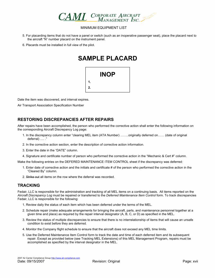
SAMPLE PLACARD
Date the item was discovered, and interval expires.
Air Transport Association Specification Number
RESTORING DISCREPANCIES AFTER REPAIRS After repairs have been accomplished, the person who performed the corrective action shall enter the following information on the corresponding Aircraft Discrepancy Log page:
1. In the discrepancy column enter “clearing MEL item (ATA Number) ……..originally deferred on…… (date of original deferral) …. .”
2. In the corrective action section, enter the description of corrective action information.
3. Enter the date in the “DATE” column.
4. Signature and certificate number of person who performed the corrective action in the “Mechanic & Cert #” column.
Make the following entries on the DEFERED MAINTENANCE ITEM CONTROL sheet if the discrepancy was deferred:
1. Enter date of corrective action and the initials and certificate # of the person who performed the corrective action in the “Cleared By” column.
2. Strike out all items on the row where the deferral was recorded.
TRACKING Fedair, LLC is responsible for the administration and tracking of all MEL items on a continuing basis. All items reported on the Aircraft Discrepancy Log must be repaired or transferred to the Deferred Maintenance Item Control form. To track discrepancies Fedair, LLC is responsible for the following:
1. Review daily the status of each item which has been deferred under the terms of the MEL.
2. Schedule repair (make adequate arrangements for bringing the aircraft, parts, and maintenance personnel together at a given time and place) as required by the repair interval designator (A, B, C, or D) as specified in the MEL.
3. Review the status of multiple discrepancies to ensure that there is no interrelationship of items that will cause an unsafe condition to exist before they are deferred.
4. Monitor the Company flight schedule to ensure that the aircraft does not exceed any MEL time limits.
5. Use the Deferred Maintenance Item Control form to track the date and time of each deferred item and its subsequent repair. Except as provided below (see Tracking MEL Extensions) of this MEL Management Program, repairs must be accomplished as specified by the interval designator in the MEL.
INOP 1.
2.
MINIMUM EQUIPMENT LIST
2007 Air Carrier Compliance Group http://www.air-compliance.com Date: 09/15/2007 Revision: Original Page: xviii
MEL EXTENSIONS Our operations specifications provide a procedure for the extension of MEL deferral times that do not allow us to complete the necessary repairs within the allotted time period. Any extension must be reported to the FAA in writing as indicated below under REPORTING MEL EXTENSIONS to the FSDO. Fedair, LLC shall ensure that all MEL deferrals, whether short-term or subject to extended deferral, are tracked according to the date of the original deferral, and recorded in the Aircraft Discrepancy Log as follows:
1. Only time intervals for Category B and C items may be extended.
2. An entry is made in the Aircraft Discrepancy Log referring to the MEL item, date, MEL and authorization number.
3. Entry made in the Corrective Action column of the AML: “THE TIME LIMIT IS EXTENDED PER (Enter the reason; part back order date, or delivery date as appropriate) AND LIST NEW EXPIRATION DATE.”
4. The new expiration date will be indicated at the space located above the DATE of the Aircraft Placard.
5. The original expiration date will be void by drawing an X through it.
REPORTING MEL EXTENSIONS The following procedures are to be observed following an MEL time extension:
Fedair, LLC shall send a written message to the CHDO within 24 hours listing those items which have exceeded the limitations of Category B and C. The message must include:
1. Date of message
2. Aircraft registration number and type
3. MEL reference, including item number, title and category of MEL
4. Date placarded
5. Reason for extension
6. Estimated repair date
7. The message shall be forwarded to the CHDO. This copy will serve as the Company's Document of Notification of Extension.
8. The copy will be retained for 30 days after the item is restored and then discarded.
DISCREPANCIES DURING FLIGHT OR AWAY FROM HOME BASE 1. Maintenance performed on a Company aircraft while away from the Principle Operations Base shall be limited to only
correct /repair discrepancies that have been entered on the Aircraft Discrepancy Log.
2. The PlC shall insure that qualified FAA certified personnel or an authorized FAA Certified Repair Station accomplishes all maintenance performed on Company aircraft while away from the Principle Operations Base.
3. Obtain a copy of the approved drug and alcohol program per FAR 135.251 and 135.255.
4. All maintenance shall be performed within the parameters stipulated herein as well as applicable FAR’s, the Manufacturer’s Maintenance Manuals and the factory-approved inspection program.
5. All maintenance shall be inspected and signed off by qualified personnel or an appropriate maintenance release documented in the Aircraft Discrepancy Log.
6. The PlC shall obtain a detailed work order or invoice containing an accurate and complete description of the work accomplished, and a list of component parts utilized and the component airworthiness tags when applicable.
7. The repair work order shall accompany the aircraft to the Principal Operations Base and then kept with the aircraft records.
8. Before a discrepancy is deferred the appropriate M and/or O procedures shall be accomplished and placards installed if necessary.
MINIMUM EQUIPMENT LIST
2007 Air Carrier Compliance Group http://www.air-compliance.com Date: 09/15/2007 Revision: Original Page: xix
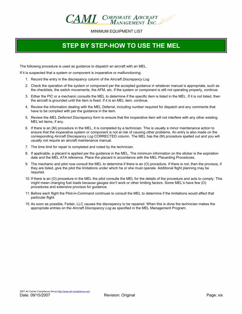
STEP BY STEP-HOW TO USE THE MEL
The following procedure is used as guidance to dispatch an aircraft with an MEL.
If it is suspected that a system or component is inoperative or malfunctioning:
1. Record the entry in the discrepancy column of the Aircraft Discrepancy Log.
2. Check the operation of the system or component per the accepted guidance in whatever manual is appropriate, such as the checklists, the switch movements, the AFM, etc. If the system or component is still not operating properly, continue.
3. Either the PIC or a mechanic consults the MEL to determine if the specific item is listed in the MEL. If it is not listed, then the aircraft is grounded until the item is fixed. If it is an MEL item, continue.
4. Review the information dealing with the MEL Deferral, including number required for dispatch and any comments that have to be complied with per the guidance in the item.
5. Review the MEL Deferred Discrepancy form to ensure that the inoperative item will not interfere with any other existing MEL’ed items, if any.
6. If there is an (M) procedure in the MEL, it is completed by a technician. This is usually a minor maintenance action to ensure that the inoperative system or component is not at risk of causing other problems. An entry is also made on the corresponding Aircraft Discrepancy Log CORRECTED column. The MEL has the (M) procedure spelled out and you will usually not require an aircraft maintenance manual.
7. The time limit for repair is completed and noted by the technician.
8. If applicable, a placard is applied per the guidance in the MEL. The minimum information on the sticker is the expiration date and the MEL ATA reference. Place the placard in accordance with the MEL Placarding Procedures.
9. The mechanic and pilot now consult the MEL to determine if there is an (O) procedure. If there is not, then the provisos, if they are listed, give the pilot the limitations under which he or she must operate. Additional flight planning may be required.
10. If there is an (O) procedure in the MEL the pilot consults the MEL for the details of the procedure and acts to comply. This might mean changing fuel loads because gauges don’t work or other limiting factors. Some MEL’s have few (O) procedures and extensive provisos for guidance.
11. Before each flight the Pilot-in-Command continues to consult the MEL to determine if the limitations would affect that particular flight.
15. As soon as possible, Fedair, LLC causes the discrepancy to be repaired. When this is done the technician makes the appropriate entries on the Aircraft Discrepancy Log as specified in the MEL Management Program.
MINIMUM EQUIPMENT LIST
2007 Air Carrier Compliance Group http://www.air-compliance.com Date: 09/15/2007 Revision: Original Page: xx
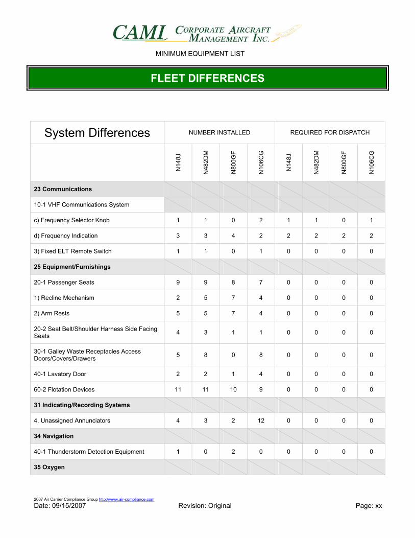
FLEET DIFFERENCES
System Differences NUMBER INSTALLED REQUIRED FOR DISPATCH
N14
8J
N48
2DM
N80
0GF
N10
6CG
N14
8J
N48
2DM
N80
0GF
N10
6CG
23 Communications
10-1 VHF Communications System
c) Frequency Selector Knob 1 1 0 2 1 1 0 1
d) Frequency Indication 3 3 4 2 2 2 2 2
3) Fixed ELT Remote Switch 1 1 0 1 0 0 0 0
25 Equipment/Furnishings
20-1 Passenger Seats 9 9 8 7 0 0 0 0
1) Recline Mechanism 2 5 7 4 0 0 0 0
2) Arm Rests 5 5 7 4 0 0 0 0
20-2 Seat Belt/Shoulder Harness Side Facing Seats 4 3 1 1 0 0 0 0
30-1 Galley Waste Receptacles Access Doors/Covers/Drawers 5 8 0 8 0 0 0 0
40-1 Lavatory Door 2 2 1 4 0 0 0 0
60-2 Flotation Devices 11 11 10 9 0 0 0 0
31 Indicating/Recording Systems
4. Unassigned Annunciators 4 3 2 12 0 0 0 0
34 Navigation
40-1 Thunderstorm Detection Equipment 1 0 2 0 0 0 0 0
35 Oxygen
MINIMUM EQUIPMENT LIST
2007 Air Carrier Compliance Group http://www.air-compliance.com Date: 09/15/2007 Revision: Original Page: xxi
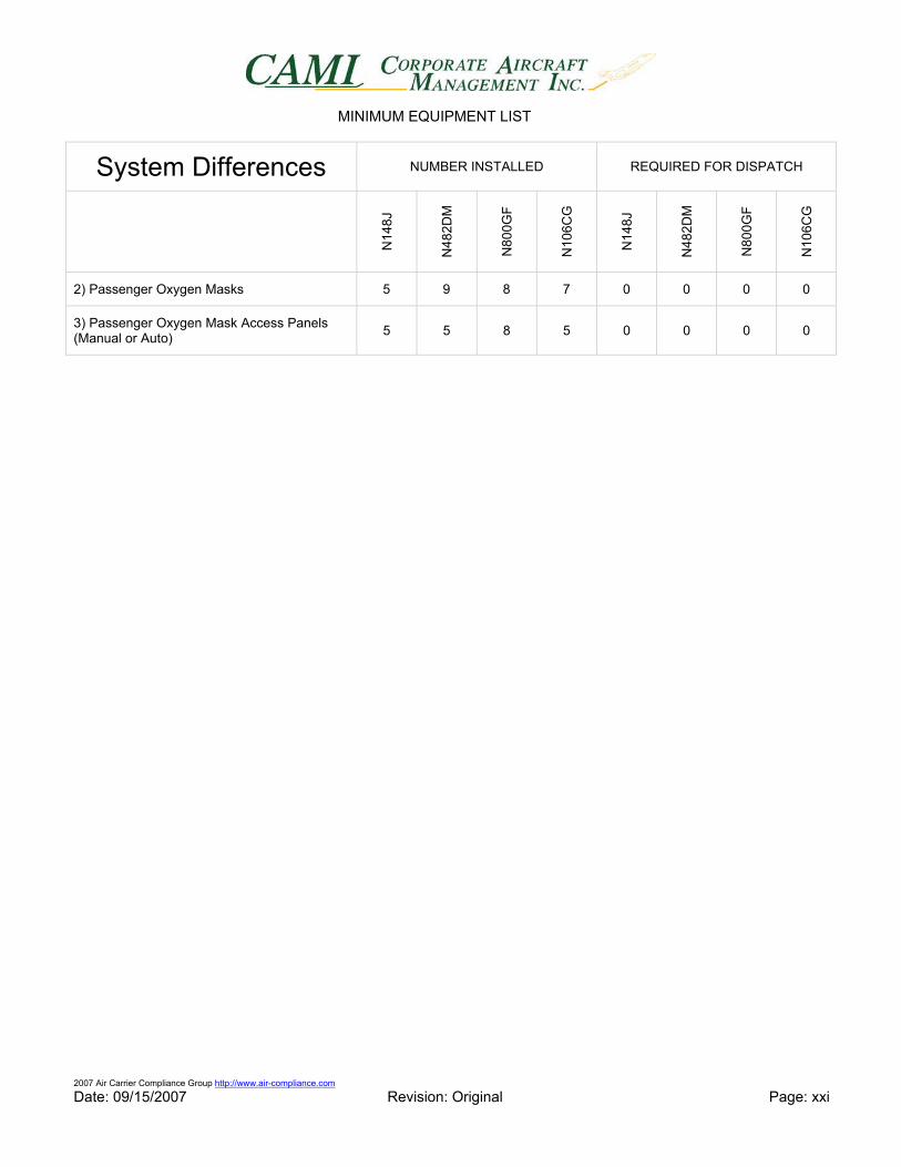
System Differences NUMBER INSTALLED REQUIRED FOR DISPATCH
N14
8J
N48
2DM
N80
0GF
N10
6CG
N14
8J
N48
2DM
N80
0GF
N10
6CG
2) Passenger Oxygen Masks 5 9 8 7 0 0 0 0
3) Passenger Oxygen Mask Access Panels (Manual or Auto) 5 5 8 5 0 0 0 0
MINIMUM EQUIPMENT LIST
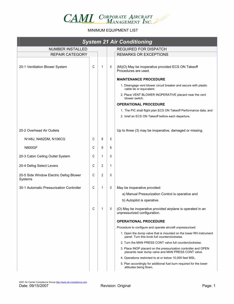
2007 Air Carrier Compliance Group http://www.air-compliance.com Date: 09/15/2007 Revision: Original Page: 1
System 21 Air Conditioning NUMBER INSTALLED REQUIRED FOR DISPATCH REPAIR CATEGORY REMARKS OR EXCEPTIONS
20-1 Ventilation Blower System C 1 0 (M)(O) May be inoperative provided ECS ON Takeoff Procedures are used.
MAINTENANCE PROCEDURE
1. Disengage vent blower circuit breaker and secure with plastic cable tie or equivalent.
2. Place VENT BLOWER INOPERATIVE placard near the vent blower switch.
OPERATIONAL PROCEDURE 1. The PIC shall flight plan ECS ON Takeoff Performance data, and
2. brief an ECS ON Takeoff before each departure.
20-2 Overhead Air Outlets Up to three (3) may be inoperative, damaged or missing.
N148J, N482DM, N106CG C 8 5
N800GF C 9 6
20-3 Cabin Ceiling Outlet System C 1 0
20-4 Defog Select Levers C 2 1
20-5 Side Window Electric Defog Blower Systems
C 2 0
30-1 Automatic Pressurization Controller C 1 0 May be inoperative provided:
a) Manual Pressurization Control is operative and
b) Autopilot is operative.
C 1 0 (O) May be inoperative provided airplane is operated in an unpressurized configuration.
OPERATIONAL PROCEDURE Procedure to configure and operate aircraft unpressurized.
1. Open the dump valve that is mounted on the lower RH instrument panel. Turn this knob full counterclockwise.
2. Turn the MAN PRESS CONT valve full counterclockwise.
3. Place INOP placard on the pressurization controller and OPEN placards near dump valve and MAN PRESS CONT valve.
4. Operations restricted to at or below 10,000 feet MSL.
5. Plan accordingly for additional fuel burn required for the lower altitudes being flown.
MINIMUM EQUIPMENT LIST
2007 Air Carrier Compliance Group http://www.air-compliance.com Date: 09/15/2007 Revision: Original Page: 2
System 21 Air Conditioning NUMBER INSTALLED REQUIRED FOR DISPATCH REPAIR CATEGORY REMARKS OR EXCEPTIONS
30-2 Manual Pressurization Controller C 1 0 (O) May be inoperative provided the airplane is operated in an unpressurized configuration.
OPERATIONAL PROCEDURE Procedure to configure and operate aircraft unpressurized.
1. Open the dump valve that is mounted on the lower RH instrument panel. Turn this knob full counterclockwise.
2. Set the pressurization controller to an aircraft altitude of 0.
3. Place INOP placard on the pressurization controller and OPEN placards near dump valve and MAN PRESS CONT valve.
4. Insure that the aircraft is operated at or below 10,000 feet MSL
5. Adjust fuel burn accordingly with the lower altitudes being flown.
30-3 Cabin Altitude and Differential Pressure Indicator
C 1 0 (O) May be inoperative provided airplane is operated in an unpressurized configuration.
1) Differential Pressure Indicator C 1 0 May be inoperative provided:
a) Cabin Rate of Climb Indicator is operative,
b) Cabin Altitude Indicator is operative and
c) Chart is available for crew to convert Cabin altitude to differential pressure.
OPERATIONAL PROCEDURE Procedure to configure and operate aircraft unpressurized
1. Open the dump valve that is mounted on the lower RH instrument panel. Turn this knob full counterclockwise.
2. Turn the MAN PRESS CONT valve full counterclockwise.
3. Place an INOP sticker on t he pressurization controller.
4. Insure that the aircraft is operated at or below 10,000 feet MSL.
5. Adjust fuel burn accordingly with the lower altitudes being flown.
30-4 Cabin Rate of Climb Indicator C 1 0 May be inoperative provided Cabin Altitude and Differential Pressure Indicators are operative.
30-5 Outflow Valves C 2 0 (M)(O) May be inoperative OPEN provided the airplane is operated in an unpressurized configuration.
MAINTENANCE PROCEDURE Procedures to ensure Outflow Valves are in OPEN position.
1. Open the dump valve that is mounted on the lower RH instrument panel. Turn this knob full counterclockwise.
2. Turn the MAN PRESS CONT valve full counterclockwise.
3. Place INOP placard on the pressurization controller and OPEN
MINIMUM EQUIPMENT LIST
2007 Air Carrier Compliance Group http://www.air-compliance.com Date: 09/15/2007 Revision: Original Page: 3
System 21 Air Conditioning NUMBER INSTALLED REQUIRED FOR DISPATCH REPAIR CATEGORY REMARKS OR EXCEPTIONS
placards near dump valve and MAN PRESS CONT valve.
4. Using a Tie-wrap, attach a material that will not damage the outflow valve seat, under the valve seat to physically hold the valve open.
5. Place a suitable placard near the pressurization control components on the instrument panel signifying that an outflow valve (or valves) is/are blocked open.
6. Flight Crew will determine that adequate oxygen and fuel is available for the planned flight.
OPERATIONAL PROCEDURE Procedure to configure and operate aircraft unpressurized.
1. Insure that the aircraft is operated at or below 10,000 feet MSL.
2. Adjust fuel burn accordingly with the lower altitudes being flown.
30-6 Cabin Dump Valve C 1 0 (M)(O) May be inoperative provided:
a) Dump Valve is secured in the OPEN position and
b) Aircraft is operated in an unpressurized configuration.
MAINTENANCE PROCEDURE 1. Open the dump valve that is mounted on the lower RH instrument
panel.
2. Turn this knob full counterclockwise and secure with safety wire.
OPERATIONAL PROCEDURE Procedure to configure and operate aircraft unpressurized.
1. Turn the MAN PRESS CONT valve full counterclockwise.
2. Place INOP placard on the pressurization controller and OPEN placards near dump valve and MAN PRESS CONT valve.
3. Insure that the aircraft is operated at or below 10,000 feet MSL.
4. Adjust fuel burn accordingly with the lower altitudes being flown.
30-7 Cabin Pressurization Warning System
1) “CABIN PRESS LO” Annunciator System
C 1 0 May be inoperative provided:
a) Cabin Altitude and Differential Pressure Indicators are operative and
b) Aircraft is operated at or below 10,000 feet MSL.
2) “CABIN PRESS HI” Annunciator System
C 1 0 (O) May be inoperative provided the airplane is operated in an unpressurized configuration.
Maintenance Procedure in 30-6 (configuring for unpressurized flight) must be completed by a qualified mechanic and the mechanic or flight crew must complete the Operations procedure.
MINIMUM EQUIPMENT LIST
2007 Air Carrier Compliance Group http://www.air-compliance.com Date: 09/15/2007 Revision: Original Page: 4
System 21 Air Conditioning NUMBER INSTALLED REQUIRED FOR DISPATCH REPAIR CATEGORY REMARKS OR EXCEPTIONS
MAINTENANCE PROCEDURE 1. Open the dump valve that is mounted on the lower RH instrument
panel.
2. Turn this knob full counterclockwise and secure with safety wire.
OPERATIONAL PROCEDURE Procedure to configure and operate aircraft unpressurized.
1. Turn the MAN PRESS CONT valve full counterclockwise.
2. Place INOP placard on the pressurization controller and OPEN placards near dump valve and MAN PRESS CONT valve.
3. Insure that the aircraft is operated at or below 10,000 feet MSL.
4. Adjust fuel burn accordingly with the lower altitudes being flown.
50-1 Vapor Cycle Air Conditioning C 1 0 (M)
MAINTENACE PROCEDURE Procedure to deactivate and secure the system.
1. Pull the AIR COND circuit breaker and collar with plastic cable tie or equivalent.
2. Place “Air Conditioner Inop.” placard near environmental controls.
1) Hour Meter C 1 0 (O)
OPERATIONAL PROCEDURE Procedure to record Vapor Cycle Air Conditioning System hours via alternate method.
1. Flight Crew will record START, and STOP times in the notes section on the same page as the discrepancy write up.
2. Compute flight time.
3. Keep log of flight time.
4. Once repaired the log information shall be transferred to the aircraft’s permanent records by a qualified mechanic.
2) AIR COND ON Indicator Light C 1 0 (O) May be inoperative provided alternate procedures are established and used to ensure compliance with AFM Limitations.
OPERATIONAL PROCEDURE Procedure to identify and ensure compliance with AFM procedures and Limitations.
MINIMUM EQUIPMENT LIST
2007 Air Carrier Compliance Group http://www.air-compliance.com Date: 09/15/2007 Revision: Original Page: 5
System 21 Air Conditioning NUMBER INSTALLED REQUIRED FOR DISPATCH REPAIR CATEGORY REMARKS OR EXCEPTIONS
60-1 Cockpit Temperature Control System
1) Automatic Temperature Control System
C 1 0 May be inoperative provided Manual Temperature Control System is operative.
2) Manual Temperature Control System C 1 0 May be inoperative provided Automatic Temperature Control System is operative.
60-2 Cabin Temperature Control System
1) Automatic Temperature Control System
C 1 0 May be inoperative provided Manual Temperature Control System is operative.
2) Manual Temperature Control System C 1 0 May be inoperative provided Automatic Temperature Control System is operative.
3) Cabin Temperature Indicator System C 1 0
4) PUSH TO TRANS Switch Indicator Light
C 1 0 May be inoperative provided Cabin Temperature Control is operated in the Manual Mode only.
MINIMUM EQUIPMENT LIST
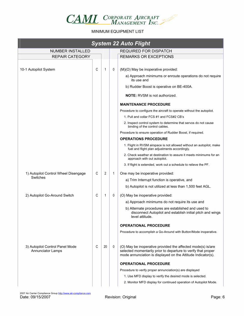
2007 Air Carrier Compliance Group http://www.air-compliance.com Date: 09/15/2007 Revision: Original Page: 6
System 22 Auto Flight NUMBER INSTALLED REQUIRED FOR DISPATCH REPAIR CATEGORY REMARKS OR EXCEPTIONS
10-1 Autopilot System C 1 0 (M)(O) May be inoperative provided:
a) Approach minimums or enroute operations do not require its use and
b) Rudder Boost is operative on BE-400A.
NOTE: RVSM is not authorized.
MAINTENANCE PROCEDURE Procedure to configure the aircraft to operate without the autopilot.
1. Pull and collar FCS #1 and FCS#2 CB’s
2. Inspect control system to determine that servos do not cause binding of the control cables.
Procedure to ensure operation of Rudder Boost, if required.
OPERATIONS PROCEDURE 1. Flight in RVSM airspace is not allowed without an autopilot, make
fuel and flight plan adjustments accordingly.
2. Check weather at destination to assure it meets minimums for an approach with out autopilot.
3. If flight is extended, work out a schedule to relieve the PF.
1) Autopilot Control Wheel Disengage Switches
C 2 1 One may be inoperative provided:
a) Trim Interrupt function is operative, and
b) Autopilot is not utilized at less than 1,500 feet AGL.
2) Autopilot Go-Around Switch C 1 0 (O) May be inoperative provided:
a) Approach minimums do not require its use and
b) Alternate procedures are established and used to disconnect Autopilot and establish initial pitch and wings level attitude.
OPERATIONAL PROCEDURE Procedure to accomplish a Go-Around with Button/Mode inoperative.
3) Autopilot Control Panel Mode Annunciator Lamps
C 20 0 (O) May be inoperative provided the affected mode(s) is/are selected momentarily prior to departure to verify that proper mode annunciation is displayed on the Attitude Indicator(s).
OPERATIONAL PROCEDURE Procedure to verify proper annunciation(s) are displayed
1. Use MFD display to verify the desired mode is selected.
2. Monitor MFD display for continued operation of Autopilot Mode.
MINIMUM EQUIPMENT LIST
2007 Air Carrier Compliance Group http://www.air-compliance.com Date: 09/15/2007 Revision: Original Page: 7
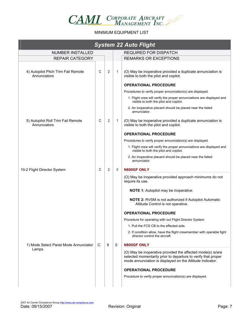
System 22 Auto Flight NUMBER INSTALLED REQUIRED FOR DISPATCH REPAIR CATEGORY REMARKS OR EXCEPTIONS
4) Autopilot Pitch Trim Fail Remote Annunciators
C 2 1 (O) May be inoperative provided a duplicate annunciation is visible to both the pilot and copilot.
OPERATIONAL PROCEDURE Procedures to verify proper annunciation(s) are displayed.
1. Flight crew will verify the proper annunciations are displayed and visible to both the pilot and copilot.
2. An inoperative placard should be placed near the failed annunciator.
5) Autopilot Roll Trim Fail Remote Annunciators
C 2 1 (O) May be inoperative provided a duplicate annunciation is visible to both the pilot and copilot.
OPERATIONAL PROCEDURE Procedures to verify proper annunciation(s) are displayed.
1. Flight crew will verify the proper annunciations are displayed and visible to both the pilot and copilot.
2. An inoperative placard should be placed near the failed annunciator.
10-2 Flight Director System C 2 0 N800GF ONLY
(O) May be inoperative provided approach minimums do not require its use.
NOTE 1: Autopilot may be inoperative.
NOTE 2: RVSM is not authorized if Autopilot Automatic Altitude Control is not operative.
OPERATIONAL PROCEDURE Procedure for operating with out Flight Director System
1. Pull the FCS CB to the effected side.
2. If condition allow, have the flight crewmember with operable fight director control the aircraft.
1) Mode Select Panel Mode Annunciator Lamps
C 9 0 N800GF ONLY
(O) May be inoperative provided the affected mode(s) is/are selected momentarily prior to departure to verify that proper mode annunciation is displayed on the Attitude Indicator.
OPERATIONAL PROCEDURE Procedure to verify proper annunciation(s) are displayed.