Embed Size (px)
Citation preview
Miniature Motors,Transmission and Control
Product Catalogue
Start
Move
Speed 24.00 rpmClockwise
NO spd feedback
Wait1,000 secs
Move
Speed 11.30 rpmClockwise
NO spd feedback
Wait1,000 secs
Rotalink
ww
w.ro
talin
k.c
om
Miniature Motors,Transmission and ControlMiniature Motors,Transmission and Control
Product Catalogue
Miniature Motors,Transmission and Control
Contact:[email protected]: +44 (0)1460 72000
Rotalink LimitedCropmead, CrewkerneSomerset TA18 7HQ, UK
www.rotalink.com
FM 24735
www.rotalink.comInfinite possibilities
Welcome to the Rotalinkcatalogue. Its purpose is topresent the widest range ofproducts in a way that makes it easy for you to satisfy yourrequirement. In the followingpages there are sections thatdeal with the selection processfor each of the following broadcatalogue headings:
• DC motors with optional gearboxes
• Control of DC Motors
• AC motors with optional gearboxes
• Stepping motors with optional gearboxes
• Customised design and build
Each section includes a briefguide to its use and is followedby detailed information.Component data sheets can be accessed from the enclosed CD or from www.rotalink.com.It may be possible for you tospecify your product by referringto the appropriate pages, if notdon’t be concerned. The realstrength of this catalogue lies inthe support that stands behind it.
The sales group at Rotalink areavailable to give both technicaland commercial support. Yourarea sales engineer will bepleased to offer telephone helpor visit you. The sales group aresupported by a design team ofspecialist engineers who maybe needed to deal with complexapplication issues.
The team is here to help youselect the optimum product foryour application.
Once your product is selectedthere may be a need for samples or prototypes. Our highly skilled and well equipped manufacturing support group is here to help. In conjunction with your sales engineer they will provide the product that will allow you to complete your evaluation with the confidence that you are meeting your technical and commercialobjectives.
Contents
Modularity 1Customisation 2
Introduction 3DC Motor Schedule - Permanent Magnet Brushed 5DC Motor Schedule - Brushless Heavy Case 7DC Motor Schedule - Brushless Pressed Case 8DC Motor Schedule - Rare Earth 9Linear Motion 10Gearbox Information 11 Introduction 25Incremental Encoder 27Absolute Encoders 29Electromagnetic Interference 30DC Programmable Controller 31Speed Controller 33Servo Systems 34
Introduction 35AC Motor Schedule - Unidirectional 37AC Motor Schedule - Reversible 38Gearbox Information 39
Introduction 47Stepping Motor Schedule - Bipolar Hybrid 49Stepping Motor Schedule - Bipolar PM 51Gearbox Information 53
Pneumatic and Electrical 61
Introduction 63
DC Motors andOptional Gearboxes
Introduction
Control of DC Motors
AC Motors andOptional Gearboxes
Permanent Magnetand Hybrid SteppingMotors
Cam Timers
Services to OEMs
Ovoid Spur/Planetary
Gearbox
Planetary Gearbox
Incremental Encoder
Absolute Encoder
Compound Encoder
Drives Chip Option
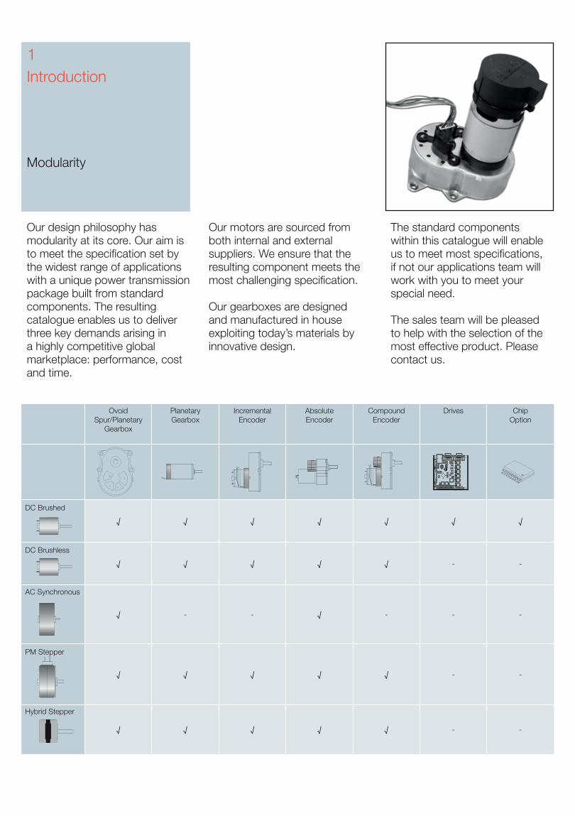
DC Brushed
√ √ √ √ √ √ √
DC Brushless
√ √ √ √ √ - -
AC Synchronous
√ - - √ - - -
PM Stepper
√ √ √ √ √ - -
Hybrid Stepper
√ √ √ √ √ - -
Introduction
Modularity
1
Our design philosophy has modularity at its core. Our aim is to meet the specification set by the widest range of applications with a unique power transmission package built from standard components. The resulting catalogue enables us to deliver three key demands arising in a highly competitive global marketplace: performance, cost and time.
Our motors are sourced from both internal and external suppliers. We ensure that the resulting component meets the most challenging specification.
Our gearboxes are designed and manufactured in house exploiting today’s materials by innovative design.
The standard components within this catalogue will enable us to meet most specifications, if not our applications team will work with you to meet your special need.
The sales team will be pleased to help with the selection of the most effective product. Please contact us.
12
3
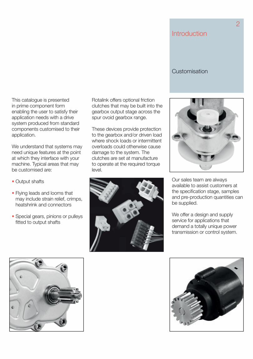
This catalogue is presented in prime component form enabling the user to satisfy their application needs with a drive system produced from standard components customised to their application.
We understand that systems may need unique features at the point at which they interface with your machine. Typical areas that may be customised are:
• Output shafts
• Flying leads and looms that may include strain relief, crimps, heatshrink and connectors
• Special gears, pinions or pulleys fitted to output shafts
Introduction Customisation
2
Our sales team are always available to assist customers at the specification stage, samples and pre-production quantities can be supplied.
We offer a design and supply service for applications that demand a totally unique power transmission or control system.
Rotalink offers optional friction clutches that may be built into the gearbox output stage across the spur ovoid gearbox range.
These devices provide protection to the gearbox and/or driven load where shock loads or intermittent overloads could otherwise cause damage to the system. The clutches are set at manufacture to operate at the required torque level.
3
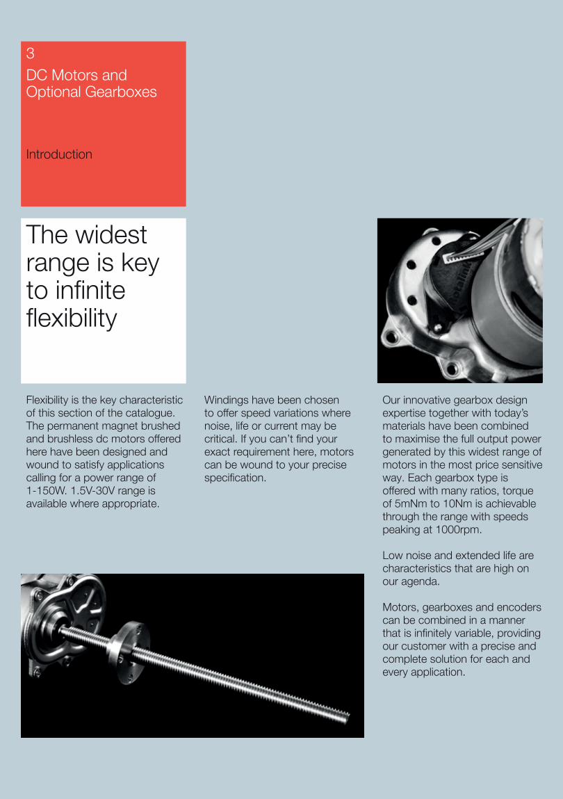
The widest range is key to infinite flexibility
Flexibility is the key characteristic of this section of the catalogue. The permanent magnet brushed and brushless dc motors offered here have been designed and wound to satisfy applications calling for a power range of 1-150W. 1.5V-30V range is available where appropriate.
Windings have been chosen to offer speed variations where noise, life or current may be critical. If you can’t find your exact requirement here, motors can be wound to your precise specification.
Our innovative gearbox design expertise together with today’s materials have been combined to maximise the full output power generated by this widest range of motors in the most price sensitive way. Each gearbox type is offered with many ratios, torque of 5mNm to 10Nm is achievable through the range with speeds peaking at 1000rpm.
Low noise and extended life are characteristics that are high on our agenda.
Motors, gearboxes and encoders can be combined in a manner that is infinitely variable, providing our customer with a precise and complete solution for each and every application.
DC Motors and Optional Gearboxes
Introduction
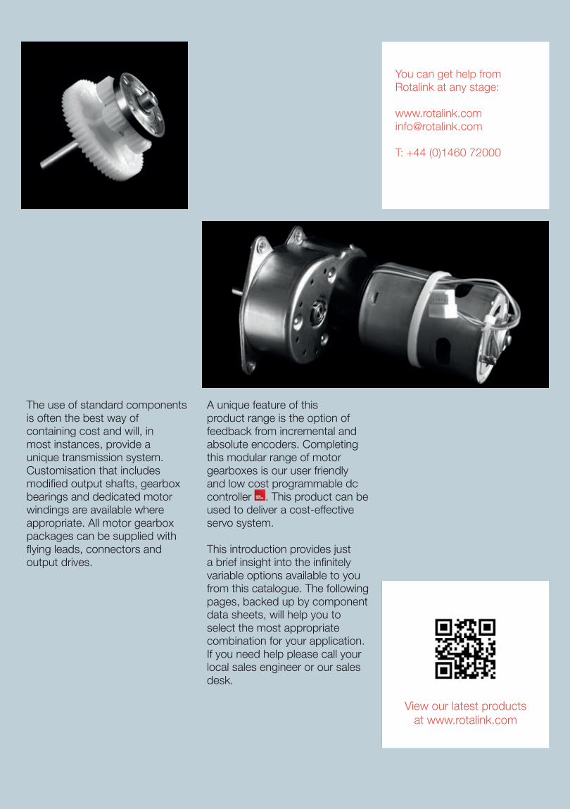
The use of standard components is often the best way of containing cost and will, in most instances, provide a unique transmission system. Customisation that includes modified output shafts, gearbox bearings and dedicated motor windings are available where appropriate. All motor gearbox packages can be supplied with flying leads, connectors and output drives.
A unique feature of this product range is the option of feedback from incremental and absolute encoders. Completing this modular range of motor gearboxes is our user friendly and low cost programmable dc controller . This product can be used to deliver a cost-effective servo system.
This introduction provides just a brief insight into the infinitely variable options available to you from this catalogue. The following pages, backed up by component data sheets, will help you to select the most appropriate combination for your application. If you need help please call your local sales engineer or our sales desk.
You can get help from Rotalink at any stage:
T: +44 (0)1460 72000
View our latest productsat www.rotalink.com
Model NumberVoltage Range
Nominal Voltage
NO LOAD PERFORMANCE - MAXIMUM EFFICIENCY STALL
Max Power W
Speed rpm
Current A
Speed rpm
Current A
Torque mNm
Output W
Torque mNm
Current A
D2431-15370 3-12 6 2750 0.03 2318 0.13 1.3 0.3 8.1 0.7 0.6
D3218-12560 3-12 6 2800 0.03 2200 0.10 1.2 0.3 5.7 0.4 0.4
DF2843-1997 6-30 6 2275 0.10 1807 0.40 4.8 0.9 23.3 1.4 1.4
D2833-1993 4.5-18 6 5900 0.21 4545 0.54 3.6 1.7 15.7 3.0 2.4
D3857-3250 6-24 6 2750 0.29 2167 1.00 14.7 3.3 69.2 3.5 5.0
D4566-4050 6-24 6 1900 0.40 1499 1.30 31.2 4.9 147.8 4.8 7.4
D2431-071200 12-30 12 1900 0.01 1392 0.03 1.1 0.2 4.1 0.2 0.3
D2431-09451 9-30 12 4125 0.06 3246 0.18 2.1 0.7 9.8 0.7 1.1
D3218-11650C 9-26 12 5000 0.06 3961 0.20 1.7 0.7 8.1 0.7 1.1
D2838-12360 9-30 12 3300 0.06 2654 0.24 3.4 0.9 17.4 1.0 1.5
D3218-12560 3-12 12 5600 0.04 4603 0.14 2.0 1.0 11.3 0.8 1.7
D2431-15370 3-12 12 5500 0.03 4695 0.15 2.4 1.2 16.2 1.4 2.3
D3650-15185 12-32 12 2000 0.10 1516 0.30 9.5 1.5 39.3 0.8 2.1
D2431-13260 6-15 12 7600 0.08 6234 0.27 3.0 2.0 16.7 2.1 3.3
D2838-16120 12-30 12 5600 0.09 4502 0.33 4.6 2.2 23.5 1.3 3.4
D3857-20125 12-32 12 1950 0.10 1556 0.30 14.3 2.3 70.8 1.3 3.6
D3650-19135 12-30 12 2700 0.14 2101 0.40 12.8 2.8 57.8 1.4 4.1
DF2843-1997 6-30 12 4550 0.12 3786 0.60 7.8 3.1 46.6 2.7 5.6
D3857-2490 12-30 12 3050 0.14 2493 0.60 16.5 4.3 90.6 2.5 7.2
D3650-22100V 9-30 12 4500 0.22 3645 0.70 12.5 4.8 65.7 4.1 7.7
D2938-2085 9-30 12 7600 0.15 6140 0.63 7.5 4.8 39.2 2.7 7.8
D2833-1993 4.5-18 12 11800 0.24 9894 1.17 5.1 5.3 31.4 6.0 9.7
D4566-26100 12-32 12 2000 0.28 1547 0.80 32.7 5.3 144.3 2.7 7.6
D3650-2868 8-18 12 5700 0.35 4769 0.89 14.2 7.1 106.5 5.5 15.9
D3857-30125 8-16 12 3800 0.24 3208 0.90 22.4 7.5 184.8 6.5 18.4
D3650-2578 12-28 12 5150 0.36 4008 1.10 18.0 7.6 81.3 3.7 11.0
D2938-2655 8-16 12 10800 0.20 9337 1.10 9.7 9.5 71.0 6.9 20.1
D4566-3268 12-30 12 2950 0.40 2347 1.40 40.4 9.9 197.7 5.3 15.3
D3857-3250 6-24 12 5500 0.34 4544 1.50 24.1 11.4 138.4 6.9 19.9
D3857-3790 8-16 12 5700 0.30 5149 1.25 21.8 11.8 234.4 12.0 35.0
D4566-3559 12-30 12 3350 0.56 2634 1.80 43.9 12.1 205.5 6.5 18.0
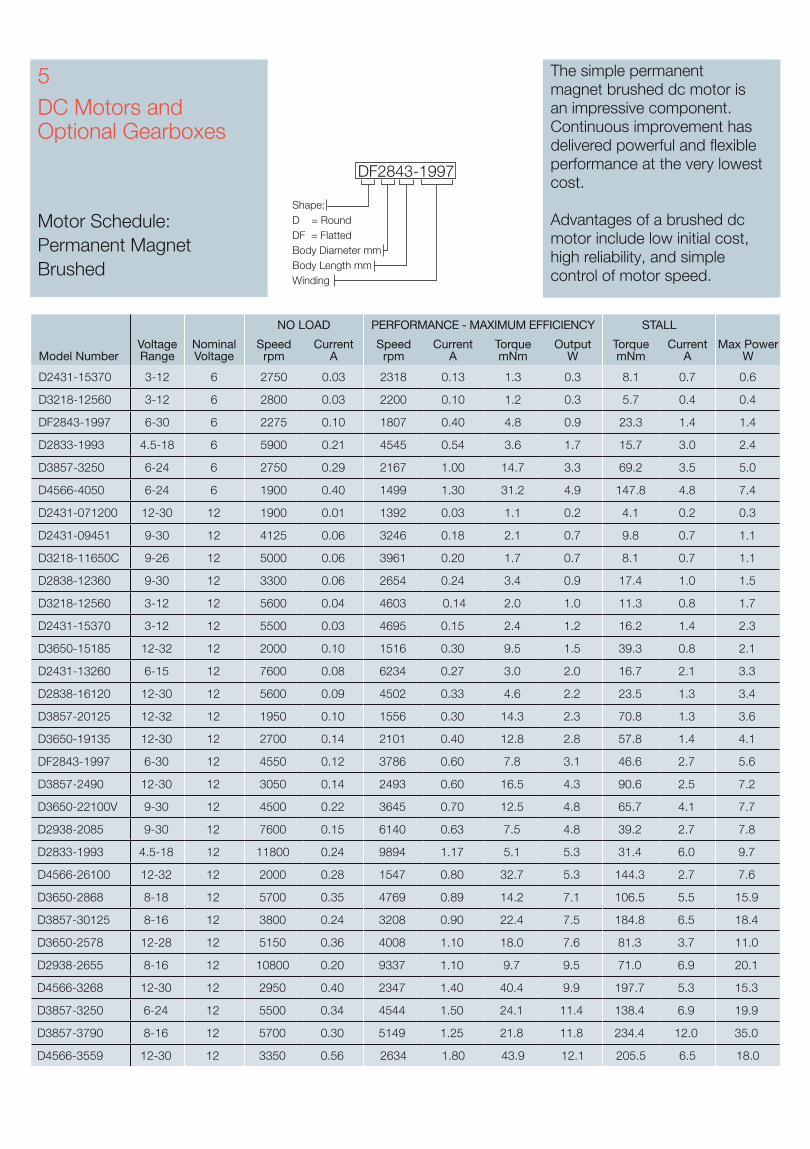
The simple permanent magnet brushed dc motor is an impressive component. Continuous improvement has delivered powerful and flexible performance at the very lowest cost.
Advantages of a brushed dcmotor include low initial cost, high reliability, and simple control of motor speed.
Body Diameter mm
DF2843-1997
WindingBody Length mm
Shape:D = RoundDF = Flatted
5DC Motors and Optional Gearboxes
Motor Schedule: Permanent Magnet Brushed
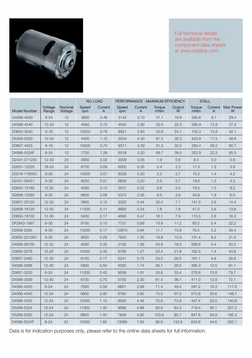
Model NumberVoltage Range
Nominal Voltage
NO LOAD PERFORMANCE - MAXIMUM EFFICIENCY STALL
Max Power W
Speed rpm
Current A
Speed rpm
Current A
Torque mNm
Output W
Torque mNm
Current A
D4566-4050 6-24 12 3800 0.46 3143 2.10 51.1 16.8 295.6 9.7 29.4
D4566-4540 12-24 12 4950 0.72 4042 2.90 52.6 22.3 286.9 12.8 37.2
D3650-3540 8-16 12 10550 0.78 8921 2.83 25.8 24.1 152.3 13.9 42.1
D5269-5030 12-24 12 4400 1.12 3554 4.30 81.5 30.3 423.9 17.5 48.8
D3857-4525 8-16 12 10500 0.70 9311 3.39 31.3 30.5 293.4 28.2 80.7
D4566-5524F 8-24 12 7750 1.28 6318 5.20 59.7 39.5 322.9 22.3 65.5
D2431-071200 12-30 24 3900 0.02 3009 0.05 1.9 0.6 8.5 0.3 0.9
D2631-12520 18-24 24 8700 0.06 6000 0.35 5.4 2.3 17.3 1.2 3.9
D3218-11650C 9-26 24 10000 0.07 8029 0.20 3.2 2.7 16.2 1.4 4.2
D2431-09451 9-30 24 8250 0.07 6600 0.20 3.9 2.7 19.6 1.3 4.2
D3650-15185 12.32 24 4000 0.12 3501 0.22 9.6 3.5 78.5 1.5 8.2
D2838-12360 9-30 24 6600 0.08 5373 0.26 6.5 3.6 34.8 1.9 6.0
D3857-20125 12-32 24 3900 0.12 3320 0.44 20.4 7.1 141.5 2.6 14.4
D2838-16120 12-30 24 11200 0.11 9900 0.54 7.8 7.8 47.0 2.6 13.8
D3650-19135 12-30 24 5400 0.17 4690 0.47 16.1 7.9 115.5 2.8 16.3
DF2843-1997 6-30 24 9100 0.15 7757 0.69 13.8 11.2 93.2 5.4 22.2
D2938-2085 9-30 24 15200 0.17 12870 0.94 11.7 15.8 76.5 5.2 30.4
D3650-22100V 9-30 24 9000 0.28 7643 1.50 19.8 15.9 131.4 8.2 31.0
D4566-26100 12-32 24 4000 0.35 3130 1.26 54.9 18.0 288.6 5.4 30.2
D3650-2578 12.28 24 10300 0.45 8795 1.27 23.4 21.6 162.5 7.4 43.8
D3857-2490 12-30 24 6100 0.17 5241 0.75 23.5 28.5 181.1 4.9 28.9
D4566-3268 12-30 24 5900 0.50 5025 1.74 56.1 29.5 395.3 10.5 61.1
D3857-3250 6-24 24 11000 0.42 9506 1.91 33.6 33.4 276.8 13.8 79.7
D4566-3559 12-30 24 6700 0.70 5700 2.30 61.4 36.1 411.0 12.9 72.1
D4566-4050 6-24 24 7600 0.58 6601 2.69 71.4 49.4 591.2 19.3 117.6
D4566-4540 12-24 24 9900 0.90 8780 3.80 73.5 67.5 573.8 25.6 148.7
D4566-4535 12-24 24 12000 1.10 9300 4.46 75.9 73.9 447.4 22.0 140.6
D5269-5524 12-24 24 11000 1.30 9588 4.88 83.9 84.3 719.4 35.1 207.2
D5269-5030 12-24 24 8800 1.40 7849 4.85 103.6 85.1 847.8 34.9 195.3
D4566-5524F 8-24 24 15500 1.60 13089 7.85 96.9 132.8 645.8 44.6 262.1
Full technical details are available from the component data sheets at www.rotalink.com
Data is for indication purposes only, please refer to the online data sheets for full information.
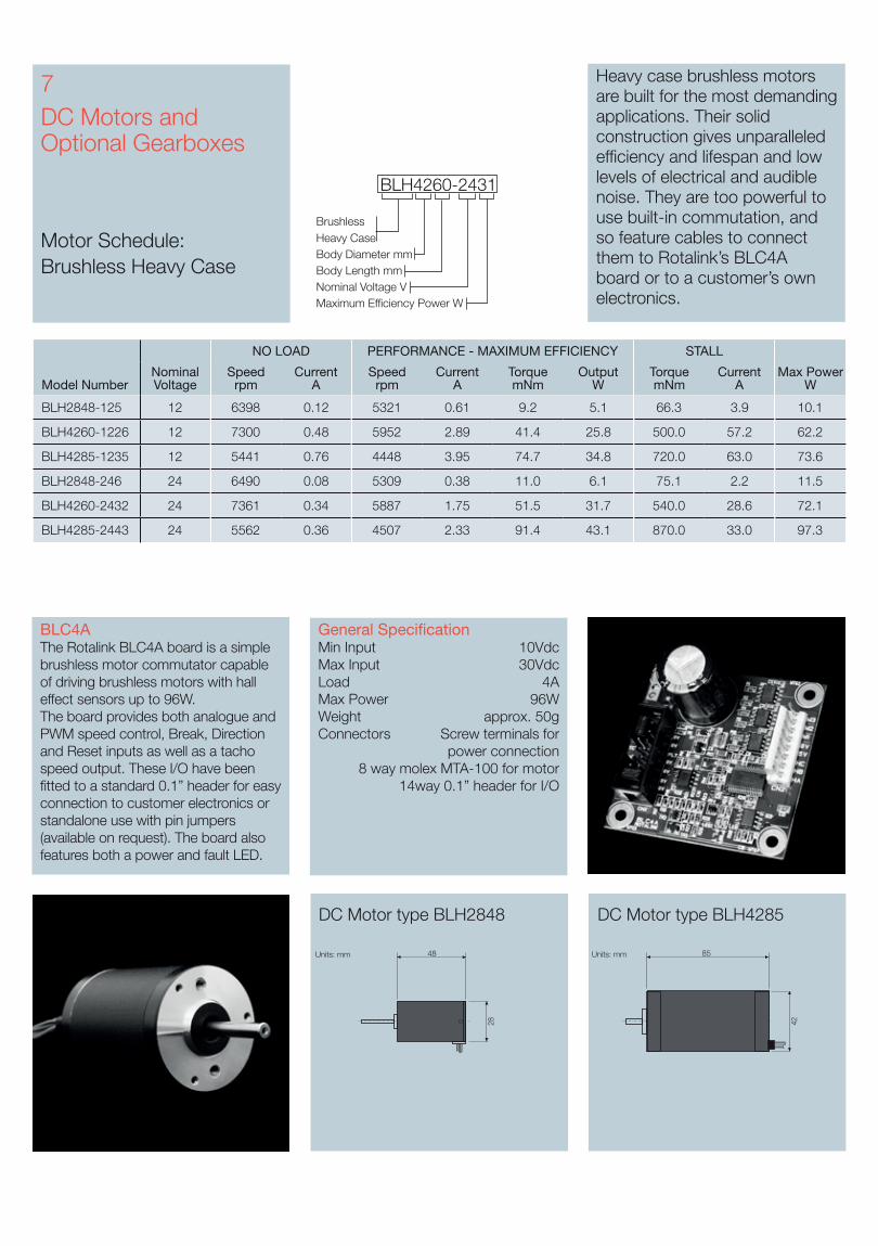
DC Motors and Optional Gearboxes
Motor Schedule: Brushless Heavy Case
7 Heavy case brushless motors are built for the most demanding applications. Their solid construction gives unparalleled efficiency and lifespan and low levels of electrical and audible noise. They are too powerful to use built-in commutation, and so feature cables to connect them to Rotalink’s BLC4A board or to a customer’s own electronics.
Heavy Case
Nominal Voltage VMaximum Efficiency Power W
Body Length mmBody Diameter mm
Brushless
BLH4260-2431
DC Motor type BLH2848 DC Motor type BLH4285
BLC4AThe Rotalink BLC4A board is a simple brushless motor commutator capable of driving brushless motors with hall effect sensors up to 96W.The board provides both analogue and PWM speed control, Break, Direction and Reset inputs as well as a tacho speed output. These I/O have been fitted to a standard 0.1” header for easy connection to customer electronics or standalone use with pin jumpers (available on request). The board also features both a power and fault LED.
General SpecificationMin Input 10VdcMax Input 30VdcLoad 4AMax Power 96WWeight approx. 50gConnectors Screw terminals for
power connection8 way molex MTA-100 for motor
14way 0.1” header for I/O
Model NumberNominal Voltage
NO LOAD PERFORMANCE - MAXIMUM EFFICIENCY STALL
Max Power W
Speed rpm
Current A
Speed rpm
Current A
Torque mNm
Output W
Torque mNm
Current A
BLH2848-125 12 6398 0.12 5321 0.61 9.2 5.1 66.3 3.9 10.1
BLH4260-1226 12 7300 0.48 5952 2.89 41.4 25.8 500.0 57.2 62.2
BLH4285-1235 12 5441 0.76 4448 3.95 74.7 34.8 720.0 63.0 73.6
BLH2848-246 24 6490 0.08 5309 0.38 11.0 6.1 75.1 2.2 11.5
BLH4260-2432 24 7361 0.34 5887 1.75 51.5 31.7 540.0 28.6 72.1
BLH4285-2443 24 5562 0.36 4507 2.33 91.4 43.1 870.0 33.0 97.3
48
28
85
42
Units: mm Units: mm
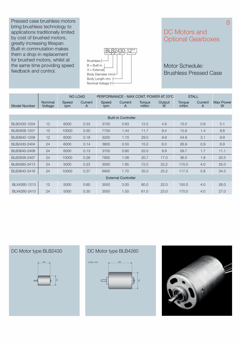
8DC Motors and Optional Gearboxes
Motor Schedule: Brushless Pressed Case
Model NumberNominal Voltage
NO LOAD PERFORMANCE - MAX CONT. POWER AT 23ºC STALL
Max Power W
Speed rpm
Current A
Speed rpm
Current A
Torque mNm
Output W
Torque mNm
Current A
Built-in Controller
BLB2430-1204 12 6000 0.33 3750 0.83 12.5 4.9 15.0 0.9 5.1
BLB2838-1207 12 10000 0.50 7750 1.44 11.7 9.4 15.8 1.4 9.8
BLB3640-1208 12 6000 0.18 3250 1.70 29.0 9.9 54.8 3.1 9.9
BLB2430-2404 24 6000 0.14 3800 0.50 15.0 6.0 26.9 0.9 6.9
BLB3640-2408 24 6000 0.13 3750 0.80 25.0 9.9 59.7 1.7 11.1
BLB2838-2407 24 10000 0.28 7800 1.08 20.7 17.0 36.0 1.8 20.5
BLB4260-2413 24 5000 0.23 3000 1.85 72.0 22.2 170.0 4.0 25.0
BLB3640-2416 24 10000 0.37 6900 1.70 35.0 25.2 117.0 5.8 34.5
External Controller
BLX4260-1213 12 5000 0.60 3500 3.00 60.0 22.0 150.0 4.0 26.0
BLX4260-2413 24 5000 0.30 3550 1.50 61.0 23.0 170.0 4.0 27.0
DC Motor type BLB2430 DC Motor type BLB4260
Pressed case brushless motors bring brushless technology to applications traditionally limited by cost of brushed motors, greatly increasing lifespan. Built-in commutation makes them a drop-in replacement for brushed motors, whilst at the same time providing speed feedback and control. X = External
Nominal Voltage VBody Length mmBody Diameter mm
Brushless
BLB2430-12**
B = Built-in
24 42
Units: mm Units: mm30 59
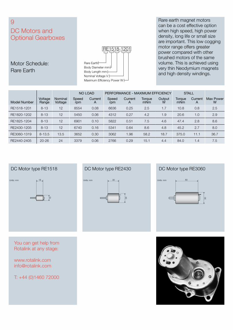
DC Motors and Optional Gearboxes
Motor Schedule: Rare Earth
9 Rare earth magnet motors can be a cost effective option when high speed, high power density, long life or small size are important. This low cogging motor range offers greater power compared with other brushed motors of the same volume. This is achieved using very thin Neodymium magnets and high density windings.
Nominal Voltage VMaximum Efficiency Power W
RE1518-1201
Body Length mmBody Diameter mmRare Earth
DC Motor type RE1518 DC Motor type RE2430 DC Motor type RE3060
18
15
30
24
60
30
Units: mm Units: mm Units: mm
Model NumberVoltage Range
Nominal Voltage
NO LOAD PERFORMANCE - MAXIMUM EFFICIENCY STALL
Max Power W
Speed rpm
Current A
Speed rpm
Current A
Torque mNm
Output W
Torque mNm
Current A
RE1518-1201 8-13 12 8554 0.08 6636 0.25 2.5 1.7 10.8 0.8 2.5
RE1820-1202 8-13 12 5450 0.06 4312 0.27 4.2 1.9 20.6 1.0 2.9
RE1825-1204 8-13 12 6901 0.10 5822 0.51 7.5 4.6 47.4 2.8 8.6
RE2430-1205 8-13 12 6740 0.16 5341 0.64 8.6 4.8 45.2 2.7 8.0
RE3060-1319 8-13.5 13.5 3652 0.30 3062 1.96 58.2 18.7 375.0 11.1 36.7
RE2440-2405 20-26 24 3379 0.06 2766 0.29 15.1 4.4 84.0 1.4 7.5
You can get help from Rotalink at any stage:
T: +44 (0)1460 72000
10DC Motors and Optional Gearboxes
Linear Motion
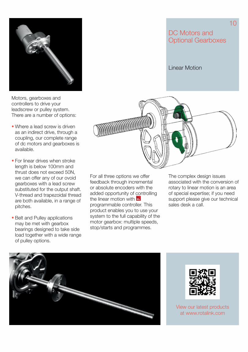
The complex design issues associated with the conversion of rotary to linear motion is an area of special expertise; if you need support please give our technical sales desk a call.
Motors, gearboxes and controllers to drive your leadscrew or pulley system. There are a number of options:
Where a lead screw is driven as an indirect drive, through a coupling, our complete range of dc motors and gearboxes is available.
For linear drives when stroke length is below 100mm and thrust does not exceed 50N, we can offer any of our ovoid gearboxes with a lead screw substituted for the output shaft. V-thread and trapezoidal thread are both available, in a range of pitches.
Belt and Pulley applications may be met with gearbox bearings designed to take side load together with a wide range of pulley options.
For all three options we offer feedback through incremental or absolute encoders with the added opportunity of controlling the linear motion with programmable controller. This product enables you to use your system to the full capability of the motor gearbox: multiple speeds, stop/starts and programmes.
View our latest productsat www.rotalink.com
•
•
•
11DC Motors and Optional Gearboxes
Gearbox Information
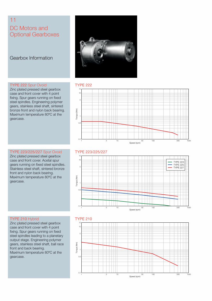
TYPE 223/225/227 TYPE 223/225/227 Spur OvoidZinc plated pressed steel gearbox case and front cover. Acetal spur gears running on fixed steel spindles. Stainless steel shaft, sintered bronze front and nylon back bearing.Maximum temperature 80ºC at the gearcase.
TYPE 222TYPE 222 Spur OvoidZinc plated pressed steel gearbox case and front cover with 4 point fixing. Spur gears running on fixed steel spindles. Engineering polymer gears, stainless steel shaft, sintered bronze front and nylon back bearing. Maximum temperature 80ºC at the gearcase.
TYPE 210 TYPE 210 Hybrid Zinc plated pressed steel gearbox case and front cover with 4 point fixing. Spur gears running on fixed steel spindles leading to a planetary output stage. Engineering polymer gears, stainless steel shaft, ball race front and back bearing. Maximum temperature 80ºC at the gearcase.
Speed (rpm)
Torq
ue (N
m)
1 5 10 50 100 500 10000.1
0.5
1
5
10
15
Speed (rpm)
Torq
ue (N
m)
1 5 10 50 100 500 10000.1
0.5
1
5
10
15
Speed (rpm)
Torq
ue (N
m)
1 5 10 50 100 500 10000.1
0.5
1
5
10
15
TYPE 223TYPE 225TYPE 227
Ratio
25:4 80:1 750:1 10000:1
20:3 100:1 900:1 15000:1
25:3 125:1 1000:1 30000:1
10:1 150:1 1500:1 60000:1
15:1 200:1 2000:1 90000:1
20:1 250:1 3000:1 120000:1
30:1 300:1 4000:1 180000:1
40:1 400:1 5000:1 360000:1
50:1 500:1 6000:1 720000:1
60:1 600:1 7500:1
TYPE 225TYPE 223 TYPE 227
TYPE 222
TYPE 210
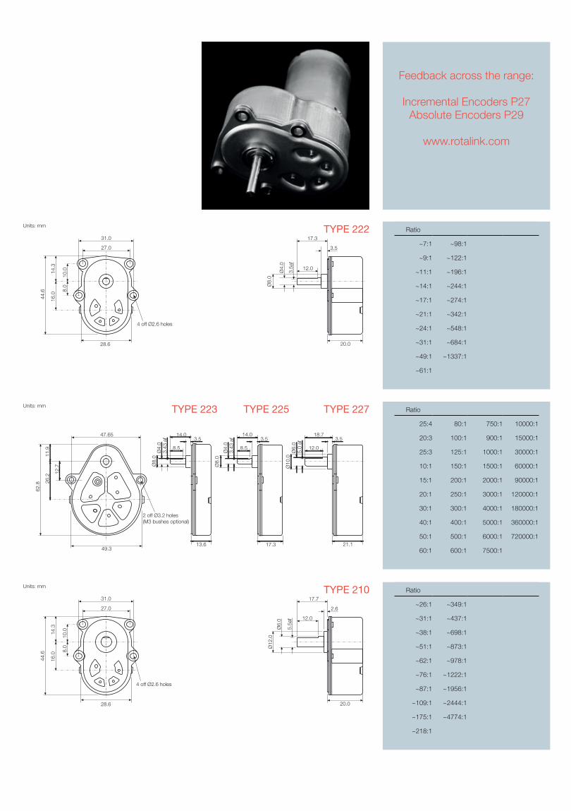
Feedback across the range:
Incremental Encoders P27Absolute Encoders P29
www.rotalink.com
Units: mm
8.0
27.0
31.0
10.0
28.6
14.3
16.0
44.6
4 off Ø2.6 holes
3.5
20.0
Ø8.
0
3.5a
f
Ø4.
0
12.0
17.3
Units: mm
8.0
27.0
31.0
10.0
28.6
14.3
16.0
44.6
4 off Ø2.6 holes
2.6
Ø12
.0
5.5a
f
Ø6.
0
20.0
12.0
17.7
Ratio
~7:1 ~98:1
~9:1 ~122:1
~11:1 ~196:1
~14:1 ~244:1
~17:1 ~274:1
~21:1 ~342:1
~24:1 ~548:1
~31:1 ~684:1
~49:1 ~1337:1
~61:1
Ratio
~26:1 ~349:1
~31:1 ~437:1
~38:1 ~698:1
~51:1 ~873:1
~62:1 ~978:1
~76:1 ~1222:1
~87:1 ~1956:1
~109:1 ~2444:1
~175:1 ~4774:1
~218:1
Units: mm
13.6
14.03.5
Ø4.
0Ø
8.0
3.43
af
8.5
17.3
14.03.5
Ø4.
03.
43 a
f
8.5
Ø8.
0
21.1
3.5
Ø6.
0Ø
10.0
5.0
af
18.7
12.0
49.3
2 off Ø3.2 holes(M3 bushes optional)
62.8
11.9
26.2
12.7
47.65
13DC Motors and Optional Gearboxes
Gearbox Information
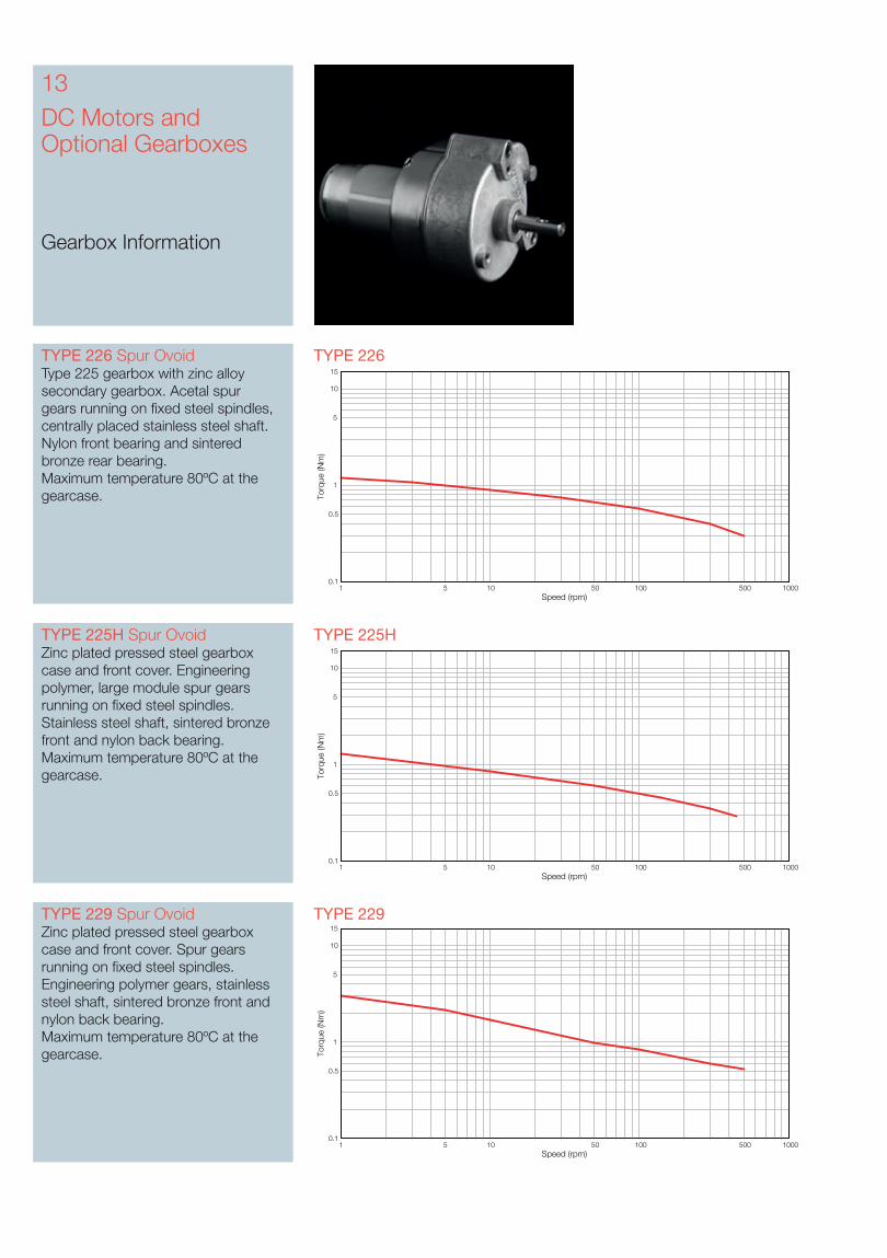
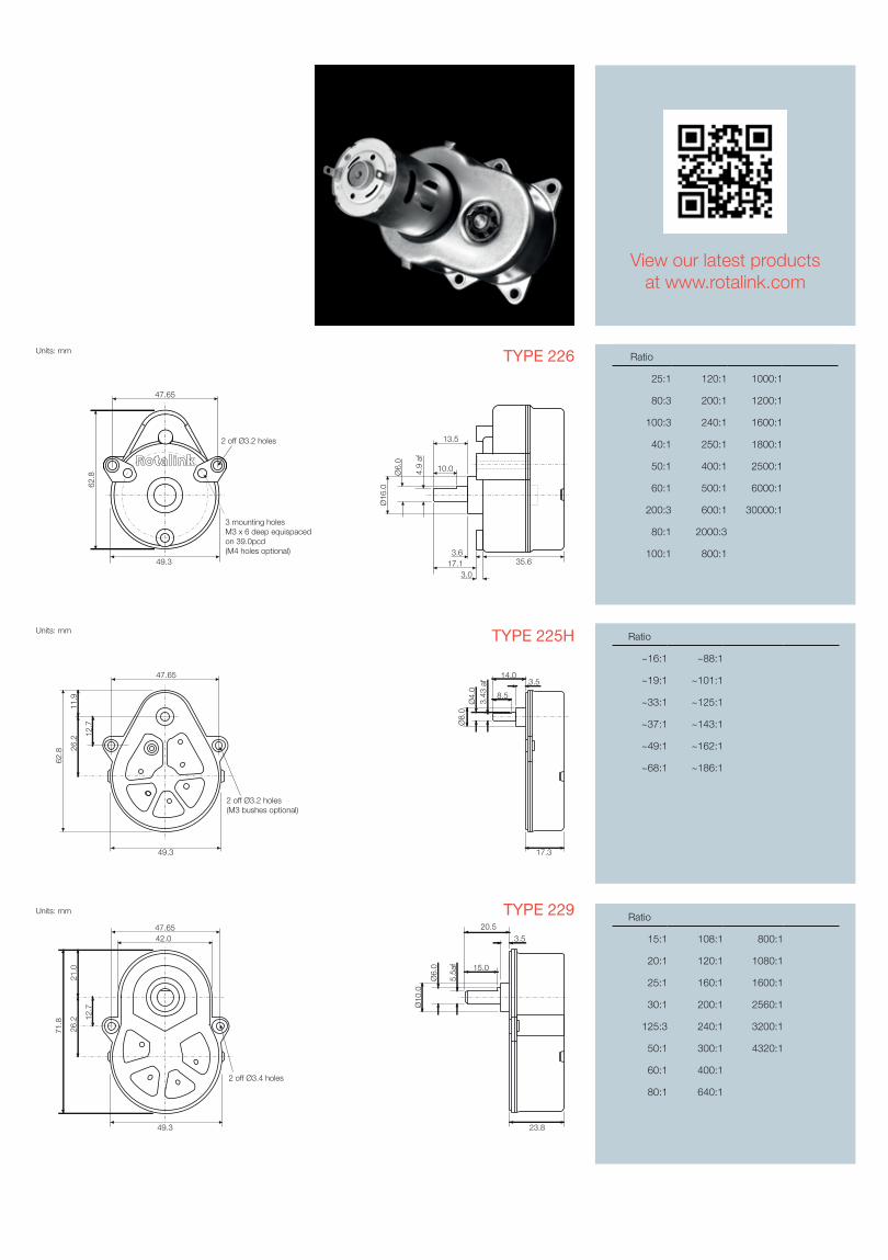
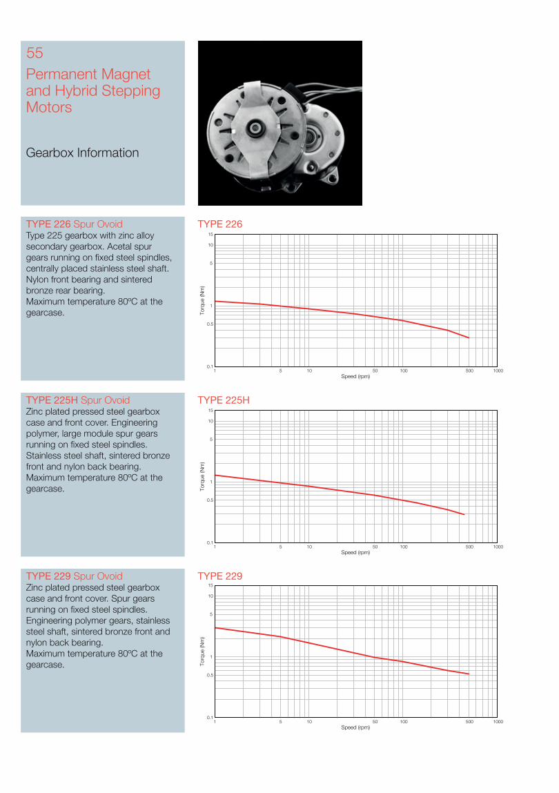
TYPE 226TYPE 226 Spur OvoidType 225 gearbox with zinc alloy secondary gearbox. Acetal spur gears running on fixed steel spindles, centrally placed stainless steel shaft. Nylon front bearing and sintered bronze rear bearing. Maximum temperature 80ºC at the gearcase.
TYPE 225HTYPE 225H Spur OvoidZinc plated pressed steel gearbox case and front cover. Engineering polymer, large module spur gears running on fixed steel spindles. Stainless steel shaft, sintered bronze front and nylon back bearing.Maximum temperature 80ºC at the gearcase.
Speed (rpm)
Torq
ue (N
m)
1 5 10 50 100 500 10000.1
0.5
1
5
10
15
Speed (rpm)
Torq
ue (N
m)
1 5 10 50 100 500 10000.1
0.5
1
5
10
15
TYPE 229TYPE 229 Spur OvoidZinc plated pressed steel gearbox case and front cover. Spur gears running on fixed steel spindles. Engineering polymer gears, stainless steel shaft, sintered bronze front and nylon back bearing. Maximum temperature 80ºC at the gearcase.
Speed (rpm)
Torq
ue (N
m)
1 5 10 50 100 500 10000.1
0.5
1
5
10
15
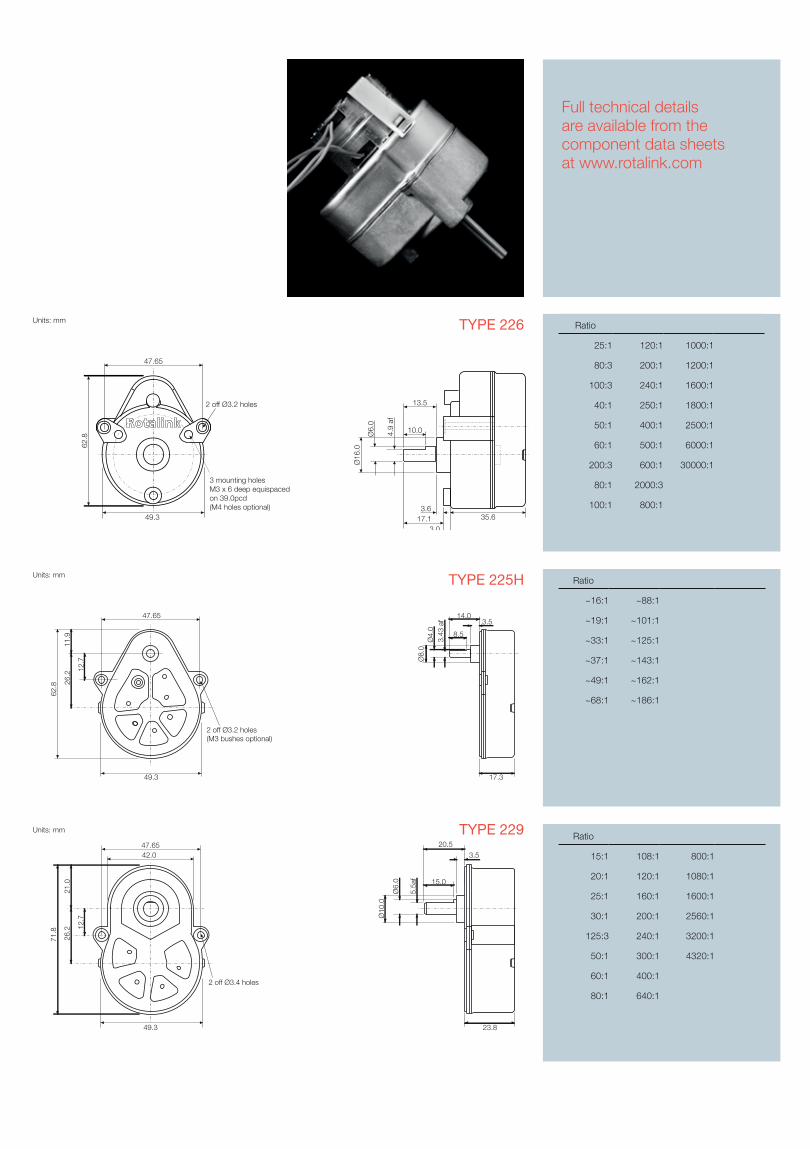
Ratio
25:1 120:1 1000:1
80:3 200:1 1200:1
100:3 240:1 1600:1
40:1 250:1 1800:1
50:1 400:1 2500:1
60:1 500:1 6000:1
200:3 600:1 30000:1
80:1 2000:3
100:1 800:1
TYPE 226
Ratio
~16:1 ~88:1
~19:1 ~101:1
~33:1 ~125:1
~37:1 ~143:1
~49:1 ~162:1
~68:1 ~186:1
TYPE 225H
View our latest productsat www.rotalink.com
Units: mm
47.65
62.8
49.3
2 off Ø3.2 holes
3 mounting holes M3 x 6 deep equispaced on 39.0pcd(M4 holes optional)
Ø16
.0
35.6
Ø6.
0
4.9
af
13.5
10.0
17.13.0
3.6
Units: mm
49.3
2 off Ø3.4 holes
26.2 12
.7
47.6542.0
71.8
21.0
23.8
20.5
3.5
Ø10
.0
5.5a
f
Ø6.
0 15.0
TYPE 229 Ratio
15:1 108:1 800:1
20:1 120:1 1080:1
25:1 160:1 1600:1
30:1 200:1 2560:1
125:3 240:1 3200:1
50:1 300:1 4320:1
60:1 400:1
80:1 640:1
Units: mm
17.3
14.03.5
Ø8.
0Ø
4.0
3.43
af
8.5
49.3
2 off Ø3.2 holes(M3 bushes optional)
62.8
11.9
26.2
12.7
47.65
15DC Motors and Optional Gearboxes
Gearbox Information
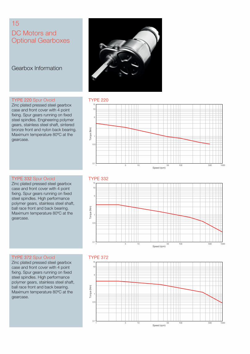
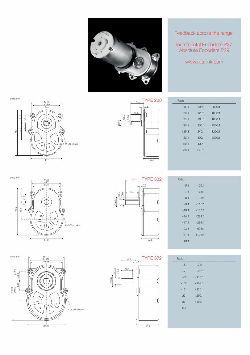
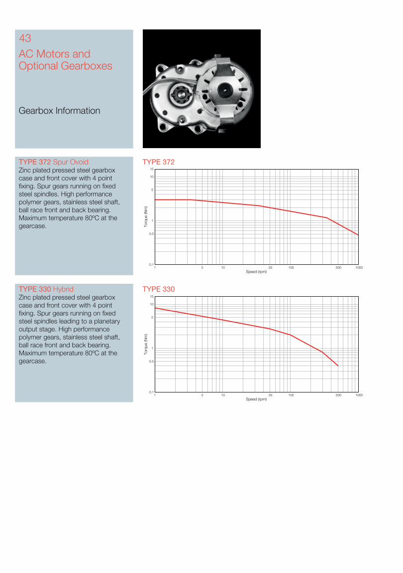
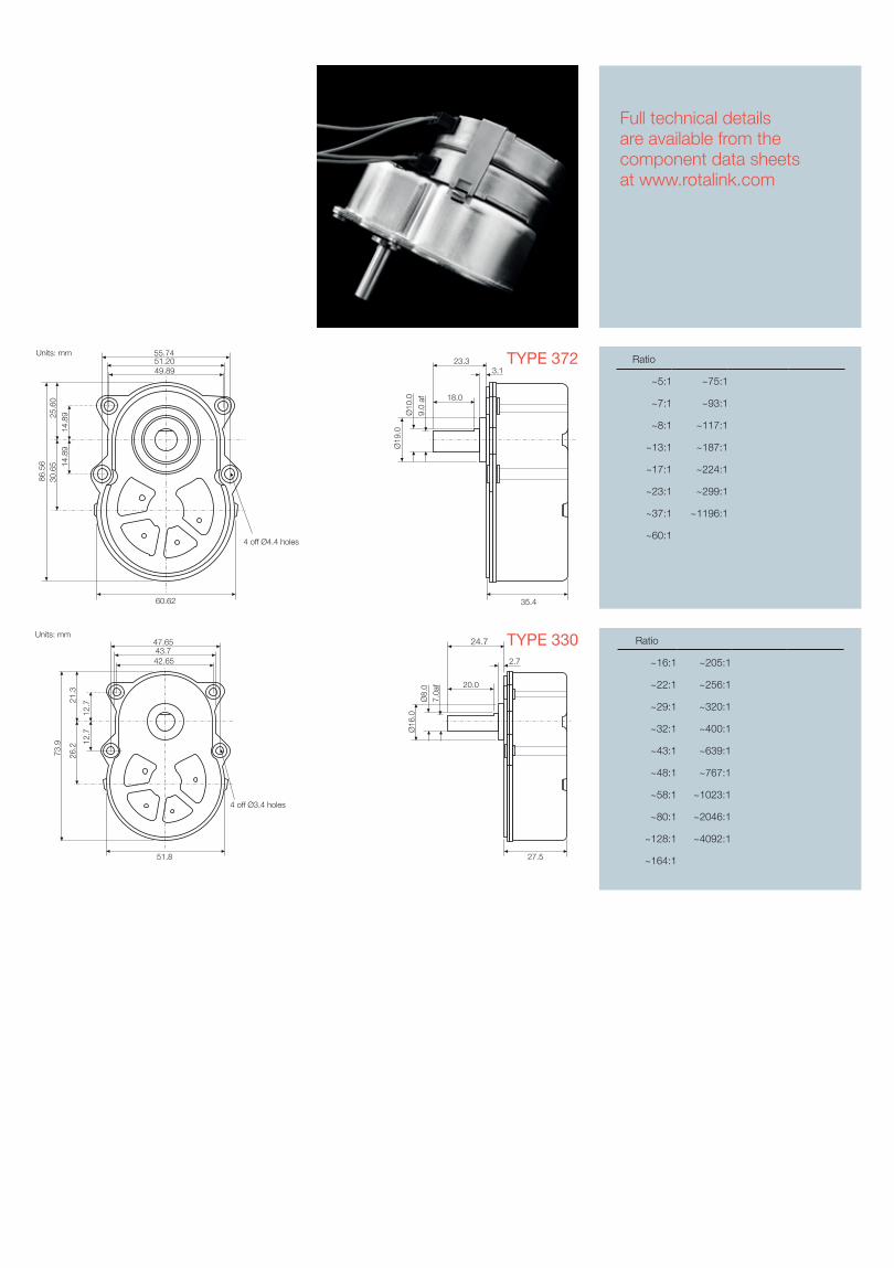
TYPE 372TYPE 372 Spur OvoidZinc plated pressed steel gearbox case and front cover with 4 point fixing. Spur gears running on fixed steel spindles. High performance polymer gears, stainless steel shaft, ball race front and back bearing. Maximum temperature 80ºC at the gearcase.
Speed (rpm)
Torq
ue (N
m)
1 5 10 50 100 500 10000.1
0.5
1
5
10
15
TYPE 332TYPE 332 Spur OvoidZinc plated pressed steel gearbox case and front cover with 4 point fixing. Spur gears running on fixed steel spindles. High performance polymer gears, stainless steel shaft, ball race front and back bearing. Maximum temperature 80ºC at the gearcase.
Speed (rpm)
Torq
ue (N
m)
1 5 10 50 100 500 10000.1
0.5
1
5
10
15
TYPE 220TYPE 220 Spur OvoidZinc plated pressed steel gearbox case and front cover with 4 point fixing. Spur gears running on fixed steel spindles. Engineering polymer gears, stainless steel shaft, sintered bronze front and nylon back bearing. Maximum temperature 80ºC at the gearcase.
Speed (rpm)
Torq
ue (N
m)
1 5 10 50 100 500 10000.1
0.5
1
5
10
15
55.7451.2049.89
60.62
25.6
014
.89
14.8
930
.65
86.5
6
35.4
23.33.1
18.0
Ø19
.0Ø
10.0
9.0
af
Units: mm
4 off Ø4.4 holes
Ratio
~5:1 ~75:1
~7:1 ~93:1
~8:1 ~117:1
~13:1 ~187:1
~17:1 ~224:1
~23:1 ~299:1
~37:1 ~1196:1
~60:1
TYPE 372
Feedback across the range:
Incremental Encoders P27Absolute Encoders P29
www.rotalink.com
TYPE 332Units: mm47.6543.742.65
51.8
21.3
12.7
12.7
26.2
73.9
27.5
24.7
2.7
20.0
Ø16
.0
Ø8.
07.
0af
4 off Ø3.4 holes
Ratio
~5:1 ~60:1
~7:1 ~75:1
~8:1 ~93:1
~9:1 ~117:1
~13:1 ~187:1
~14:1 ~224:1
~17:1 ~299:1
~23:1 ~598:1
~37:1 ~1196:1
~48:1
TYPE 220 Ratio
15:1 108:1 800:1
20:1 120:1 1080:1
25:1 160:1 1600:1
30:1 200:1 2560:1
125:3 240:1 3200:1
50:1 300:1 4320:1
60:1 400:1
80:1 640:1
Units: mm
49.3
4 off Ø3.4 holes
26.2 12
.7
47.65
42.0
71.8
21.0
42.65
12.7
23.8
3.5
Ø10
.0
5.5a
f
Ø6.
0
15.0
20.5
17DC Motors and Optional Gearboxes
Gearbox Information
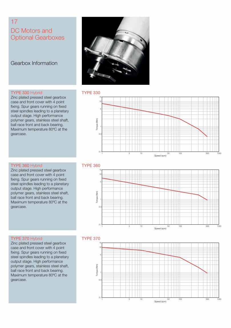
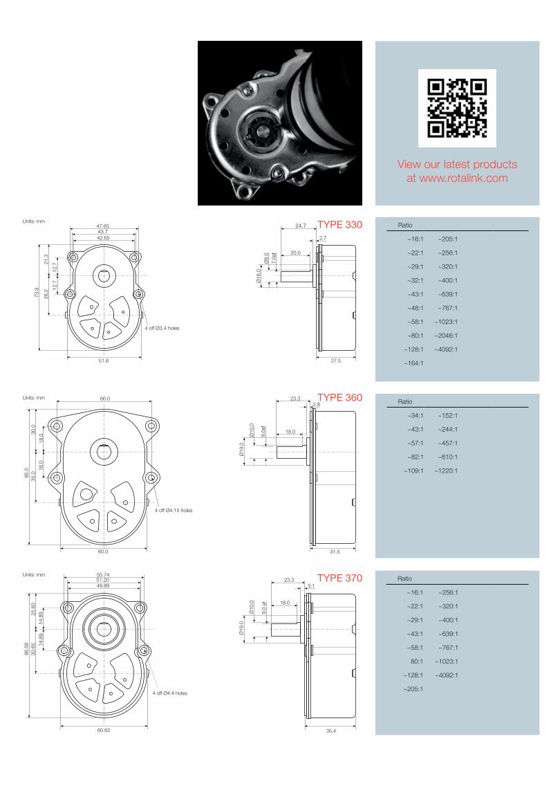
TYPE 330 TYPE 330 HybridZinc plated pressed steel gearbox case and front cover with 4 point fixing. Spur gears running on fixed steel spindles leading to a planetary output stage. High performance polymer gears, stainless steel shaft, ball race front and back bearing. Maximum temperature 80ºC at the gearcase.
TYPE 370TYPE 370 HybridZinc plated pressed steel gearbox case and front cover with 4 point fixing. Spur gears running on fixed steel spindles leading to a planetary output stage. High performance polymer gears, stainless steel shaft, ball race front and back bearing. Maximum temperature 80ºC at the gearcase.
Speed (rpm)
Torq
ue (N
m)
1 5 10 50 100 500 10000.1
0.5
1
5
10
15
Speed (rpm)
Torq
ue (N
m)
1 5 10 50 100 500 10000.1
0.5
1
5
10
15
TYPE 360 HybridZinc plated pressed steel gearbox case and front cover with 4 point fixing. Spur gears running on fixed steel spindles leading to a planetary output stage. High performance polymer gears, stainless steel shaft, ball race front and back bearing. Maximum temperature 80ºC at the gearcase.
TYPE 360
Speed (rpm)
Torq
ue (N
m)
1 5 10 50 100 500 10000.1
0.5
1
5
10
15
TYPE 360
TYPE 330
View our latest productsat www.rotalink.com
Units: mm47.6543.742.65
51.8
21.3
12.7
12.7
26.2
73.9
27.5
24.7
2.7
20.0Ø
16.0
Ø8.
07.
0af
4 off Ø3.4 holes
Ratio
~16:1 ~256:1
~22:1 ~320:1
~29:1 ~400:1
~43:1 ~639:1
~58:1 ~767:1
80:1 ~1023:1
~128:1 ~4092:1
~205:1
TYPE 37055.7451.2049.89
60.62
25.6
0
14.8
914
.89
30.6
586
.56
35.4
23.33.1
18.0
Ø19
.0
Ø10
.0
9.0
af
Units: mm
4 off Ø4.4 holes
Ratio
~16:1 ~205:1
~22:1 ~256:1
~29:1 ~320:1
~32:1 ~400:1
~43:1 ~639:1
~48:1 ~767:1
~58:1 ~1023:1
~80:1 ~2046:1
~128:1 ~4092:1
~164:1
Ratio
~34:1 ~152:1
~43:1 ~244:1
~57:1 ~457:1
~82:1 ~610:1
~109:1 ~1220:1
30.0
4 off Ø4.15 holes
66.0
60.0
95.0 18
.018
.0
35.0
Units: mm2.8
23.3
18.0
Ø10
.0
9.0a
f
Ø19
.0
31.5
Units: mm
Ø24.0
3 off M2.5 holes equispaced on 15 pcd
1.1
22.35
1.6
2.3
14.010
.0
8.03.5
af
Ø4.
0
Units: mm
Ø24.0
3 off M2.5 holes equispaced on 15 pcd
1.1
29.30
1.6
2.3
14.0
10.0
8.03.5
af
Ø4.
0
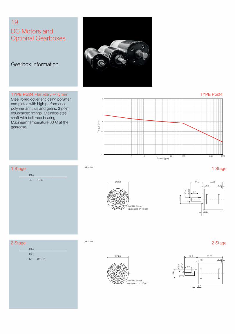
19DC Motors and Optional Gearboxes
Gearbox Information
TYPE PG24TYPE PG24 Planetary PolymerSteel rolled cover enclosing polymer end plates with high performance polymer annulus and gears. 3 point equispaced fixings. Stainless steel shaft with ball race bearing.Maximum temperature 80ºC at the gearcase.
Speed (rpm)
Torq
ue (N
m)
1 5 10 50 100 500 10000.1
0.5
1
5
1 Stage
2 StageRatio
13:1
~17:1 (351:21)
1 Stage
2 Stage
Ratio
~4:1 (13:3)
Units: mm
Ø24.0
3 off M2.5 holes equispaced on 15 pcd
1.1
36.25
1.6
2.3
14.0
10.0
8.03.5
af
Ø4.
0
Units: mm
Ø24.0
3 off M2.5 holes equispaced on 15 pcd
1.1
43.20
1.6
2.3
14.0
10.0
8.03.5
af
Ø4.
0
Units: mm
Ø24.0
3 off M2.5 holes equispaced on 15 pcd
1.1
50.15
1.6
2.3
14.0
10.0
8.03.5
af
Ø4.
0
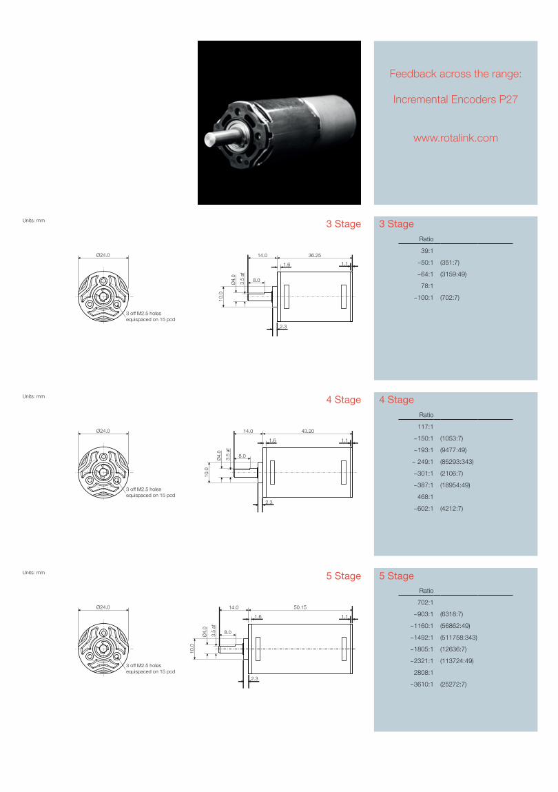
3 Stage
Feedback across the range:
Incremental Encoders P27
www.rotalink.com
3 Stage
4 Stage
5 Stage
4 Stage
5 Stage
Ratio
39:1
~50:1 (351:7)
~64:1 (3159:49)
78:1
~100:1 (702:7)
Ratio
117:1
~150:1 (1053:7)
~193:1 (9477:49)
~ 249:1 (85293:343)
~301:1 (2106:7)
~387:1 (18954:49)
468:1
~602:1 (4212:7)
Ratio
702:1
~903:1 (6318:7)
~1160:1 (56862:49)
~1492:1 (511758:343)
~1805:1 (12636:7)
~2321:1 (113724:49)
2808:1
~3610:1 (25272:7)
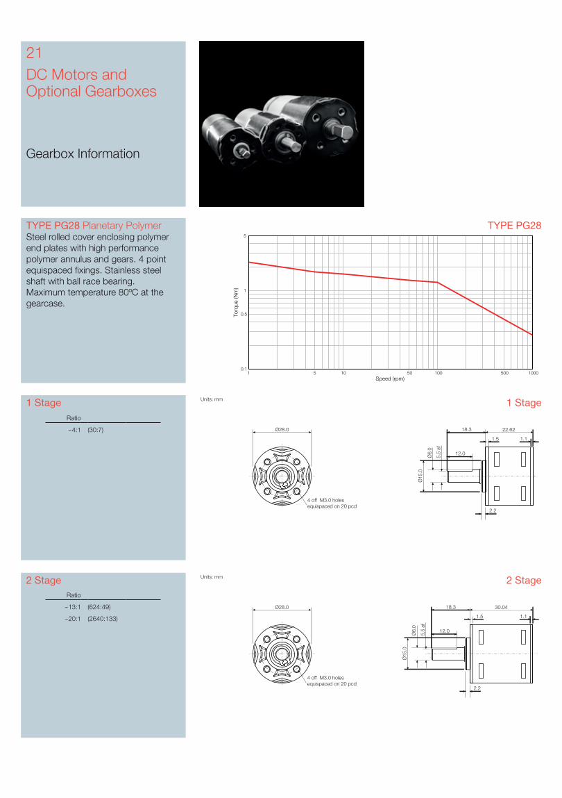
21DC Motors and Optional Gearboxes
Gearbox Information
TYPE PG28TYPE PG28 Planetary PolymerSteel rolled cover enclosing polymer end plates with high performance polymer annulus and gears. 4 point equispaced fixings. Stainless steel shaft with ball race bearing.Maximum temperature 80ºC at the gearcase.
Speed (rpm)
Torq
ue (N
m)
1 5 10 50 100 500 10000.1
0.5
1
5
1 Stage
2 StageRatio
~13:1 (624:49)
~20:1 (2640:133)
Ratio
~4:1 (30:7)
1 Stage
2 Stage
Units: mm
Ø28.0
4 off M3.0 holes equispaced on 20 pcd
1.1
22.62
1.5
18.3
12.05.5
af
Ø6.
0
Ø15
.0
2.2
Units: mm
Ø28.0
4 off M3.0 holes equispaced on 20 pcd
1.1
30.04
1.5
18.3
12.05.5
af
Ø6.
0
Ø15
.0
2.2
3 Stage
View our latest productsat www.rotalink.com
4 Stage
5 Stage
Ratio
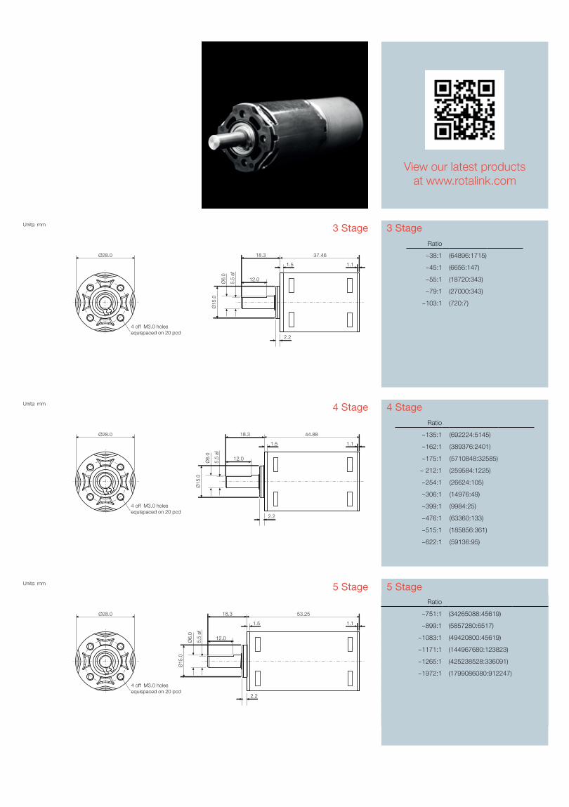
~135:1 (692224:5145)
~162:1 (389376:2401)
~175:1 (5710848:32585)
~ 212:1 (259584:1225)
~254:1 (26624:105)
~306:1 (14976:49)
~399:1 (9984:25)
~476:1 (63360:133)
~515:1 (185856:361)
~622:1 (59136:95)
Ratio
~751:1 (34265088:45619)
~899:1 (5857280:6517)
~1083:1 (49420800:45619)
~1171:1 (144967680:123823)
~1265:1 (425238528:336091)
~1972:1 (1799086080:912247)
3 StageRatio
~38:1 (64896:1715)
~45:1 (6656:147)
~55:1 (18720:343)
~79:1 (27000:343)
~103:1 (720:7)
4 Stage
5 Stage
Units: mm
Ø28.0
4 off M3.0 holes equispaced on 20 pcd
1.1
37.46
1.5
18.3
12.05.5
af
Ø6.
0
Ø15
.0
2.2
Units: mm
Ø28.0
4 off M3.0 holes equispaced on 20 pcd
1.1
44.88
1.5
18.3
12.05.5
af
Ø6.
0
Ø15
.0
2.2
Units: mm
Ø28.0
4 off M3.0 holes equispaced on 20 pcd
1.1
53.25
1.5
18.3
12.05.5
af
Ø6.
0
Ø15
.0
2.2
23DC Motors and Optional Gearboxes
Gearbox Information
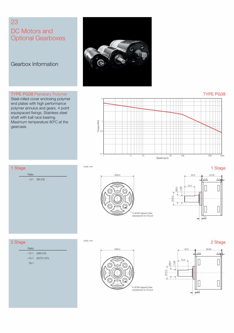
TYPE PG38 Planetary PolymerSteel rolled cover enclosing polymer end plates with high performance polymer annulus and gears. 4 point equispaced fixings. Stainless steel shaft with ball race bearing.Maximum temperature 80ºC at the gearcase.
TYPE PG38
Speed (rpm)
Torq
ue (N
m)
1 5 10 50 100 500 10000.1
0.5
1
5
1 Stage
2 StageRatio
~12:1 (285:23)
~15:1 (2375:161)
19:1
Ratio
~4:1 (95:23)
1 Stage
2 StageUnits: mm
Ø38.0
4 off M4 tapped holes equispaced on 25 pcd
1.1
30.60
Ø15
.0
Ø8.
0
7.0a
f
20.0
12.0
1.5
3.0
Units: mm
Ø38.0
4 off M4 tapped holes equispaced on 25 pcd
1.1
23.05Ø
15.0
Ø8.
0
7.0a
f
20.0
12.0
1.5
3.0
3 Stage
Feedback across the range:
Incremental Encoders P27
www.rotalink.com
4 Stage
5 Stage
Ratio
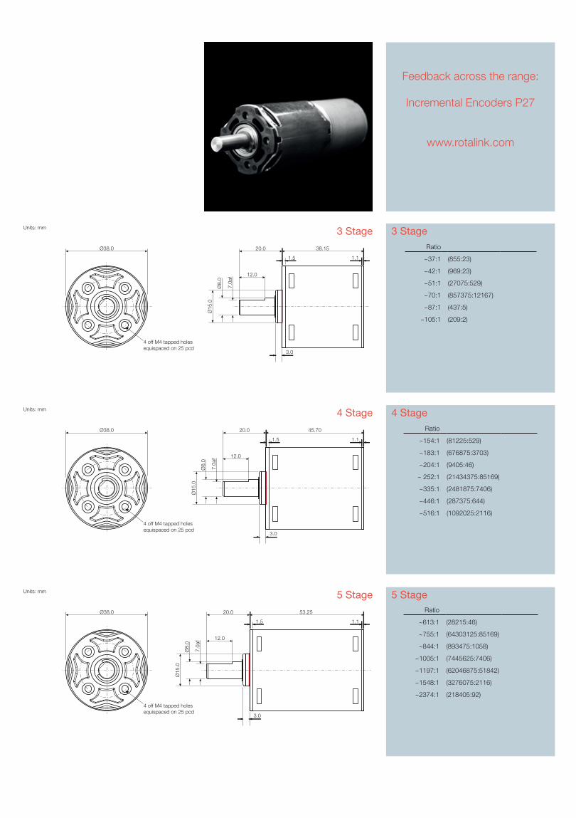
~154:1 (81225:529)
~183:1 (676875:3703)
~204:1 (9405:46)
~ 252:1 (21434375:85169)
~335:1 (2481875:7406)
~446:1 (287375:644)
~516:1 (1092025:2116)
Ratio
~613:1 (28215:46)
~755:1 (64303125:85169)
~844:1 (893475:1058)
~1005:1 (7445625:7406)
~1197:1 (62046875:51842)
~1548:1 (3276075:2116)
~2374:1 (218405:92)
3 StageRatio
~37:1 (855:23)
~42:1 (969:23)
~51:1 (27075:529)
~70:1 (857375:12167)
~87:1 (437:5)
~105:1 (209:2)
4 Stage
5 StageUnits: mm
Ø38.0
4 off M4 tapped holes equispaced on 25 pcd
1.1
53.25
Ø15
.0
Ø8.
0
7.0a
f
20.0
12.0
1.5
3.0
Units: mm
Ø38.0
4 off M4 tapped holes equispaced on 25 pcd
1.1
45.70
Ø15
.0
Ø8.
0
7.0a
f
20.0
12.0
1.5
3.0
Units: mm
Ø38.0
4 off M4 tapped holes equispaced on 25 pcd
1.1
38.15
Ø15
.0
Ø8.
0
7.0a
f
20.0
12.0
1.5
3.0
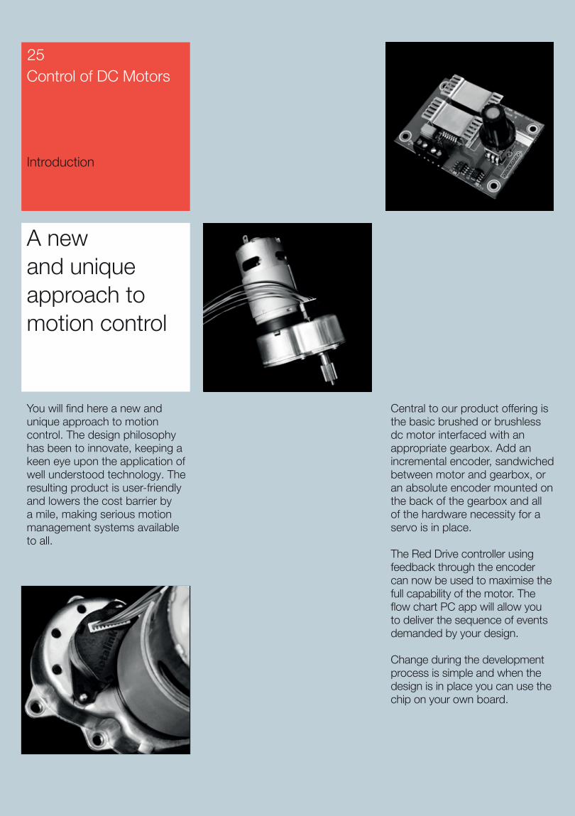
Central to our product offering is the basic brushed or brushless dc motor interfaced with an appropriate gearbox. Add an incremental encoder, sandwiched between motor and gearbox, or an absolute encoder mounted on the back of the gearbox and all of the hardware necessity for a servo is in place.
The Red Drive controller using feedback through the encoder can now be used to maximise the full capability of the motor. The flow chart PC app will allow you to deliver the sequence of events demanded by your design.
Change during the development process is simple and when the design is in place you can use the chip on your own board.
A new and unique approach to motion control
You will find here a new and unique approach to motion control. The design philosophy has been to innovate, keeping a keen eye upon the application of well understood technology. The resulting product is user-friendly and lowers the cost barrier by a mile, making serious motion management systems available to all.
Control of DC Motors
Introduction
25
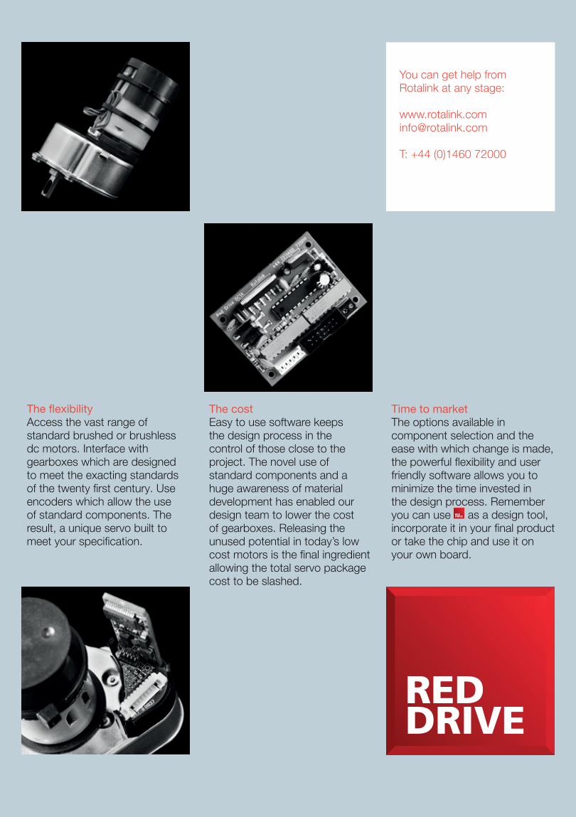
The flexibility Access the vast range of standard brushed or brushless dc motors. Interface with gearboxes which are designed to meet the exacting standards of the twenty first century. Use encoders which allow the use of standard components. The result, a unique servo built to meet your specification.
The cost Easy to use software keeps the design process in the control of those close to the project. The novel use of standard components and a huge awareness of material development has enabled our design team to lower the cost of gearboxes. Releasing the unused potential in today’s low cost motors is the final ingredient allowing the total servo package cost to be slashed.
Time to market The options available in component selection and the ease with which change is made, the powerful flexibility and user friendly software allows you to minimize the time invested in the design process. Remember you can use as a design tool, incorporate it in your final product or take the chip and use it on your own board.
You can get help from Rotalink at any stage:
T: +44 (0)1460 72000

In order to support OEMs in their determination to maintain a competitive edge we have developed an ASIC based dual channel encoder. It uses capacitive sensing, which delivers cost effective feedback whilst minimizing size.
The capacitive design and custom ASIC, means the encoder can successfully operate over a wide range of temperatures and is unaffected by external magnetic forces. The ASIC has internal amplification and can directly drive TTL logic.
Various options of the encoder are available from 8ppr single channel to 24ppr dual channel (giving 48 positions per rev with signal processing).
A 300mm loom is available to link the encoder to a standard 2.54mm pitch 4-way PCB header. In full production the encoder connector allows customers to easily use a loom tailored to their requirements.
Customers should be aware of the opportunity of using the single or dual channel encoder with our programmable controller Red Drive which offers the real opportunity of low cost servo systems.
Control of DC Motors
Incremental Encoder
27
Innovative encoder options that save space
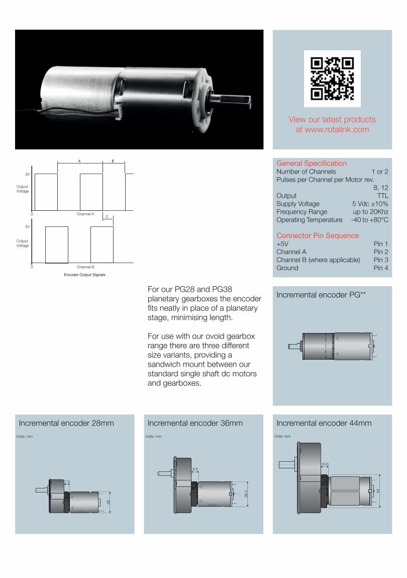
General SpecificationNumber of Channels 1 or 2Pulses per Channel per Motor rev.
8, 12Output TTLSupply Voltage 5 Vdc ±10%Frequency Range up to 20Khz Operating Temperature -40 to +80°C
Connector Pin Sequence+5V Pin 1Channel A Pin 2Channel B (where applicable) Pin 3Ground Pin 4
For our PG28 and PG38 planetary gearboxes the encoder fits neatly in place of a planetary stage, minimising length.
For use with our ovoid gearbox range there are three different size variants, providing a sandwich mount between our standard single shaft dc motors and gearboxes.
Channel A0
5V
OutputVoltage
Encoder Output Signals
Channel B0
5V
OutputVoltage
A B
C
Incremental encoder 36mmIncremental encoder 28mm Incremental encoder 44mm
View our latest productsat www.rotalink.com
7.5
9.3
36.4
10.0
44
Units: mm Units: mm Units: mm
28
Incremental encoder PG**
Mechanical Absolute Encoder
Magnetic Absolute Encoder
Control of DC Motors
Absolute Encoders
29
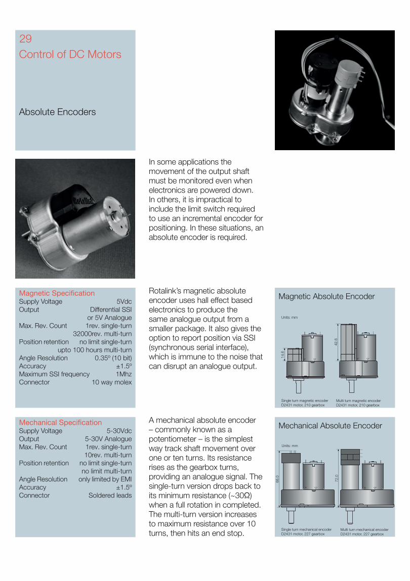
A mechanical absolute encoder – commonly known as a potentiometer – is the simplest way track shaft movement over one or ten turns. Its resistance rises as the gearbox turns, providing an analogue signal. The single-turn version drops back to its minimum resistance (~30Ω) when a full rotation in completed. The multi-turn version increases to maximum resistance over 10 turns, then hits an end stop.
In some applications the movement of the output shaft must be monitored even when electronics are powered down. In others, it is impractical to include the limit switch required to use an incremental encoder for positioning. In these situations, an absolute encoder is required.
Mechanical SpecificationSupply Voltage 5-30VdcOutput 5-30V AnalogueMax. Rev. Count 1rev. single-turn 10rev. multi-turnPosition retention no limit single-turn
no limit multi-turnAngle Resolution only limited by EMIAccuracy ±1.5ºConnector Soldered leads
Rotalink’s magnetic absolute encoder uses hall effect based electronics to produce the same analogue output from a smaller package. It also gives the option to report position via SSI (synchronous serial interface), which is immune to the noise that can disrupt an analogue output.
14.6
Units: mm
42.6
Single turn magnetic encoderD2431 motor, 210 gearbox
Multi turn magnetic encoderD2431 motor, 210 gearbox
66.0
72.0
Units: mm
Single turn mechanical encoderD2431 motor, 227 gearbox
Multi turn mechanical encoderD2431 motor, 227 gearbox
Magnetic SpecificationSupply Voltage 5VdcOutput Differential SSI
or 5V AnalogueMax. Rev. Count 1rev. single-turn 32000rev. multi-turnPosition retention no limit single-turn
upto 100 hours multi-turnAngle Resolution 0.35º (10 bit)Accuracy ±1.5ºMaximum SSI frequency 1MhzConnector 10 way molex
30Control of DC Motors
Electromagnetic Interference
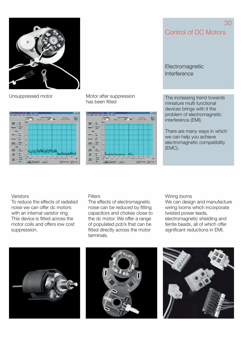
The increasing trend towards miniature multi functional devices brings with it the problem of electromagnetic interference (EMI).
There are many ways in which we can help you achieve electromagnetic compatibility (EMC).
VaristorsTo reduce the effects of radiated noise we can offer dc motors with an internal varistor ring. This device is fitted across the motor coils and offers low cost suppression.
FiltersThe effects of electromagnetic noise can be reduced by fitting capacitors and chokes close to the dc motor. We offer a range of populated pcb’s that can be fitted directly across the motor terminals.
Wiring loomsWe can design and manufacture wiring looms which incorporate twisted power leads, electromagnetic shielding and ferrite beads, all of which offer significant reductions in EMI.
Unsuppressed motor Motor after suppression has been fitted
The board was designedwith cost at the forefront of thespecification and manufacturedin volumes that deliver thispromise.
Use Red Drive throughout theproduct development process.
• Write your own programs and modify them, at any stage, quickly and easily.
• Prototype test and modification.
• Compatible through pre-production and production stages.
• Design with Red Drive PCB with the option of a Red Drive chip on your own board.
Start
Move
Speed 24.00 rpmClockwise1,0000 revs
WITH speed feedback
Wait1,000 secs
Move
Speed 11.30 rpmCounter-Clockwise 0,0000revs
WITH speed feedback
Wait1,000 secs
Software is available to download from www.rotalink.com.
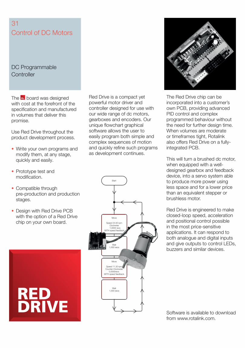
Red Drive is a compact yet powerful motor driver and controller designed for use with our wide range of dc motors, gearboxes and encoders. Our unique flowchart graphical software allows the user to easily program both simple and complex sequences of motion and quickly refine such programs as development continues.
The Red Drive chip can be incorporated into a customer’s own PCB, providing advanced PID control and complex programmed behaviour without the need for further design time. When volumes are moderate or timeframes tight, Rotalink also offers Red Drive on a fully-integrated PCB.
This will turn a brushed dc motor, when equipped with a well-designed gearbox and feedback device, into a servo system able to produce more power using less space and for a lower price than an equivalent stepper or brushless motor.
Red Drive is engineered to make closed-loop speed, acceleration and positional control possible in the most price-sensitive applications. It can respond to both analogue and digital inputs and give outputs to control LEDs, buzzers and similar devices.
Control of DC Motors
DC Programmable Controller
31
View our latest productsat www.rotalink.com
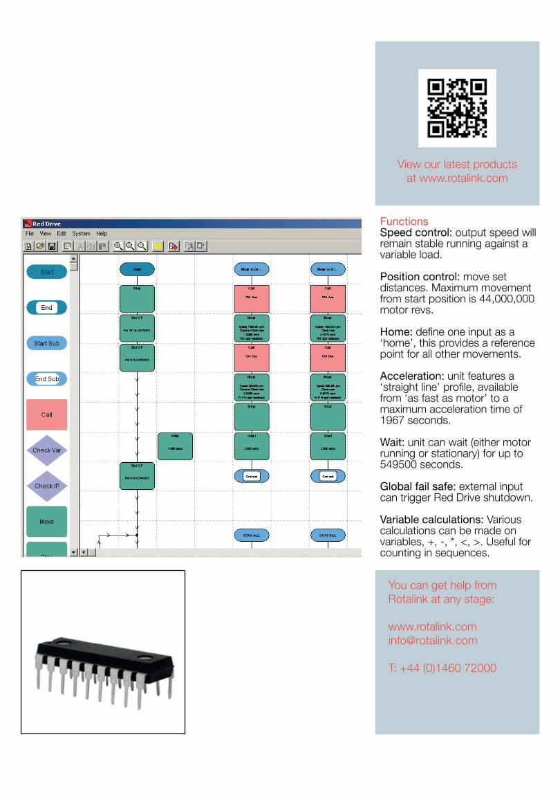
FunctionsSpeed control: output speed will remain stable running against a variable load.
Position control: move set distances. Maximum movement from start position is 44,000,000 motor revs.
Home: define one input as a ‘home’, this provides a reference point for all other movements.
Acceleration: unit features a ‘straight line’ profile, available from ‘as fast as motor’ to a maximum acceleration time of 1967 seconds.
Wait: unit can wait (either motor running or stationary) for up to 549500 seconds.
Global fail safe: external input can trigger Red Drive shutdown.
Variable calculations: Various calculations can be made on variables, +, -, *, <, >. Useful for counting in sequences.
You can get help from Rotalink at any stage:
T: +44 (0)1460 72000
33Control of DC Motors
Speed Controller
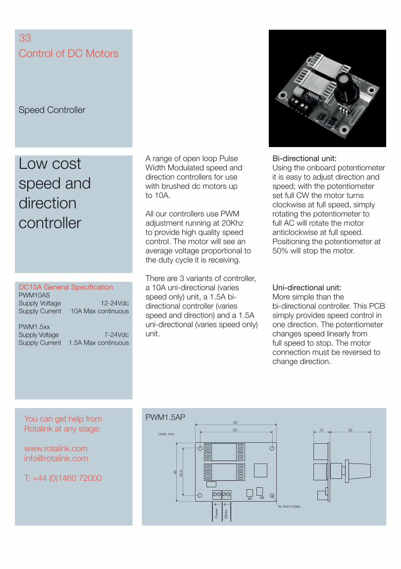
A range of open loop Pulse Width Modulated speed and direction controllers for use with brushed dc motors up to 10A.
All our controllers use PWM adjustment running at 20Khz to provide high quality speed control. The motor will see an average voltage proportional to the duty cycle it is receiving.
There are 3 variants of controller, a 10A uni-directional (varies speed only) unit, a 1.5A bi-directional controller (varies speed and direction) and a 1.5A uni-directional (varies speed only) unit.
Bi-directional unit:Using the onboard potentiometer it is easy to adjust direction and speed; with the potentiometer set full CW the motor turns clockwise at full speed, simply rotating the potentiometer to full AC will rotate the motor anticlockwise at full speed. Positioning the potentiometer at 50% will stop the motor.
Uni-directional unit:More simple than the bi-directional controller. This PCB simply provides speed control in one direction. The potentiometer changes speed linearly from full speed to stop. The motor connection must be reversed to change direction.
Low cost speed and direction controller
PWM1.5AP
Units: mm
35.5
4x 3mm holes
Pow
er
Mot
or
32
46
1255
63
+ - + -
DC10A General SpecificationPWM10AS Supply Voltage 12-24VdcSupply Current 10A Max continuous
PWM1.5xx Supply Voltage 7-24VdcSupply Current 1.5A Max continuous
You can get help from Rotalink at any stage:
T: +44 (0)1460 72000
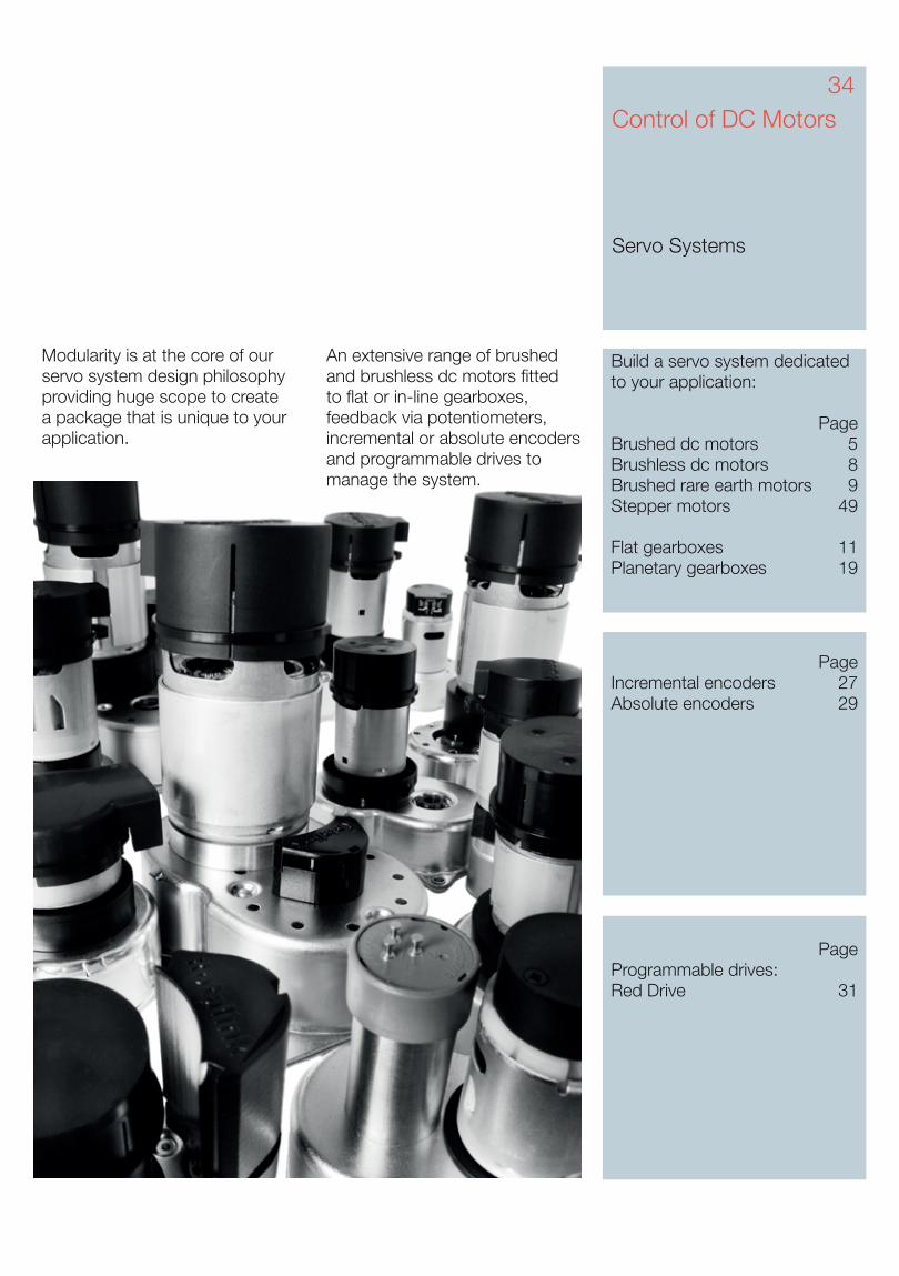
Modularity is at the core of our servo system design philosophy providing huge scope to create a package that is unique to your application.
Control of DC Motors
Servo Systems
Build a servo system dedicated to your application: PageBrushed dc motors 5Brushless dc motors 8Brushed rare earth motors 9Stepper motors 49
Flat gearboxes 11Planetary gearboxes 19
PageIncremental encoders 27Absolute encoders 29
PageProgrammable drives: Red Drive 31
An extensive range of brushed and brushless dc motors fitted to flat or in-line gearboxes, feedback via potentiometers, incremental or absolute encoders and programmable drives to manage the system.
34
AC Motors and Optional Gearboxes
Introduction
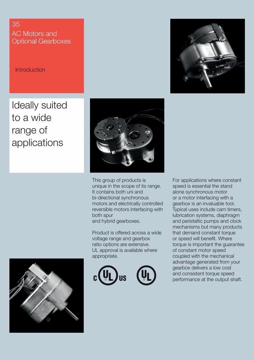
This group of products is unique in the scope of its range. It contains both uni and bi-directional synchronous motors and electrically controlled reversible motors interfacing with both spur and hybrid gearboxes.
Product is offered across a wide voltage range and gearbox ratio options are extensive. UL approval is available where appropriate.
For applications where constant speed is essential the stand alone synchronous motor or a motor interfacing with a gearbox is an invaluable tool. Typical uses include cam timers, lubrication systems, diaphragm and peristaltic pumps and clock mechanisms but many products that demand constant torque or speed will benefit. Where torque is important the guarantee of constant motor speed coupled with the mechanical advantage generated from your gearbox delivers a low cost and consistent torque speed performance at the output shaft.
Ideally suited to a wide range of applications
35
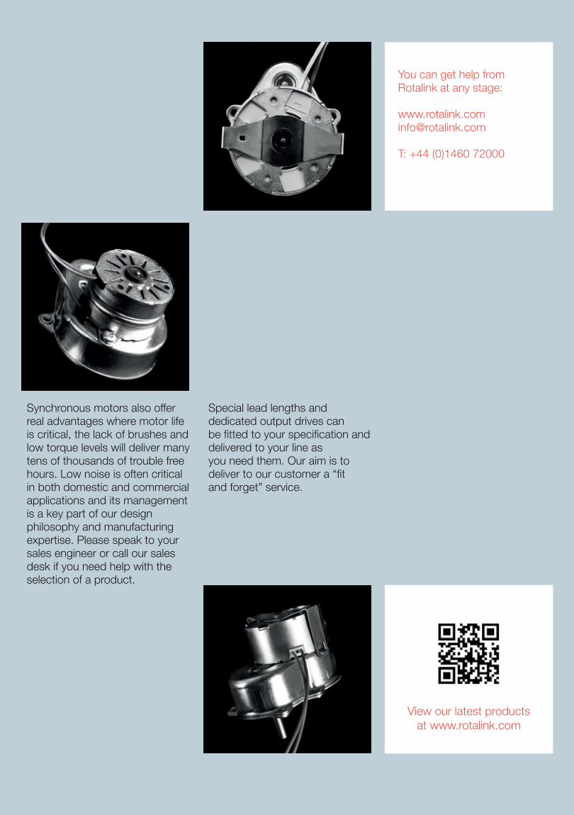
Special lead lengths and dedicated output drives can be fitted to your specification and delivered to your line as you need them. Our aim is to deliver to our customer a “fit and forget” service.
Synchronous motors also offer real advantages where motor life is critical, the lack of brushes and low torque levels will deliver many tens of thousands of trouble free hours. Low noise is often critical in both domestic and commercial applications and its management is a key part of our design philosophy and manufacturing expertise. Please speak to your sales engineer or call our sales desk if you need help with the selection of a product.
You can get help from Rotalink at any stage:
T: +44 (0)1460 72000
View our latest productsat www.rotalink.com
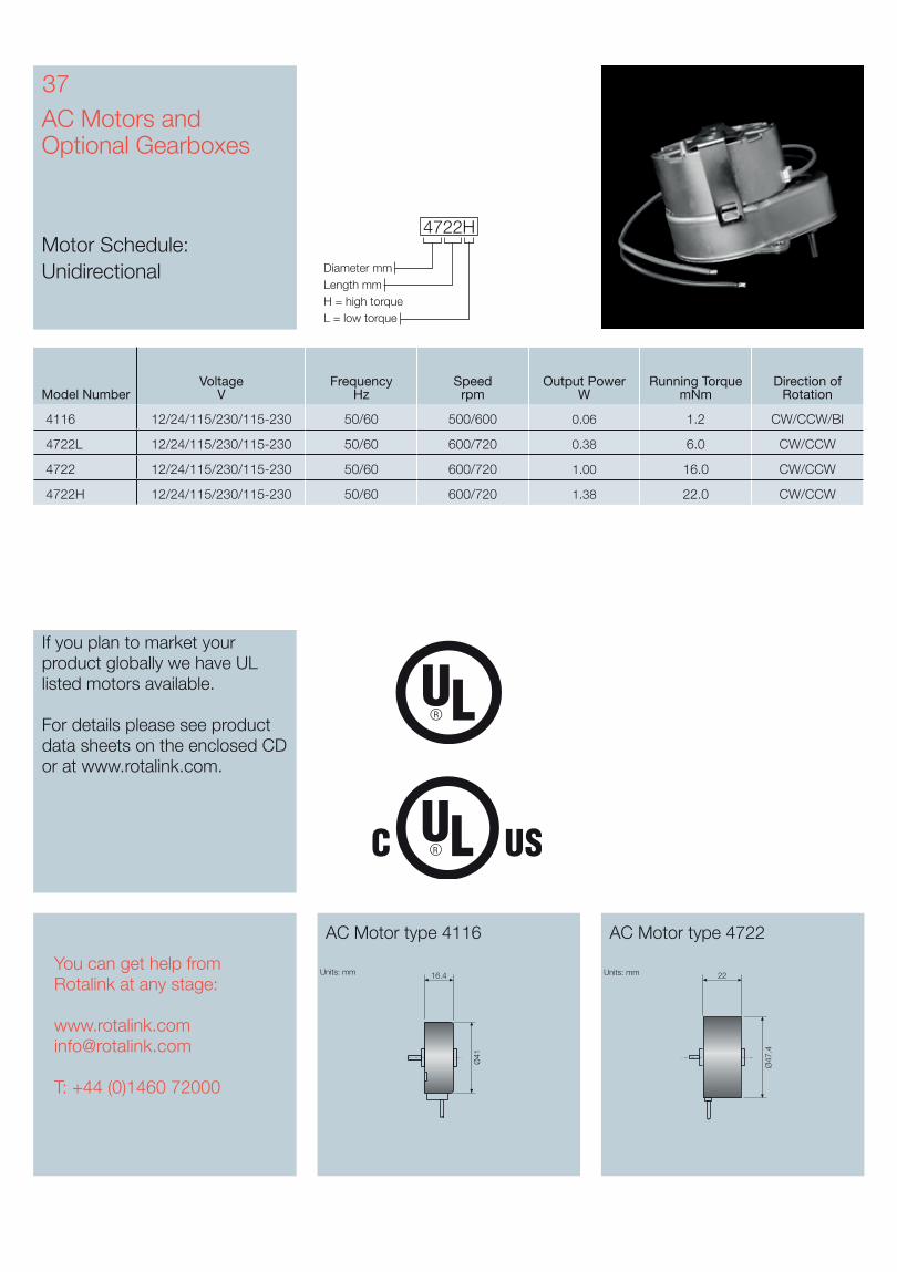
Diameter mm
4722H
Length mmH = high torqueL = low torque
AC Motors and Optional Gearboxes
Motor Schedule: Unidirectional
AC Motor type 4116 AC Motor type 4722
37
Units: mm Units: mm16.4
Ø41
22
Ø47
.4
If you plan to market your product globally we have UL listed motors available.
For details please see product data sheets on the enclosed CD or at www.rotalink.com.
You can get help from Rotalink at any stage:
T: +44 (0)1460 72000
Model NumberVoltage
VFrequency
HzSpeed
rpmOutput Power
WRunning Torque
mNmDirection of
Rotation
4116 12/24/115/230/115-230 50/60 500/600 0.06 1.2 CW/CCW/BI
4722L 12/24/115/230/115-230 50/60 600/720 0.38 6.0 CW/CCW
4722 12/24/115/230/115-230 50/60 600/720 1.00 16.0 CW/CCW
4722H 12/24/115/230/115-230 50/60 600/720 1.38 22.0 CW/CCW
Coil Ref.Mount
Body Length mm
Type codeBody diameter mm
Magnet
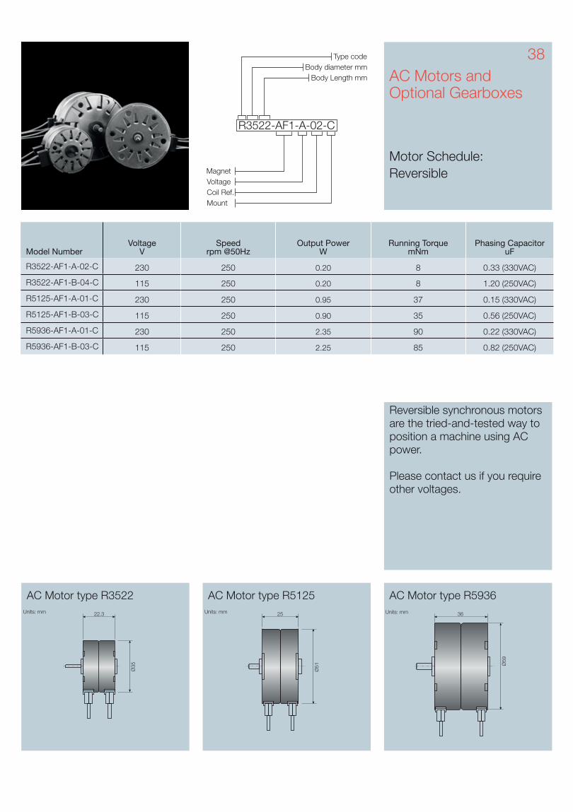
R3522-AF1-A-02-C
Voltage
AC Motors and Optional Gearboxes
Motor Schedule: Reversible
AC Motor type R3522 AC Motor type R5125 AC Motor type R5936
Ø35
Units: mm Units: mm22.3 25
Ø51
Units: mm 36
Ø59
Model NumberVoltage
VSpeed
rpm @50HzOutput Power
WRunning Torque
mNmPhasing Capacitor
uF
R3522-AF1-A-02-C 230 250 0.20 8 0.33 (330VAC)
R3522-AF1-B-04-C 115 250 0.20 8 1.20 (250VAC)
R5125-AF1-A-01-C 230 250 0.95 37 0.15 (330VAC)
R5125-AF1-B-03-C 115 250 0.90 35 0.56 (250VAC)
R5936-AF1-A-01-C 230 250 2.35 90 0.22 (330VAC)
R5936-AF1-B-03-C 115 250 2.25 85 0.82 (250VAC)
38
Reversible synchronous motors are the tried-and-tested way to position a machine using AC power.
Please contact us if you require other voltages.
39
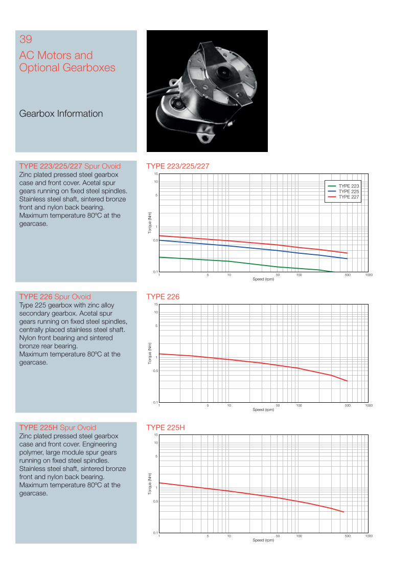
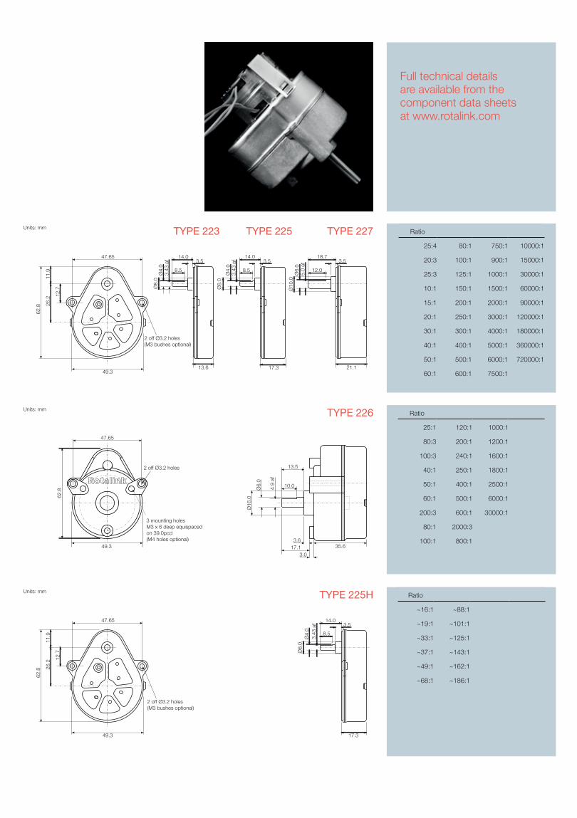
TYPE 223/225/227 TYPE 223/225/227 Spur OvoidZinc plated pressed steel gearbox case and front cover. Acetal spur gears running on fixed steel spindles. Stainless steel shaft, sintered bronze front and nylon back bearing.Maximum temperature 80ºC at the gearcase.
TYPE 226TYPE 226 Spur OvoidType 225 gearbox with zinc alloy secondary gearbox. Acetal spur gears running on fixed steel spindles, centrally placed stainless steel shaft. Nylon front bearing and sintered bronze rear bearing. Maximum temperature 80ºC at the gearcase.
TYPE 225HTYPE 225H Spur OvoidZinc plated pressed steel gearbox case and front cover. Engineering polymer, large module spur gears running on fixed steel spindles. Stainless steel shaft, sintered bronze front and nylon back bearing.Maximum temperature 80ºC at the gearcase.
AC Motors and Optional Gearboxes
Gearbox Information
Speed (rpm)
Torq
ue (N
m)
1 5 10 50 100 500 10000.1
0.5
1
5
10
15
TYPE 223TYPE 225TYPE 227
Speed (rpm)
Torq
ue (N
m)
1 5 10 50 100 500 10000.1
0.5
1
5
10
15
Speed (rpm)
Torq
ue (N
m)
1 5 10 50 100 500 10000.1
0.5
1
5
10
15
Ratio
25:4 80:1 750:1 10000:1
20:3 100:1 900:1 15000:1
25:3 125:1 1000:1 30000:1
10:1 150:1 1500:1 60000:1
15:1 200:1 2000:1 90000:1
20:1 250:1 3000:1 120000:1
30:1 300:1 4000:1 180000:1
40:1 400:1 5000:1 360000:1
50:1 500:1 6000:1 720000:1
60:1 600:1 7500:1
TYPE 225TYPE 223 TYPE 227
Ratio
25:1 120:1 1000:1
80:3 200:1 1200:1
100:3 240:1 1600:1
40:1 250:1 1800:1
50:1 400:1 2500:1
60:1 500:1 6000:1
200:3 600:1 30000:1
80:1 2000:3
100:1 800:1
TYPE 226
Ratio
~16:1 ~88:1
~19:1 ~101:1
~33:1 ~125:1
~37:1 ~143:1
~49:1 ~162:1
~68:1 ~186:1
TYPE 225H
Full technical details are available from the component data sheets at www.rotalink.com
Units: mm
47.65
62.8
49.3
2 off Ø3.2 holes
3 mounting holes M3 x 6 deep equispaced on 39.0pcd(M4 holes optional)
Ø16
.0
35.6
Ø6.
0
4.9
af
13.5
10.0
17.13.0
3.6
Units: mm
13.6
14.03.5
Ø4.
0Ø
8.0
3.43
af
8.5
17.3
14.03.5
Ø4.
03.
43 a
f
8.5
Ø8.
0
21.1
3.5
Ø6.
0Ø
10.0
5.0
af
18.7
12.0
49.3
2 off Ø3.2 holes(M3 bushes optional)
62.8
11.9
26.2
12.7
47.65
Units: mm
17.3
14.03.5
Ø8.
0Ø
4.0
3.43
af
8.5
49.3
2 off Ø3.2 holes(M3 bushes optional)
62.8
11.9
26.2
12.7
47.65
41
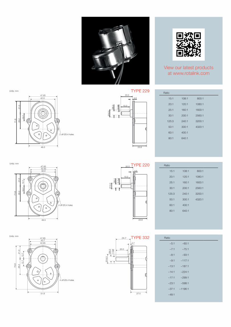
TYPE 332TYPE 332 Spur OvoidZinc plated pressed steel gearbox case and front cover with 4 point fixing. Spur gears running on fixed steel spindles. High performance polymer gears, stainless steel shaft, ball race front and back bearing. Maximum temperature 80ºC at the gearcase.
TYPE 220TYPE 220 Spur OvoidZinc plated pressed steel gearbox case and front cover with 4 point fixing. Spur gears running on fixed steel spindles. Engineering polymer gears, stainless steel shaft, sintered bronze front and nylon back bearing. Maximum temperature 80ºC at the gearcase.
AC Motors and Optional Gearboxes
Gearbox Information
Speed (rpm)
Torq
ue (N
m)
1 5 10 50 100 500 10000.1
0.5
1
5
10
15
Speed (rpm)
Torq
ue (N
m)
1 5 10 50 100 500 10000.1
0.5
1
5
10
15
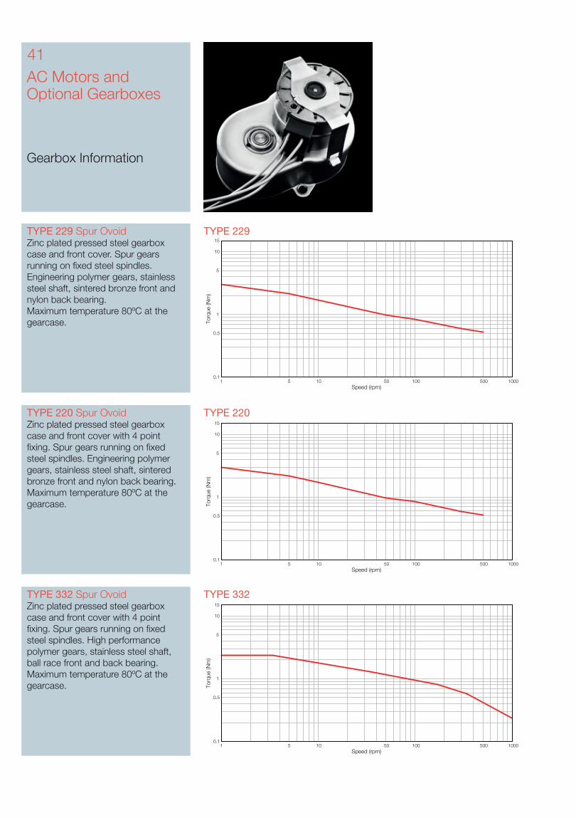
TYPE 229TYPE 229 Spur OvoidZinc plated pressed steel gearbox case and front cover. Spur gears running on fixed steel spindles. Engineering polymer gears, stainless steel shaft, sintered bronze front and nylon back bearing. Maximum temperature 80ºC at the gearcase.
Speed (rpm)
Torq
ue (N
m)
1 5 10 50 100 500 10000.1
0.5
1
5
10
15
Units: mm47.6543.742.65
51.8
21.3
12.7
12.7
26.2
73.9
27.5
24.7
2.7
20.0
Ø16
.0
Ø8.
07.
0af
4 off Ø3.4 holes
TYPE 332
Units: mm
49.3
4 off Ø3.4 holes
26.2 12
.7
47.65
42.0
71.8
21.0
42.65
12.7
23.8
3.5
Ø10
.0
5.5a
f
Ø6.
0
15.0
20.5 TYPE 220 Ratio
15:1 108:1 800:1
20:1 120:1 1080:1
25:1 160:1 1600:1
30:1 200:1 2560:1
125:3 240:1 3200:1
50:1 300:1 4320:1
60:1 400:1
80:1 640:1
View our latest productsat www.rotalink.com
Ratio
~5:1 ~60:1
~7:1 ~75:1
~8:1 ~93:1
~9:1 ~117:1
~13:1 ~187:1
~14:1 ~224:1
~17:1 ~299:1
~23:1 ~598:1
~37:1 ~1196:1
~48:1
Units: mm
49.3
2 off Ø3.4 holes
26.2 12
.7
47.6542.0
71.8
21.0
23.8
20.5
3.5
Ø10
.0
5.5a
f
Ø6.
0 15.0
TYPE 229 Ratio
15:1 108:1 800:1
20:1 120:1 1080:1
25:1 160:1 1600:1
30:1 200:1 2560:1
125:3 240:1 3200:1
50:1 300:1 4320:1
60:1 400:1
80:1 640:1
43AC Motors and Optional Gearboxes
Gearbox Information
TYPE 372TYPE 372 Spur OvoidZinc plated pressed steel gearbox case and front cover with 4 point fixing. Spur gears running on fixed steel spindles. High performance polymer gears, stainless steel shaft, ball race front and back bearing. Maximum temperature 80ºC at the gearcase.
Speed (rpm)
Torq
ue (N
m)
1 5 10 50 100 500 10000.1
0.5
1
5
10
15
TYPE 330 TYPE 330 HybridZinc plated pressed steel gearbox case and front cover with 4 point fixing. Spur gears running on fixed steel spindles leading to a planetary output stage. High performance polymer gears, stainless steel shaft, ball race front and back bearing. Maximum temperature 80ºC at the gearcase.
Speed (rpm)
Torq
ue (N
m)
1 5 10 50 100 500 10000.1
0.5
1
5
10
15
Full technical details are available from the component data sheets at www.rotalink.com
55.7451.2049.89
60.62
25.6
014
.89
14.8
930
.65
86.5
6
35.4
23.33.1
18.0Ø
19.0
Ø10
.0
9.0
af
Units: mm
4 off Ø4.4 holes
TYPE 372 Ratio
~5:1 ~75:1
~7:1 ~93:1
~8:1 ~117:1
~13:1 ~187:1
~17:1 ~224:1
~23:1 ~299:1
~37:1 ~1196:1
~60:1
Units: mm47.6543.742.65
51.8
21.3
12.7
12.7
26.2
73.9
27.5
24.7
2.7
20.0
Ø16
.0
Ø8.
07.
0af
4 off Ø3.4 holes
TYPE 330 Ratio
~16:1 ~205:1
~22:1 ~256:1
~29:1 ~320:1
~32:1 ~400:1
~43:1 ~639:1
~48:1 ~767:1
~58:1 ~1023:1
~80:1 ~2046:1
~128:1 ~4092:1
~164:1
45
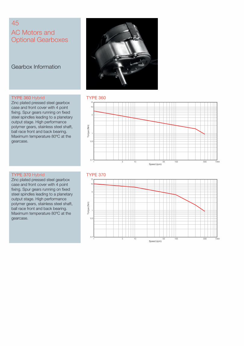
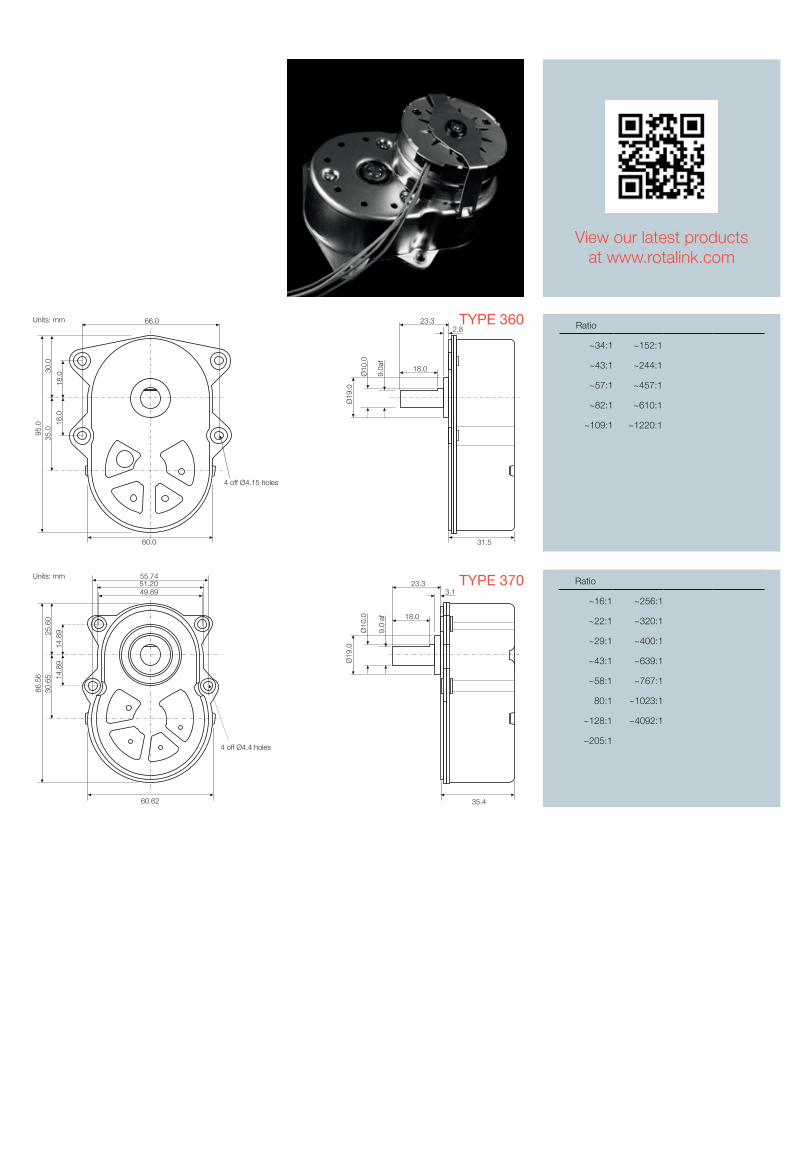
TYPE 370TYPE 370 HybridZinc plated pressed steel gearbox case and front cover with 4 point fixing. Spur gears running on fixed steel spindles leading to a planetary output stage. High performance polymer gears, stainless steel shaft, ball race front and back bearing. Maximum temperature 80ºC at the gearcase.
AC Motors and Optional Gearboxes
Gearbox Information
Speed (rpm)
Torq
ue (N
m)
1 5 10 50 100 500 10000.1
0.5
1
5
10
15
TYPE 360 HybridZinc plated pressed steel gearbox case and front cover with 4 point fixing. Spur gears running on fixed steel spindles leading to a planetary output stage. High performance polymer gears, stainless steel shaft, ball race front and back bearing. Maximum temperature 80ºC at the gearcase.
Speed (rpm)
Torq
ue (N
m)
1 5 10 50 100 500 10000.1
0.5
1
5
10
15
TYPE 360
30.0
4 off Ø4.15 holes
66.0
60.0
95.0 18
.018
.0
35.0
Units: mm2.8
23.3
18.0Ø
10.0
9.0a
f
Ø19
.0
31.5
TYPE 370 Ratio
~16:1 ~256:1
~22:1 ~320:1
~29:1 ~400:1
~43:1 ~639:1
~58:1 ~767:1
80:1 ~1023:1
~128:1 ~4092:1
~205:1
55.7451.2049.89
60.62
25.6
0
14.8
914
.89
30.6
586
.56
35.4
23.33.1
18.0
Ø19
.0
Ø10
.0
9.0
af
Units: mm
4 off Ø4.4 holes
TYPE 360 Ratio
~34:1 ~152:1
~43:1 ~244:1
~57:1 ~457:1
~82:1 ~610:1
~109:1 ~1220:1
View our latest productsat www.rotalink.com
Permanent Magnet and Hybrid Stepping Motors
Introduction
The widest range
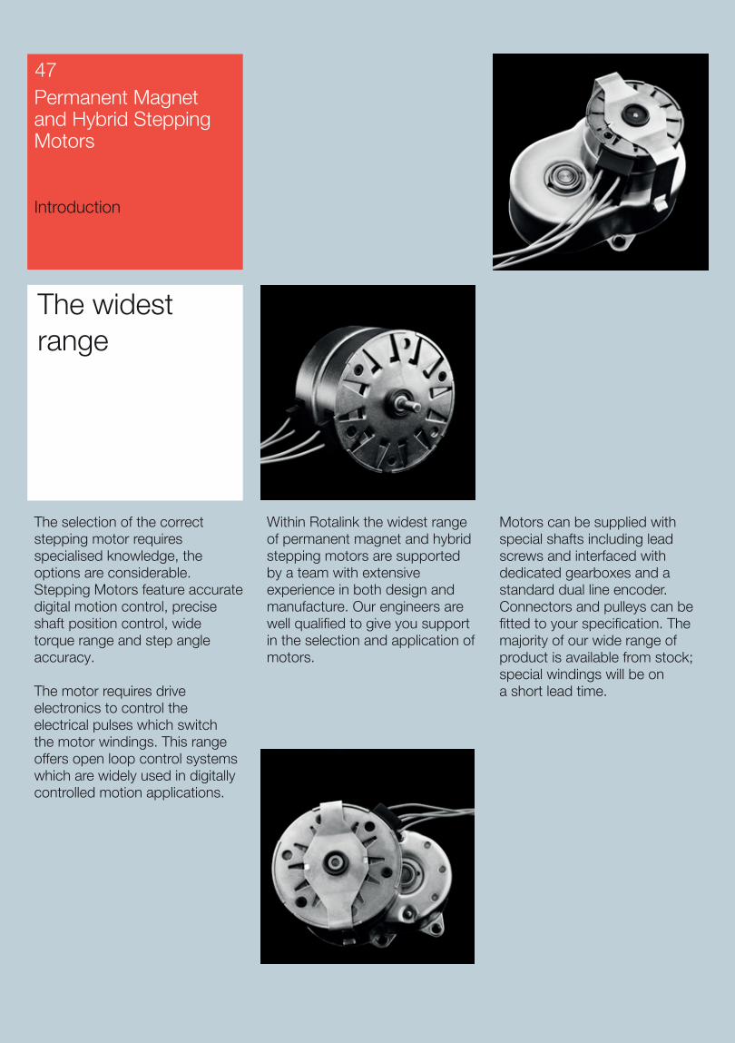
The selection of the correct stepping motor requires specialised knowledge, the options are considerable. Stepping Motors feature accurate digital motion control, precise shaft position control, wide torque range and step angle accuracy.
The motor requires drive electronics to control the electrical pulses which switch the motor windings. This range offers open loop control systems which are widely used in digitally controlled motion applications.
Motors can be supplied with special shafts including lead screws and interfaced with dedicated gearboxes and a standard dual line encoder. Connectors and pulleys can be fitted to your specification. The majority of our wide range of product is available from stock; special windings will be on a short lead time.
47
Within Rotalink the widest range of permanent magnet and hybrid stepping motors are supported by a team with extensive experience in both design and manufacture. Our engineers are well qualified to give you support in the selection and application of motors.
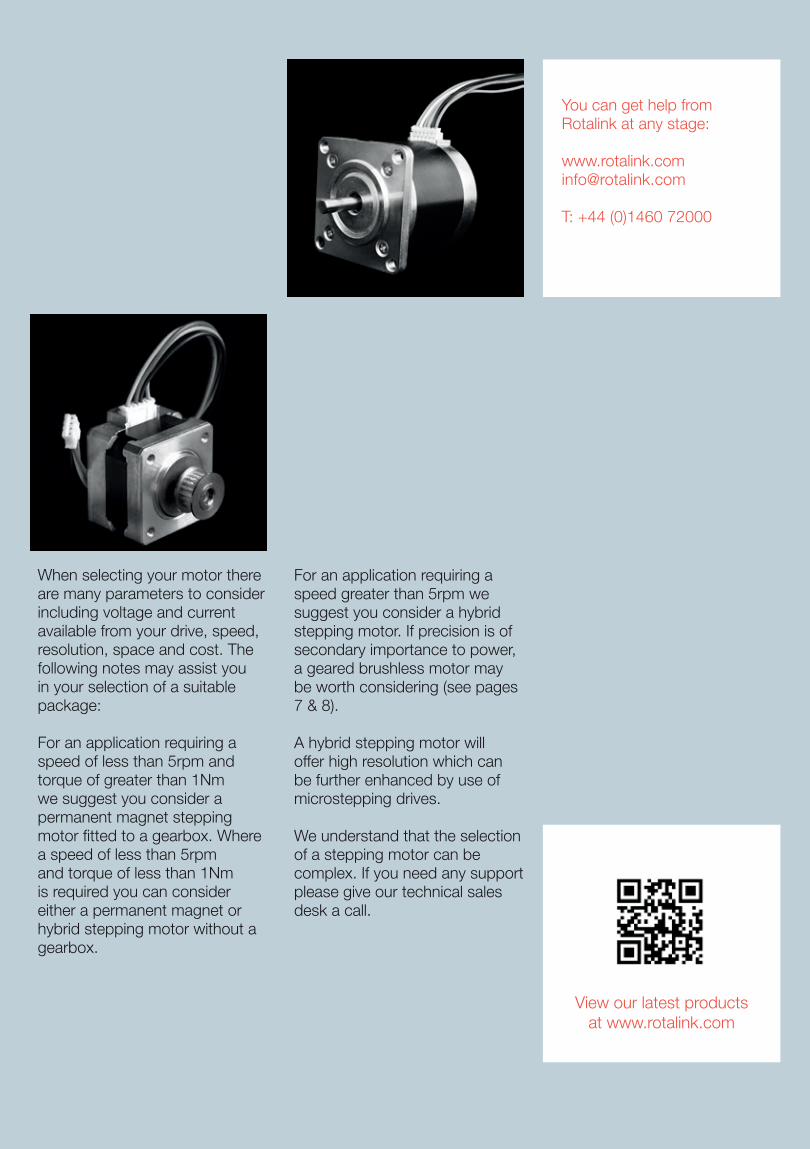
When selecting your motor there are many parameters to consider including voltage and current available from your drive, speed, resolution, space and cost. The following notes may assist you in your selection of a suitable package:
For an application requiring a speed of less than 5rpm and torque of greater than 1Nm we suggest you consider a permanent magnet stepping motor fitted to a gearbox. Where a speed of less than 5rpm and torque of less than 1Nm is required you can consider either a permanent magnet or hybrid stepping motor without a gearbox.
For an application requiring a speed greater than 5rpm we suggest you consider a hybrid stepping motor. If precision is of secondary importance to power, a geared brushless motor may be worth considering (see pages 7 & 8).
A hybrid stepping motor will offer high resolution which can be further enhanced by use of microstepping drives.
We understand that the selection of a stepping motor can be complex. If you need any support please give our technical sales desk a call.
You can get help from Rotalink at any stage:
T: +44 (0)1460 72000
View our latest productsat www.rotalink.com
Number of leads (4)Resistance
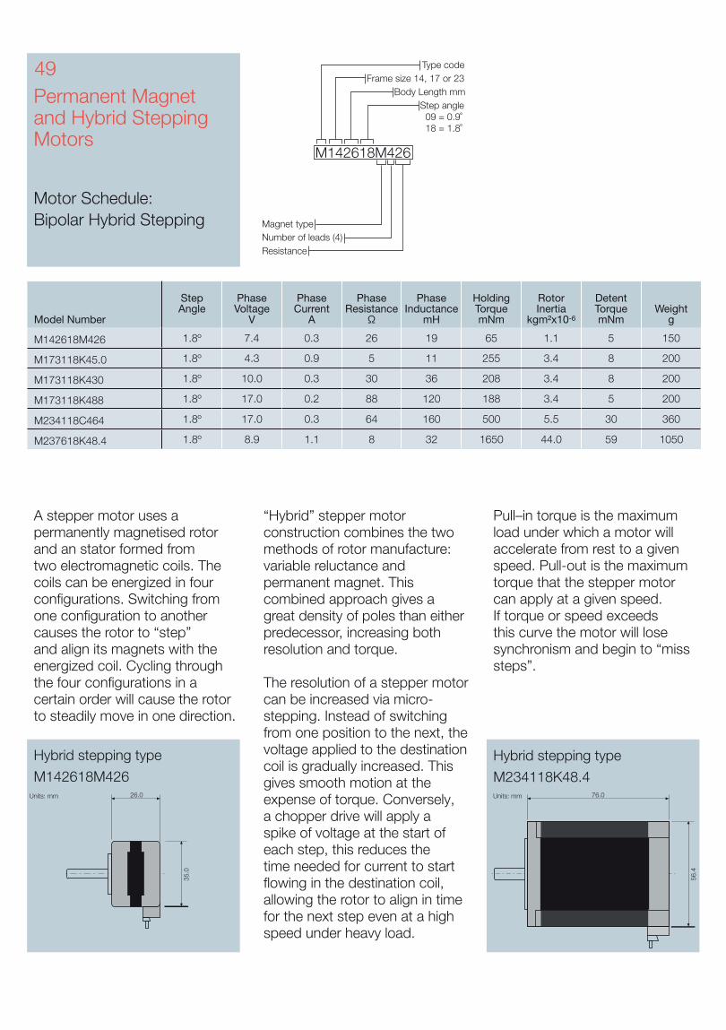
Body Length mm
Type code
Magnet type
Frame size 14, 17 or 23
Step angle 09 = 0.9˚ 18 = 1.8˚
M142618M426
Permanent Magnet and Hybrid Stepping Motors
Motor Schedule: Bipolar Hybrid Stepping
49
Model Number
Step Angle
Phase Voltage
V
Phase Current
A
Phase Resistance
Ω
Phase Inductance
mH
Holding Torque mNm
Rotor Inertia
kgm²x10-6
Detent Torque mNm
Weight g
M142618M426 1.8º 7.4 0.3 26 19 65 1.1 5 150
M173118K45.0 1.8º 4.3 0.9 5 11 255 3.4 8 200
M173118K430 1.8º 10.0 0.3 30 36 208 3.4 8 200
M173118K488 1.8º 17.0 0.2 88 120 188 3.4 5 200
M234118C464 1.8º 17.0 0.3 64 160 500 5.5 30 360
M237618K48.4 1.8º 8.9 1.1 8 32 1650 44.0 59 1050
Hybrid stepping type
M142618M426
Hybrid stepping type
M234118K48.4Units: mmUnits: mm
35.0
26.0
56.4
76.0
Pull–in torque is the maximum load under which a motor will accelerate from rest to a given speed. Pull-out is the maximum torque that the stepper motor can apply at a given speed. If torque or speed exceeds this curve the motor will lose synchronism and begin to “miss steps”.
A stepper motor uses a permanently magnetised rotor and an stator formed from two electromagnetic coils. The coils can be energized in four configurations. Switching from one configuration to another causes the rotor to “step” and align its magnets with the energized coil. Cycling through the four configurations in a certain order will cause the rotor to steadily move in one direction.
“Hybrid” stepper motor construction combines the two methods of rotor manufacture: variable reluctance and permanent magnet. This combined approach gives a great density of poles than either predecessor, increasing both resolution and torque.
The resolution of a stepper motor can be increased via micro-stepping. Instead of switching from one position to the next, the voltage applied to the destination coil is gradually increased. This gives smooth motion at the expense of torque. Conversely, a chopper drive will apply a spike of voltage at the start of each step, this reduces the time needed for current to start flowing in the destination coil, allowing the rotor to align in time for the next step even at a high speed under heavy load.
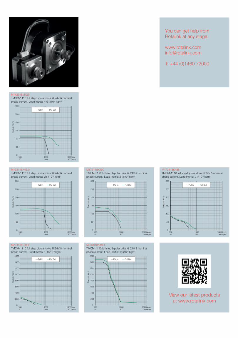
M142618M426TMCM-1110 full step bipolar drive @ 24V & nominal phase current. Load Inertia: 4.61x10⁻⁶ kgm2
M173118K45.0TMCM-1110 full step bipolar drive @ 24V & nominal phase current. Load Inertia: 21 x10-6 kgm2
M173118K488TMCM-1110 full step bipolar drive @ 24V & nominal phase current. Load Inertia: 21x10-6 kgm2
M173118K430TMCM-1110 full step bipolar drive @ 24V & nominal phase current. Load Inertia: 21x10-6 kgm2
M234118C464TMCM-1110 full step bipolar drive @ 24V & nominal phase current. Load Inertia: 109x10-6 kgm2
M237618K48.4TMCM-1110 full step bipolar drive @ 24V & nominal phase current. Load Inertia: 14x10-6 kgm2
You can get help from Rotalink at any stage:
T: +44 (0)1460 72000
0
200
400
600
800
1000
1200
1400
1600
Torq
ue (m
Nm
)
Pull In Pull Out
100 1000 10000pps 30 300 3000rpm
0
25
50
75
100
125
150
Torq
ue (m
Nm
)
Pull In Pull Out
100 1000 10000pps 30 300 3000rpm
0
50
100
150
200
250
300
Torq
ue (m
Nm
)
Pull In Pull Out
100 1000 10000pps 30 300 3000rpm
0
50
100
150
200
250
300
Torq
ue (m
Nm
)
Pull In Pull Out
100 1000 10000pps 30 300 3000rpm
0
50
100
150
200
250
300
Torq
ue (m
Nm
)
Pull In Pull Out
100 1000 10000pps 30 300 3000rpm
0
200
400
600
800
1000
1200
1400
1600
Torq
ue (m
Nm
)
Pull In Pull Out
100 1000 10000pps 30 300 3000rpm
View our latest productsat www.rotalink.com
Permanent Magnet and Hybrid Stepping Motors
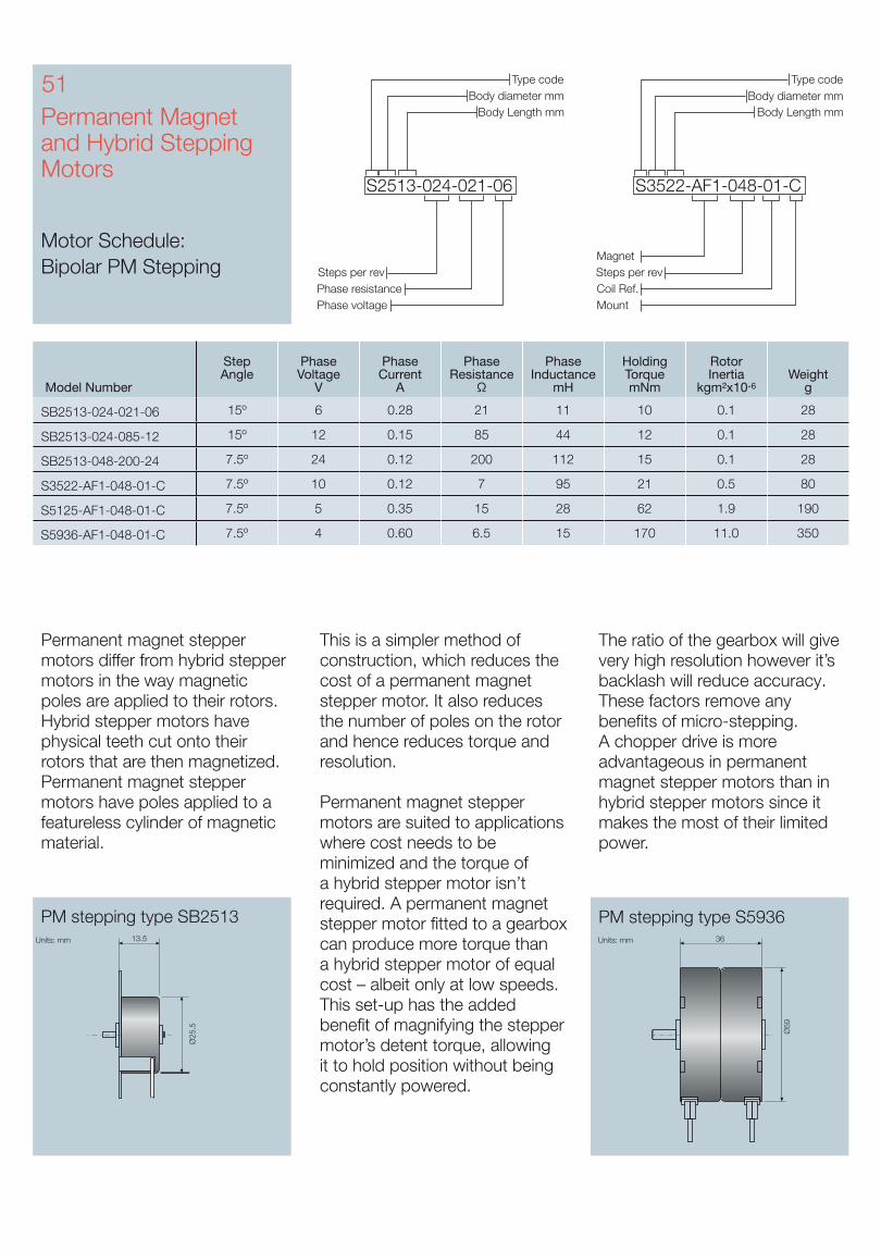
Motor Schedule: Bipolar PM Stepping
Permanent magnet stepper motors differ from hybrid stepper motors in the way magnetic poles are applied to their rotors. Hybrid stepper motors have physical teeth cut onto their rotors that are then magnetized. Permanent magnet stepper motors have poles applied to a featureless cylinder of magnetic material.
PM stepping type SB2513 PM stepping type S5936Units: mm13.5Units: mm
Ø25
.5
36
Ø59
51
Model Number
Step Angle
Phase Voltage
V
Phase Current
A
Phase Resistance
Ω
Phase Inductance
mH
Holding Torque mNm
Rotor Inertia
kgm²x10-6Weight
g
SB2513-024-021-06 15º 6 0.28 21 11 10 0.1 28
SB2513-024-085-12 15º 12 0.15 85 44 12 0.1 28
SB2513-048-200-24 7.5º 24 0.12 200 112 15 0.1 28
S3522-AF1-048-01-C 7.5º 10 0.12 7 95 21 0.5 80
S5125-AF1-048-01-C 7.5º 5 0.35 15 28 62 1.9 190
S5936-AF1-048-01-C 7.5º 4 0.60 6.5 15 170 11.0 350
This is a simpler method of construction, which reduces the cost of a permanent magnet stepper motor. It also reduces the number of poles on the rotor and hence reduces torque and resolution.
Permanent magnet stepper motors are suited to applications where cost needs to be minimized and the torque of a hybrid stepper motor isn’t required. A permanent magnet stepper motor fitted to a gearbox can produce more torque than a hybrid stepper motor of equal cost – albeit only at low speeds. This set-up has the added benefit of magnifying the stepper motor’s detent torque, allowing it to hold position without being constantly powered.
The ratio of the gearbox will give very high resolution however it’s backlash will reduce accuracy. These factors remove any benefits of micro-stepping. A chopper drive is more advantageous in permanent magnet stepper motors than in hybrid stepper motors since it makes the most of their limited power.
Coil Ref.Mount
Body Length mm
Type codeBody diameter mm
Steps per rev
S3522-AF1-048-01-C
Magnet
Phase resistancePhase voltage
Body Length mm
Type codeBody diameter mm
Steps per rev
S2513-024-021-06
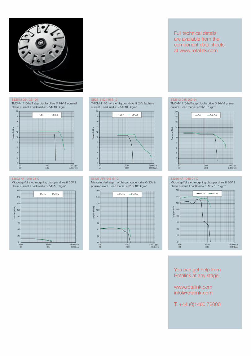
SB2513-024-021-06TMCM-1110 half step bipolar drive @ 24V & nominal phase current. Load Inertia: 9.54x10⁻⁷ kgm2
SB2513-024-085-12TMCM-1110 half step bipolar drive @ 24V & phase current. Load Inertia: 9.54x10⁻⁷ kgm2
SB2513-048-200-24TMCM-1110 half step bipolar drive @ 24V & phase current. Load Inertia: 4.29x10⁻⁷ kgm2
Full technical details are available from the component data sheets at www.rotalink.com
S3522-AF1-048-01-CMicrostep/full step morphing chopper drive @ 30V & phase current. Load Inertia: 9.54×10⁻⁷ kgm2
S5125-AF1-048-01-CMicrostep/full step morphing chopper drive @ 30V & phase current. Load Inertia: 4.61 x 10⁻⁶ kgm2
S5936-AF1-048-01-CMicrostep/full step morphing chopper drive @ 30V & phase current. Load Inertia: 2.10 x 10⁻⁵ kgm2
You can get help from Rotalink at any stage:
T: +44 (0)1460 72000
0
20
40
60
80
100
120
140
160
Torq
ue (m
Nm
)
Pull In Pull Out
480 4800 48000pps 60 600 6000rpm
0
20
40
60
80
100
120
140
160
Torq
ue (m
Nm
)
Pull In Pull Out
480 4800 48000pps 60 600 6000rpm
0
20
40
60
80
100
120
140
160
Torq
ue (m
Nm
)
Pull In Pull Out
480 4800 48000pps 60 600 6000rpm
0
2
4
6
8
10
12
14
16
18
20
Torq
ue (m
Nm
)
Pull In Pull Out
20 200 2000pps50 500 5000rpm
0
2
4
6
8
10
12
14
16
18
20
Torq
ue (m
Nm
)
Pull In Pull Out
20 200 2000pps50 500 5000rpm
0
2
4
6
8
10
12
14
16
18
20
Torq
ue (m
Nm
)
Pull In Pull Out
20 200 2000pps50 500 5000rpm
Permanent Magnet and Hybrid Stepping Motors
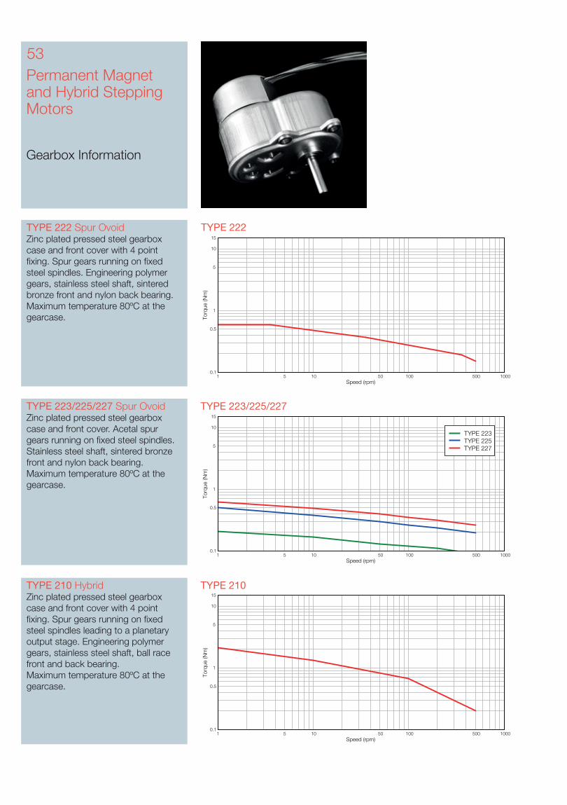
Gearbox Information
53
TYPE 223/225/227 TYPE 223/225/227 Spur OvoidZinc plated pressed steel gearbox case and front cover. Acetal spur gears running on fixed steel spindles. Stainless steel shaft, sintered bronze front and nylon back bearing.Maximum temperature 80ºC at the gearcase.
TYPE 222TYPE 222 Spur OvoidZinc plated pressed steel gearbox case and front cover with 4 point fixing. Spur gears running on fixed steel spindles. Engineering polymer gears, stainless steel shaft, sintered bronze front and nylon back bearing. Maximum temperature 80ºC at the gearcase.
TYPE 210 TYPE 210 HybridZinc plated pressed steel gearbox case and front cover with 4 point fixing. Spur gears running on fixed steel spindles leading to a planetary output stage. Engineering polymer gears, stainless steel shaft, ball race front and back bearing. Maximum temperature 80ºC at the gearcase.
Speed (rpm)
Torq
ue (N
m)
1 5 10 50 100 500 10000.1
0.5
1
5
10
15
Speed (rpm)
Torq
ue (N
m)
1 5 10 50 100 500 10000.1
0.5
1
5
10
15
TYPE 223TYPE 225TYPE 227
Speed (rpm)
Torq
ue (N
m)
1 5 10 50 100 500 10000.1
0.5
1
5
10
15
Units: mm
8.0
27.0
31.0
10.0
28.6
14.3
16.0
44.6
4 off Ø2.6 holes
2.6
Ø12
.0
5.5a
f
Ø6.
0
20.0
12.0
17.7
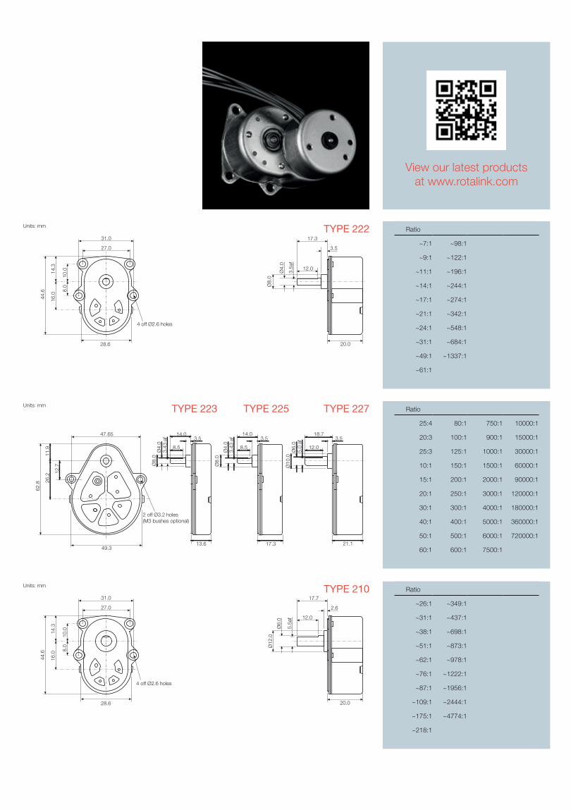
Ratio
25:4 80:1 750:1 10000:1
20:3 100:1 900:1 15000:1
25:3 125:1 1000:1 30000:1
10:1 150:1 1500:1 60000:1
15:1 200:1 2000:1 90000:1
20:1 250:1 3000:1 120000:1
30:1 300:1 4000:1 180000:1
40:1 400:1 5000:1 360000:1
50:1 500:1 6000:1 720000:1
60:1 600:1 7500:1
TYPE 225TYPE 223 TYPE 227
Units: mm
8.0
27.0
31.0
10.0
28.6
14.3
16.0
44.6
4 off Ø2.6 holes
3.5
20.0
Ø8.
0
3.5a
f
Ø4.
0
12.0
17.3
TYPE 222
TYPE 210
View our latest productsat www.rotalink.com
Ratio
~7:1 ~98:1
~9:1 ~122:1
~11:1 ~196:1
~14:1 ~244:1
~17:1 ~274:1
~21:1 ~342:1
~24:1 ~548:1
~31:1 ~684:1
~49:1 ~1337:1
~61:1
Ratio
~26:1 ~349:1
~31:1 ~437:1
~38:1 ~698:1
~51:1 ~873:1
~62:1 ~978:1
~76:1 ~1222:1
~87:1 ~1956:1
~109:1 ~2444:1
~175:1 ~4774:1
~218:1
Units: mm
13.6
14.03.5
Ø4.
0Ø
8.0
3.43
af
8.5
17.3
14.03.5
Ø4.
03.
43 a
f
8.5
Ø8.
0
21.1
3.5
Ø6.
0Ø
10.0
5.0
af
18.7
12.0
49.3
2 off Ø3.2 holes(M3 bushes optional)
62.8
11.9
26.2
12.7
47.65
Permanent Magnet and Hybrid Stepping Motors
Gearbox Information
55
TYPE 226TYPE 226 Spur OvoidType 225 gearbox with zinc alloy secondary gearbox. Acetal spur gears running on fixed steel spindles, centrally placed stainless steel shaft. Nylon front bearing and sintered bronze rear bearing. Maximum temperature 80ºC at the gearcase.
TYPE 225HTYPE 225H Spur OvoidZinc plated pressed steel gearbox case and front cover. Engineering polymer, large module spur gears running on fixed steel spindles. Stainless steel shaft, sintered bronze front and nylon back bearing.Maximum temperature 80ºC at the gearcase.
Speed (rpm)
Torq
ue (N
m)
1 5 10 50 100 500 10000.1
0.5
1
5
10
15
Speed (rpm)
Torq
ue (N
m)
1 5 10 50 100 500 10000.1
0.5
1
5
10
15
TYPE 229TYPE 229 Spur OvoidZinc plated pressed steel gearbox case and front cover. Spur gears running on fixed steel spindles. Engineering polymer gears, stainless steel shaft, sintered bronze front and nylon back bearing. Maximum temperature 80ºC at the gearcase.
Speed (rpm)
Torq
ue (N
m)
1 5 10 50 100 500 10000.1
0.5
1
5
10
15
Units: mm
47.65
62.8
49.3
2 off Ø3.2 holes
3 mounting holes M3 x 6 deep equispaced on 39.0pcd(M4 holes optional)
Ø16
.0
35.6
Ø6.
0
4.9
af
13.5
10.0
17.13.0
3.6
Ratio
25:1 120:1 1000:1
80:3 200:1 1200:1
100:3 240:1 1600:1
40:1 250:1 1800:1
50:1 400:1 2500:1
60:1 500:1 6000:1
200:3 600:1 30000:1
80:1 2000:3
100:1 800:1
TYPE 226
Ratio
~16:1 ~88:1
~19:1 ~101:1
~33:1 ~125:1
~37:1 ~143:1
~49:1 ~162:1
~68:1 ~186:1
TYPE 225H
Full technical details are available from the component data sheets at www.rotalink.com
Units: mm
49.3
2 off Ø3.4 holes
26.2 12
.7
47.6542.0
71.8
21.0
23.8
20.5
3.5
Ø10
.0
5.5a
f
Ø6.
0 15.0
TYPE 229 Ratio
15:1 108:1 800:1
20:1 120:1 1080:1
25:1 160:1 1600:1
30:1 200:1 2560:1
125:3 240:1 3200:1
50:1 300:1 4320:1
60:1 400:1
80:1 640:1
Units: mm
17.3
14.03.5
Ø8.
0Ø
4.0
3.43
af
8.5
49.3
2 off Ø3.2 holes(M3 bushes optional)
62.8
11.9
26.2
12.7
47.65
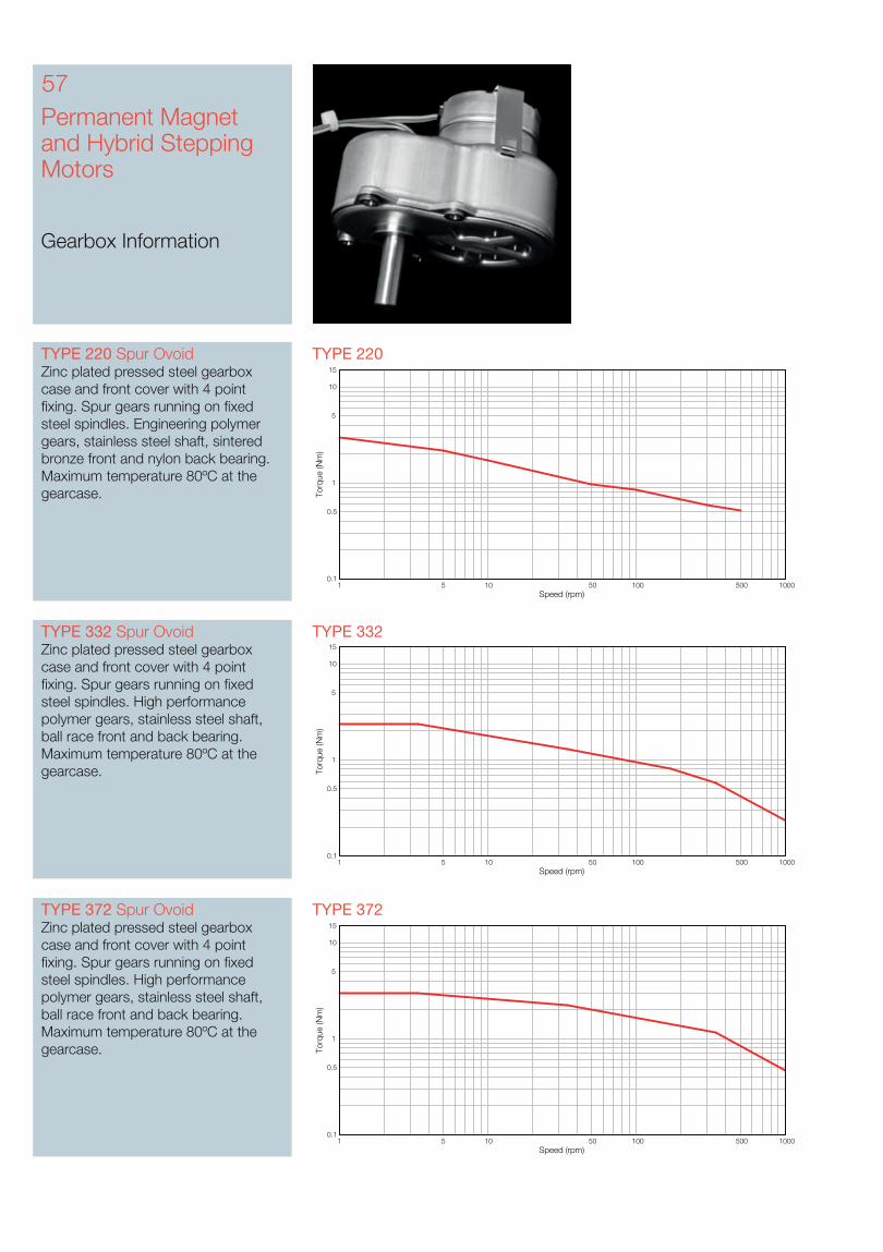
Permanent Magnet and Hybrid Stepping Motors
Gearbox Information
57
TYPE 372TYPE 372 Spur OvoidZinc plated pressed steel gearbox case and front cover with 4 point fixing. Spur gears running on fixed steel spindles. High performance polymer gears, stainless steel shaft, ball race front and back bearing. Maximum temperature 80ºC at the gearcase.
Speed (rpm)
Torq
ue (N
m)
1 5 10 50 100 500 10000.1
0.5
1
5
10
15
TYPE 332TYPE 332 Spur OvoidZinc plated pressed steel gearbox case and front cover with 4 point fixing. Spur gears running on fixed steel spindles. High performance polymer gears, stainless steel shaft, ball race front and back bearing. Maximum temperature 80ºC at the gearcase.
Speed (rpm)
Torq
ue (N
m)
1 5 10 50 100 500 10000.1
0.5
1
5
10
15
TYPE 220TYPE 220 Spur OvoidZinc plated pressed steel gearbox case and front cover with 4 point fixing. Spur gears running on fixed steel spindles. Engineering polymer gears, stainless steel shaft, sintered bronze front and nylon back bearing. Maximum temperature 80ºC at the gearcase.
Speed (rpm)
Torq
ue (N
m)
1 5 10 50 100 500 10000.1
0.5
1
5
10
15
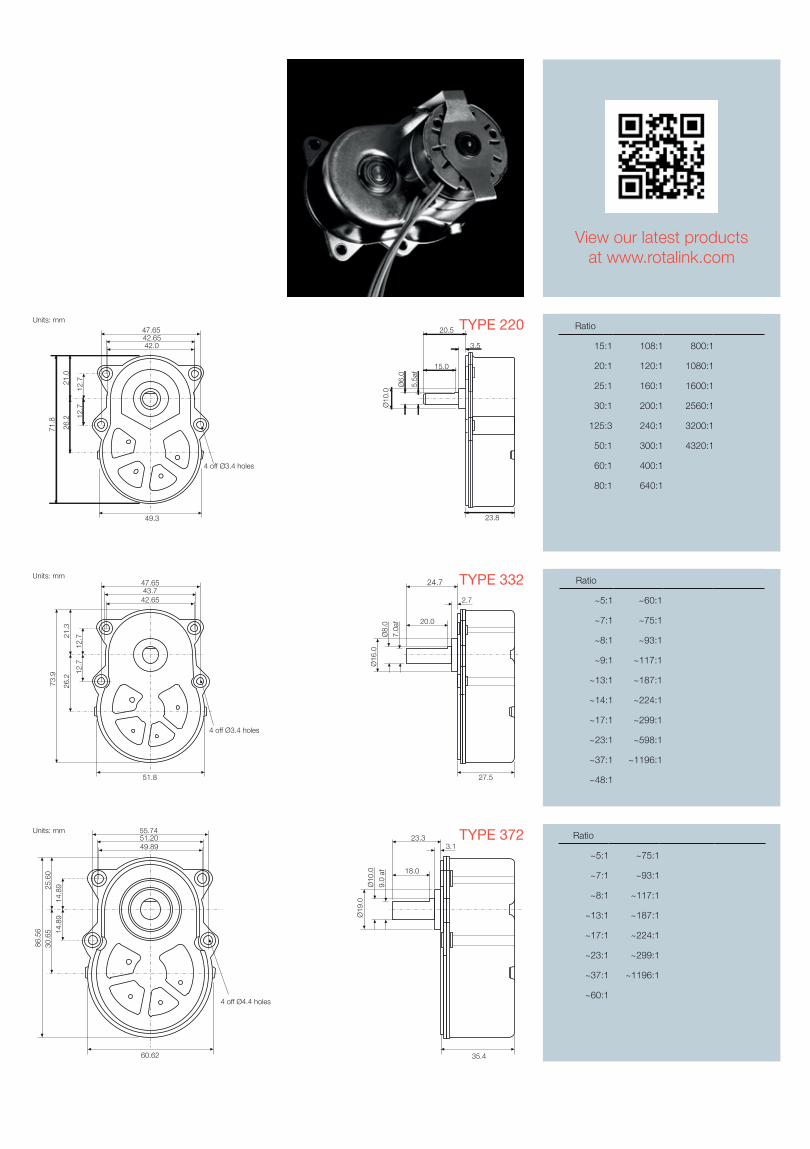
55.7451.2049.89
60.62
25.6
014
.89
14.8
930
.65
86.5
6
35.4
23.33.1
18.0
Ø19
.0Ø
10.0
9.0
af
Units: mm
4 off Ø4.4 holes
TYPE 372 Ratio
~5:1 ~75:1
~7:1 ~93:1
~8:1 ~117:1
~13:1 ~187:1
~17:1 ~224:1
~23:1 ~299:1
~37:1 ~1196:1
~60:1
View our latest productsat www.rotalink.com
Units: mm47.6543.742.65
51.8
21.3
12.7
12.7
26.2
73.9
27.5
24.7
2.7
20.0
Ø16
.0
Ø8.
07.
0af
4 off Ø3.4 holes
TYPE 332 Ratio
~5:1 ~60:1
~7:1 ~75:1
~8:1 ~93:1
~9:1 ~117:1
~13:1 ~187:1
~14:1 ~224:1
~17:1 ~299:1
~23:1 ~598:1
~37:1 ~1196:1
~48:1
Units: mm
49.3
4 off Ø3.4 holes
26.2 12
.7
47.65
42.0
71.8
21.0
42.65
12.7
23.8
3.5
Ø10
.0
5.5a
f
Ø6.
0
15.0
20.5 TYPE 220 Ratio
15:1 108:1 800:1
20:1 120:1 1080:1
25:1 160:1 1600:1
30:1 200:1 2560:1
125:3 240:1 3200:1
50:1 300:1 4320:1
60:1 400:1
80:1 640:1
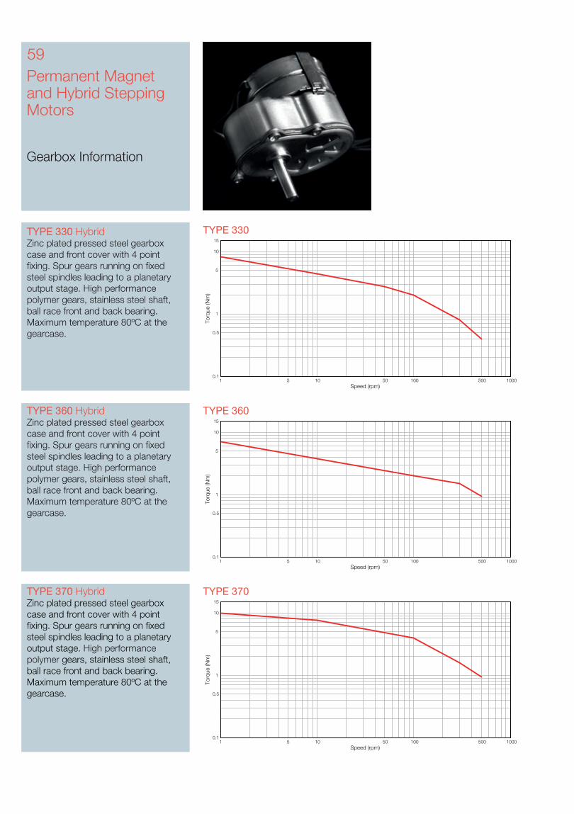
Permanent Magnet and Hybrid Stepping Motors
Gearbox Information
59
TYPE 330 TYPE 330 HybridZinc plated pressed steel gearbox case and front cover with 4 point fixing. Spur gears running on fixed steel spindles leading to a planetary output stage. High performance polymer gears, stainless steel shaft, ball race front and back bearing. Maximum temperature 80ºC at the gearcase.
TYPE 370TYPE 370 HybridZinc plated pressed steel gearbox case and front cover with 4 point fixing. Spur gears running on fixed steel spindles leading to a planetary output stage. High performance polymer gears, stainless steel shaft, ball race front and back bearing. Maximum temperature 80ºC at the gearcase.
Speed (rpm)
Torq
ue (N
m)
1 5 10 50 100 500 10000.1
0.5
1
5
10
15
Speed (rpm)
Torq
ue (N
m)
1 5 10 50 100 500 10000.1
0.5
1
5
10
15
TYPE 360 HybridZinc plated pressed steel gearbox case and front cover with 4 point fixing. Spur gears running on fixed steel spindles leading to a planetary output stage. High performance polymer gears, stainless steel shaft, ball race front and back bearing. Maximum temperature 80ºC at the gearcase.
Speed (rpm)
Torq
ue (N
m)
1 5 10 50 100 500 10000.1
0.5
1
5
10
15
TYPE 360
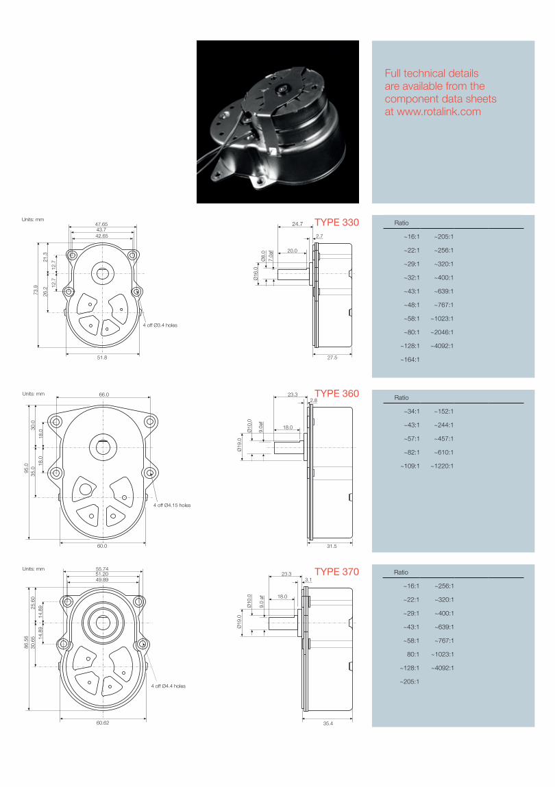
Units: mm47.6543.742.65
51.8
21.3
12.7
12.7
26.2
73.9
27.5
24.7
2.7
20.0Ø
16.0
Ø8.
07.
0af
4 off Ø3.4 holes
TYPE 330
TYPE 370 Ratio
~16:1 ~256:1
~22:1 ~320:1
~29:1 ~400:1
~43:1 ~639:1
~58:1 ~767:1
80:1 ~1023:1
~128:1 ~4092:1
~205:1
55.7451.2049.89
60.62
25.6
0
14.8
914
.89
30.6
586
.56
35.4
23.33.1
18.0
Ø19
.0
Ø10
.0
9.0
af
Units: mm
4 off Ø4.4 holes
Full technical details are available from the component data sheets at www.rotalink.com
Ratio
~16:1 ~205:1
~22:1 ~256:1
~29:1 ~320:1
~32:1 ~400:1
~43:1 ~639:1
~48:1 ~767:1
~58:1 ~1023:1
~80:1 ~2046:1
~128:1 ~4092:1
~164:1
TYPE 360 Ratio
~34:1 ~152:1
~43:1 ~244:1
~57:1 ~457:1
~82:1 ~610:1
~109:1 ~1220:1
30.0
4 off Ø4.15 holes
66.0
60.0
95.0 18
.018
.0
35.0
Units: mm2.8
23.3
18.0
Ø10
.0
9.0a
f
Ø19
.0
31.5
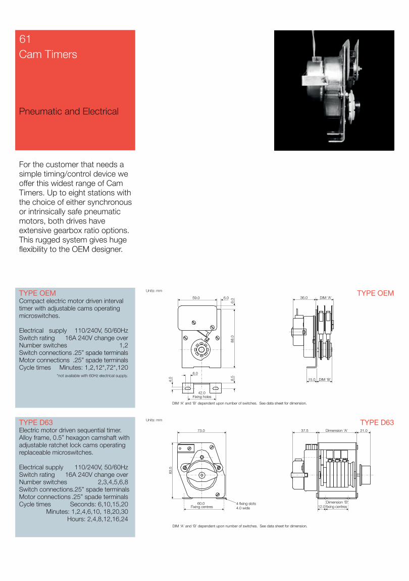
Cam Timers
Pneumatic and Electrical
For the customer that needs a simple timing/control device we offer this widest range of Cam Timers. Up to eight stations with the choice of either synchronous or intrinsically safe pneumatic motors, both drives have extensive gearbox ratio options. This rugged system gives huge flexibility to the OEM designer.
TYPE OEMCompact electric motor driven interval timer with adjustable cams operating microswitches.
Electrical supply 110/240V, 50/60HzSwitch rating 16A 240V change overNumber switches 1,2Switch connections .25” spade terminalsMotor connections .25” spade terminalsCycle times Minutes: 1,2,12*,72*,120 *not available with 60Hz electrical supply.
TYPE D63Electric motor driven sequential timer. Alloy frame, 0.5” hexagon camshaft with adjustable ratchet lock cams operating replaceable microswitches.
Electrical supply 110/240V, 50/60HzSwitch rating 16A 240V change overNumber switches 2,3,4,5,6,8Switch connections .25” spade terminalsMotor connections .25” spade terminalsCycle times Seconds: 6,10,15,20 Minutes: 1,2,4,6,10, 18,20,30 Hours: 2,4,8,12,16,24
TYPE OEM
TYPE D63
61
Units: mm
DIM ‘A’ and ‘B’ dependent upon number of switches. See data sheet for dimension.
DIM 'B'
DIM 'A'36.0
15.0
59.0 6.0
42.0Fixing holes
4.0
88.0
8.5
6.0
6.0
Units: mm
60.0Fixing centres
4 fixing slots4.0 wide
73.0
DIM ‘A’ and ‘B’ dependent upon number of switches. See data sheet for dimension.
83.5
12.0Dimension 'B'fixing centres
21.0Dimension 'A'37.5
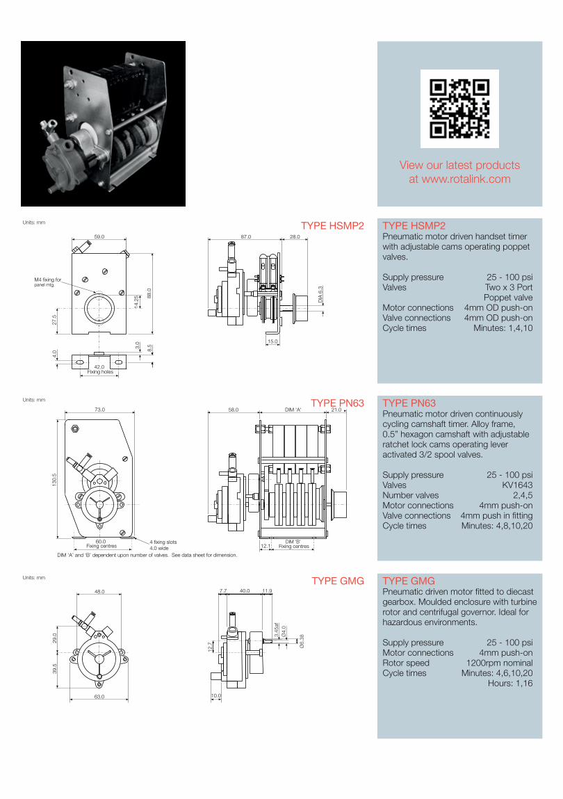
TYPE HSMP2Pneumatic motor driven handset timer with adjustable cams operating poppet valves.
Supply pressure 25 - 100 psiValves Two x 3 Port Poppet valveMotor connections 4mm OD push-on Valve connections 4mm OD push-on Cycle times Minutes: 1,4,10
TYPE PN63Pneumatic motor driven continuously cycling camshaft timer. Alloy frame, 0.5” hexagon camshaft with adjustable ratchet lock cams operating lever activated 3/2 spool valves.
Supply pressure 25 - 100 psiValves KV1643 Number valves 2,4,5Motor connections 4mm push-on Valve connections 4mm push in fitting Cycle times Minutes: 4,8,10,20
TYPE GMGPneumatic driven motor fitted to diecast gearbox. Moulded enclosure with turbine rotor and centrifugal governor. Ideal for hazardous environments.
Supply pressure 25 - 100 psiMotor connections 4mm push-onRotor speed 1200rpm nominalCycle times Minutes: 4,6,10,20 Hours: 1,16
TYPE HSMP2
TYPE PN63
TYPE GMG
View our latest productsat www.rotalink.com
Units: mm
DIM ‘A’ and ‘B’ dependent upon number of valves. See data sheet for dimension.
60.0Fixing centres
4 fixing slots4.0 wide
73.0
130.
5
12.1DIM 'B'
Fixing centres
21.0DIM 'A'58.0
Units: mm
59.0
42.0Fixing holes
27.5
4.0
14.2
5 88.0
8.53.0
M4 fixing forpanel mtg.
15.0
28.087.0
DIA
6.3
Units: mm
63.0
48.0
29.0
39.5
40.07.7
10.0
11.9
Ø6.
38
Ø4.
03.
45af
12.7
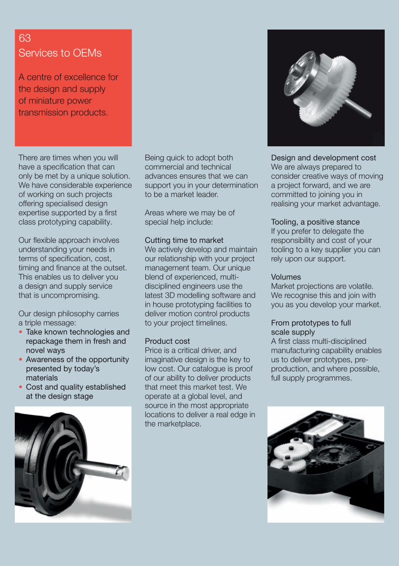
There are times when you will have a specification that can only be met by a unique solution. We have considerable experience of working on such projects offering specialised design expertise supported by a first class prototyping capability.
Our flexible approach involves understanding your needs in terms of specification, cost, timing and finance at the outset. This enables us to deliver you a design and supply service that is uncompromising.
Our design philosophy carries a triple message:• Take known technologies and
repackage them in fresh and novel ways• Awareness of the opportunity
presented by today’s materials
• Cost and quality established at the design stage
Being quick to adopt both commercial and technical advances ensures that we can support you in your determination to be a market leader.
Areas where we may be of special help include:
Cutting time to marketWe actively develop and maintain our relationship with your project management team. Our unique blend of experienced, multi-disciplined engineers use the latest 3D modelling software and in house prototyping facilities to deliver motion control products to your project timelines.
Product costPrice is a critical driver, and imaginative design is the key to low cost. Our catalogue is proof of our ability to deliver products that meet this market test. We operate at a global level, and source in the most appropriate locations to deliver a real edge in the marketplace.
Design and development costWe are always prepared to consider creative ways of moving a project forward, and we are committed to joining you in realising your market advantage.
Tooling, a positive stanceIf you prefer to delegate the responsibility and cost of your tooling to a key supplier you can rely upon our support.
VolumesMarket projections are volatile. We recognise this and join with you as you develop your market.
From prototypes to full scale supplyA first class multi-disciplined manufacturing capability enables us to deliver prototypes, pre-production, and where possible, full supply programmes.
Services to OEMs
A centre of excellence for the design and supply of miniature power transmission products.
63
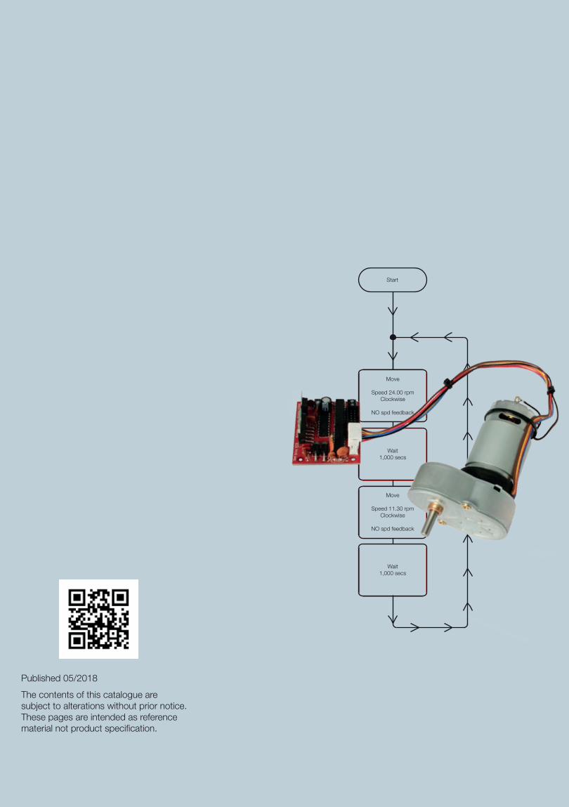
Start
Move
Speed 24.00 rpmClockwise
NO spd feedback
Wait1,000 secs
Move
Speed 11.30 rpmClockwise
NO spd feedback
Wait1,000 secs
Published 05/2018
The contents of this catalogue are subject to alterations without prior notice. These pages are intended as reference material not product specification.
Miniature Motors,Transmission and Control
Contact:[email protected]: +44 (0)1460 72000
Rotalink LimitedCropmead, CrewkerneSomerset TA18 7HQ, UK
www.rotalink.com
FM 24735