Embed Size (px)
Citation preview
Mini Pool Heat Pump
Mini Bomba de calor para piscinas
Мини термопомпа за басейн
SILENP-03
SILENP-04
SILENP-05
Muchas gracias por adquirir nuestro producto. Por favor, guarde y lea este manual
cuidadosamente antes de instalar la bomba de calor.
Thank you very much for purchasing our product. Please keep and read this manual
carefully before you install heat pump.
Благодарим ви, че закупихте нашия продукт. Моля, съхранявайте това
ръководство и го прочетете внимателно преди да монтирате термопомпата.
Ръководство за експлоатация
Operation
manual
Manual de instrucciones

Conserve el manual de instalación y léalo detenidamente antes de utilizarlo.
- La unidad debe ser instalada por personal profesional y basarse en este manual.
- Si la unidad se instala en un lugar vulnerable a la caída de rayos, deben tomarse medidas de protección contra
los rayos.
- El fabricante declina toda responsabilidad por los daños causados a las personas, a los objetos y por los errores
debidos a la instalación que desobedezca las directrices del manual. Cualquier uso que no sea conforme en el
origen de su fabricación será considerado como peligroso.
- Por favor, mantenga siempre la bomba de calor en un lugar ventilado y alejado de cualquier cosa que pueda
provocar un incendio.
- No suelde la tubería si hay refrigerante dentro de la máquina. Por favor, mantenga la máquina fuera del espacio
confinado cuando haga el llenado de gas.
- Por favor, vacíe siempre el agua de la bomba de calor durante el invierno o cuando la temperatura ambiente
sea inferior a 0℃, de lo contrario el intercambiador de titanio se dañará debido a la congelación, en tal caso,
quedará fuera de garantía para esta máquina.
- Por favor, corte siempre el suministro eléctrico si quiere abrir el armario para acceder al interior de la bomba
de calor, ya que hay electricidad de alto voltaje en el interior.
- Por favor, mantenga el controlador de la pantalla en un área seca para proteger el controlador de la pantalla de
ser dañado por la humedad.
- La acción de llenar el gas debe ser realizada por un profesional con licencia de operación R32.
* ÍNDICE
1. Especificaciones
2. Dimensión
3. Instalación y conexión
4. Cableado eléctrico
5. Funcionamiento del controlador de la pantalla
6. Solución de problemas
7. Diagrama de despiece
8. Mantenimiento

1. Especificaciones
1.1 Datos técnicos de las bombas de calor para piscinas
Modelo No. SILENP-03 SILENP-04 SILENP-05
Fuente de alimentación 220V~240V/1/50Hz
Capacidad de calentamiento a 26°C de aire, 26°C de agua, 80% de humedad
Capacidad de calentamiento (W) 3050 4100 5020
Potencia de entrada (W) 560 756 937
COP 5.45 5.42 5.36
Capacidad de calentamiento a 15°C de aire, 26°C de agua, 70% de humedad
Capacidad de calentamiento (kW) 2510 3250 4080
Potencia de entrada (kW) 554 719 932
COP 4.53 4.52 4.38
Potencia máxima de entrada (kW) 950 1280 1550
Corriente máxima (A) 4.4 5.8 7.0
Refrigerante R32 R32 R32
Intercambiador de calor Titanio Titanio Titanio
Dirección del flujo de aire Horizontal Horizontal Horizontal
Volumen de flujo de agua (m3/h) 1.5 2.0 2.5
Dimensiones netas (L*A*H) (mm) 400*285*350 400*285*350 400*285*400
Dimensiones del paquete (L*A*H) (mm)
460*370*400 460*370*400 460*370*450
Rango de temperatura de trabajo (°C)
11~43 11~43 11~43
Ruido (dB) 28 29 29
Peso neto (kg) 18 18 18
Peso bruto (kg) 20 20 20
*Los datos anteriores están sujetos a modificaciones sin previo aviso.

2. Dimensiones (mm)
SILENP-03/04
SILENP-05
3. Instalación y conexión
Atención:
Tenga en cuenta las siguientes normas al instalar la bomba de calor:
1. Cualquier adición de productos químicos debe realizarse en las tuberías situadas a continuación de la
bomba de calor.
2. Mantenga siempre la bomba de calor en posición vertical. Si la unidad se ha sujetado en ángulo, espere
al menos 24 horas antes de poner en marcha la bomba de calor.
3.1 Ubicación de la bomba de calor
La unidad funcionará correctamente en cualquier ubicación deseada siempre que estén presentes los tres
elementos siguientes:
1. Aire fresco – 2. Electricidad – 3. Filtros de piscina

La unidad puede instalarse prácticamente en cualquier lugar exterior siempre que se mantengan las distancias
mínimas especificadas a otros objetos. Consulte a su instalador para la instalación con una piscina interior.
ATENCIÓN: No instale nunca la unidad en una habitación cerrada con un volumen de aire limitado en la que se
vaya a reutilizar el aire expulsado de la unidad, ni cerca de arbustos que puedan bloquear la entrada de aire. Tales
ubicaciones perjudican el suministro continuo de aire fresco, lo que resulta en una reducción de la eficiencia y
posiblemente impide una salida de calor suficiente.
3.2 Funcionamiento inicial
Nota: Para calentar el agua de la piscina (o bañera de hidromasaje), la bomba del filtro debe estar en
funcionamiento para que el agua circule por la bomba de calor. La bomba de calor no se pondrá en marcha si el
agua no circula
3.3 Conexión eléctrica
Antes de conectar la unidad, compruebe que la tensión de alimentación coincide con la tensión de
funcionamiento de la bomba de calor.
El enchufe RCD se ha incluido con el cable de alimentación, que puede ofrecer protección eléctrica.
Atención:
Asegúrese de que el enchufe está
bien sujeto
Si el enchufe no está bien sujeto,
puede provocar una descarga
eléctrica, un sobrecalentamiento o
un incendio
No desconecte nunca el enchufe
durante el funcionamiento.
De lo contrario, podría provocar una descarga eléctrica o un incendio por
sobrecalentamiento.
No utilice nunca cables eléctricos
dañados o no especificados.
De lo contrario, podría provocar una descarga eléctrica o un
incendio.
Una vez realizadas y comprobadas todas las conexiones, realice el siguiente procedimiento:
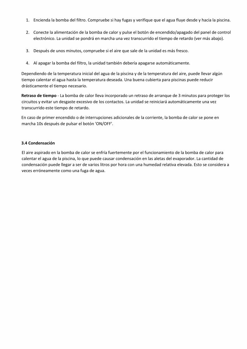
1. Encienda la bomba del filtro. Compruebe si hay fugas y verifique que el agua fluye desde y hacia la piscina.
2. Conecte la alimentación de la bomba de calor y pulse el botón de encendido/apagado del panel de control
electrónico. La unidad se pondrá en marcha una vez transcurrido el tiempo de retardo (ver más abajo).
3. Después de unos minutos, compruebe si el aire que sale de la unidad es más fresco.
4. Al apagar la bomba del filtro, la unidad también debería apagarse automáticamente.
Dependiendo de la temperatura inicial del agua de la piscina y de la temperatura del aire, puede llevar algún
tiempo calentar el agua hasta la temperatura deseada. Una buena cubierta para piscinas puede reducir
drásticamente el tiempo necesario.
Retraso de tiempo - La bomba de calor lleva incorporado un retraso de arranque de 3 minutos para proteger los
circuitos y evitar un desgaste excesivo de los contactos. La unidad se reiniciará automáticamente una vez
transcurrido este tiempo de retardo.
En caso de primer encendido o de interrupciones adicionales de la corriente, la bomba de calor se pone en
marcha 10s después de pulsar el botón 'ON/OFF'.
3.4 Condensación
El aire aspirado en la bomba de calor se enfría fuertemente por el funcionamiento de la bomba de calor para
calentar el agua de la piscina, lo que puede causar condensación en las aletas del evaporador. La cantidad de
condensación puede llegar a ser de varios litros por hora con una humedad relativa elevada. Esto se considera a
veces erróneamente como una fuga de agua.
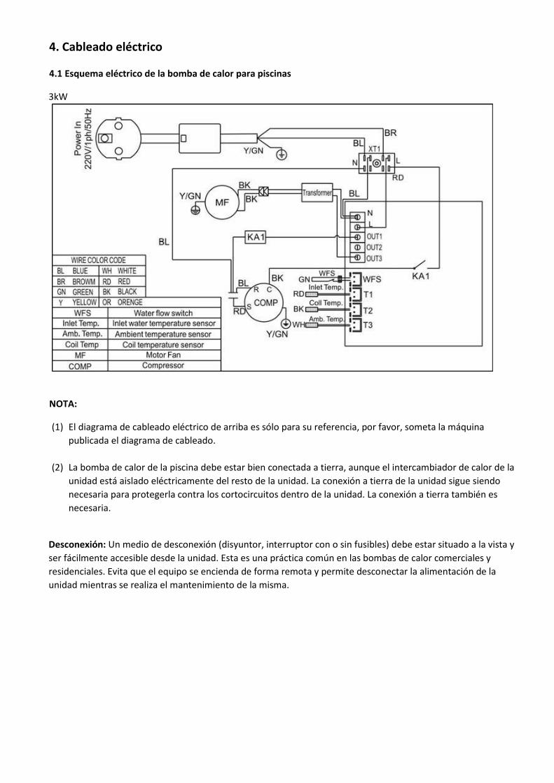
4. Cableado eléctrico
4.1 Esquema eléctrico de la bomba de calor para piscinas
3kW
NOTA:
(1) El diagrama de cableado eléctrico de arriba es sólo para su referencia, por favor, someta la máquina
publicada el diagrama de cableado.
(2) La bomba de calor de la piscina debe estar bien conectada a tierra, aunque el intercambiador de calor de la
unidad está aislado eléctricamente del resto de la unidad. La conexión a tierra de la unidad sigue siendo
necesaria para protegerla contra los cortocircuitos dentro de la unidad. La conexión a tierra también es
necesaria.
Desconexión: Un medio de desconexión (disyuntor, interruptor con o sin fusibles) debe estar situado a la vista y
ser fácilmente accesible desde la unidad. Esta es una práctica común en las bombas de calor comerciales y
residenciales. Evita que el equipo se encienda de forma remota y permite desconectar la alimentación de la
unidad mientras se realiza el mantenimiento de la misma.

5. Funcionamiento del controlador de la pantalla 5.1 La interfaz del controlador de cables LED
* Cuando la bomba de calor está en funcionamiento o en espera, la pantalla muestra la temperatura de
entrada del agua.
* Cuando la bomba de calor está encendida, la pantalla muestra "OFF"
* El LED rojo se encenderá al encender la máquina.
5.2 Encender/apagar la bomba de calor
Pulse para encender la bomba de calor, la pantalla LED muestra la temperatura de ajuste del agua durante
5s, luego muestra la temperatura de entrada del agua.
Pulse de nuevo para apagar la bomba de calor.
NOTA: Hay 3 minutos de protección de retardo para el compresor.
5.3 Ajustar la temperatura del agua deseada
Pulse directamente para ajustar la temperatura del agua deseada (parámetro de rango:.15-40℃),
los datos se guardarán en 3 segundos.
O puede ajustar el parámetro d para establecer la temperatura del agua deseada.
NOTA: la bomba de calor sólo puede funcionar si el sistema de círculo de agua/filtración está en marcha.
5.4 Comprobación y ajuste de parámetros
Mantenga pulsado el botón durante 5 segundos, y entrará en la comprobación de parámetros,
Pulse para comprobar los siguientes parámetros.
o
O
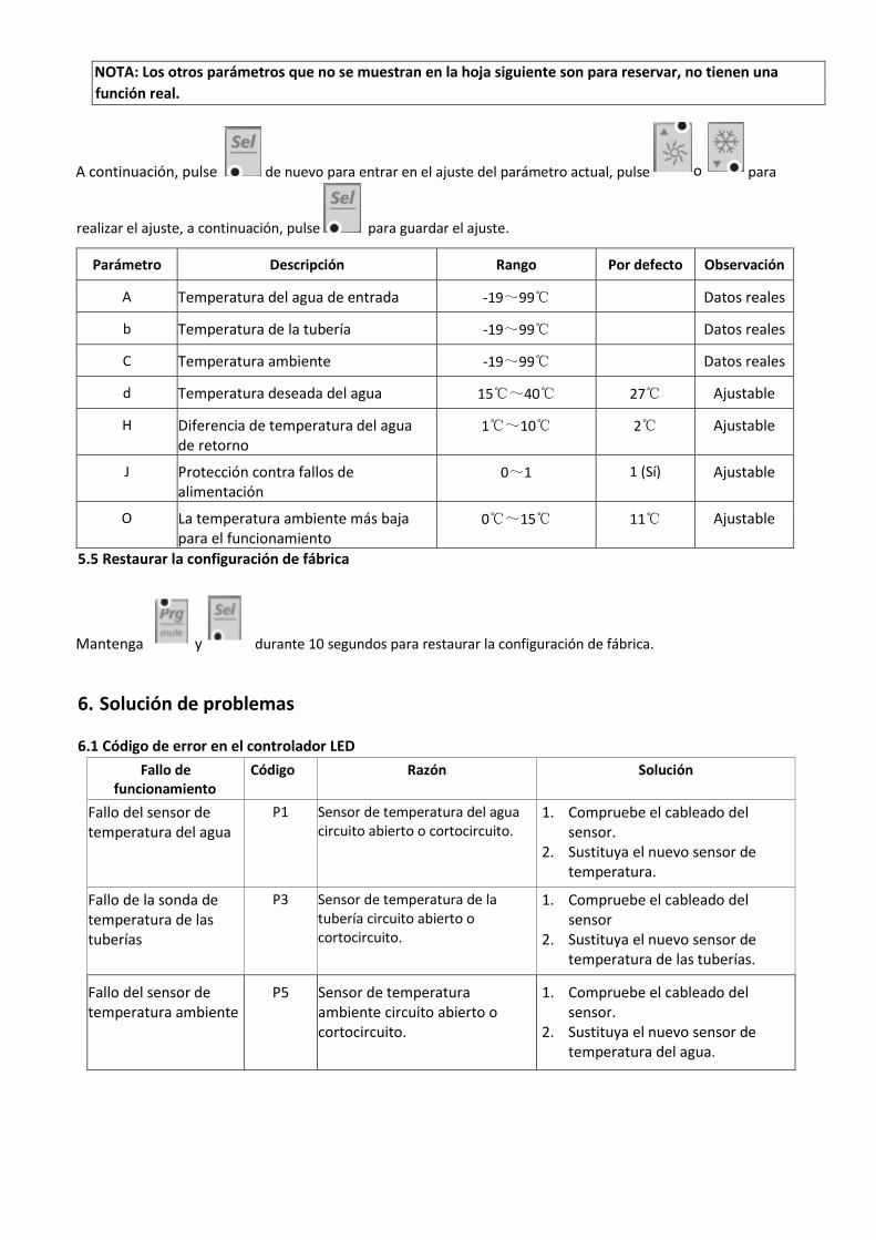
NOTA: Los otros parámetros que no se muestran en la hoja siguiente son para reservar, no tienen una
función real.
A continuación, pulse de nuevo para entrar en el ajuste del parámetro actual, pulse para
realizar el ajuste, a continuación, pulse para guardar el ajuste.
Parámetro Descripción Rango Por defecto Observación
A Temperatura del agua de entrada -19~99℃ Datos reales
b Temperatura de la tubería -19~99℃ Datos reales
C Temperatura ambiente -19~99℃ Datos reales
d Temperatura deseada del agua 15℃~40℃ 27℃ Ajustable
H Diferencia de temperatura del agua de retorno
1℃~10℃ 2℃ Ajustable
J Protección contra fallos de alimentación
0~1 1 (Sí) Ajustable
O La temperatura ambiente más baja para el funcionamiento
0℃~15℃ 11℃ Ajustable
5.5 Restaurar la configuración de fábrica
Mantenga y durante 10 segundos para restaurar la configuración de fábrica.
6. Solución de problemas
6.1 Código de error en el controlador LED
Fallo de funcionamiento
Código Razón Solución
Fallo del sensor de temperatura del agua
P1 Sensor de temperatura del agua circuito abierto o cortocircuito.
1. Compruebe el cableado del sensor.
2. Sustituya el nuevo sensor de temperatura.
Fallo de la sonda de temperatura de las tuberías
P3 Sensor de temperatura de la tubería circuito abierto o cortocircuito.
1. Compruebe el cableado del sensor
2. Sustituya el nuevo sensor de temperatura de las tuberías.
Fallo del sensor de temperatura ambiente
P5 Sensor de temperatura ambiente circuito abierto o cortocircuito.
1. Compruebe el cableado del sensor.
2. Sustituya el nuevo sensor de temperatura del agua.
o
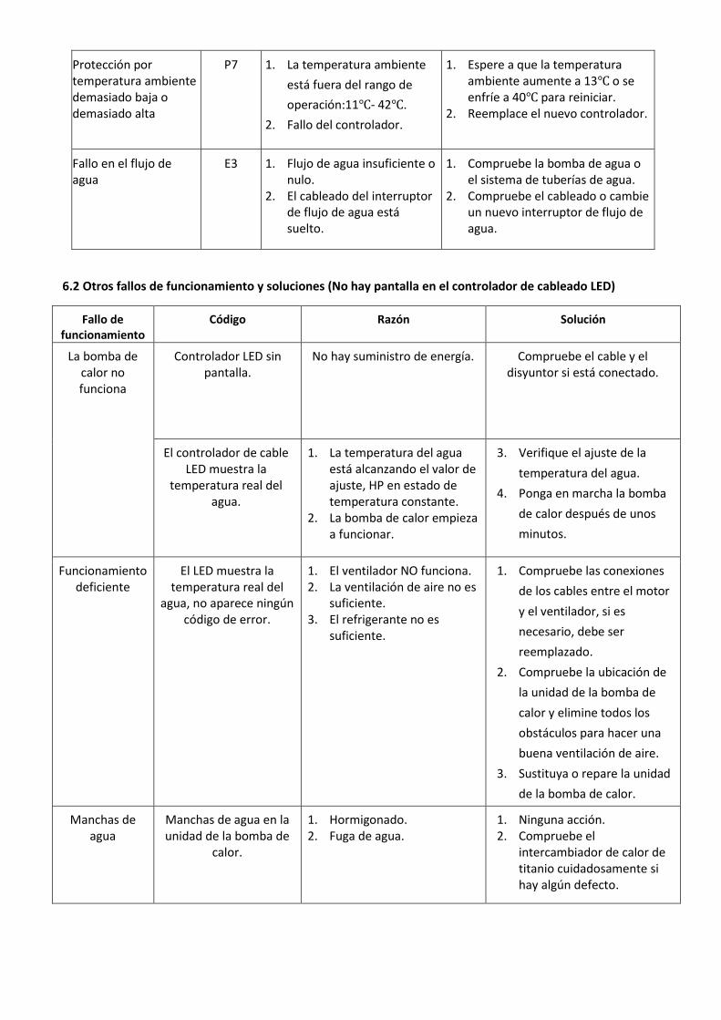
Protección por temperatura ambiente demasiado baja o demasiado alta
P7 1. La temperatura ambiente
está fuera del rango de
operación:11℃- 42℃.
2. Fallo del controlador.
1. Espere a que la temperatura ambiente aumente a 13℃ o se enfríe a 40℃ para reiniciar.
2. Reemplace el nuevo controlador.
Fallo en el flujo de agua
E3 1. Flujo de agua insuficiente o nulo.
2. El cableado del interruptor de flujo de agua está suelto.
1. Compruebe la bomba de agua o el sistema de tuberías de agua.
2. Compruebe el cableado o cambie un nuevo interruptor de flujo de agua.
6.2 Otros fallos de funcionamiento y soluciones (No hay pantalla en el controlador de cableado LED)
Fallo de funcionamiento
Código Razón Solución
La bomba de calor no funciona
Controlador LED sin pantalla.
No hay suministro de energía. Compruebe el cable y el disyuntor si está conectado.
El controlador de cable LED muestra la
temperatura real del agua.
1. La temperatura del agua está alcanzando el valor de ajuste, HP en estado de temperatura constante.
2. La bomba de calor empieza a funcionar.
3. Verifique el ajuste de la
temperatura del agua.
4. Ponga en marcha la bomba
de calor después de unos
minutos.
Funcionamiento deficiente
El LED muestra la temperatura real del
agua, no aparece ningún código de error.
1. El ventilador NO funciona. 2. La ventilación de aire no es
suficiente. 3. El refrigerante no es
suficiente.
1. Compruebe las conexiones
de los cables entre el motor
y el ventilador, si es
necesario, debe ser
reemplazado.
2. Compruebe la ubicación de
la unidad de la bomba de
calor y elimine todos los
obstáculos para hacer una
buena ventilación de aire.
3. Sustituya o repare la unidad
de la bomba de calor.
Manchas de agua
Manchas de agua en la unidad de la bomba de
calor.
1. Hormigonado. 2. Fuga de agua.
1. Ninguna acción. 2. Compruebe el
intercambiador de calor de titanio cuidadosamente si hay algún defecto.

7. Diagrama de despiece
No. Nombre No. Nombre
1 Bandeja base 9 Intercambiador de calor de titanio
2 Panel frontal 10 Interruptor de flujo de agua
3 Pilar trasero 11 Condensador
4 Aspa del ventilador
12 Interruptor
5 Rejilla del ventilador
13 Controlador
6 Tornillo M4 14 Elevador
7 Compresor 15 Elevador
8 Evaporador 16 Tapa superior

8. Mantenimiento
(1) Debe revisar el sistema de suministro de agua regularmente para evitar la entrada de aire en el sistema y
la aparición de un bajo flujo de agua, ya que reduciría el rendimiento y la fiabilidad de la unidad HP.
(2) Limpie las piscinas y el sistema de filtración regularmente para evitar el daño de la unidad como
resultado de la suciedad del filtro obstruido.
(3) Debe descargar el agua de la bomba de calor si deja de funcionar durante mucho tiempo (especialmente
durante la temporada de invierno).
(4) También debe comprobar que la unidad está completamente llena de agua antes de que empiece a
funcionar de nuevo.
(5) Cuando la unidad está en funcionamiento, siempre hay una pequeña descarga de agua debajo de la
unidad.
Please keep installation manual properlyand read itcarefully before using.
- The unit must be installed by professional personnel, and install it based on this manual as possible.
- If the unit would be installed where is vulnerable to lightningstroke, lightning protectionmeasurements must be
carried out.
- The manufacturer declines any responsibility for the damage caused with the people, objects and of the errors
due to the installation that disobey the manual guideline. Any use that is without conformity at the origin of its
manufacturing will be regarded as dangerous.
- Please always keep the heat pump in the ventilation place and away from anything which could cause fire.
- Don’t weld the pipe if there is refrigerant inside machine. Please keep the machine out of the confined space
when make gas filling.
- Please always empty the water in heat pump during winter time or when the ambient temperature drops below
0℃, or else the Titanium exchanger will be damaged because of being frozen, in such case, it will be out of
warranty for this machine.
- Please always cut the power supply if you want to open the cabinet to reach inside the heat pump, because there
is high voltage electricity inside.
- Please well keep the display controller in a dry area to protect the display controller from being damaged by
humidity.
- Action of filling gas must be conducted by professional with R32 operating license.
* INDEX
1. Specifications
2. Dimension
3. Installation and connection
4. Electrical wiring
5. Display controller operation
6. Trouble shooting
7. Exploded diagram
8. Maintenance

1. Specifications
1.1 Technical data pool heat pumps
Model No. SILENP-03 SILENP-04 SILENP-05
Power Supply 220V~240V/1/50Hz
Heating Capacity at Air 26°C, Water 26°C, Hygro 80%
Heating Capacity (W) 3050 4100 5020
Power Input (W) 560 756 937
COP 5.45 5.42 5.36
Heating Capacity at Air 15°C, Water 26°C, Hygro 70%
Heating Capacity (kW) 2510 3250 4080
Power Input (kW) 554 719 932
COP 4.53 4.52 4.38
Max Power Input (kW) 950 1280 1550
Max Current (A) 4.4 5.8 7.0
Refrigerant R32 R32 R32
Heat Exchanger Titanium Titanium Titanium
Air Flow Direction Horizotal Horizotal Horizotal
Water Flow Volume (m3/h) 1.5 2.0 2.5
Net Dimensions (L*W*H) (mm) 400*285*350 400*285*350 400*285*400
Package Dimensions(L*W*H) (mm) 460*370*400 460*370*400 460*370*450
Working temperature range (°C) 11~43 11~43 11~43
Noise (dB) 28 29 29
Net Weight (kg) 18 18 18
Gross Weight (kg) 20 20 20
*Above data is subject to modification without prior notice.
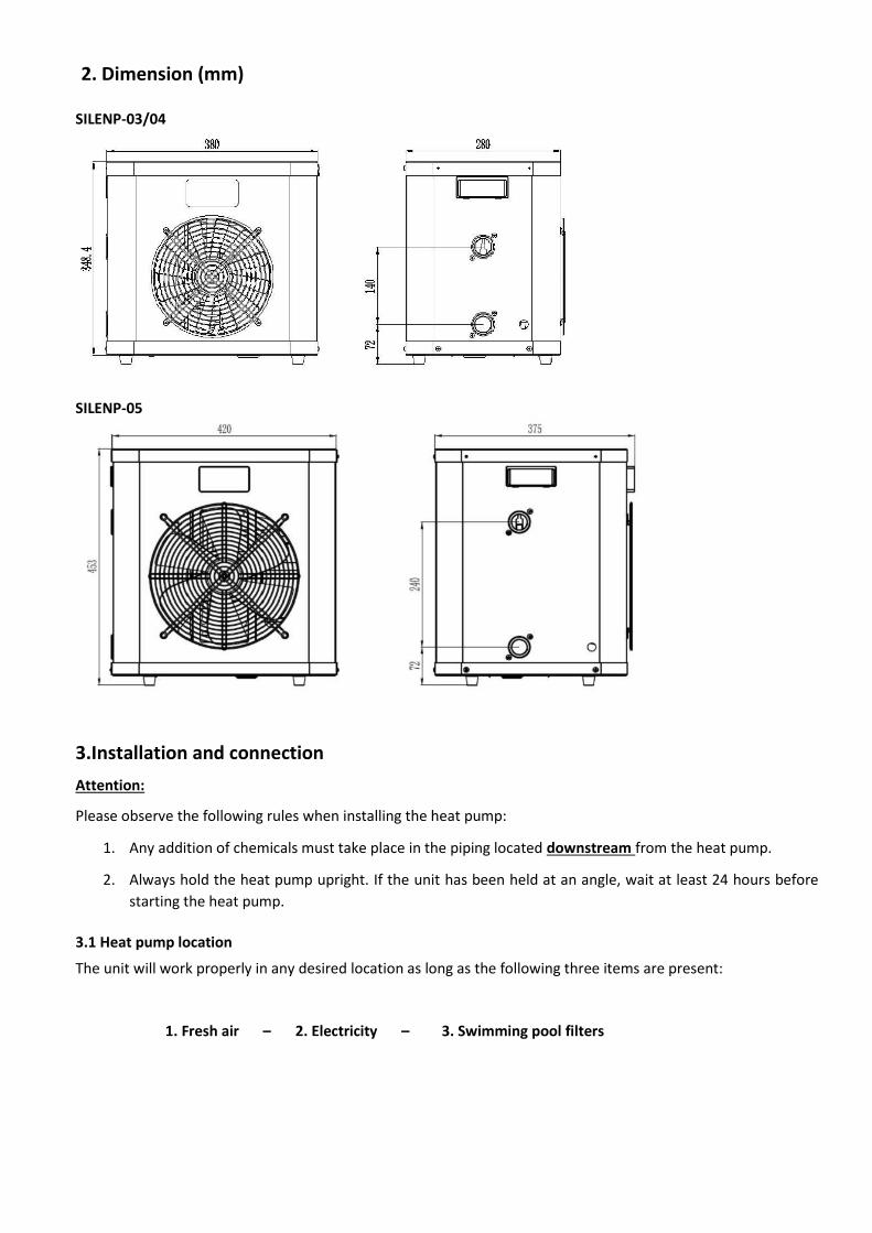
2. Dimension (mm)
SILENP-03/04
SILENP-05
3.Installation and connection
Attention:
Please observe the following rules when installing the heat pump:
1. Any addition of chemicals must take place in the piping located downstream from the heat pump.
2. Always hold the heat pump upright. If the unit has been held at an angle, wait at least 24 hours before
starting the heat pump.
3.1 Heat pump location
The unit will work properly in any desired location as long as the following three items are present:
1. Fresh air – 2. Electricity – 3. Swimming pool filters

The unit may be installed in virtually any outdoor location as long as the specified minimum distances to other
objects are maintained. Please consult your installer for installation with an indoor pool.
ATTENTION: Never install the unit in a closed room with a limited air volume in which the air expelled from the
unit will be reused, or close to shrubbery that could block the air inlet. Such locations impair the continuous supply
of fresh air, resulting in reduced efficiency and possibly preventing sufficient heat output.
3.2 Initial operation
Note: In order to heat the water in the pool (or hot tub), the filter pump must be running to cause the water to
circulate through the heat pump. The heat pump will not start up if the water is not circulating.
3.3 Electrical connection
Before connecting the unit, verify that the supply voltage matches the operating voltage of the heat pump.
The RCD plug has been included with power cable, which can offer electrical protection.
Attention:
Ensure the power plug is secure
If the plug is not secure, it may cause
an electric shock, over-heating or
fire
Never pull out the power plug during
operation
Otherwise, it may cause an electric
shock or a fire due to over-heating.
Never use damaged electric wires
or unspecified electric wires.
Otherwise it may cause an electric
shock or a fire.

After all connections have been made and checked, carry out the following procedure:
1. Switch on the filter pump. Check for leaks and verify that water is flowing from and to the swimming pool.
2. Connect power to the heat pump and press the On/Off button on the electronic control panel. The unit will
start up after the time delay expires (see below).
3. After a few minutes, check whether the air blowing out of the unit is cooler.
4. When turn off the filter pump, the unit should also turn off automatically.
Depending on the initial temperature of the water in the swimming pool and the air temperature, it may take some
time to heat the water to the desired temperature. A good swimming pool cover can dramatically reduce the
required length of time.
Time delay - The heat pump has a built-in 3-minute start-up delay to protect the circuitry and avoid excessive
contact wear. The unit will restart automatically after this time delay expires.
If first power on or additional power interruptions, the heat pump starts 10s later after pressing ‘ON/OFF’ button.
3.4 Condensation
The air drawn into the heat pump is strongly cooled by the operation of the heat pump for heating the pool water,
which may cause condensation on the fins of the evaporator. The amount of condensation may be as much as
several litters per hour at high relative humidity. This is sometimes mistakenly regarded as a water leak.

4. Electrical wiring
4.1 Swimming pool heat pump wiring diagram
3kW
NOTE:
(1) Above electrical wiring diagram only for your reference, please subject machine posted the wiring diagram.
(2) The swimming pool heat pump must be connected ground wire well, although the unit heat exchanger is
electrically isolated from the rest of the unit. Grounding the unit is still required to protect you against short
circuits inside the unit. Bonding is also required.
Disconnect: A disconnect means (circuit breaker, fused or un-fused switch) should be located within sight of and
readily accessible from the unit. This is common practice on commercial and residential heat pumps. It prevents
remotely-energizing unattended equipment and permits turning off power at the unit while the unit is being
serviced.
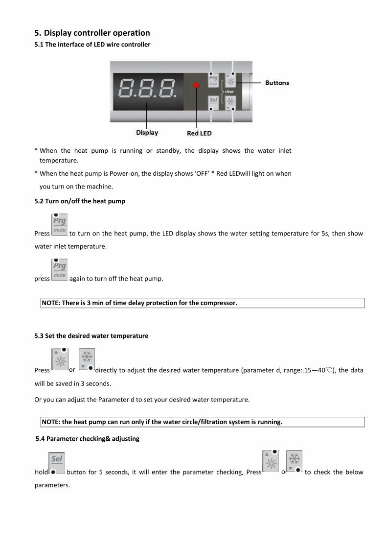
5. Display controller operation 5.1 The interface of LED wire controller
* When the heat pump is running or standby, the display shows the water inlet
temperature.
* When the heat pump is Power-on, the display shows ‘OFF’ * Red LEDwill light on when
you turn on the machine.
5.2 Turn on/off the heat pump
Press to turn on the heat pump, the LED display shows the water setting temperature for 5s, then show
water inlet temperature.
press again to turn off the heat pump.
NOTE: There is 3 min of time delay protection for the compressor.
5.3 Set the desired water temperature
Press directly to adjust the desired water temperature (parameter d, range:.15—40℃), the data
will be saved in 3 seconds.
Or you can adjust the Parameter d to set your desired water temperature.
NOTE: the heat pump can run only if the water circle/filtration system is running.
5.4 Parameter checking& adjusting
Hold button for 5 seconds, it will enter the parameter checking, Press to check the below
parameters.
or
or
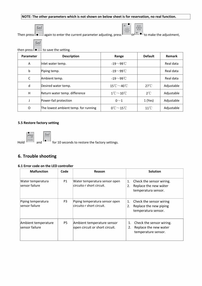
NOTE: The other parameters which is not shown on below sheet is for reservation, no real function.
Then press again to enter the current parameter adjusting, press to make the adjustment,
then press to save the setting.
Parameter Description Range Default Remark
A Inlet water temp. -19~99℃ Real data
b Piping temp. -19~99℃ Real data
C Ambient temp. -19~99℃ Real data
d Desired water temp. 15℃~40℃ 27℃ Adjustable
H Return water temp. difference 1℃~10℃ 2℃ Adjustable
J Power-fail protection 0~1 1 (Yes) Adjustable
O The lowest ambient temp. for running 0℃~15℃ 11℃ Adjustable
5.5 Restore factory setting
Hold and for 10 seconds to restore the factory settings.
6. Trouble shooting
6.1 Error code on the LED controller
Malfunction Code Reason Solution
Water temperatura sensor failure
P1 Water temperatura sensor open circuito r short circuit.
1. Check the sensor wiring. 2. Replace the new wáter
temperatura sensor.
Piping temperatura sensor failure
P3 Piping temperatura sensor open circuito r short circuit.
1. Check the sensor wiring 2. Replace the new piping
temperatura sensor.
Ambient temperature sensor failure
P5 Ambient temperature sensor open circuit or short circuit.
1. Check the sensor wiring. 2. Replace the new water
temperature sensor.
or
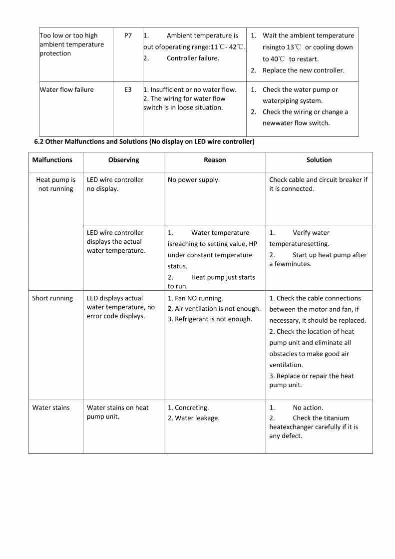
Too low or too high ambient temperature protection
P7 1. Ambient temperature is
out ofoperating range:11℃- 42℃.
2. Controller failure.
1. Wait the ambient temperature
risingto 13℃ or cooling down
to 40℃ to restart.
2. Replace the new controller.
Water flow failure E3 1. Insufficient or no water flow. 2. The wiring for water flow switch is in loose situation.
1. Check the water pump or
waterpiping system.
2. Check the wiring or change a
newwater flow switch.
6.2 Other Malfunctions and Solutions (No display on LED wire controller)
Malfunctions Observing Reason Solution
Heat pump is not running
LED wire controller no display.
No power supply. Check cable and circuit breaker if it is connected.
LED wire controller displays the actual water temperature.
1. Water temperature
isreaching to setting value, HP
under constant temperature
status.
2. Heat pump just starts to run.
1. Verify water
temperaturesetting.
2. Start up heat pump after a fewminutes.
Short running LED displays actual water temperature, no error code displays.
1. Fan NO running.
2. Air ventilation is not enough.
3. Refrigerant is not enough.
1. Check the cable connections
between the motor and fan, if
necessary, it should be replaced.
2. Check the location of heat
pump unit and eliminate all
obstacles to make good air
ventilation.
3. Replace or repair the heat pump unit.
Water stains Water stains on heat pump unit.
1. Concreting.
2. Water leakage.
1. No action.
2. Check the titanium heatexchanger carefully if it is any defect.

7. Exploded diagram
No. Name No. Name
1 Base tray 9 Titanium heat exchanger
2 Front panel 10 Water flow switch
3 Back pillar 11 Capacitor
4 Fan blade 12 Switch
5 Fan grill 13 Controller
6 M4 screw 14 Lift
7 Compressor 15 Lift
8 Evaporator 16 Top cover

8. Maintenance
(1) You should check the water supply system regularly to avoid the air entering the system and occurrence of low
water flow, because it would reduce the performance and reliability of HP unit.
(2) Clean your pools and filtration system regularly to avoid the damage of the unit as a result of the dirty of
clogged filter.
(3) You should discharge the water from heat pump if it will stop running for a long time (especially during the
winter season).
(4) In another way, you should check the unit is water fully before the unit start to run again.
(5) When the unit is running, there is all the time a little water discharge under the unit.

Моля, съхранявайте това ръководство и го прочетете внимателно преди да монтирате
термопомпата.
- Машината трябва да се монтира от професионален и оторизиран персонал в съответствие с инструкциите
в това ръководство.
- Ако машината ще се монтира на места, на които съществува риск от гръмотевичен удар, трябва да се
вземат необходимите мерки за мълниезащита.
- Производителят не носи отговорност за повреди или наранявания, причинени от неправилно извършена
инсталация. Експлоатацията на машината не по предназначение се счита за опасна.
- Локацията, на която се монтира термопомпата, трябва да е добре вентилирана и в близост да няма
запалими източници.
- Не извършвайте заваръчни дейности по тръбите докато в тях има хладилен агент. Машината не трябва да
се намира в затворено помещение при зареждане с хладилен агент.
- По време на зимния период или в дни с температури под 0°C водата в термопомпата трябва да бъде
източена, в противен случай съществува опасност титаниевият топлообенник да замръзне и да се повреди,
което няма да бъде покрито от гаранцията.
- Преди отваряне на капака на термопомпата електрическото захранване винаги трябва да е прекъснато.
- Управлението трябва да се постави на сухо място за да бъде защитено от влажността.
- Дейностите по зареждане с хладилен агент трябва да се извършват от професионален персонал,
лицензиран за работа с R32.
СЪДЪРЖАНИЕ
1. Спецификации
2. Размери
3. Монтаж и свързване
4. Електрическо свързване
5. Работа с управлението
6. Най-често срещани грешки
7. Изглед на елементите на машината
8. Поддръжка

1. Спецификации
1.1 Технически данни
Модел SILENP-03 SILENP-04 SILENP-05
Захранване 220V~240V/1/50Hz
Отоплителна мощност при температура на въздух 26°C, вода 26°C, влажност 80%
Отоплителна мощност (W) 3050 4100 5020
Консумирана мощност (W) 560 756 937
COP 5.45 5.42 5.36
Отоплителна мощност при температура на въздух 15°C, вода 26°C, влажност 70%
Отоплителна мощност (W) 2510 3250 4080
Консумирана мощност (W) 554 719 932
COP 4.53 4.52 4.38
Макс. консумирана мощност (kW) 950 1280 1550
Макс. ток (A) 4.4 5.8 7.0
Хладилен агент R32 R32 R32
Топлообменник Титан Титан Титан
Посока на въздушен поток Horizotal Horizotal Horizotal
Воден дебит (m3/h) 1.5 2.0 2.5
Размери (L*W*H) (mm) 400*285*350 400*285*350 400*285*400
Размери на опаковка (L*W*H) (mm) 460*370*400 460*370*400 460*370*450
Работна температура (°C) 11~43 11~43 11~43
Шумово ниво (dB) 28 29 29
Нетно тегло (kg) 18 18 18
Брутно тегло (kg) 20 20 20
*Запазваме си правото да променяме данните по-горе без предварително уведомление.

2. Размери (mm)
SILENP-03/04
SILENP-05
3.Монтаж и свързване
Внимание:
При монтаж на термпомпата спазвайте следните указания:
3. Добавянето на химически вещества трябва да се прави в тръбите, разположени след термопомпата.
4. Термопомпата трябва да стои винаги изправена. Ако е била наклонена под ъгъл, трябва да изчакате
поне 24 часа преди да я стартирате.
3.1 Локация на термопомпа
На мястото за монтаж трябва да са налични следните три елемента:
1. Пресен въздух – 2. Електрически ток – 3. Филтри за басейни
Машината може да се монтира във всяка локация на открито стига да са спазени минималните отстояния
от други обекти. Ако се налага монтаж в басейни на закрито, консултирайте се с монтажната фирма.
ВНИМАНИЕ: Машината не трябва да се монтира в затворено помещение с ограничен достъп до въздух, в
което отработеният въздух ще се използва повторно, или в близост до растителност, която да блокира
въздушните отвори. Тези локации ограничават достъпа на пресен въздух, което води до намалена
ефективност и ограничаване на отоплителната мощност.
3.2 Първоначално стартиране
Забележка: За да се стартира машината, филтърната помпа трябва да работи, за да циркулира водата
през термопомпата. Термопомпата няма да се стартира ако водата не циркулира.
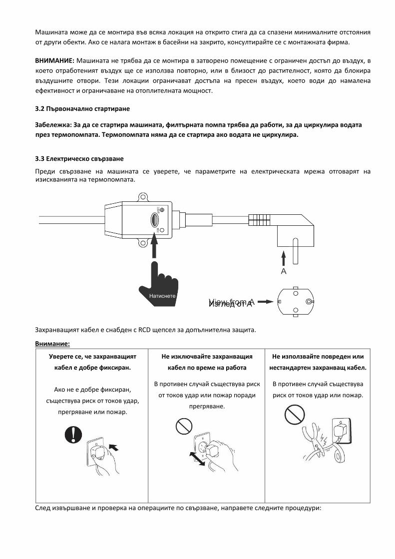
3.3 Електрическо свързване
Преди свързване на машината се уверете, че параметрите на електрическата мрежа отговарят на изискванията на термопомпата.
Захранващият кабел е снабден с RCD щепсел за допълнителна защита.
Внимание:
Уверете се, че захранващият
кабел е добре фиксиран.
Ако не е добре фиксиран,
съществува риск от токов удар,
прегряване или пожар.
Не изключвайте захранващия
кабел по време на работа
В противен случай съществува риск
от токов удар или пожар поради
прегряване.
Не използвайте повреден или
нестандартен захранващ кабел.
В противен случай съществува
риск от токов удар или пожар.
След извършване и проверка на операциите по свързване, направете следните процедури:
Натиснете Изглед от A
1. Включете филтърната помпа. Проверете за пропуски и се уверете, че водата протича свободно от и към
басейна.
2. Свържете захранването към термопомпата и натиснете бутона On/Off на електронния панел за
управление. След кратко забавяне машината ще се стартира (вижте по-долу).
3. След няколко минути проверете дали въздухът, излизащ от машината е по-студен.
4. При изключване на филтърната помпа машината автоматично ще се изключи.
Нагряването на водата до желаната температура може да отмене известно време в зависимост от началната
температура на водата в басейна и температурата на въздуха. Това време може да бъде намалено ако
басейнът е оборудван с покривало.
Забавяне - Термопомпата е с вграден отложен старт от 3 минути, чиято функция е да предпазва машината
и да я защитава от износване. След изтичането на периода на отложения старт машината ще се
рестартира автоматично.
При прекъсвания на електрическото захранване термопомпата ще се стартира 10 секунди след натискането
на бутона ‘ON/OFF’.
3.4 Конденз
По време на нагряване на водата за басейна засмуканият в термопомпата въздух силно се охлажда, което
може да доведе до образуване на конденз по ламелите на топлообменника. Количеството конденз може
да достигне до няколко литра на час при висока относителна влажност на въздуха. Това понякога може да бъде погрешно счетено за теч на вода.
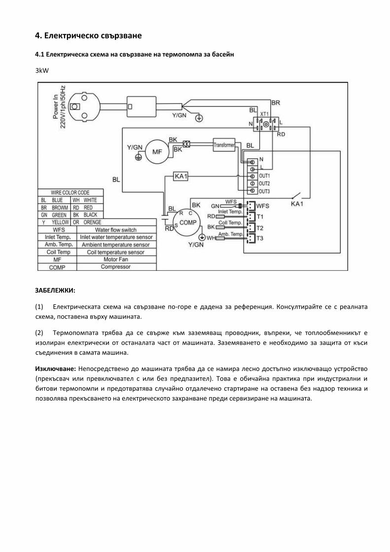
4. Електрическо свързване
4.1 Електрическа схема на свързване на термопомпа за басейн
3kW
ЗАБЕЛЕЖКИ:
(1) Електрическата схема на свързване по-горе е дадена за референция. Консултирайте се с реалната
схема, поставена върху машината.
(2) Термопомпата трябва да се свърже към заземяващ проводник, въпреки, че топлообменникът е
изолиран електрически от останалата част от машината. Заземяването е необходимо за защита от къси
съединения в самата машина.
Изключване: Непосредствено до машината трябва да се намира лесно достъпно изключващо устройство
(прекъсвач или превключвател с или без предпазител). Това е обичайна практика при индустриални и
битови термопомпи и предотвратява случайно отдалечено стартиране на оставена без надзор техника и
позволява прекъсването на електрическото захранване преди сервизиране на машината.

5. Работа с дисплея на контролера
5.1 Интерфейс на LED контролер
* Когато термопомпата се намира в standby режим, на дисплея ще се показва температурата на
водата на входа.
* Когато термопомпата е под електрическо захранване, на дисплея ще се показва ‘OFF’ * При
стартиране в работен режим на машината червеният LED индикатор ще светне.
5.2 Включване/изключване на термопомпата
Натиснете бутона за да включите термопомпата, на LED дисплея за 5 секунди ще се покаже
зададената стойност на температурата, след което ще се покаже стойността на температурата на входа.
Натиснете отново бутона за да изключите термопомпата.
ЗАБЕЛЕЖКА: Стартирането на машината е с вградено 3 минутно забавяне за защита на компресора.
5.3 Задаване на желанта стойност на температурата на водата
Натиснете бутоните за да настроите директно желаната стойност на температурата на
водата (параметър d, граници: 15 - 40°C), данните ще се запаметят след 3 секунди.
Или можете да настроите Параметър d за да зададете желаната стойност на температурата на водата.
ЗАБЕЛЕЖКА: Термопомпата може да работи само ако работят водният кръг/филтриращата система.
5.4 Проверка & настройка на параметри
Натиснете и задръжте за 5 секунди бутона за да влезете в екрана за проверка на параметри, след което
или
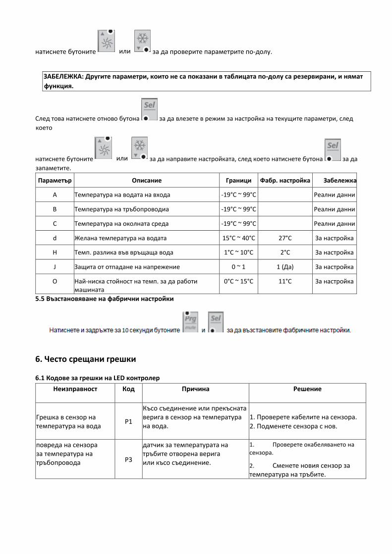
натиснете бутоните за да проверите параметрите по-долу.
ЗАБЕЛЕЖКА: Другите параметри, които не са показани в таблицата по-долу са резервирани, и нямат
функция.
След това натиснете отново бутона за да влезете в режим за настройка на текущите параметри, след
което
натиснете бутоните за да направите настройката, след което натиснете бутона за да
запаметите.
Параметър Описание Граници Фабр. настройка Забележка
A Температура на водата на входа -19°C ~ 99°C Реални данни
B Температура на тръбопроводиа -19°C ~ 99°C Реални данни
C Температура на околната среда -19°C ~ 99°C Реални данни
d Желана температура на водата 15°C ~ 40°C 27°C За настройка
H Темп. разлика във връщаща вода 1°C ~ 10°C 2°C За настройка
J Защита от отпадане на напрежение 0 ~ 1 1 (Да) За настройка
O Най-ниска стойност на темп. за да работи машината
0°C ~ 15°C 11°C За настройка
5.5 Възстановяване на фабрични настройки
6. Често срещани грешки
6.1 Кодове за грешки на LED контролер
Неизправност Код Причина Решение
Грешка в сензор на температура на вода
P1
Късо съединение или прекъсната верига в сензор на температура на вода.
1. Проверете кабелите на сензора.
2. Подменете сензора с нов.
повреда на сензора за температура на тръбопровода P3
датчик за температурата на тръбите отворена верига или късо съединение.
1. Проверете окабеляването на сензора.
2. Сменете новия сензор за температура на тръбите.
или
или
Грешка в сензор на температура на околна среда
P5 Късо съединение или прекъсната верига в сензор на температура на околна среда.
1. Проверете кабелите на сензора.
2. Подменете сензора с нов.
Защита от прекалено ниска или прекалено висока температура на околната среда.
P7
1. Температурата на
околната среда е извън
работните граници на машината:
11°C- 43°C.
2. Грешка в контролер.
1. Изчакайте температурата на
околната среда да се повиши до
13°C или да падне до 40°C за да
рестартирате.
2. Подменете контролера с нов.
Грешка в циркулация на вода
E3
1. Недостатъчна или липса
на циркулация на вода.
2. Кабелите за датчика поток са разхлабени.
1. Проверете водната помпа
или водната инсталация.
2. Проверете кабелите или подменете датчика поток.
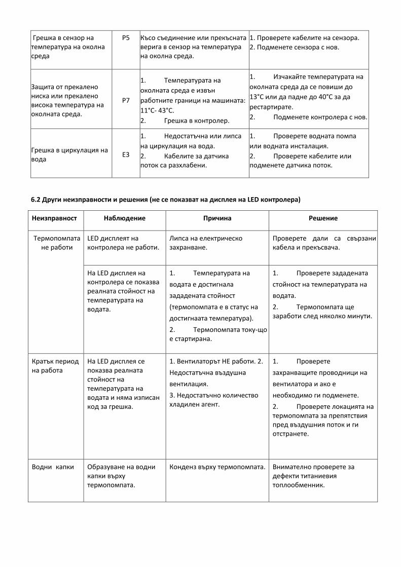
6.2 Други неизправности и решения (не се показват на дисплея на LED контролера)
Неизправност Наблюдение Причина Решение
Термопомпата не работи
LED дисплеят на контролера не работи.
Липса на електрическо захранване.
Проверете дали са свързани кабела и прекъсвача.
На LED дисплея на контролера се показва реалната стойност на температурата на водата.
1. Температурата на
водата е достигнала
зададената стойност
(термопомпата е в статус на
достигнаата температура).
2. Термопомпата току-що е стартирана.
1. Проверете зададената
стойност на температурата на
водата.
2. Термопомпата ще заработи след няколко минути.
Кратък период на работа
На LED дисплея се показва реалната стойност на температурата на водата и няма изписан код за грешка.
1. Вентилаторът НЕ работи. 2.
Недостатъчна въздушна
вентилация.
3. Недостатъчно количество хладилен агент.
1. Проверете
захранващите проводници на
вентилатора и ако е
необходимо ги подменете.
2. Проверете локацията на термопомпата за препятствия пред въздушния поток и ги отстранете.
Водни капки Образуване на водни капки върху термопомпата.
Конденз върху термопомпата. Внимателно проверете за дефекти титаниевия топлообменник.
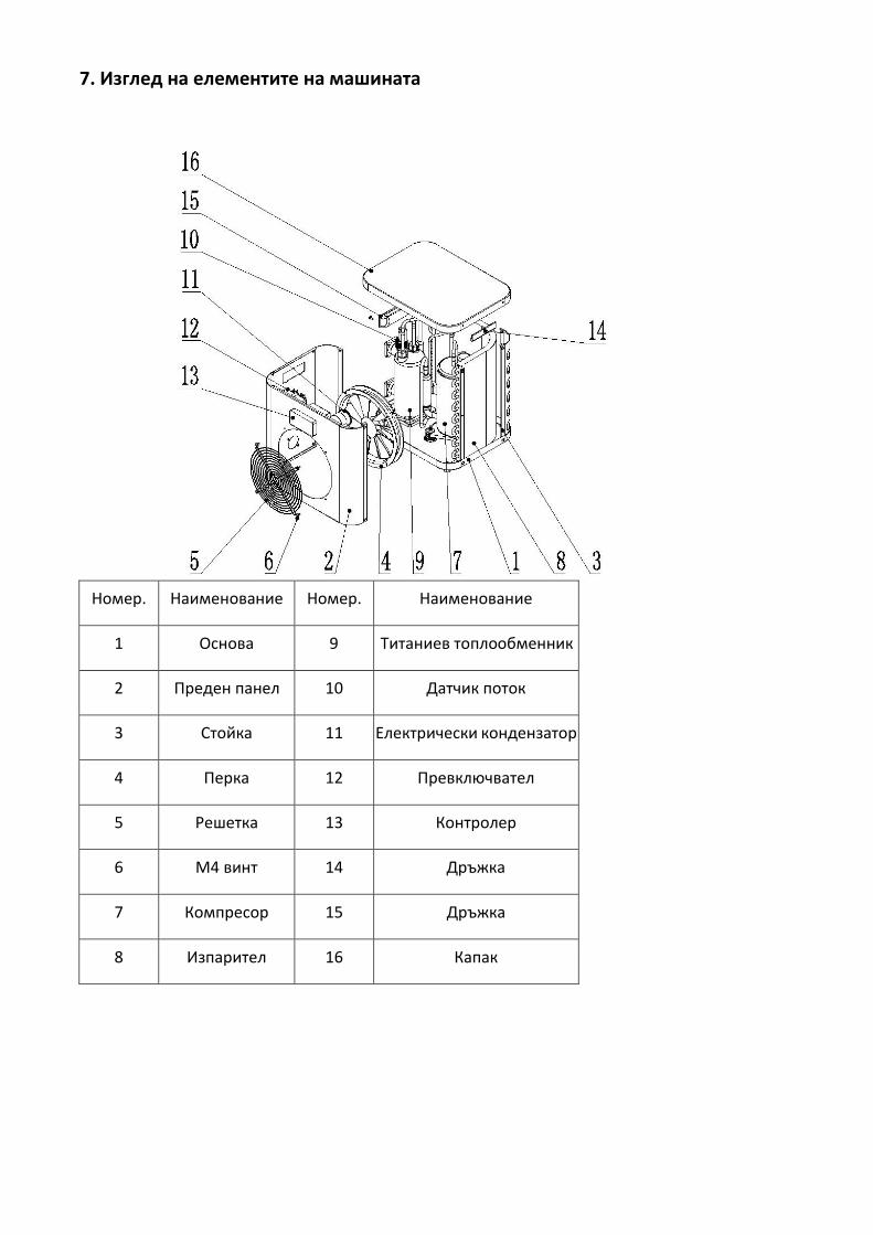
7. Изглед на елементите на машината
Номер. Наименование Номер. Наименование
1 Основа 9 Титаниев топлообменник
2 Преден панел 10 Датчик поток
3 Стойка 11 Електрически кондензатор
4 Перка 12 Превключвател
5 Решетка 13 Контролер
6 M4 винт 14 Дръжка
7 Компресор 15 Дръжка
8 Изпарител 16 Капак
8. Поддръжка
(1) Трябва редовно да проверявате водната инсталация за попаднал в нея въздух и нисък воден дебит,
което може да редуцира производителността и надеждността на термопомпата.
(2) Редовно проверявайте басейните и филтриращата система за да избегнете риска от повреда на
машината поради замърсен или запушен филтър.
(3) Ако термопомпата няма да работи за дълъг период от време, водата в нея трябва да бъде източена
(особено през зимния сезон).
(4) Преди да стартирате отново термопомпата, трябва да проверите дали в нея има вода.
(5) По време на работа на термопомпата под нея е възможно да има малки количества вода (конденз).

Distributor: SILENP
Mail: [email protected]
Web: www.warmpool.eu
Distribuidor: SILENP
Correo: [email protected]
Web: www.warmpool.eu
Дистрибутор: SILENP
Имейл: [email protected]
Уеб: www.warmpool.eu