Embed Size (px)
Citation preview

MINI-LINK HC
Technical Description
MINI-LINK™


MINI-LINK HC
Technical Description

Copyright
© Ericsson AB 2004 – All Rights Reserved
Disclaimer
The contents of this document are subject to revision without notice due to continued progress in methodology, design, and manufacturing.
Ericsson shall have no liability for any error or damage of any kind resulting from the use of this document.

MINI-LINK HC
Technical Description
Contents
1 Introduction 1 1.1 MINI-LINK HC 2 1.2 Applications 3 1.3 Main Features 5 1.4 Related Documents 6
2 System Overview 7 2.1 System Components 7 2.2 Terminal Configurations 12 2.3 Traffic Handling 18 2.4 Transmit Power Control 20 2.5 Network Management 21 2.6 Upgrading 21
3 RAU - Radio Unit 23 3.1 External Interfaces 24 3.2 Functional Description 25 3.3 Functional Blocks 26
4 Antennas 33 4.1 Description 33 4.2 Installation 33
5 MMU - Modem Unit 37 5.1 Front Panel Interfaces 38 5.2 Functional Description 39 5.3 Functional Blocks 40
6 TRU - Traffic Unit 45 6.1 Front Panel Interfaces 46 6.2 Functional Description 47 6.3 Functional Blocks 52

7 AMM - Access Module Magazine 55 7.1 Functional Description 56
8 Auxiliary Units 59 8.1 Fan Unit 59 8.2 DC Distribution Unit 60 8.3 Terminal Server 62
9 Management System 63 9.1 Overview 63 9.2 Terminal Management 64 9.3 Data Communication Network (DCN) 67 9.4 Management Tools 68 9.5 Management Facilities 69 9.6 Configuration Management 70 9.7 Fault Management 72 9.8 Performance Management 75 9.9 Security 77
Glossary 79
Index 83

Introduction
1555-HRA 901 01/1 Rev A 2004-06-02 1
1 Introduction
The MINI-LINK HC product family is used for point-to-point microwave transmission at 155 Mbit/s.
The purpose of this document is to support the reader with detailed information on the MINI-LINK HC products and accessories, from technical and functional points of view.
For ordering information refer to the latest revision of the Product Catalog, see section 1.4.
You may also contact your Ericsson representative or the business manager for your country at:
Ericsson AB Transmission & Transport Networks SE-431 84 Mölndal Sweden
Telephone: +46 31 747 00 00 Fax: +46 31 27 72 25
If there is any conflict between this document and compliance statement, the latter will supersede this document.

Introduction
2 1555-HRA 901 01/1 Rev A 2004-06-02
1.1 MINI-LINK HC
MINI-LINK HC is a compact microwave radio link for voice and data transmission and represents a new generation of synchronous radio for short-haul point-to-point applications, typically in urban areas.
The radio system is able to transmit and receive data at 155 Mbit/s, and supports the SDH STM-1 electrical and optical standards as well as the SONET OC-3 standard (optical).
The terminal can be configured as unprotected (1+0) or protected (1+1).
5544 Figure 1-1. An example of a terminal
MINI-LINK HC microwave radio is a part of Ericsson’s large and extensive product portfolio for telecommunications. The combined expertise of Ericsson, covering switching, cellular technology, radio and networking provides excellent turnkey project management.
A MINI-LINK microwave system integrates fully with existing telecom networks, adding new levels of flexibility. It has proved to be a reliable communication medium, a highly competitive alternative to fiber cable.

Introduction
1555-HRA 901 01/1 Rev A 2004-06-02 3
1.2 Applications
The MINI-LINK HC system can be used in numerous applications, where quality and speed are key characteristics. It provides a high level of redundancy as it can be configured as a protected path (1+1), deployed in a ring structure or as protection for fiber.
Below follow some examples of typical applications.
1.2.1 Mobile Networks
The mobile transmission network can be divided in two parts: core and access networks. Microwave radio is by far the most preferred solution for transmission in access networks, providing reliability, cost efficiency and fast network rollout.
Ericsson defines the access network in two parts, Low Capacity Radio Access Transmission Network (LRAN) and High Capacity Radio Access Transmission Network (HRAN). The LRAN includes the “last mile” access to the base station sites and HRAN consists of high capacity hubs connected to a switch site. MINI-LINK HC systems are well adapted for transmission in HRAN, where transmission rates of 155 Mbit/s and higher are required.
5058
Switch site
Transmission hub site
Core Network
High Capacity RadioAccess TransmissionNetwork (HRAN)
Low Capacity RadioAccess Transmission Network (LRAN)
MSC/MG
MSC/MG
BSC/RNC
HUB
HUBHUB
MSC - Mobile Switching CenterMG - Media Gateway
BSC - Base Station ControllerRNC - Radio Node Controller
Figure 1-2. Core and access networks

Introduction
4 1555-HRA 901 01/1 Rev A 2004-06-02
1.2.2 Business Access Networks
In business access networks, a MINI-LINK point-to-multipoint system can be used to collect traffic from an access point to a central hub. The access points are typically located at small and medium sized enterprises that require high-speed IP applications and voice services. The MINI-LINK HC system can be used to provide connectivity between the hub site of a point-to-multipoint system to a central office where IP and voice services are produced.
5059
Point-to-point hop
Point-to-multipoint system
Figure 1-3. Business access network
Introduction
1555-HRA 901 01/1 Rev A 2004-06-02 5
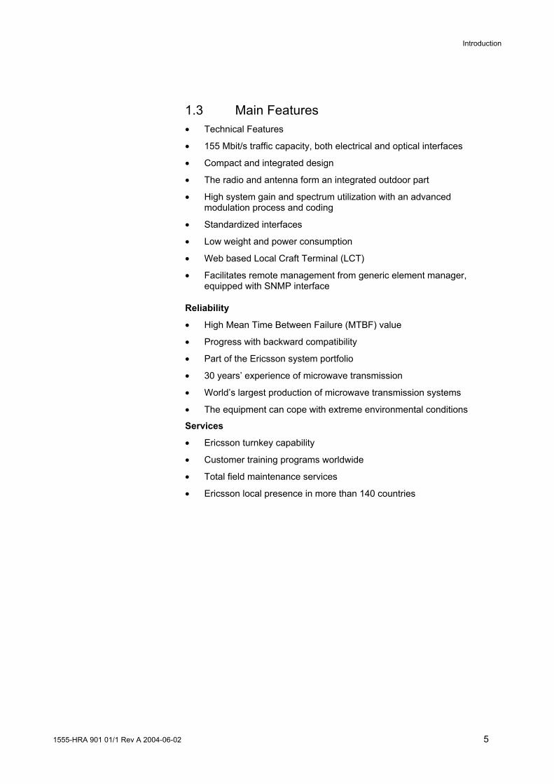
1.3 Main Features • Technical Features
• 155 Mbit/s traffic capacity, both electrical and optical interfaces
• Compact and integrated design
• The radio and antenna form an integrated outdoor part
• High system gain and spectrum utilization with an advanced modulation process and coding
• Standardized interfaces
• Low weight and power consumption
• Web based Local Craft Terminal (LCT)
• Facilitates remote management from generic element manager, equipped with SNMP interface
Reliability
• High Mean Time Between Failure (MTBF) value
• Progress with backward compatibility
• Part of the Ericsson system portfolio
• 30 years’ experience of microwave transmission
• World’s largest production of microwave transmission systems
• The equipment can cope with extreme environmental conditions
Services
• Ericsson turnkey capability
• Customer training programs worldwide
• Total field maintenance services
• Ericsson local presence in more than 140 countries
Introduction
6 1555-HRA 901 01/1 Rev A 2004-06-02
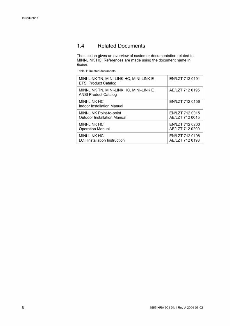
1.4 Related Documents
The section gives an overview of customer documentation related to MINI-LINK HC. References are made using the document name in Italics. Table 1: Related documents
MINI-LINK TN, MINI-LINK HC, MINI-LINK E ETSI Product Catalog
EN/LZT 712 0191
MINI-LINK TN, MINI-LINK HC, MINI-LINK E ANSI Product Catalog
AE/LZT 712 0195
MINI-LINK HC Indoor Installation Manual
EN/LZT 712 0156
MINI-LINK Point-to-point Outdoor Installation Manual
EN/LZT 712 0015AE/LZT 712 0015
MINI-LINK HC Operation Manual
EN/LZT 712 0200AE/LZT 712 0200
MINI-LINK HC LCT Installation Instruction
EN/LZT 712 0198AE/LZT 712 0198

System Overview
1555-HRA 901 01/1 Rev A 2004-06-02 7
2 System Overview
2.1 System Components
5044
TRUMMU
Fan unitAccess ModuleMagazine (AMM)
Radio cable
Radio Unit (RAU)Antenna
Modem UnitTraffic Unit
Figure 2-1. System components
A terminal is one side of a microwave radio link hop, between two geographical locations. The terminal consists of an indoor part and an outdoor part.
The indoor part comprises a Traffic Unit (TRU), Modem Unit (MMU), Access Module Magazine (AMM) and a fan unit. The outdoor part comprises a Radio Unit (RAU) with antenna. A radio cable connects the RAU and the MMU.
Apart from the main units, the system offers a number of well-adapted auxiliary units and accessories, both hardware and software. Refer to the Product Catalog for more information.

System Overview
8 1555-HRA 901 01/1 Rev A 2004-06-02
2.1.1 Indoor Units
4854 Figure 2-2. DDU and fan unit, MMU and TRU in an AMM 2U-4, fitted in a 19” rack
The indoor units of a terminal are briefly described below.
Modem Unit (MMU) The MMU is the indoor interface with the radio unit and contains a modulator/demodulator. One MMU per radio unit is required.
Traffic Unit (TRU) The TRU generates and terminates the STM-1/OC-3 traffic signal. It also contains a protection switching function used for protected terminal configurations. At least one TRU per terminal is required.
Access Module Magazine (AMM) The AMM houses the MMU(s) and TRU(s) and provides electrical interconnection through its backplane. It fits in 19" racks and cabinets, as well as in ETSI and BYB cabinets. One or two terminals can be integrated into one common AMM.
Fan Unit A fan unit is always fitted on top of the AMM to guarantee sufficient cooling. The cooling air enters at the front of the AMM, flows between the units and out through openings at the back of the magazine on both sides of the backplane.
DC Distribution Unit (DDU) (optional) The optional DC Distribution Unit (DDU) can be used to distribute primary power to the MMU(s) and fan unit.

System Overview
1555-HRA 901 01/1 Rev A 2004-06-02 9
Ethernet and E1 Interfaces The MINI-LINK HC terminals can be configured to support a combination of Ethernet and E1 traffic over a link or network, typically used for high speed LAN-to-LAN interconnection and connection of PBXs. The solution provides 4x10BaseT/100BaseTX LAN and 4xE1, G.703 interfaces.

System Overview
10 1555-HRA 901 01/1 Rev A 2004-06-02
2.1.2 Outdoor Units
15 GH
z
15 G
Hz
RADIO
ALARM
POWER
5543 Figure 2-3. RAUs with integrated antenna
The outdoor units of a terminal are briefly described below.
Radio Unit (RAU) The RAU generates and receives the RF signal and converts it to/from the signal format used in the radio cable.
Antenna The compact antenna combines high performance with minimum outdoor visibility. The antenna is normally installed integrated with the antenna but a separate installation is also possible.
Radio Cable The radio cable, which connects the RAU to the MMU, is a single coaxial cable carrying full duplex traffic, DC supply voltage and service traffic as well as operation and maintenance data.
Power Splitter The power splitter is used in 1+1 systems connecting two radio units to one antenna. The power splitter is available in a symmetrical and in an asymmetrical version. An integrated power splitter is also available.

System Overview
1555-HRA 901 01/1 Rev A 2004-06-02 11
2.1.3 Installation
The indoor units can be installed in 19" racks and cabinets, as well as in ETSI and BYB cabinets. DC power supply is connected to the MMU and fan unit directly from an external source or by using a DDU. The TRU is supplied with power by the MMU via the backplane of the AMM. All external connections are made at the unit fronts.
The RAU and the antenna are easily installed on a wide range of support structures. The RAU is fitted directly to the antenna as standard, but can also be installed separately and connected by a flexible waveguide. In both cases, the antenna is easily aligned and the RAU can be disconnected and replaced without affecting the antenna alignment.
The interconnection between the outdoor part and the indoor part is the radio cable carrying full duplex traffic, DC supply voltage, service traffic as well as operation and maintenance data.
Figure 2-4. Outdoor installation
1. Separate installation
2. Integrated installation

System Overview
12 1555-HRA 901 01/1 Rev A 2004-06-02
2.2 Terminal Configurations
The terminal can be configured as unprotected (1+0) or protected (1+1).
The configuration parameters for the equipment are stored in a non-volatile memory in the TRU.
2.2.1 Unprotected Terminal 1+0
TRUMMU
AMM 1U-1
4633
155 Mbit/s
Figure 2-5. 1+0 terminal in an AMM 1U-1
An unprotected terminal 1+0 consists of:
• One RAU
• One antenna
• One AMM (AMM 1U-1 or AMM 2U-4)
• One MMU
• One TRU
• One radio cable for interconnection
Both the AMM 1U-1 and the AMM 2U-4 can be used. When the AMM 2U-4 is used, one or two 1+0 terminals can be installed.
AMM 2U-4
4634
155 Mbit/sTRUMMU
Figure 2-6. 1+0 terminal in an AMM 2U-4

System Overview
1555-HRA 901 01/1 Rev A 2004-06-02 13
MMU
4638
155 Mbit/sTRU
TRU
MMU
155 Mbit/s
AMM 2U-4
Figure 2-7. Two 1+0 terminals, 2×(1+0), in an AMM 2U-4
An AMM 2U-4 with two unprotected terminals, 2×(1+0), can be utilized when there is a need for doubling the traffic capacity in one direction, a common AMM for traffic in different directions or a repeater site.

System Overview
14 1555-HRA 901 01/1 Rev A 2004-06-02
2.2.2 Protected Terminal 1+1
MMU
4635
155 Mbit/sTRUMMU
AMM 2U-4
Figure 2-8. Protected terminal 1+1 in an AMM 2U-4
A protected terminal 1+1 consists of:
• Two RAUs and one of the following:
− Two antennas
− One antenna with one power splitter and two waveguides
− One antenna with one integrated power splitter (RAU2 L)
− One antenna with one integrated power splitter and one waveguide (RAU1 L)
• One AMM 2U-4
• Two MMUs
• One TRU
• Two radio cables for interconnection
Protected configuration should be considered for traffic requiring high availability, but also in case of severe reflections or harsh atmospheric conditions.
It is possible to remove and insert the non-active MMU or RAU without loss of traffic.
A protected 1+1 terminal can be configured for hot standby or working standby.
System Overview
1555-HRA 901 01/1 Rev A 2004-06-02 15
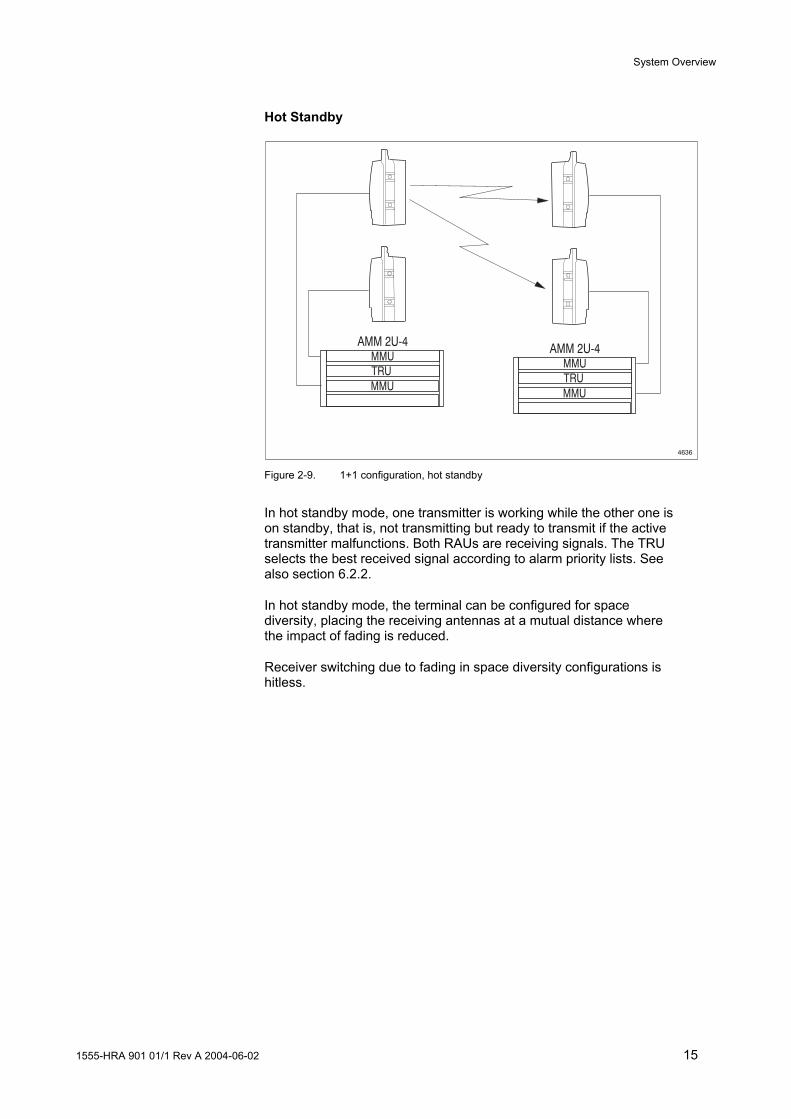
Hot Standby
4636
MMU
AMM 2U-4
TRUMMU
MMU
AMM 2U-4
TRUMMU
Figure 2-9. 1+1 configuration, hot standby
In hot standby mode, one transmitter is working while the other one is on standby, that is, not transmitting but ready to transmit if the active transmitter malfunctions. Both RAUs are receiving signals. The TRU selects the best received signal according to alarm priority lists. See also section 6.2.2.
In hot standby mode, the terminal can be configured for space diversity, placing the receiving antennas at a mutual distance where the impact of fading is reduced.
Receiver switching due to fading in space diversity configurations is hitless.
System Overview
16 1555-HRA 901 01/1 Rev A 2004-06-02
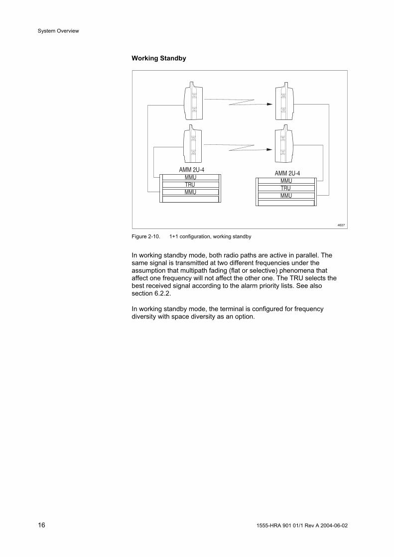
Working Standby
4637
MMU
AMM 2U-4
TRUMMU
MMU
AMM 2U-4
TRUMMU
Figure 2-10. 1+1 configuration, working standby
In working standby mode, both radio paths are active in parallel. The same signal is transmitted at two different frequencies under the assumption that multipath fading (flat or selective) phenomena that affect one frequency will not affect the other one. The TRU selects the best received signal according to the alarm priority lists. See also section 6.2.2.
In working standby mode, the terminal is configured for frequency diversity with space diversity as an option.

System Overview
1555-HRA 901 01/1 Rev A 2004-06-02 17
2.2.3 ELP
6644
MMU
AMM 2U-4
TRUMMU
MMU
AMM 2U-4
TRUMMU
TRUTRU
ADM ADM
Figure 2-11. 1+1 configuration, ELP
The Equipment and Line Protection (ELP) functionality is able to simultaneously protect the STM-1/OC-3 line interface and the radio equipment against any single point of failure (e.g. the single TRU). On the radio side, it uses a single frequency (hot standby configuration).
In this mode the radio section performs protection switching on the transmitter side. Receiver switching in the TRU is disabled. The ADMs at both ends carry out the receiver protection switching.

System Overview
18 1555-HRA 901 01/1 Rev A 2004-06-02
2.3 Traffic Handling
The system is able to transmit and receive data at 155 Mbit/s, and supports the SDH STM-1 electrical and optical standards as well as the SONET OC-3 standard (optical).
The following channels are physically connected at the TRU front for further transportation over the hop:
• Main Traffic (155 Mbit/s) SDH STM-1 electrical and optical standards or SONET OC-3 standard Implemented in the payload of the SDH/SONET frame and handled by the TRU.
• Wayside Traffic (1.5/2 Mbit/s) Implemented in RFCOH and handled by the MMU.
• Service Channel V.11 (64 kbit/s) Implemented in RSOH in the SDH/SONET frame and handled by the TRU.
• Service Channel G.703 (64 kbit/s) Implemented in RSOH in the SDH/SONET frame and handled by the TRU
Wayside Traffic
Service Channel64 kbit/s V.11
Service Channel64 kbit/s G.703
Main Traffic155 Mbit/s
TRU MMU
RAU
1.5/2 Mbit/s
5060
SDH STM-1SONET OC-3
SDH/SONETFrame
SDH/SONETFrame + RFCOH
Figure 2-12. Traffic paths in an unprotected terminal

System Overview
1555-HRA 901 01/1 Rev A 2004-06-02 19
2.3.1 SDH/SONET Frame
The structure of the SDH/SONET frame is shown in the figure below.
4665
1-9 10-274
1-3
4
5-9 MSOH
AU PointersPayload
RSOH
+RFCOH
4665 Figure 2-13. The SDH/SONET frame
Regenerator Section Overhead Frame (RSOH)
The following bytes in the RSOH in the SDH/SONET frame are used for service channels and internal communication channels.
1 2 3 4 5 6 7 8 9
1 A1 A1 A1 A2 A2 A2 J0/C1 NU NU 2 B1 EOC EOC E1 FU F1 NU NU 3 D1 ATPC EOC D2 FU D3 FU FU 4 AU pointers 5 B2 B2 B2 K1 K2 6 D4 D5 D6 7 D7 D8 D9 8 D10 D11 D12 9 S1 Z1 Z1 Z2 Z2 M1 E2 NU NU
RSOH Byte Channel E1* Service Channel G.703/V.11 (64 kbit/s) F1* Service Channel G.703/V.11 (64 kbit/s) ATPC ATPC feedback channel EOC Embedded Operation and Maintenance Channel (192
kbit/s) D1-D3 DCC Data Communication Channel (192 kbit/s)
NU Byte available for national use FU Reserved for future use
* The RSOH bytes for the service channels are software selectable.

System Overview
20 1555-HRA 901 01/1 Rev A 2004-06-02
2.4 Transmit Power Control
The radio output power can be controlled in fixed or adaptive mode.
4678
Outputpower
P
fix min
max
adapt. min
set
Equipmentlimits
Fixed mode Adaptive mode
P
P
P
setP
outP
outP
Figure 2-14. Transmit power control
2.4.1 Fixed Mode
In fixed mode the output power Pout ranges from a minimum level Pfix min to a maximum level Pmax.
A value Pset is manually set, in 1 dB increments, locally or remotely from the management system.
2.4.2 Adaptive Mode
In adaptive mode the Automatic Transmit Power Control (ATPC) function is used to automatically control the output power Pout. The output power is continuously adjusted in order to maintain a minimum input level (set from the LCT) at the far-end terminal. The ATPC function varies the output power, between a selected maximum level Pset and a minimum level Padapt min.
The receiver input level at the far-end and the maximum transmitter power level Pset are set, locally and remotely from the management system.
Under normal path conditions the ATPC maintains the output power at a reduced level resulting in a lower interference level in the radio network.

System Overview
1555-HRA 901 01/1 Rev A 2004-06-02 21
2.5 Network Management
Each terminal is equipped with an embedded web server providing all standard management functions. Local management at site is done from a Local Craft Terminal (LCT), by accessing the web server from a web browser on a PC connected to the terminal.
Remote management from MINI-LINK Manager allows display of network status and configuration. A web based interface, similar to the one in the LCT, can be launched enabling certain configuration facilities.
Remote management can also be accomplished from any Network Management System (NMS) using SNMPv1 or v3 for the communication.
The terminal has an internal TCP/IP stack which enables insertion in an IP based DCN.
2.6 Upgrading
The MINI-LINK HC terminal is a flexible system where both hardware and software can be upgraded and reconfigured, providing site flexibility. Below follow some examples:
• An unprotected terminal can be converted to a protected or dual terminal with addition of required hardware.
• Exchanging an MMU 155/16 for an MMU 155/128 results in reduced air interface bandwidth.
• When a site configuration requires an optical traffic interface it is possible to exchange a TRU EL. for a TRU OPT./EL..
• When the system is to be upgraded with a new software revision, a download is performed to the non-volatile memory in the TRU. The change to the new revision is then handled from the LCT.

System Overview
22 1555-HRA 901 01/1 Rev A 2004-06-02

RAU - Radio Unit
1555-HRA 901 01/1 Rev A 2004-06-02 23
3 RAU - Radio Unit
RADIO
ALARM
POWER
6757 Figure 3-1. RAU1 and RAU2 mechanical design
The basic function of the Radio Unit (RAU) is to generate and receive the RF signal and convert it to/from the signal format in the radio cable, connecting the RAU and the MMU. The RAU is available with two types of mechanical design, RAU1 and RAU2.
The RAUs dedicated for MINI-LINK HC are designated RAU1 L and RAU2 L. An RAU of type RAU1 N and RAU2 N provides the same functionality, when used in a MINI-LINK HC system.
The RAU can be combined with a wide range of antennas in integrated or separate installation.
The RAU is a weatherproof box painted light gray, with a handle for lifting and hoisting. There are also two hooks and catches to guide it for easier handling, when fitting to or removing from an integrated antenna.
It comprises a cover, vertical frame, microwave sub-unit, control circuit board and filter unit. The microwave sub-unit consists of a microstrip board with an aluminum cover that provides shielded compartments for the high-frequency circuits. The control circuit board, which holds the control and supervision processor, is fitted at the back of the microstrip board.
The RAU connects to the antenna at the waveguide interface. Disconnection and replacement of the RAU can be done without affecting the antenna alignment.
DC power to the RAU is supplied from the MMU through the radio cable.

RAU - Radio Unit
24 1555-HRA 901 01/1 Rev A 2004-06-02
3.1 External Interfaces
RADIOALARM
POWERALIGNMENT
RADIO CABLE
5353
4
4 21 3
1 2 3
Figure 3-2. RAU1 L and RAU2 L external interfaces
All connections to and from the RAU are made at the rear.
Radio Cable
1. Radio cable connection to the MMU, 50 Ω N-type connector. The connector is equipped with gas discharge tubes for lightning protection
Grounding
2. Protective ground point to connect to mast ground
ALIGNMENT
3. Test port for antenna alignment
LED Indicators
4. Two LED Indicators:
• Red light: Unit alarm
• Green light: Power on
Waveguide Interface
The vertical frame has a waveguide interface for connection to the antenna (placed on the front side, not shown on the illustration above).

RAU - Radio Unit
1555-HRA 901 01/1 Rev A 2004-06-02 25
3.2 Functional Description
3.2.1 Transmitting Frequency
The channel frequency of a terminal is determined entirely by the RAU, which are available for different frequency channels and sub-bands.
The two RAUs needed for a hop are matched in pairs. Each of the radio units covers a sub-band of the frequency band and has a fixed duplex distance, the difference between the transmitted and the received frequency.
The transmitting frequency is set on site using the LCT. Increments of 0.25 MHz within a sub-band are possible.
For detailed information on frequency plans, see the Product Catalog.
4655
TX
RX
RX
TX
Transmit frequency terminal A
Transmit frequency terminal B
Sub band
Frequency bandF
Sub band
Duplex distance
Figure 3-3. The two RAUs in a hop are operating at different sub-bands within a frequency
band
RAU - Radio Unit
26 1555-HRA 901 01/1 Rev A 2004-06-02
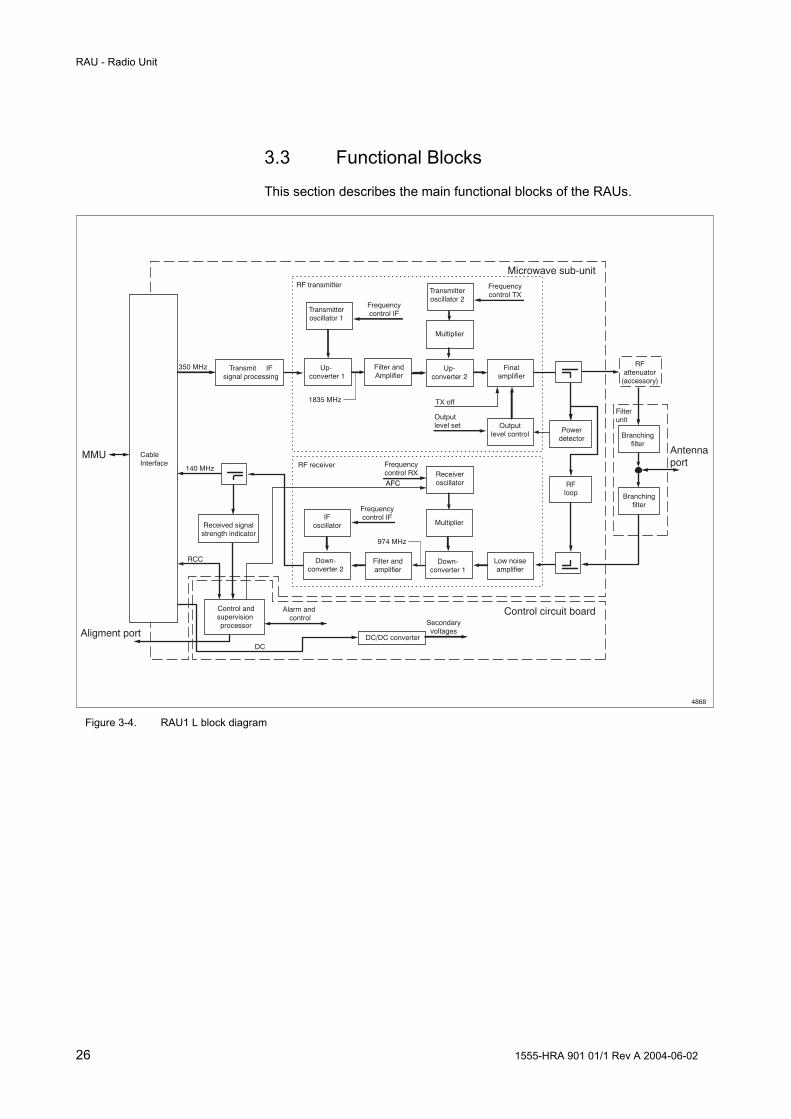
3.3 Functional Blocks
This section describes the main functional blocks of the RAUs.
Aligment port DC/DC converter
Control andsupervision processor
Up-converter 2
Finalamplifier
Outputlevel control Power
detector
Transmit IFsignal processing
Branchingfilter
Branchingfilter
Alarm and control
Down-converter 1
Multiplier
Low noiseamplifier
Frequencycontrol RX
RFattenuator
(accessory)
Microwave sub-unitRF transmitter
MMU CableInterface
Received signalstrength indicator
RF receiver
RFloop
Secondaryvoltages
TX off
Outputlevel set
Filterunit
Down-converter 2
Filter andamplifier
Up- converter 1
Filter andAmplifier
Transmitteroscillator 1
Frequencycontrol IF
IFoscillator
Frequencycontrol IF
ReceiveroscillatorAFC
Antennaport
DC
140 MHz
RCC
350 MHz
1835 MHz
974 MHz
4868
Transmitteroscillator 2
Frequencycontrol TX
Multiplier
Control circuit board
Figure 3-4. RAU1 L block diagram

RAU - Radio Unit
1555-HRA 901 01/1 Rev A 2004-06-02 27
Aligment port DC/DC converter
Control andsupervision processor
Up-converter 2
Finalamplifier
Outputlevel control Power
detector
Transmitteroscillator 2
Transmit IFsignal processing
Alarm and control
Down-converter 1
Multiplier
Low noiseamplifier
Frequencycontrol RX
Microwave sub-unit
Frequencycontrol TX
RF transmitter
MMU CableInterface
Received signalstrength indicator
RF receiver
Secondaryvoltages
TX off
Outputlevel set
Down-converter 2
Filter andamplifier
Up- converter 1
Filter andAmplifier
Transmitteroscillator 1
Frequencycontrol IF
IFoscillator
Frequencycontrol IF
ReceiveroscillatorAFC
DC
140 MHz
RCC
350 MHz
1835 MHz
974 MHz
5514
Multiplier
Control circuit board
Branchingfilter
Filterunit
Antennaport
Branchingfilter
RFLoop
Figure 3-5. RAU2 L block diagram

RAU - Radio Unit
28 1555-HRA 901 01/1 Rev A 2004-06-02
3.3.1 Cable Interface
The incoming composite signals and supply from the indoor units are demultiplexed in the cable interface and forwarded for further processing in the RAU. The signals are:
• The transmit IF signal, a modulated signal with a nominal frequency of 350 MHz
• The up-link for command and control signal, the Radio Communication Channel (RCC), an ASK (Amplitude Shift Keying) modulated signal with a nominal frequency of 6.5 MHz
• The DC supply voltage to the RAU
Similarly, the outgoing signals from the RAU are multiplexed in the cable interface:
• Receive IF signal, which has a nominal frequency of 140 MHz
• The down-link (RCC), an ASK modulated signal with a nominal frequency of 4.5 MHz
In addition to the above, the cable interface includes an over voltage protection circuit.
3.3.2 DC/DC Converter
The DC/DC converter provides stable secondary voltages for the RAU.
3.3.3 Control and Supervision Processor
The microwave sub-unit houses the Slave Processor (SP) for control and supervision of the RAU with main functions as described below.
Alarm Collection Collected alarms and status signals from the RAU are sent to the indoor MMU processor. Summary status signals are visualized by LEDs on the RAU.
Command Handling Commands from the indoor units are executed. These commands include transmitter activation/deactivation, channel frequency settings, output power settings and RF loop activation/deactivation.
RAU Control and Message Handling In addition to the above, the processor controls the unit’s internal processes and loops.

RAU - Radio Unit
1555-HRA 901 01/1 Rev A 2004-06-02 29
3.3.4 Transmit IF Signal Processing
The input amplifier is automatically gain-controlled so no compensation is required for the cable length between indoor and outdoor equipment. The level is used to generate an alarm, indicating that the transmit IF signal level is too low due to excessive cable losses.
3.3.5 Transmitter Blocks
The signal to be transmitted is amplified and up-converted from 350 MHz up to the transmit frequency in two steps.
Amplifier and Up-converter 1 The transmit IF signal is up-converted to a second transmit IF of 1835 MHz.
Filter and Amplifier The up-converted signal is bandpass filtered and amplified.
Transmitter Oscillator 1 The frequency of the transmitter is controlled in a Phase Locked Loop (PLL). A sample of the Voltage-controlled Oscillator (VCO) signal is fed to a divider and further on to a programmable phase detector. The error signal is controlled by the integrated control and supervision system by using a serial bus. An unlocked VCO generates the transmitter frequency alarm.
Up-converter 2 The transmit IF signal is amplified and up-converted to selected radio transmit frequency.
Transmitter Oscillator 2 and Multiplier Oscillator 2 is implemented in the same way as oscillator 1. The signal is then multiplied (2 or 4 times depending on channel frequency) and amplified.
Final Amplifier Adjusting the gain of the final amplifier controls the transmitter output power, and is set in increments of 1 dB from the LCT. The transmitter can be switched on or off, through the final amplifier.
Power Detector and Output Level Control A sample of the transmit signal is used for supervision of the transmitted power (output power alarm). The measured power level is also used as feedback to the output level control, which adjusts the final amplifier.

RAU - Radio Unit
30 1555-HRA 901 01/1 Rev A 2004-06-02
3.3.6 RF Loop
The RF Loop is used for test purposes only. In RAU1 L a sample of the transmission signal is mixed with a shift oscillator signal and fed into the receiver. For RAU2 L the loop is set when the transmitter frequency is changed to receiver frequency and transferred to the receiving side.
3.3.7 RF Attenuator
In addition to the transmitter output level control, the RF level for RAU1 L may be further decreased by fitting a fixed RF attenuator to the microwave sub-unit. The output level for RAU2 L can be varied in its whole range without any fixed attenuators.
3.3.8 Branching Filter
On the transmitting side, the signal is fed to the antenna through an output branching filter. The signal from the antenna is fed to the receiving side through an input branching filter. The antenna and both branching filters are connected with an impedance T-junction.
3.3.9 Receiver Blocks
The received signal is amplified and down-converted in two steps into a 140 MHz IF signal. A portion of this 140 MHz is used in the Received Signal Strength Indicator (RSSI). The 140 MHz signal from the IF Converter is amplified and fed to the cable interface. This double superheterodyne receiver with a high first IF enables frequency selection over a wide frequency band, with excellent receiver spurious and image rejection.
Low Noise Amplifier The received signal is fed from the input branching filter into a low noise amplifier.
Down-converter 1 The first down-converter gives the IF of 974 MHz
Receiver Oscillator and Multiplier The local oscillator signal used in the first down-conversion is generated in the same way as for the Transmitter Oscillator. The signal is multiplied (2 or 4 times depending on channel frequency) and amplified.
Amplifier and Filter The down-converted signal is amplified and bandpass filtered.
Down-converter 2 The signal is down-converted a second time to the IF of 140 MHz (IF Converter)

RAU - Radio Unit
1555-HRA 901 01/1 Rev A 2004-06-02 31
IF Oscillator The oscillator consists of a PLL and a VCO. It is used for the second down-conversion to 140 MHz. The VCO is also used for adjustment of the received 140 MHz signal (through a control signal setting the division number in the IF PLL). A frequency error signal from the MMU is used to shift the receiver oscillator in order to facilitate an Automatic Frequency Control (AFC) loop.
Received Signal Strength Indicator (RSSI) A portion of the 140 MHz signal is fed to a calibrated detector in the RSSI to provide an accurate receiver input level measurement. The measured level is accessible either as an analog voltage at the alignment port or in dBm from the LCT.
The RSSI signal is also used for adjustment of the output power by means of the Automatic Transmit Power Control (ATPC).

RAU - Radio Unit
32 1555-HRA 901 01/1 Rev A 2004-06-02

Antennas
1555-HRA 901 01/1 Rev A 2004-06-02 33
4 Antennas
4.1 Description
The antennas range from 0.2 m (9”) up to 3.7 (12 ft) in diameter, in single and dual polarized versions. All antennas are "compact", that is the design is compact with a low profile.
Antennas up to 1.8 m (6 ft) in diameter can be fitted integrated with the radio unit and all antennas can be installed separately if required. For detailed information on available antennas, see the Product Catalog.
The antennas are made of aluminum and painted light gray. All antennas have a standard IEC 154 type B waveguide interface that can be adjusted for vertical or horizontal polarization.
All high performance antennas have an integrated radome.
4.2 Installation
4.2.1 Integrated Installation
The radio unit is fitted directly to the rear of the antenna in integrated installation for a 1+0 configuration.
15 G
Hz
15 G
Hz
RADIO
ALARM
POWER
15 G
Hz
RADIO
ALARM
POWER
15 G
Hz
15 G
Hz
RADIO
ALARM
POWER
6761 Figure 4-1. 0.2 m, 0.3 m and 0.6 m compact antennas integrated with RAU2 L

Antennas
34 1555-HRA 901 01/1 Rev A 2004-06-02
6758
RADIO
ALARM
POWERRADIO CABLE
AGC
RADIO
ALARM
POWERRADIO CABLE
AGC
Figure 4-2. 0.3 m and 0.6 m compact antennas integrated with RAU1 L
For a 1+1 configuration the RAU2 L can be fitted directly to an integrated power splitter. A similar solution is available for RAU1 L, using a waveguide between the power splitter and the antenna.
The integrated power splitter is normally symmetrical, with equal attenuation in both channels.
6144
15
GH
z
15 G
Hz
ALIGNMENT
RADIOCABLE
RADIOALARM
POWER
Figure 4-3. Two RAU2 L radio units fitted to an integrated power splitter

Antennas
1555-HRA 901 01/1 Rev A 2004-06-02 35
4.2.2 Separate Installation
All antennas with IEC 154 Type B waveguide interface can be installed separately, by using a flexible waveguide to connect to the RAU.
5354 Figure 4-4. Separate installation in a 1+0 configuration
In case of a protected terminal, the two radio units can be connected to a common antenna. In a separate installation the radio units are connected by waveguides to a power splitter, fitted to the antenna.
The power splitter is normally symmetrical, with equal attenuation in both channels.
5355 Figure 4-5. Separate installation in a 1+1 configuration

Antennas
36 1555-HRA 901 01/1 Rev A 2004-06-02
4.2.3 Mounting Kits
This section describes the mounting kits used for the 0.2 m, 0.3 m and 0.6 m antennas. A mounting kit consists of two rigid, extruded aluminum brackets connected with two stainless steel screws along the azimuth axis. The brackets are anodized and have threaded and unthreaded holes to provide adjustment of the antenna in azimuth and elevation.
The support can be clamped to poles with a diameter of 50 – 120 mm or on L-profiles 40×40×5 – 80×80×8 mm with two anodized aluminum clamps.
All screws and nuts for connection and adjustment are in stainless steel. NORD-LOCK washers are used to secure the screws.
6759 Figure 4-6. 0.2 m compact antenna mounting kit
The 0.2 m compact antenna mounting kit can be adjusted by ±13° in elevation and by ±90° in azimuth.
6760 Figure 4-7. Mounting kit for 0.3 m and 0.6 m compact antennas
The mounting kit for 0.3 m and 0.6 m compact antenna can be adjusted by ±15° in elevation and ±40° in azimuth. Both elevation and azimuth have a mechanism for fine adjustment.

MMU - Modem Unit
1555-HRA 901 01/1 Rev A 2004-06-02 37
5 MMU - Modem Unit
The main function of the MMU is to modulate the STM-1/OC-3 digital data to an analogue signal suitable for microwave transmission and demodulate the received signal from the RAU.
The MMU is fully independent of frequency of the transmitting radio and provides traffic capacity of 155 Mbit/s along with a 1.5/2 Mbit/s wayside channel.
Two following MMU versions are available:
• MMU 155/16 with 50/55/56/80 MHz of bandwidth (using 16 QAM)
• MMU 155/128 with 27.5/28/40/50 MHz of bandwidth (using 128 QAM)
4647 Figure 5-1. MMU
MMU - Modem Unit
38 1555-HRA 901 01/1 Rev A 2004-06-02
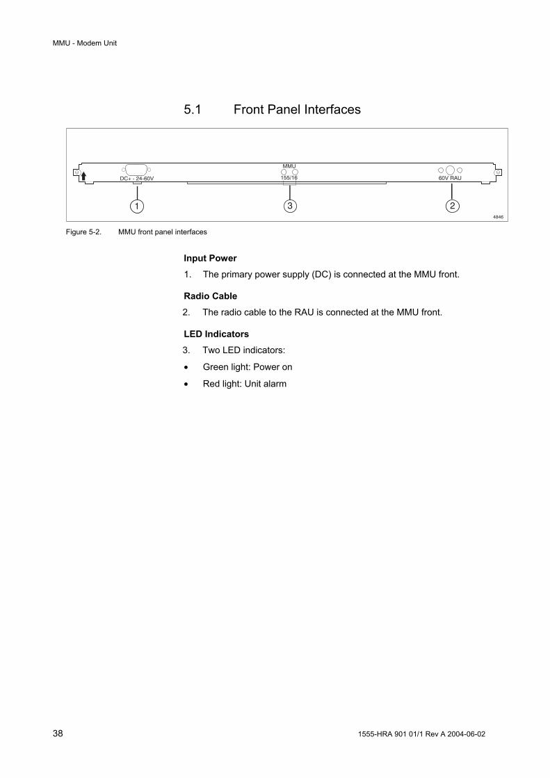
5.1 Front Panel Interfaces
1 231 234846
DC+ - 24-60V
MMU
155/16 60V RAU
Figure 5-2. MMU front panel interfaces
Input Power
1. The primary power supply (DC) is connected at the MMU front.
Radio Cable
2. The radio cable to the RAU is connected at the MMU front.
LED Indicators
3. Two LED indicators:
• Green light: Power on
• Red light: Unit alarm

MMU - Modem Unit
1555-HRA 901 01/1 Rev A 2004-06-02 39
5.2 Functional Description
Wayside Traffic
Service Channel64 kbit/s V.11
Service Channel64 kbit/s G.703
Main Traffic155 Mbit/sSDH STM-1SONET OC-3
TRU MMU
ATPC
RAU
5062
1.5/2 Mbit/s
SDH/SONETFrame + RFCOH
SDH/SONETFrame
Figure 5-3. The MMU handles ATPC and wayside traffic
The MMU inserts the Automatic Transmit Power Control (ATPC) byte into the RSOH.
The MMU adds four extra columns to the SDH/SONET frame and inserts the wayside traffic (1.5/2 Mbit/s) into RFCOH.

MMU - Modem Unit
40 1555-HRA 901 01/1 Rev A 2004-06-02
5.3 Functional Blocks
This section describes the main functional blocks of the MMU.
RFCOHModulator
Cableinterface
Radio unit
Bac
kpla
ne c
onne
ctio
n to
TR
U
Line to radio
RFCOHDemodulator
Radio to line
Control andsupervisionprocessor
ICC RCC
Primarypowersupply
Filtered primaryvoltages
DC/DCconverter RAU DC power supply
Secondaryvoltages
ATPC
ATPC
5063
Wayside traffic 1.5/2 Mbit/s
Wayside traffic 1.5/2 Mbit/s
Main traffic 155 Mbit/s
Main traffic 155 Mbit/s
Figure 5-4. MMU block diagram
5.3.1 RFCOH – Line to Radio
The block handles the addition of RFCOH bytes (four extra columns).
The following data types are merged into one data stream to be transmitted over the radio path:
• Main traffic 155 Mbit/s, STM-1/OC-3
• Wayside traffic 1.5/2 Mbit/s, inserted in RFCOH
• Automatic Transmit Power Control (ATPC) byte, inserted in RSOH

MMU - Modem Unit
1555-HRA 901 01/1 Rev A 2004-06-02 41
4668
1-9 10-274
1-3
4
5-9 MSOH
AU PointersPayload
+RFCOH
RSOH
Figure 5-5. RFCOH adds four extra columns to the SDH/SONET frame
5.3.2 Modulator
The modulator includes the functions below.
Scrambler The scrambler randomizes the digital data stream to break up any repetitive bit patterns before the modulation process.
Forward Error Correction Encoder (FEC) FEC bits are inserted according to a Reed-Solomon encoder. The frame format is formed by 255 bytes.
Interleaver The interleaver spreads the data to be transmitted in the time domain, in order to reduce the effect of burst errors.
QAM Mapper The baseband stream is converted into two parallel binary bitstreams. The mapper generates the symbols for the in-phase and quadrature channels.
Digital Filtering Implements the pulse shaping according to a square root raised cosine filter.
IF Modulator The IF modulator consists of an oscillator operating at 350 MHz. For test purposes an IF loop signal of 140 MHz is also generated. This is accomplished by mixing the 350 MHz signal with a 490 MHz signal.
MMU - Modem Unit
42 1555-HRA 901 01/1 Rev A 2004-06-02
5.3.3 Demodulator
The demodulator shifts the 140 MHz signal to the baseband. The demodulator also includes the functional blocks described below.
Clock Synchronization The data synchronisation is recovered from the incoming traffic signal.
Digital Filtering Completes the shaping of the signal at the receiving side according to a Nyquist filter.
Adaptive Equalization A linear synchronous digital equalizer counteracts the effect caused by selective fading.
Carrier Frequency Error Compensation Compensates for errors in carrier frequency, in order to have a coherent modulation.
QAM Demapper Conversion of the QAM symbol to corresponding bits.
FEC Decoding The FEC function performs the frame alignment and the error correction by means of the Reed-Solomon decoder.
De-interleaver The de-interleaver reassembles the received data in the proper temporal order.
Descrambler The descrambler transforms the signal to its original state enabling the demultiplexer to distribute the received information to its destinations.
5.3.4 RFCOH – Radio to Line
The frame alignment function searches and locks the receiver to the frame alignment bit patterns in the received data stream. The demultiplexer generates a frame fault alarm if frame synchronization is lost.
On the receiver side the MMU demultiplexes the incoming composite data stream into:
• Main traffic 155 Mbit/s, STM-1/OC-3
• Wayside traffic 1.5/2 Mbit/s, extracted from RFCOH
• Automatic Transmit Power Control (ATPC) byte, extracted from RSOH

MMU - Modem Unit
1555-HRA 901 01/1 Rev A 2004-06-02 43
5.3.5 Cable Interface
The following signals are frequency multiplexed in the cable interface for further distribution through the radio cable to the RAU:
• 350 MHz transmit IF signal
• 140 MHz receive IF signal
• DC power supply
• Radio communication channel signal as an ASK (Amplitude Shift Keying) signal
In addition to the above, the cable interface includes an over voltage protection circuit.
5.3.6 Control and Supervision Processor
A control and supervision subsystem is built into the MMU. Its main functions are to collect alarms, control settings and test functions. LEDs on the front of the units are used for alarm indications.
The MMU processor handles the alarm collection and communicates with processors both in the RAU, through the Radio Communication Channel (RCC), and in the TRU, using the Internal Communication Channel (ICC).
5.3.7 DC/DC Converter
The isolated DC/DC converter produces a stable voltage for the RAU and secondary voltages for the MMU electronics.
The filtered primary voltage is distributed to the TRUs through the backplane of the AMM.

MMU - Modem Unit
44 1555-HRA 901 01/1 Rev A 2004-06-02

TRU - Traffic Unit
1555-HRA 901 01/1 Rev A 2004-06-02 45
6 TRU - Traffic Unit
The main function of the TRU is to interface the 155 Mbit/s main traffic, STM-1/OC-3, and transmit it to and receive it from the MMU.
The TRU also provides radio protection switching.
The central processor in the TRU stores operation and maintenance data received from other units in the terminal. This information is retrievable from the external management software.
Two different types of TRU are available:
• TRU EL. with electrical traffic interface
• TRU OPT./EL. with optical and electrical traffic interfaces
6645 Figure 6-1. TRU EL. with electrical interface
6646 Figure 6-2. TRU OPT./EL. with optical and electrical interfaces

TRU - Traffic Unit
46 1555-HRA 901 01/1 Rev A 2004-06-02
6.1 Front Panel Interfaces
1 2 32 1 101 2 37 6 3 2 956211
2 34 8
O & M 64 KB V1110 B
AS
E T
OUT OPT. IN IN EL OUT
TRU
OPT./EL WST FAN 64 KB G703 USER I/O
311
LCT Reset
Figure 6-3. The TRU front panel interfaces
Main Traffic
1. STM-1 (155 Mbit/s) Electrical Interface
2. STM-1/OC-3 (155 Mbit/s) Optical Interface (only TRU OPT./EL.)
Auxiliary Channels
3. G.703 Service Channel (64 kbit/s)
4. V.11 Service Channel (64 kbit/s)
5. Wayside Traffic (1.5/2 Mbit/s)
Operation and Maintenance Interfaces
6. RS 232 for connection of the LCT
7. Ethernet 10/100BaseT for supervision through a Data Communication Network (DCN) or connection of the LCT
8. User I/O ports 12 selectable input/output ports for connection of external user alarms or control of external equipment.
9. Fan Alarm for connection of an alarm cable from the fan unit
LED Indicators
10. Three LED indicators:
• Green light: Power On
• Yellow light: Test Mode
• Red light: Unit Alarm
LCT Reset
11. Pressing the button initiates a warm reboot of the unit. This operation does not disturb traffic.
TRU - Traffic Unit
1555-HRA 901 01/1 Rev A 2004-06-02 47
6.2 Functional Description
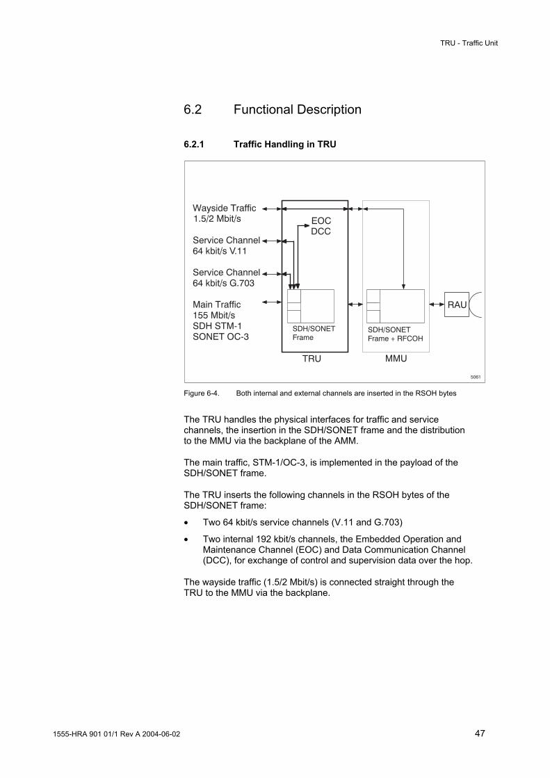
6.2.1 Traffic Handling in TRU
Wayside Traffic
Service Channel64 kbit/s V.11
Service Channel64 kbit/s G.703
Main Traffic155 Mbit/sSDH STM-1SONET OC-3
TRU MMU
EOCDCC
RAU
1.5/2 Mbit/s
5061
SDH/SONETFrame
SDH/SONETFrame + RFCOH
Figure 6-4. Both internal and external channels are inserted in the RSOH bytes
The TRU handles the physical interfaces for traffic and service channels, the insertion in the SDH/SONET frame and the distribution to the MMU via the backplane of the AMM.
The main traffic, STM-1/OC-3, is implemented in the payload of the SDH/SONET frame.
The TRU inserts the following channels in the RSOH bytes of the SDH/SONET frame:
• Two 64 kbit/s service channels (V.11 and G.703)
• Two internal 192 kbit/s channels, the Embedded Operation and Maintenance Channel (EOC) and Data Communication Channel (DCC), for exchange of control and supervision data over the hop.
The wayside traffic (1.5/2 Mbit/s) is connected straight through the TRU to the MMU via the backplane.
TRU - Traffic Unit
48 1555-HRA 901 01/1 Rev A 2004-06-02
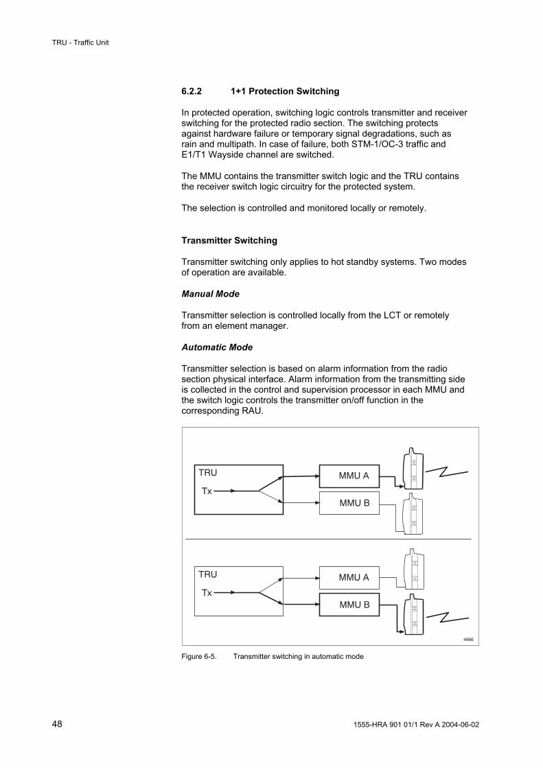
6.2.2 1+1 Protection Switching
In protected operation, switching logic controls transmitter and receiver switching for the protected radio section. The switching protects against hardware failure or temporary signal degradations, such as rain and multipath. In case of failure, both STM-1/OC-3 traffic and E1/T1 Wayside channel are switched.
The MMU contains the transmitter switch logic and the TRU contains the receiver switch logic circuitry for the protected system.
The selection is controlled and monitored locally or remotely.
Transmitter Switching
Transmitter switching only applies to hot standby systems. Two modes of operation are available.
Manual Mode
Transmitter selection is controlled locally from the LCT or remotely from an element manager.
Automatic Mode
Transmitter selection is based on alarm information from the radio section physical interface. Alarm information from the transmitting side is collected in the control and supervision processor in each MMU and the switch logic controls the transmitter on/off function in the corresponding RAU.
4666
TRU
Tx
MMU A
MMU B
TRU
Tx
MMU A
MMU B
Figure 6-5. Transmitter switching in automatic mode

TRU - Traffic Unit
1555-HRA 901 01/1 Rev A 2004-06-02 49
Receiver Switching
Receiver selection applies to both hot standby and working standby systems. Two modes of operation are available.
Manual Mode
It is possible to make the receiver switch to one side locally from the LCT or remotely from an element manager.
Manual switching to one side is not guaranteed to be hitless.
Automatic Mode
Receiver selection is based on alarm information from the receiver section of the RAU or the MMU. Alarm information is collected in the control and supervision processor in each MMU and sent to the switch logic unit in the TRU. An alarm with higher priority overrides an alarm with lower priority. In the event of a failure, the receiver with the lowest alarm priority is selected.
Receiver changeover due to HW failure is not guaranteed to be hitless.
TRU
Rx
MMU A
MMU B
TRUMMU A
MMU B
4667
Rx
Figure 6-6. Receiver switching is performed in the TRU.

TRU - Traffic Unit
50 1555-HRA 901 01/1 Rev A 2004-06-02
The alarm priorities are described in the table below. Table 2: Receiver switching - alarm priority in automatic mode
Type of receiver switching Priority Forced switch 1
Auto-switch signal failure (receiver/demodulator failure)
2
Auto-switch high BER alarm, BER > 10-4 3
Auto-switch low BER alarm, BER in the range 10-6 > LBER > 10-8
4
Auto-switch Early Warning alarm, BER in the range 10-9 > EW > 10-11
5
TRU - Traffic Unit
1555-HRA 901 01/1 Rev A 2004-06-02 51
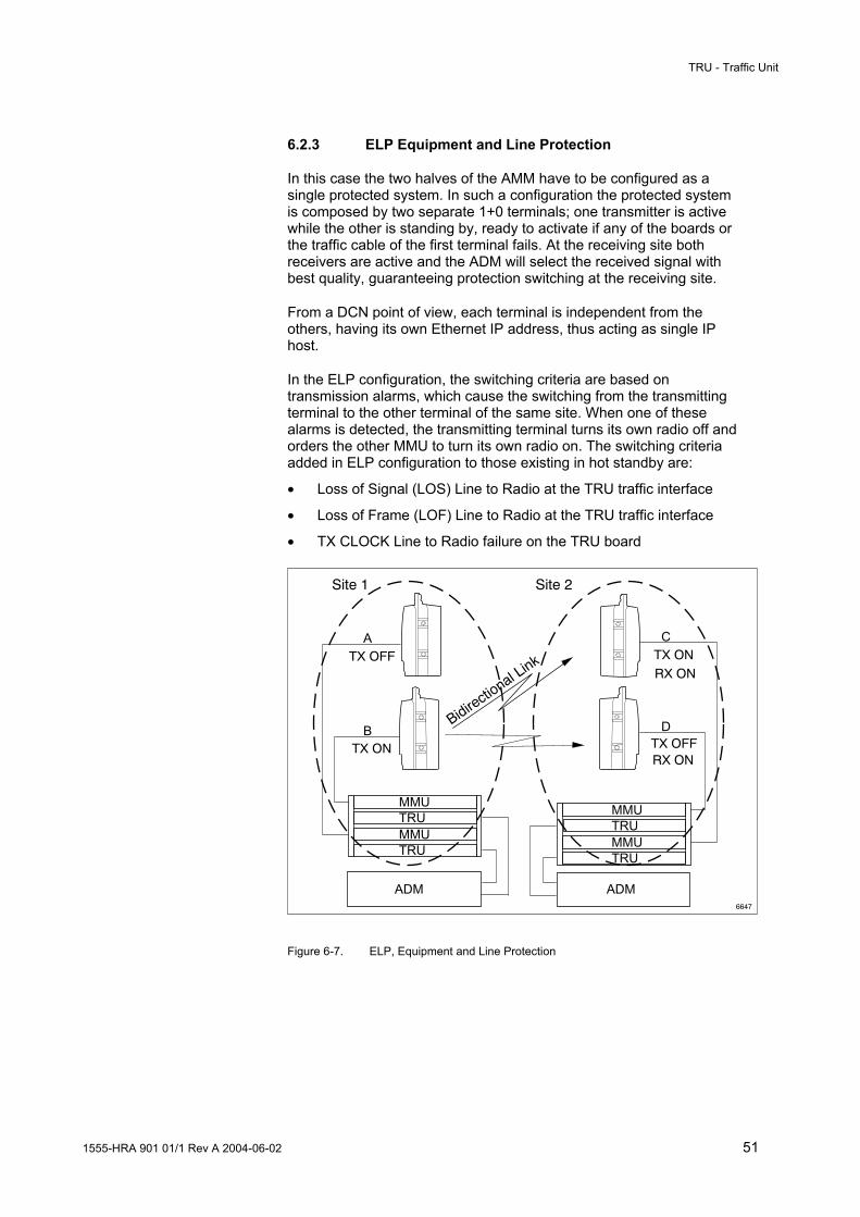
6.2.3 ELP Equipment and Line Protection
In this case the two halves of the AMM have to be configured as a single protected system. In such a configuration the protected system is composed by two separate 1+0 terminals; one transmitter is active while the other is standing by, ready to activate if any of the boards or the traffic cable of the first terminal fails. At the receiving site both receivers are active and the ADM will select the received signal with best quality, guaranteeing protection switching at the receiving site.
From a DCN point of view, each terminal is independent from the others, having its own Ethernet IP address, thus acting as single IP host.
In the ELP configuration, the switching criteria are based on transmission alarms, which cause the switching from the transmitting terminal to the other terminal of the same site. When one of these alarms is detected, the transmitting terminal turns its own radio off and orders the other MMU to turn its own radio on. The switching criteria added in ELP configuration to those existing in hot standby are:
• Loss of Signal (LOS) Line to Radio at the TRU traffic interface
• Loss of Frame (LOF) Line to Radio at the TRU traffic interface
• TX CLOCK Line to Radio failure on the TRU board
6647
Site 1 Site 2
A
B
C
D
TX OFFTX ON
TX OFF TX ONRX ON
RX ON
Bidirectio
nal Link
ADM ADM
MMU
MMU
TRU
TRU
MMU
MMU
TRU
TRU
Figure 6-7. ELP, Equipment and Line Protection

TRU - Traffic Unit
52 1555-HRA 901 01/1 Rev A 2004-06-02
6.3 Functional Blocks
This section describes the main functional blocks of the TRU.
RPS
155 Mbit/s
RST
Opticalinterface
Switch SPI
Electrical interface
155 Mbit/s
User I/O
64 kbit/s V.11
64 kbit/s G.703
Control Processor
Fan alarm
LEDs
RS-232
10/100BaseT
Switch logic
ICC
DC/DCconverter
Primary power from MMU
Waysidetrafficswitch
Secondary voltages
Wayside traffic to/from MMU A
Wayside traffic to/from MMU B
1.5/2 Mbit/s
6619
Bac
kpla
ne
1+1
Alarmsfrom
MMUs
Waysideinterface
64 Kbit/s interfaces
Alarm/Commands
From MMU B
From MMU A
To MMU A
To MMU B
Alarms to/from other boards
Figure 6-8. TRU block diagram
6.3.1 Wayside Interface
Interface for 1.5/2 Mbit/s wayside channel.
6.3.2 Wayside Traffic Switch
The wayside traffic switch provides the protection for the 1.5/2 Mbit/s wayside channel.

TRU - Traffic Unit
1555-HRA 901 01/1 Rev A 2004-06-02 53
6.3.3 Optical/Electrical Interface
Line interfaces for the 155 Mbit/s signal.
6.3.4 Switch
The main function of the block is to select between electrical and optical type of interface for the 155 Mbit/s signal.
6.3.5 Synchronous Physical Interface (SPI)
The transmit and receive traffic signals are pulse shaped. If the STM1/OC-3 signal at input port fails or does not contain enough transmission, a detector inserted in the SPI sends a Loss of Signal (LOS) alarm to the RST block.
6.3.6 Regenerator Section Termination (RST)
This block implements in a bi-directional way the regenerator section termination of the RSOH bytes. See also section 2.3.1 for a description of which bytes that are used.
The following channels are multiplexed into the RSOH to be transmitted over the radio path (see section 9.2.1 for more detailed information):
• Two 64 kbit/s service channels (V.11 and G.703 both codirectional and contradirectional).
• EOC and DCC, 192 kbit/s respectively. Used for exchange of control and supervision information between near-end and far-end terminal
4665
1-9 10-274
1-3
4
5-9 MSOH
AU PointersPayload
RSOH
5220
+RFCOH
Figure 6-9. RSOH in the SDH/SONET frame

TRU - Traffic Unit
54 1555-HRA 901 01/1 Rev A 2004-06-02
6.3.7 Radio Protection Switching (RPS)
The RPS provides 1+1 protection for the STM-1/OC-3 signal against channel associated problems due to hardware failure or temporary signal degradations or losses due to propagation effects (rain, multipath).
For more information on the switching function, see section 6.2.2.
6.3.8 Control and Supervision Processor
The microprocessor in the TRU handles all the internal operation and maintenance functions of the terminal. The TRU processor communicates with the slave processors in the other units in the AMM through the ICC bus.
6.3.9 1+1 Switch Logic
The switch logic in the TRU controls the receiver switching.
6.3.10 User I/O
This block implements the following functions available at the user I/O interface:
• Twelve ports selectable as input or output from the LCT
• Alarms conditions and severity are selectable from the LCT
• The input ports are selectable as active high or active low
• The output ports are selectable as “normally open” or “normally closed” in power off state, if not configured as Severity alarms. In the latter case the outputs are “normally closed” in power off state.
The user I/O interface can be configured to collect alarms for fire, power supply failure, intrusion or a summary alarm from different sources. Furthermore, it can also be used for remote control of external equipment like turning on a mast light.
6.3.11 DC/DC Converter
The TRU is powered from one or two MMUs, through the AMM backplane. The DC/DC converter in the TRU produces secondary voltages for the TRU electronics.

AMM - Access Module Magazine
1555-HRA 901 01/1 Rev A 2004-06-02 55
7 AMM - Access Module Magazine
The AMM provides mechanical housing and backplane connection for the MMU and TRU. One or two terminals can be integrated into one common AMM.
Two AMMs for different applications are available:
• AMM 1U-1 for a single unprotected terminal configuration, housing one MMU and one TRU
• AMM 2U-4 for protected or unprotected terminal configurations, housing up to two MMUs and two TRUs
Figure 7-1. AMM 1U-1
Figure 7-2. AMM 2U-4

AMM - Access Module Magazine
56 1555-HRA 901 01/1 Rev A 2004-06-02
7.1 Functional Description
7.1.1 Mechanical Housing
The AMM is a compact magazine, which fits in 19" racks and cabinets, as well as in ETSI and BYB cabinets.
The AMM is made of aluminum. The sidewalls guide the units and conduct the heat away. The aluminum magazine is chromate coated. A front panel protects the cables at the unit fronts. It is perforated at the center to let cooling air through and for visibility of LEDs at the unit fronts. The front panel is painted dark gray. It is closed with two or four screws respectively and folds down vertically around hinges at its lower edge when opened.
All external connections are easy to access at the unit fronts. Front cables are laid to the left and right of the AMM and along the cabinet on the sidewalls of the rack.
7.1.2 Backplane Connections
The indoor units installed in the AMM are interconnected through a backplane at the back of the AMM. The backplane connects traffic, distributes power and contains processor busses for exchange of internal communication.

AMM - Access Module Magazine
1555-HRA 901 01/1 Rev A 2004-06-02 57
7.1.3 Power Distribution
Primary voltage from the MMU power supply is connected in parallel on the backplane for further distribution to TRU.
If a DC failure occurs in an MMU and there is a second MMU installed in the AMM, the functioning MMU supplies the TRU with DC power through the backplane.
4673
PrimaryDC supply
Power connectionin the backplane
DC MMU
TRU
DC/DC
MMUDC/DCDC
TRU
Figure 7-3. Power distribution in the AMM 2U-4 backplane

AMM - Access Module Magazine
58 1555-HRA 901 01/1 Rev A 2004-06-02

Auxiliary Units
1555-HRA 901 01/1 Rev A 2004-06-02 59
8 Auxiliary Units
Auxiliary units are used to enhance or support the functionality. Some of these units are described below. A complete list of such units along with accessories such as mounting devices and installation tools can be found in the Product Catalog.
8.1 Fan Unit
The fan unit contains four fans for increase of the airflow through the AMM. The unit is mounted on top of the AMM in order to provide the necessary cooling for the units in the AMM.
5071 Figure 8-1. Fan unit
Installation brackets for 19" cabinets/racks are included in the figure above. It is possible to fit installation brackets to the fan unit for installation in cabinets/racks with larger aperture/depth dimensions.
A separate fan alarm is issued if two or more fans have stopped working or DC supply to the fan is lost. The fan alarm signal is connected to the TRU front.

Auxiliary Units
60 1555-HRA 901 01/1 Rev A 2004-06-02
8.2 DC Distribution Unit
5072 Figure 8-2. DC Distribution Unit (DDU)
The DC Distribution Unit (DDU) is used to distribute power supply to up to five MMUs or fan units.
The DDU is connected to the primary power supply with a shielded battery cable. The primary power supply should have a fuse to protect the DDU and the battery cable. Each output is protected by an automatic type fuse (6 A) combined with an ON/OFF switch.
The DDU is available in two versions:
• Negative ground, for +24 V The positive pole is connected to the DDU and the negative pole is connected to ground.
• Positive ground, for -48 V The negative pole is connected to the DDU and the positive pole is connected to ground.

Auxiliary Units
1555-HRA 901 01/1 Rev A 2004-06-02 61
Figure 8-3. System configuration for the DDU
1. Primary power supply
2. External fuse for the primary power supply
3. Fuses for the equipment
4. Terminal equipment

Auxiliary Units
62 1555-HRA 901 01/1 Rev A 2004-06-02
8.3 Terminal Server
The terminal server enables integration of MINI-LINK E in the IP based Data Communication Network provided by MINI-LINK HC. The terminal server is connected to the O&M port on the front-end terminal in the MINI-LINK E sub-network, using a serial cable.
Data Communication Network (TCP/IP)
MINI-LINK Manager
6649
MINI-LINK High Capacity
Terminal Server
V.24
MINI-LINK E Sub-network
10/100BaseT
10/100BaseT
Figure 8-4. Terminal server application
An integrated terminal server is also available on request.

Management System
1555-HRA 901 01/1 Rev A 2004-06-02 63
9 Management System
9.1 Overview
Local management at site is performed from the Local Craft Terminal (LCT), which allows access to all operation and maintenance facilities on the terminal, by communication with a web server in the terminal.
The terminal can also be supervised remotely from MINI-LINK Manager, as well as from a Network Management System (NMS), when connected to a TCP/IP based Data Communication Network (DCN).
TRUMMU
High CapacityTerminal
Local Craft Terminal
Data CommunicationNetwork(TCP/IP)
MINI-LINK Manager/Network Management System
6213
TRUMMU
High CapacityTerminal
Figure 9-1. MINI-LINK terminals, LCT and element manager in a DCN

Management System
64 1555-HRA 901 01/1 Rev A 2004-06-02
9.2 Terminal Management
The terminal can be managed from any of the following types of management system:
• Local Craft Terminal (LCT)
• MINI-LINK Manager
• Other NMS
The LCT has a web based user interface and accesses the terminal using HTTP. MINI-LINK Manager or other NMS can be connected to the terminal using SNMPv3 (or SNMPv1) protocol.
MINI-LINK Manager presents the terminal in the network list. A web based user interface, similar to the one in the LCT, can also be opened for alarm monitoring and further configuration facilities.
The context the management system is shown below.
ManagementSystems
LCT
Web browser
MINI-LINKManager
.html
.gifJava
HTTP
SNMPSNMPManager
HTTP Server
SNMP Agent MIB
6212
Terminal
Managed resources
Figure 9-2. Management of MINI-LINK HC terminals
Each terminal handles its own resources. Configuration and settings are stored in the Management Information Base (MIB). The MIB is physically stored in the TRU Central Processor (CP).
The MIB includes all the objects that are available to the external management system. It gives a view of the equipment, its configuration, alarm information and performance data.

Management System
1555-HRA 901 01/1 Rev A 2004-06-02 65
9.2.1 Communication Channels
There are several types of communication channel in the MINI-LINK HC system. The channels are used for internal and external communication, that is for communication between units in the terminal, over the hop and to peripheral systems. The following channels are used:
• Data Communication Channel (DCC)
• Embedded Operation and Maintenance Channel (EOC)
• Internal Communication Channel (ICC)
• Radio Communication Channel (RCC)
Brief descriptions of the channels and what they are used for can be found below.
External Communication
RSOH bytes are reserved for embedded communication channels, DCC and EOC, for transmission of control and supervision data. Each channel has a capacity of 192 kbit/s. The DCC channel is the standard DCN channel in SDH systems. It can only be used for MINI-LINK HC communication when it is not used for supervision of other SDH equipment. The EOC channel is implemented in bytes reserved for media dependent use. The user can either choose the DCC channel or, when it is not available, the EOC channel.

Management System
66 1555-HRA 901 01/1 Rev A 2004-06-02
Internal Communication
The CP communicates with Slave Processors (SP) in the MMU(s) and RAU(s) through internal channels, ICC and RCC.
The ICC has a transfer rate of 128 kbit/s and connects the CP and the SP on the MMU through the backplane. The RCC is used for communication between the MMU and RAU and has a transfer rate of 31.5 kbit/s.
RAU A
SP
SPMMU A
SPMMU B
CPTRU
RCC
RCC
ICC bus
6648
HCCDCC
Far-endterminal
RAU B
SP
Figure 9-3. Internal and external communication channels

Management System
1555-HRA 901 01/1 Rev A 2004-06-02 67
9.3 Data Communication Network (DCN)
Remote supervision of a MINI-LINK HC network over a DCN is realized with a connection to one of the terminals in the network. The TRU is equipped with a 10/100BaseT port for this purpose. Each TRU also holds a router that terminates and routes IP messages, which means that the DCN can be extended throughout the transmission network. The router uses OSPF protocol and handles and secure traffic to/from the O&M port, 10/100BaseT port, service ports and O&M channels over the hop.
The router ensures that O&M data from the 10/100BaseT port is incorporated in the main traffic over the hop, using either the HCC or DCC channel.
For exchange of O&M data between two terminals on the same site, they can be interconnected by the 10/100BaseT ports (alternative 1 in Figure 9-4). Another possibility is to let O&M data pass unaffected between the terminals in the EOC/DCC channel (alternative 2 in Figure 9-4).
Site A
Site B
MINI-LINK Manager
ADM
2 Mbit/s
HCC/DCC
EOC /DCC
STM-1/OC-3
DCN
alternative 2
6214
alternative 1
Add/drop Multiplexer
O&M data
Ethernet
STM-1/OC-3
Hub
ADM
Figure 9-4. Example of how to route of O&M data in a MINI-LINK HC network

Management System
68 1555-HRA 901 01/1 Rev A 2004-06-02
9.4 Management Tools
Local management, such as configuration and setup, is done from the LCT. Remote management can be performed from MINI-LINK Manager or any appropriate NMS. Remote supervision allows monitoring of alarms and performance as well as some configurations.
9.4.1 LCT
All management functions of the terminal can be performed from the LCT, which is a standard portable PC with the Windows operating system and a web browser with Java plug-in installed. Thus the user interface, which is a Java applet, is started up from the web browser.
The LCT is connected on site to the terminal at the O&M connector (RS 232) on the TRU. It is also possible to use the 10/100BaseT (Ethernet) connector.
9.4.2 MINI-LINK Manager
MINI-LINK Manager is the network element manager of the complete MINI-LINK network, including both point-to-point and point-to-multipoint applications. It can either be integrated with a Network Management System (NMS) or used as a stand-alone system. It can also be upgraded to manage a complete multi-technology transmission network.
From a single screen MINI-LINK Manager handles functions such as fault management, performance monitoring, configuration management and security management.
Several users can access any part of the network through multiple clients and one client can view information of several servers.
For more information, see MINI-LINK Manager Technical Description (1550-AOM 901 02/2).
9.4.3 Other Network Management Systems
MINI-LINK HC provides an SNMPv3 (and SNMPv1) agent that can be interfaced with any appropriate NMS.

Management System
1555-HRA 901 01/1 Rev A 2004-06-02 69
9.5 Management Facilities
The management facilities of the LCT are used both for operation and maintenance of the terminal. The user can work with tasks related to fault management, performance management and configuration management.
The LCT user interface has following main menus:
• Setup
• Configuration
• View
• SW Download
During Setup the initial settings for the AMM, protection mode, DCN connection, transmitting frequency and output power are made.
From the Configuration menu the settings for operation of the terminal and traffic are made.
Setup and configuration settings are non-volatile and stored in the TRU.
From the View menu the user can view and monitor alarms and performance measurements. The use of filters allows the operator to remove unwanted information, thus being able to focus on relevant data.
Software can be downloaded by means of the SW Download facility. The upgrading of the program revision in the terminal is performed as a background process and does not lead to any traffic disturbance.
An online Help is available as a separate feature that can be installed on the PC that will be used as LCT.

Management System
70 1555-HRA 901 01/1 Rev A 2004-06-02
9.6 Configuration Management
After the initial setup of the terminal, additional configurations are made from the LCT, see the Operation Manual for further information. Typical areas of configuration are the optical link, user I/O, alarm log and performance measurements.
9.6.1 Configuration Data
All configuration data for the RAU, MMU and TRU is stored in a non-volatile memory that is located on the TRU. Thus, the configuration for the terminal is automatically recovered when a unit is replaced or after a system restart.
It is possible to upload the current saved configuration to the LCT for backup purposes as well as to download a configuration file from the LCT to the TRU.
9.6.2 Board Status
The CP controls each unit if it is connected to the backplane in the AMM in a proper way.
The following states are possible:
• Connected - the board responds in a correct way
• Disconnected - the inserted board does not respond correctly
• Absent - the board is missing
• Mismatch - wrong board is inserted
9.6.3 Inventory Information
The terminal inventory information below is presented in the LCT.
Unit type Specifies the sort of plug-in unit, such as MMU or TRU.
HW release Specifies the revision of the unit.
Product number Specifies the ordering code for the unit.
Serial number The identification of each unit (factory set.
SW product number Specifies the software loaded in the unit.

Management System
1555-HRA 901 01/1 Rev A 2004-06-02 71
SW release Specifies the revision of the software loaded in the unit.
AMM position Specifies the position in the AMM where the unit is placed.
Inventory data can be saved as a text file on the LCT.
9.6.4 Software Upgrading
The terminal software can be upgraded remotely from an element manager as well as locally from the LCT. The traffic is not affected during this procedure.
A software package, including all images of the units, is downloaded into the terminal from the LCT. The package is compressed to reduce its size. It is then activated either at the end of a successful download or at a later time. When the new software version is downloaded the old version is stored in a memory area, which enables the user to switch back to the old revision if the update fails.

Management System
72 1555-HRA 901 01/1 Rev A 2004-06-02
9.7 Fault Management
Fault Management deals with detection, isolation, and correction of malfunctions. It can be used together with performance management as well, to compensate for environmental changes. Also included are maintenance and examination of error logs and action on alarms.
Each unit is able to report alarm information. Alarms are also indicated by LEDs.
9.7.1 Alarms
There are two types of alarm, active and cleared. Active alarms can be viewed in an alarm list, displayed by the LCT or remotely from the element manager. The alarm list is updated whenever an alarm occurs or clears. The cleared alarms are saved locally in an alarm log in the terminal.
Alarms can be sorted according to the time when the alarm occurred or severity. The alarms are also electrically filtered to prevent occasional failures (like short dips or spikes in the power supply) to cause alarms.
When several alarms occur simultaneously, they are correlated before being reported in order to save network bandwidth.
The alarm information from the terminal includes the name of the alarm, the severity of the alarm, a time record, the board where the alarm is located and its slot number.
For a detailed list of available alarms, see the Operation Manual.
9.7.2 Alarm Severity
Alarms are divided into different severity levels depending on how they affect the traffic, see the table below.
Table 3: Alarm severity
Severity Terminal status Minor An alarm that does not affect the traffic
Major An alarm that may cause a traffic disturbance
Critical An alarm that affects the traffic
Minor alarms are related to malfunctions that do not affect the traffic.
Major alarms are generated when a function is unable to perform a required action. This may cause a disturbance in the traffic.
Critical alarms affect the traffic and should be attended to immediately.

Management System
1555-HRA 901 01/1 Rev A 2004-06-02 73
Depending on the terminal configuration, the alarm severity for an alarm can vary. For example, Loss of Signal (LOS) or Loss of Frame (LOF) conditions from radio side are Critical for a 1+0 configuration and Major for a 1+1 configuration depending on which transmit/receive chain is active.
9.7.3 Loop Tests
Test loops are used during installation, tests and maintenance, which means that it can for example be used for trouble shooting on the terminal. During installation a test signal is connected to the TRU traffic interface and looped back to the corresponding output test for analysis with a BER-meter.
An Alarm Indication Signal (AIS), see section 9.7.4, is generated when a loop is set.
By using test loops the error can be isolated to a specific unit in the near-end or far-end terminal. There are two types of test loops:
• Near-end test loop
• Far-end test loop
Near-end Near-end test loops are used to find out if any of the units in the near-end terminal is faulty (TRU, MMU or RAU).
RAU MMU TRU
Near-end Far-end
N2N1 N3 N4
TRU MMU RAU
4869 Figure 9-5. Near-end loops
The following near-end test loops are available (the numbers in brackets after each loop refer to Figure 9-5):
• TRU Tx Loop (N1) the received traffic signal is looped back, at the SPI block, to the output of the TRU
• TRU Tx Loop (N2) the transmitted traffic signal is looped back, at the RPS block, to the receiving side
• MMU IF Loop (N3) the signal to be transmitted is, after being modulated, mixed with the frequency of a local oscillator and looped back for demodulation (on the receiving side)
• RAU RF loop (N4) a fraction of the RF signal transmitted is shifted in frequency and looped back to the receiving side

Management System
74 1555-HRA 901 01/1 Rev A 2004-06-02
Far-end The far-end test loop is used in order to find out if any of the units in the far-end terminal is faulty (TRU, MMU or RAU).
RAU MMU TRU
Near-end Far-end
F1
TRU MMU RAU
4870 Figure 9-6. Far-end loops
The following far-end loop test is available (the number in brackets after the loop refers to Figure 9-6):
• TRU Rx Loop (F1): the traffic signal being received is looped back to the transmitting side at the SPI block
9.7.4 Alarm Indication Signal
The Alarm Indication Signal (AIS) is used to indicate faults or states, for example that a loop test is set. The AIS is implemented according to the ITU-T recommendation G.783.
AIS is inserted in the radio signal when:
• LOS is detected at the traffic input port or inside the equipment
• LOF is detected at the receiver or inside the equipment
• BER is exceeding a user-defined threshold (this insertion can be enabled by the user)
• The J0 byte, extracted from the received SDH stream, differs from the data written in J0 register (this function is enabled from the LCT)
• Near-end N1 loop and far-end F1 loop

Management System
1555-HRA 901 01/1 Rev A 2004-06-02 75
9.8 Performance Management
Performance Management can be described as a set of functions to evaluate and report the behavior of the equipment and to analyze the effectiveness. It also includes sub-functions to gather statistical information. The performance management is based on the ITU-T G.826 and M.2120 recommendations.
9.8.1 Received Signal Level Monitoring
The received signal is measured for the monitoring of:
• Antenna alignment (measured with external voltmeter connected to the RAU)
• Path acceptance – to check that the actual RF input level equals the one predicted (measured with the LCT)
• Alarm generation
• RF input monitoring (measured with the LCT)
9.8.2 Performance Data
The performance data used for measurement is gathered in 15-minute windows. The 15-minute window starts 00, 15, 30 and 45 minutes past the hour.
Furthermore, performance data is gathered during a 24-hour period. The sampling of data starts at 00.00 hours.
At the end of the window period the gathered data is stored in a circular queue memory. For each new block of data the oldest stored information is removed and the newest is stored, thus constantly keeping the most up-to-date values.
The running performance counters can be reset and the thresholds can be altered manually from the LCT.
ITU G.826 Performance Data
The CP computes the following values using B1 BIP-8 parity:
• Errored Seconds (ES)
• Severely Errored Seconds (SES)
• Unavailable Seconds (UAS)
• Background Block Errors (BBE)

Management System
76 1555-HRA 901 01/1 Rev A 2004-06-02
Two threshold levels (activation and deactivation) are used for the ES and BBE counter in the 15 min windows. When the measured value exceeds the threshold level for activation a notification is generated. The notification is reset at the end of the window period that is active when the counter falls below the deactivation level and no SES occurs.
The SES counter has no deactivation level, the notification is reset at the end of the first 15-min window period where no SES occur.
The notifications for the 24-hour counters (ES, SES and BBE) are reset at the end of the day.
The system can handle data from 16 windows and 24 hours data for the last day along with the active window.
ETSI EN 301 129 Performance Data
The RAU computes the following values:
• Received Level Tide Mark (RLTM)
• Transmitted Level Tide Mark (TLTM)
• Received Level Threshold Seconds (RLTS1 and RLTS2)
• Transmitted Level Threshold Seconds (TLTS)
Programmable thresholds are used for increasing the RLTS1, RLTS2 and TLTS counters.
An additional threshold level is used for the RLTS1 and TLTS counters in the 15 min and 24-hour windows. When the measured value exceeds the threshold level a notification is generated. The notification is reset at the end of the current window.
For RLTM, TLTM, RLTS and TLTS the system can handle 15 minutes data from 16 windows and 24 hours data for 30 days along with the active window.
For protected terminals, the Protection Switch Actual Count (PSAC) is also counted. The system can handle 15 minutes data for 16 windows and 24 hours data for the last day along with the active window.
For protected terminals, the Protection Switch Actual Count (PSAC) is also counted. The system can handle data from 16 windows and 24 hours data for the last day along with the active window.
Management System
1555-HRA 901 01/1 Rev A 2004-06-02 77
9.9 Security
The built-in security functions protect the terminal and its services from disturbances due to illegal activities performed by non-authorized personnel.
9.9.1 Access Control
The access control is carried out when the user accesses the terminal from the LCT or when the Java based user interface is started from MINI-LINK Manager.
The user has to log on to the management system by using a user name and a password to be able to use the management facilities. The following modes are available:
• Local Control
• Local View
• Remote Control
• Remote View
The local modes are performed from the LCT and the remote modes refer to the user interface started from MINI-LINK Manager. The user interfaces are different, depending how the user has logged on. The remote user can do fewer settings than a local user. Traffic disturbing commands are, for example, not possible to execute from remote site.
Depending on the selected mode the user will be able to get read only access or read/write access to the system.
• Control – view settings, make and save changes
• View – view settings only. Not allowed to make changes
9.9.2 Authentication
The authentication mechanism for SNMPv3 access provides data integrity using MD5 as authentication protocol.

Management System
78 1555-HRA 901 01/1 Rev A 2004-06-02

Glossary
1555-HRA 901 01/1 Rev A 2004-06-02 79
Glossary
ADM Add/drop Multiplexer
AFC Automatic Frequency Control
AGC Automatic Gain Control
AIS Alarm Indication Signal
Alignment Port Test port that indicates received signal level used for antenna alignment
AMM Access Module Magazine
ANSI American National Standards Institute
ASK Amplitude Shift Keying
ATPC Automatic Transmit Power Control
BBE Background Block Error
BER Bit Error Rate
BSC Base Station Controller
CP Central Processor
CW Continuous Wave
DCC Data Communication Channel
DCN Data Communication Network
DDU DC Distribution Unit
ELP Equipment and Line Protection
EOC Embedded Operation and Maintenance Channel
ES Errored Seconds
ETSI European Telecommunications Standards Institute
Far-end The terminal with which the near-end terminal communicates
FEC Forward Error Correction
FTP File Transfer Protocol
Hop A radio link connection with a pair of communicating terminals
HRAN High Capacity Radio Access Transmission Network
HTTP Hyper Text Transfer Protocol
HW Hardware
IF Intermediate Frequency
ICC Internal Communication Channel
ITU-R International Telecommunication Union, Radiocommunication Sector
ITU-T International Telecommunication Union, Telecommunication Standardization Sector
L2R Line to radio

Glossary
80 1555-HRA 901 01/1 Rev A 2004-06-02
LAN Local Area Network
LCT Local Craft Terminal
LED Light Emitting Diode
Line side Incoming or outgoing electrical or optical data stream to the terminal
LO Local Oscillator
MIB Management Information Base
MINI-LINK Manager MINI-LINK element management application
MMU Modem Unit
MG Mobility Gateway
MS-AIS Multiplex Section Alarm Indication Signal
MSC Mobile services Switching Center
MTBF Mean Time Between Failure
Near-end The selected terminal
NMS Network Management System
O&M Operation and Maintenance
OC-3 Optical Carrier level 3
OSPF Open Shortest Path First
PLL Phase Locked Loop
PSAC Protection Switching Actual Count
QAM Quadrature Amplitude Modulation
R2L Radio to Line
Radio side Traffic that is transmitted or received over the radio hop
RAU Radio Unit
RCC Radio Communication Channel
RF Radio Frequency
RNC Radio Network Controller
RFCOH Radio Frame Complementary Overhead
RPE Radiation Pattern Envelope
RPS Radio Protection Switching
RSOH Regenerator Section Overhead
RSM Remote Subscriber Multiplexer
RSSI Received Signal Strength Indicator
RST Regenerator Section Termination
SC Service Channels
Site A place with one or several terminals
SDI SDH Physical Interface
SDH Synchronous Digital Hierarchy
SELV Safety Extra Low Voltage
SES Severely Errored Seconds
SNMP Simple Network Management Protocol
SPI Synchronous Parallel Interface
SONET Synchronous Optical Network

Glossary
1555-HRA 901 01/1 Rev A 2004-06-02 81
STM-1 Synchronous Transmission Module 1
SW Software
TCP/IP Transmission Control Protocol/Internet Protocol
Terminal One side of a radio link connection
TRU Traffic Unit
UAS Unavailable Seconds
Unit Exchangeable part of a terminal
VCO Voltage-controlled Oscillator
WAN Wide Area Network
WST Wayside Traffic

Glossary
1555-HRA 901 01/1 Rev A 2004-06-02 82

Index
1555-HRA 901 01/1 Rev A 2004-06-02 83
Index
A
Access Module Magazine (AMM).......................55 AFC.....................................................................31 AIS ......................................................................74 Alarm
list ...................................................................72 log ...................................................................72 severity ...........................................................72
Alarm Indication Signal (AIS)..............................74 Alarms.................................................................72 AMM ...................................................................55 Antenna ..............................................................33
alignment ..................................................23, 75 alignment port .................................................31 installation.......................................................36
ATPC ..................................................................20 Automatic Frequency Control (AFC) ..................31 Automatic Transmit Power Control (ATPC ).......20
B
Block diagram MMU ...............................................................40 RAU1 L ...........................................................26 RAU2 L ...........................................................27 TRU ................................................................52
C
Central Processor...............................................64 Communication channels ...................................65 Configuration management ................................70
D
Data Communication Channel (DCC) ................65 Data Communication Network (DCN) ...21, 46, 63,
67 DC Distribution Unit (DDU).................................60 DCC....................................................................65 DDU....................................................................60 Demodulator .......................................................42
E
ELP Equipment and Line Protection.................. 51 Embedded Operation and Maintenance Channel
(EOC)............................................................. 65 EOC ................................................................... 65 Ethernet and E1 interfaces .................................. 9
F
Fan unit .............................................................. 59 Far-end loop....................................................... 74 Fault management ............................................. 72
H
Hot standby mode.............................................. 15
I
ICC..................................................................... 65 Indoor units .......................................................... 8 Installation manual ............................................... 6 Integrated power splitter .................................... 34 Interfaces
MMU............................................................... 38 RAU1 L .................................................... 24, 28 RAU2 L .................................................... 24, 28 TRU................................................................ 46
Internal Communication Channel (ICC)............. 65 Inventory information ......................................... 70
L
LCT .................................................................... 68 Local Craft Terminal (LCT) ................................ 68 Loop tests .......................................................... 73
M
Main traffic (155 Mbit/s) ..................................... 18 MINI-LINK Manager ........................................... 68 MMU .................................................................. 37 Modem Unit (MMU)............................................ 37 Modulator ........................................................... 41

Index
84 1555-HRA 901 01/1 Rev A 2004-06-02
N
Near-end loop.....................................................73
O
OC-3 ...................................................................18 Operation manual .................................................6 OSPF protocol ....................................................67 Outdoor units ......................................................10
P
Performance data ...............................................75 Performance management .................................75 Phase Locked Loop (PLL) ..................................29 PLL .....................................................................29 Polarization.........................................................33 Power
detector...........................................................29 splitter .............................................................10
Product Catalog....................................................6 Protected terminal 1+1 .......................................14 Protection switching 1+1 ....................................48
R
Radio cable.........................................................10 Radio Communication Channel (RCC) ..............65 Radio Protection Switching (RPS)......................54 Radio Unit (RAU)................................................23 RAU ....................................................................23 RAU1 L
Functional blocks............................................26 RAU1 N...............................................................23 RAU2 L
Fucntional Blocks ...........................................27 RAU2 N...............................................................23 RCC....................................................................65 Received signal level monitoring........................75 Received Signal Strength Indicator (RSSI) ........31 Receiver
Blocks .............................................................30 oscillator..........................................................30
switching ........................................................ 49 Regenerator Section Overhead (RSOH) ..... 19, 47 Regenerator Section Termination (RST) ........... 53 RPS.................................................................... 54 RSOH........................................................... 19, 47 RSSI................................................................... 31 RST.................................................................... 53
S
SDH frame.............................................................. 19 STM-1 ............................................................ 18
Security .............................................................. 77 Slave Processor (SP)................................... 28, 66 Software upgrading............................................ 71 SONET
frame.............................................................. 19 OC-3............................................................... 18
SPI ..................................................................... 53 Synchronous Physical Interface (SPI) ............... 53
T
Terminal configurations................................................. 12 management .................................................. 64 server ............................................................. 62
Traffic Unit (TRU)............................................... 45 Transmitter
blocks............................................................. 29 oscillator......................................................... 29 switching ........................................................ 48
TRU.................................................................... 45
U
Unprotected terminal 1+0 .................................. 12 User I/O.............................................................. 54
W
Working standby mode ...................................... 16


Ericsson ABTransmission & Transport Networks
SE-431 84 Mölndal, SwedenTelephone +46 31 747 00 00Telefax + 46 31 27 72 25
www.ericsson.com
EN/LZT 712 0050 R3A
© Ericsson AB 2004 - All Rights Reserved