Embed Size (px)
Citation preview
Assembly Manual
Mini Funtana
2
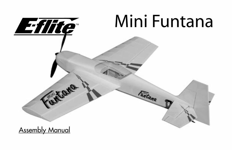
Table of ContentsIntroduction ..................................................... 2Specifications .................................................. 3Additional Required Equipment ......................... 3Additional Tools and Adhesives ......................... 3Optional Parts ................................................. 4Important Information About Motor Selection ...... 4Before Starting Assembly .................................. 4Using the Manual ............................................ 4Warning ......................................................... 4Contents of Kit/Parts Layout .............................. 5Warranty Information ....................................... 6Landing Gear Installation .................................. 7Aileron Hinging ............................................. 11Aileron Servos and Linkages ........................... 14Wing Installation ........................................... 18Stabilizer and Elevator ................................... 20Rudder and Fin .............................................. 24Motor Installation ........................................... 27Rudder and Elevator Servos ............................ 30Receiver, Battery and ESC Install ..................... 32Canopy Install ............................................... 35Cowling Install .............................................. 37Control Throws .............................................. 39Center of Gravity ........................................... 40Range Test Your Radio .................................... 412004 Official AMA National Model Aircraft Safety Code ............................ 42
IntroductionThank you for purchasing the E-flite Mini Funtana 3D ARF Park Flyer. The Mini Funtana is an extreme 3D aerobatic electric park flyer, based on the proven abilities of the popular Hangar 9 FuntanaS airplanes. We developed this aerobatic performer especially for park flyers pilots who are looking for great 3D performance.
The designed characteristics incorporated into the Mini Funtana, in addition to the lightweight balsa and light-ply construction, should provide you with the optimized precision 3D freestyle aerobatics you desire. We also include plenty of extras like the carbon fiber landing gear, fiberglass cowl and wheel pants, and a gearbox that easily accepts one of our popular Park 400 Brushless Motors (EFLM1100 or ELFM1105- purchased separately).
SpecificationsWingspan: 37 in (940 mm)Length: 36 in (915 mm)Wing Area: 329 sq in (21 sq dm)Weight w/o Battery: 18.5 oz (525 g)Weight w/ Battery: 20–24 oz (565–680 g)
3
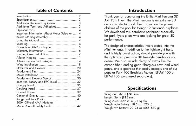
Additional Tools and Adhesives
ToolsSquare T-pinsHobby knife DrillRuler Felt-tipped penHex wrench: 3/32"Phillips screwdriver (small)Drill bit: 3/32" (2.5mm), 1/8" (3mm)
AdhesivesThin CA Medium CA6-minute epoxy Canopy glueThreadlock
OtherHeat gun Paper towelsWax paper 150–180 grit sandpaper
Additional Required Equipment
Recommended JR® SystemsRadio: JR 4-channelServos: JR 241 Sub-micro servo (JRPS241) (4)Receiver: JR R610M 6-channel micro FM Rx (JRPR610 or
JRPR610UL)Or purchase:JR Quattro Lite system (JRP4487) and
(2) JR 241 Sub-micro servo (JRPS241)Other Radio accessories:Large Arms w/Screws (JRPA212) (2)6" (150mm) Servo Extension (JRPA095) (2)9" (230mm) Servo Extension (JRPA097) (2)
Battery and Speed Control RequirementsLi-Po Battery: 11.1V 1800–2100 3-Cell (EFLB1025,
EFLB1035 or THP21003S)Speed Control: E-Flite 20 amp brushless ESC (EFLA311) or
Castle 25 amp brushless ESC (CSEPHX25)
Motor/Gearbox/Propeller6.6:1 gearbox (included) (EFLM221)12x6 Propeller (included) (EFLP1260)Park 400 Brushless Motor, 4200KV (EFLM1100)Park 400 Brushless Motor, 3700KV (EFLM1105)
4
Optional Parts11x4.7 Slow Flyer Propeller (2) EFLP114711x7 Slow Flyer Propeller (2) EFLP117012x3.8 Slow Flyer Propeller (2) EFLP1238Celectra™ 1- to 3-cell LiPo Charger EFLC3005Spur Gear, 66T w/Shaft EFLM222Pinion Gear, 10T (0.4 module) EFLM207
Before Starting AssemblyBefore beginning the assembly of your Mini Funtana 3D, remove each part from its bag for inspection. Closely inspect the fuselage, wing panels, rudder and stabilizer for damage. If you find any damaged or missing parts, contact the place of purchase.
Using the ManualThis manual is divided into sections to help make assembly easier to understand, and to provide breaks between each major section.
Remember to take your time and follow the directions.
WarningAn RC aircraft is not a toy! If misused, it can cause serious bodily harm and damage to property. Fly only in open areas, preferably at AMA (Academy of Model Aeronautics) approved flying sites, following all instructions included with your radio.
Important Information About Motor Selection
We are recommending either the E-flite Park 400 Brushless Motor with 4200Kv (EFLM1100) or the version with 3700Kv (EFLM1105). The 3700Kv motor provides plenty of power for sport and entry level 3D pilots with the ability to hover and climb vertically using the stock 6.6:1 gearbox and 12 x 6 propeller. This motor will draw less current and provide longer flight duration. The 4200Kv motor should only be used by experienced pilots who manage throttle appropriately. This motor will provide even better vertical performance at the expense of flight duration due to the increased current draw. It is extremely important to monitor gearbox wear and motor temperature when using the 4200Kv motor. Lack of proper throttle management using this motor may result in damage to the motor, gearbox, esc, and battery.
5
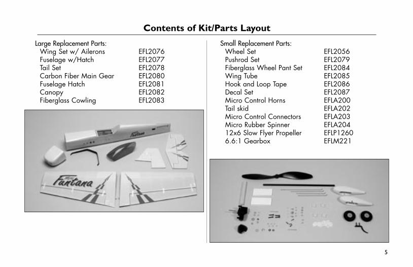
Contents of Kit/Parts Layout
Large Replacement Parts:Wing Set w/ Ailerons EFL2076Fuselage w/Hatch EFL2077Tail Set EFL2078Carbon Fiber Main Gear EFL2080Fuselage Hatch EFL2081Canopy EFL2082Fiberglass Cowling EFL2083
Small Replacement Parts:Wheel Set EFL2056Pushrod Set EFL2079Fiberglass Wheel Pant Set EFL2084Wing Tube EFL2085Hook and Loop Tape EFL2086Decal Set EFL2087Micro Control Horns EFLA200Tail skid EFLA202Micro Control Connectors EFLA203Micro Rubber Spinner EFLA20412x6 Slow Flyer Propeller EFLP12606.6:1 Gearbox EFLM221
6
Please note that once assembly of the model has been started, you must contact Horizon Hobby, Inc. directly regarding any warranty question. Please do not contact your local hobby shop regarding warranty issues, even if that is where you purchased it. This will enable Horizon to better answer your questions and service you in the event that you may need any assistance.
If the buyer is not prepared to accept the liability associated with the use of this product, the buyer is advised to return this kit immediately in new and unused condition to the place of purchase.
Horizon Hobby, Inc. 4105 Fieldstone Road
Champaign, Illinois 61822 (877) 504-0233
www.horizonhobby.com
Warranty InformationHorizon Hobby, Inc. guarantees this kit to be free from defects in both material and workmanship at the date of purchase. This warranty does not cover any component parts damage by use or modification. In no case shall Horizon Hobby’s liability exceed the original cost of the purchased kit. Further, Horizon Hobby reserves the right to change or modify this warranty without notice.
In that Horizon Hobby has no control over the final assembly or material used for the final assembly, no liability shall be assumed nor accepted for any damage resulting from the use of the final assembled product. By the act of using the assembled product, the user accepts all resulting liability.
7
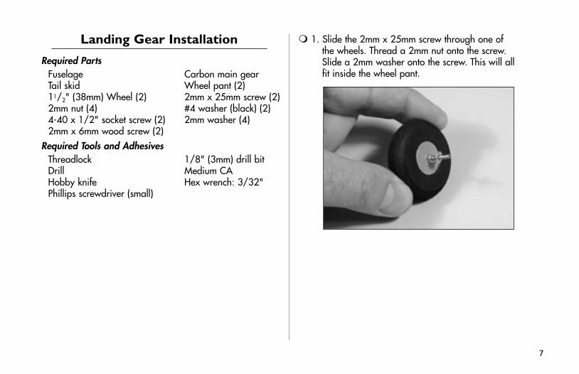
Landing Gear Installation
Required PartsFuselage Carbon main gearTail skid Wheel pant (2)11/2" (38mm) Wheel (2) 2mm x 25mm screw (2)2mm nut (4) #4 washer (black) (2)4-40 x 1/2" socket screw (2) 2mm washer (4)2mm x 6mm wood screw (2)
Required Tools and AdhesivesThreadlock 1/8" (3mm) drill bitDrill Medium CAHobby knife Hex wrench: 3/32"Phillips screwdriver (small)
1. Slide the 2mm x 25mm screw through one of the wheels. Thread a 2mm nut onto the screw. Slide a 2mm washer onto the screw. This will all fit inside the wheel pant.
8
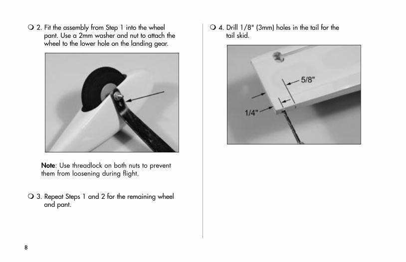
4. Drill 1/8" (3mm) holes in the tail for the tail skid.
2. Fit the assembly from Step 1 into the wheel pant. Use a 2mm washer and nut to attach the wheel to the lower hole on the landing gear.
Note: Use threadlock on both nuts to prevent them from loosening during flight.
3. Repeat Steps 1 and 2 for the remaining wheel and pant.
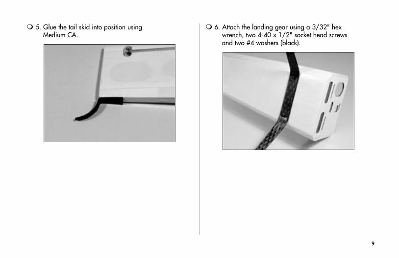
5. Glue the tail skid into position using Medium CA.
6. Attach the landing gear using a 3/32" hex wrench, two 4-40 x 1/2" socket head screws and two #4 washers (black).
9
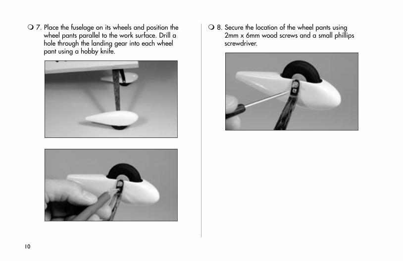
7. Place the fuselage on its wheels and position the wheel pants parallel to the work surface. Drill a hole through the landing gear into each wheel pant using a hobby knife.
8. Secure the location of the wheel pants using 2mm x 6mm wood screws and a small phillips screwdriver.
10
Aileron Hinging
Required PartsWing (left and right) Aileron (left and right)CA hinges (8)
Required Tools and Adhesives3/32" (2.5mm) drill bit DrillT-pins Thin CAPaper towel
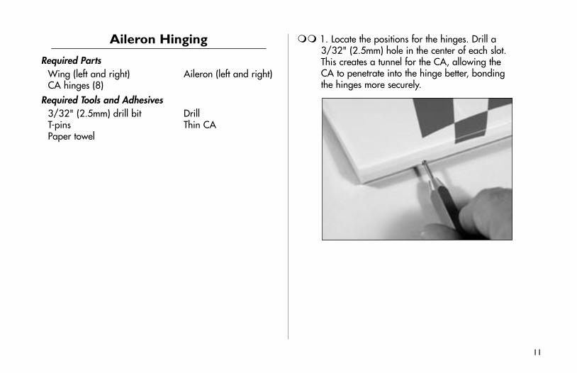
1. Locate the positions for the hinges. Drill a 3/32" (2.5mm) hole in the center of each slot. This creates a tunnel for the CA, allowing the CA to penetrate into the hinge better, bonding the hinges more securely.
11
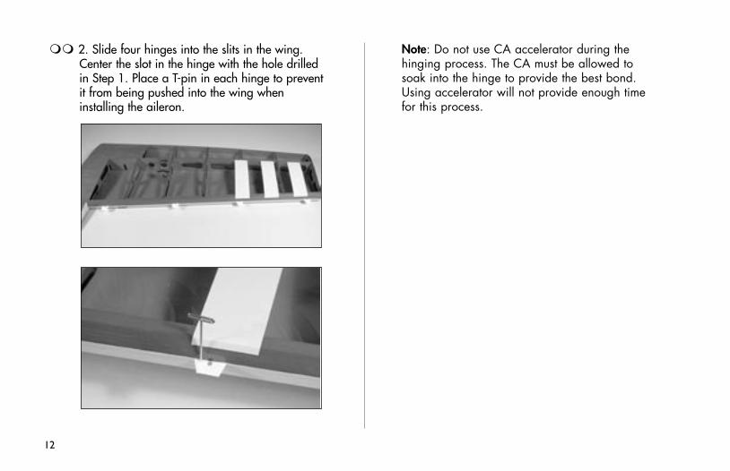
2. Slide four hinges into the slits in the wing. Center the slot in the hinge with the hole drilled in Step 1. Place a T-pin in each hinge to prevent it from being pushed into the wing when installing the aileron.
Note: Do not use CA accelerator during the hinging process. The CA must be allowed to soak into the hinge to provide the best bond. Using accelerator will not provide enough time for this process.
12
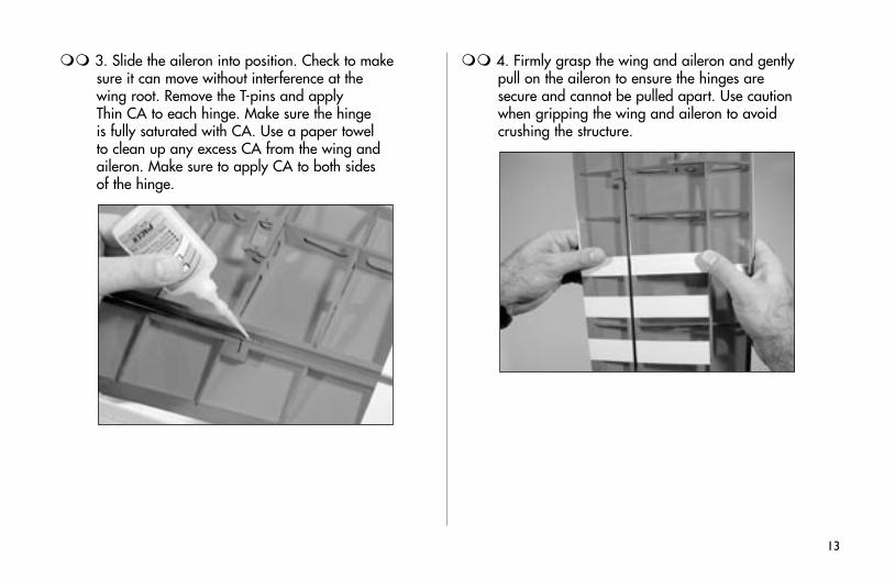
3. Slide the aileron into position. Check to make sure it can move without interference at the wing root. Remove the T-pins and apply Thin CA to each hinge. Make sure the hinge is fully saturated with CA. Use a paper towel to clean up any excess CA from the wing and aileron. Make sure to apply CA to both sides of the hinge.
4. Firmly grasp the wing and aileron and gently pull on the aileron to ensure the hinges are secure and cannot be pulled apart. Use caution when gripping the wing and aileron to avoid crushing the structure.
13
Aileron Servos and Linkages
Required PartsWing panel (right and left)Micro control connector (2)2mm x 4mm screw (2)4" (100mm) pushrod (2)Control horn and backplate (2)Servos: JR 241 Sub-micro servo (JRPS241) (2)Large Arm w/Screws (JRPA212) (2)
Required Tools and AdhesivesHobby knife 6-minute epoxy6" (150mm) servo extension (2) StringPhillips screwdriver (small)
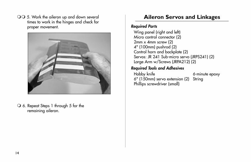
5. Work the aileron up and down several times to work in the hinges and check for proper movement.
6. Repeat Steps 1 through 5 for the remaining aileron.
14
1. Install the grommets and brass eyelets on the servo using instructions provided with the radio system. Attach a 6" (150mm) servo extension. Use string to secure the servo lead and extension to prevent them from unplugging in flight.
Note: We suggest using the Large Arms w/Screws (JRPA212) on all JR® servos for the Mini Funtana. Replace all existing arms before installing the servos.
15
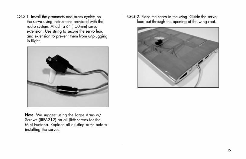
2. Place the servo in the wing. Guide the servo lead out through the opening at the wing root.
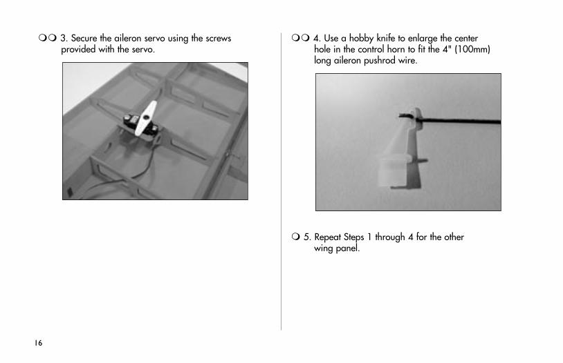
3. Secure the aileron servo using the screws provided with the servo.
4. Use a hobby knife to enlarge the center hole in the control horn to fit the 4" (100mm) long aileron pushrod wire.
5. Repeat Steps 1 through 4 for the other wing panel.
16
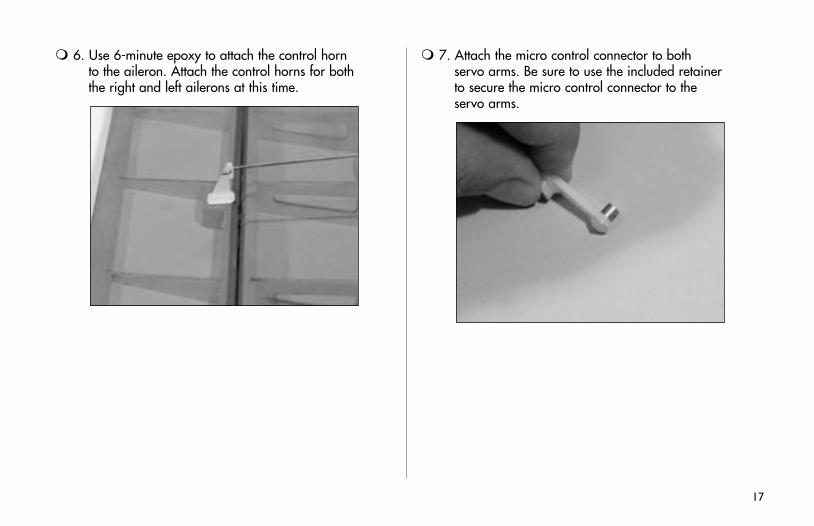
6. Use 6-minute epoxy to attach the control horn to the aileron. Attach the control horns for both the right and left ailerons at this time.
17
7. Attach the micro control connector to both servo arms. Be sure to use the included retainer to secure the micro control connector to the servo arms.
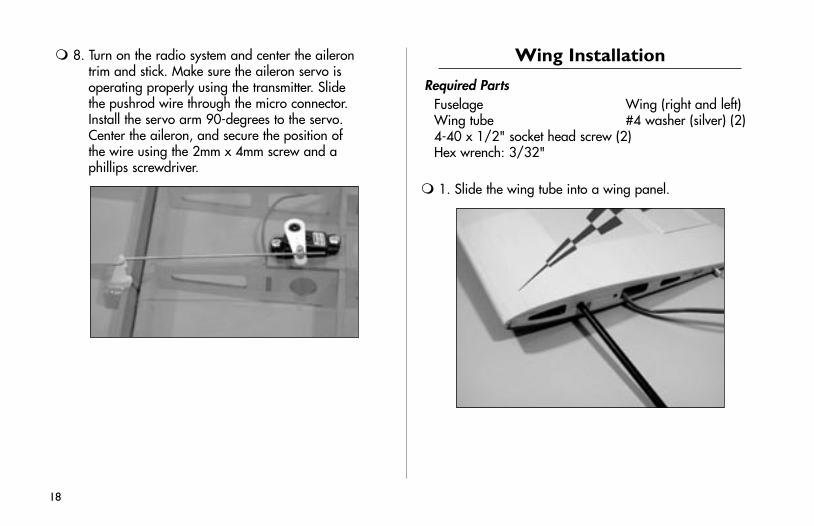
8. Turn on the radio system and center the aileron trim and stick. Make sure the aileron servo is operating properly using the transmitter. Slide the pushrod wire through the micro connector. Install the servo arm 90-degrees to the servo. Center the aileron, and secure the position of the wire using the 2mm x 4mm screw and a phillips screwdriver.
Wing Installation
Required PartsFuselage Wing (right and left)Wing tube #4 washer (silver) (2)4-40 x 1/2" socket head screw (2)Hex wrench: 3/32"
1. Slide the wing tube into a wing panel.
18
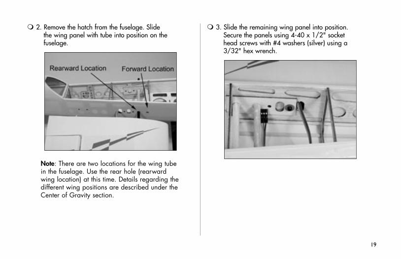
2. Remove the hatch from the fuselage. Slide the wing panel with tube into position on the fuselage.
Note: There are two locations for the wing tube in the fuselage. Use the rear hole (rearward wing location) at this time. Details regarding the different wing positions are described under the Center of Gravity section.
19
3. Slide the remaining wing panel into position. Secure the panels using 4-40 x 1/2" socket head screws with #4 washers (silver) using a 3/32" hex wrench.
Stabilizer and Elevator
Required PartsFuselage w/wing installed StabilizerElevator CA hinge (4)
Required Tools and AdhesivesHobby knife Felt-tipped penRuler T-pinsThin CA
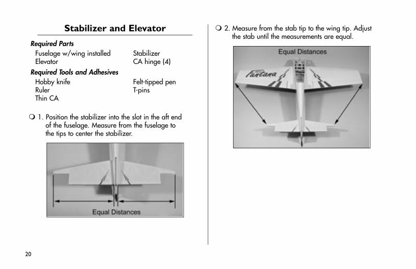
1. Position the stabilizer into the slot in the aft end of the fuselage. Measure from the fuselage to the tips to center the stabilizer.
2. Measure from the stab tip to the wing tip. Adjust the stab until the measurements are equal.
20
21
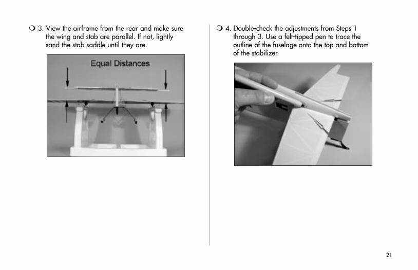
3. View the airframe from the rear and make sure the wing and stab are parallel. If not, lightly sand the stab saddle until they are.
4. Double-check the adjustments from Steps 1 through 3. Use a felt-tipped pen to trace the outline of the fuselage onto the top and bottom of the stabilizer.
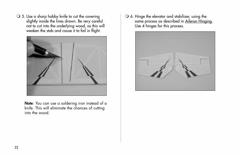
5. Use a sharp hobby knife to cut the covering slightly inside the lines drawn. Be very careful not to cut into the underlying wood, as this will weaken the stab and cause it to fail in flight.
Note: You can use a soldering iron instead of a knife. This will eliminate the chances of cutting into the wood.
6. Hinge the elevator and stabilizer, using the same process as described in Aileron Hinging. Use 4 hinges for this process.
22
23
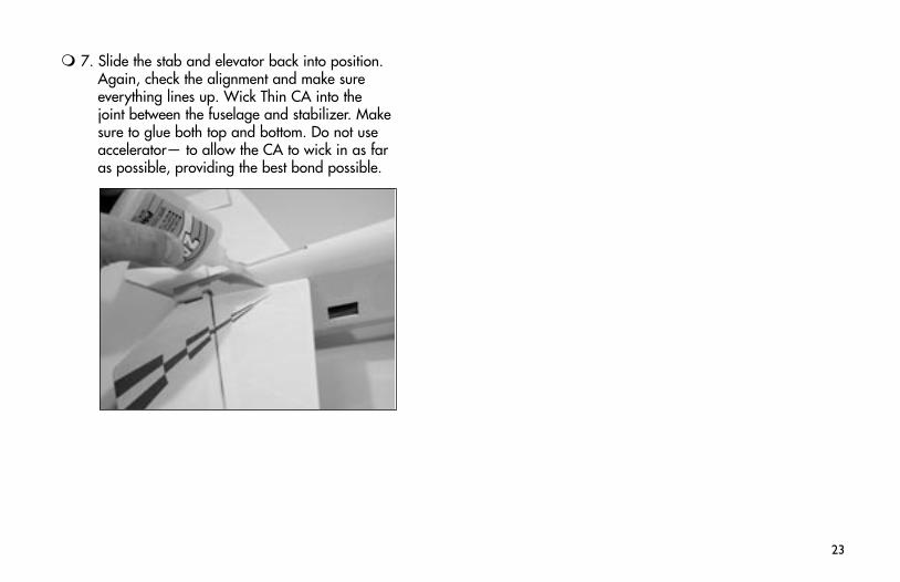
7. Slide the stab and elevator back into position. Again, check the alignment and make sure everything lines up. Wick Thin CA into the joint between the fuselage and stabilizer. Make sure to glue both top and bottom. Do not use accelerator— to allow the CA to wick in as far as possible, providing the best bond possible.
Rudder and Fin
Required PartsFuselage RudderFin CA hinge (3)
Required Tools and AdhesivesHobby knife Thin CAFelt-tipped pen Square
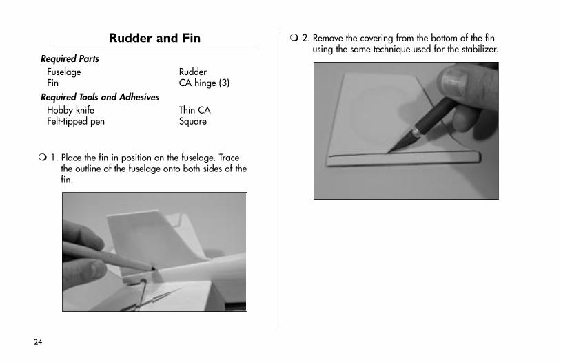
1. Place the fin in position on the fuselage. Trace the outline of the fuselage onto both sides of the fin.
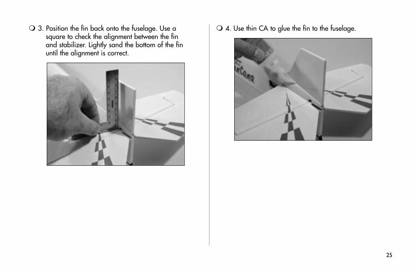
2. Remove the covering from the bottom of the fin using the same technique used for the stabilizer.
24
25
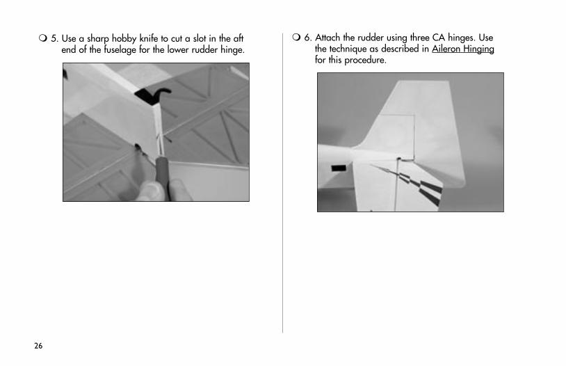
3. Position the fin back onto the fuselage. Use a square to check the alignment between the fin and stabilizer. Lightly sand the bottom of the fin until the alignment is correct.
4. Use thin CA to glue the fin to the fuselage.
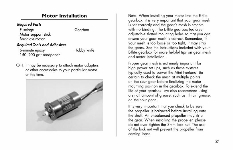
5. Use a sharp hobby knife to cut a slot in the aft end of the fuselage for the lower rudder hinge.
26
6. Attach the rudder using three CA hinges. Use the technique as described in Aileron Hinging for this procedure.
27
Motor Installation
Required PartsFuselage GearboxMotor support stickBrushless motor
Required Tools and Adhesives6-minute epoxy Hobby knife150–200 grit sandpaper
1. It may be necessary to attach motor adapters or other accessories to your particular motor at this time.
Note: When installing your motor into the E-flite gearbox, it is very important that your gear mesh is set correctly and the gear’s mesh is smooth with no binding. The E-flite gearbox features adjustable slotted mounting holes so that you can ensure your gear mesh is correct. Remember, if your mesh is too loose or too tight, it may strip the gears. See the instructions included with your E-flite gearbox for more helpful tips on gear mesh and motor installation.
Proper gear mesh is extremely important for high power set ups, such as those systems typically used to power the Mini Funtana. Be certain to check the mesh at multiple points on the spur gear before finalizing the motor mounting position in the gearbox. To extend the life of your gearbox, we also recommend using a small amount of grease, such as lithium grease, on the spur gear.
It is very important that you check to be sure the propeller is balanced before installing onto the shaft. An unbalanced propeller may strip the gear. When installing the propeller, please do not over tighten the 3mm lock nut. The use of the lock nut will prevent the propeller from coming loose.
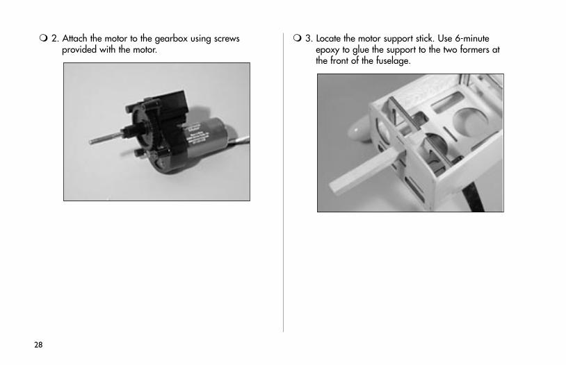
2. Attach the motor to the gearbox using screws provided with the motor.
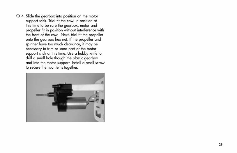
3. Locate the motor support stick. Use 6-minute epoxy to glue the support to the two formers at the front of the fuselage.
28
29
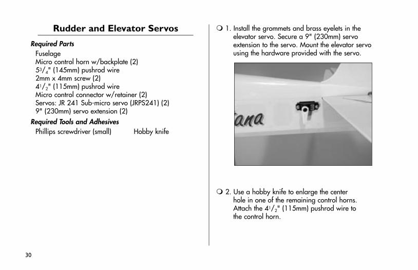
4. Slide the gearbox into position on the motor support stick. Trial fit the cowl in position at this time to be sure the gearbox, motor and propeller fit in position without interference with the front of the cowl. Next, trial fit the propeller onto the gearbox hex nut. If the propeller and spinner have too much clearance, it may be necessary to trim or sand part of the motor support stick at this time. Use a hobby knife to drill a small hole though the plastic gearbox and into the motor support. Install a small screw to secure the two items together.
Rudder and Elevator Servos
Required PartsFuselageMicro control horn w/backplate (2)53/4" (145mm) pushrod wire2mm x 4mm screw (2)41/2" (115mm) pushrod wireMicro control connector w/retainer (2)Servos: JR 241 Sub-micro servo (JRPS241) (2)9" (230mm) servo extension (2)
Required Tools and AdhesivesPhillips screwdriver (small) Hobby knife
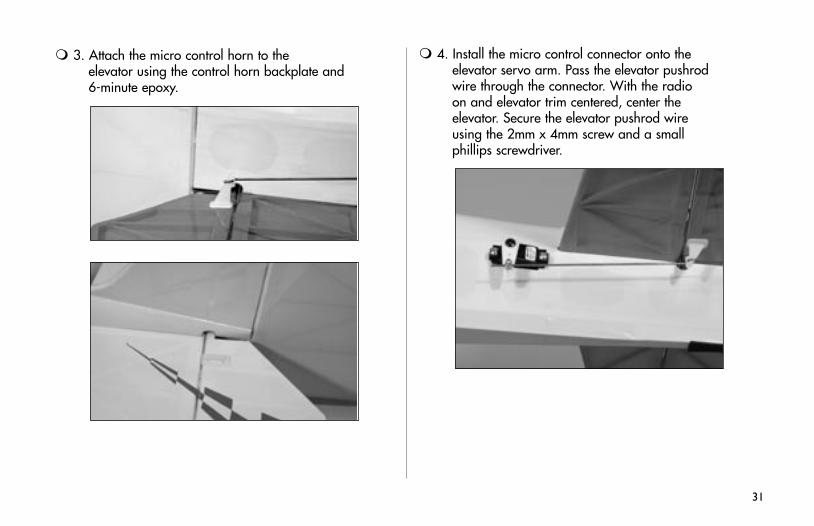
1. Install the grommets and brass eyelets in the elevator servo. Secure a 9" (230mm) servo extension to the servo. Mount the elevator servo using the hardware provided with the servo.
2. Use a hobby knife to enlarge the center hole in one of the remaining control horns. Attach the 41/2" (115mm) pushrod wire to the control horn.
30
31
3. Attach the micro control horn to the elevator using the control horn backplate and 6-minute epoxy.
4. Install the micro control connector onto the elevator servo arm. Pass the elevator pushrod wire through the connector. With the radio on and elevator trim centered, center the elevator. Secure the elevator pushrod wire using the 2mm x 4mm screw and a small phillips screwdriver.
32
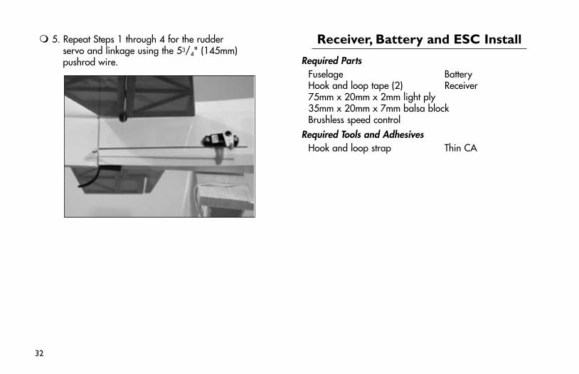
5. Repeat Steps 1 through 4 for the rudder servo and linkage using the 53/4" (145mm) pushrod wire.
Receiver, Battery and ESC Install
Required PartsFuselage BatteryHook and loop tape (2) Receiver75mm x 20mm x 2mm light ply35mm x 20mm x 7mm balsa blockBrushless speed control
Required Tools and AdhesivesHook and loop strap Thin CA
33
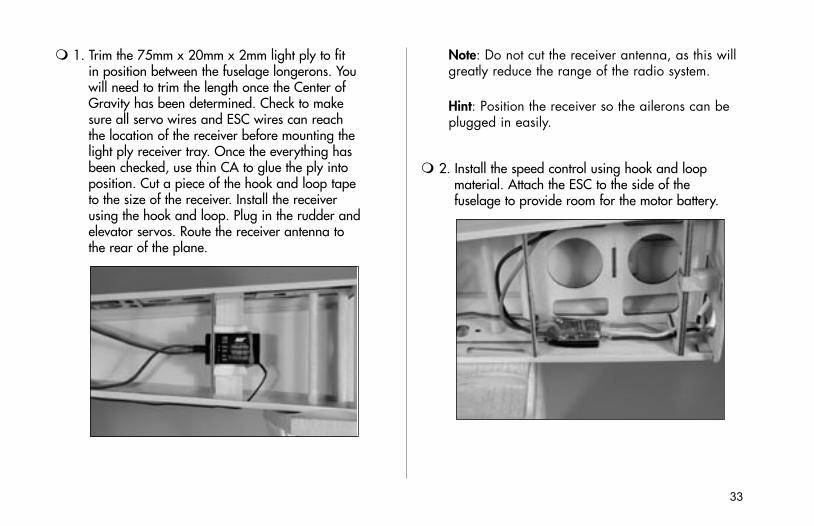
1. Trim the 75mm x 20mm x 2mm light ply to fit in position between the fuselage longerons. You will need to trim the length once the Center of Gravity has been determined. Check to make sure all servo wires and ESC wires can reach the location of the receiver before mounting the light ply receiver tray. Once the everything has been checked, use thin CA to glue the ply into position. Cut a piece of the hook and loop tape to the size of the receiver. Install the receiver using the hook and loop. Plug in the rudder and elevator servos. Route the receiver antenna to the rear of the plane.
Note: Do not cut the receiver antenna, as this will greatly reduce the range of the radio system.
Hint: Position the receiver so the ailerons can be plugged in easily.
2. Install the speed control using hook and loop material. Attach the ESC to the side of the fuselage to provide room for the motor battery.
34
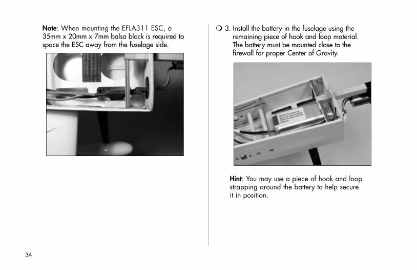
Note: When mounting the EFLA311 ESC, a 35mm x 20mm x 7mm balsa block is required to space the ESC away from the fuselage side.
3. Install the battery in the fuselage using the remaining piece of hook and loop material. The battery must be mounted close to the firewall for proper Center of Gravity.
Hint: You may use a piece of hook and loop strapping around the battery to help secure it in position.
35
Canopy Install
Required PartsFuselage Canopy
Required Tools and AdhesivesCanopy glue Wax paperFelt-tipped pen150–220 grit sandpaper
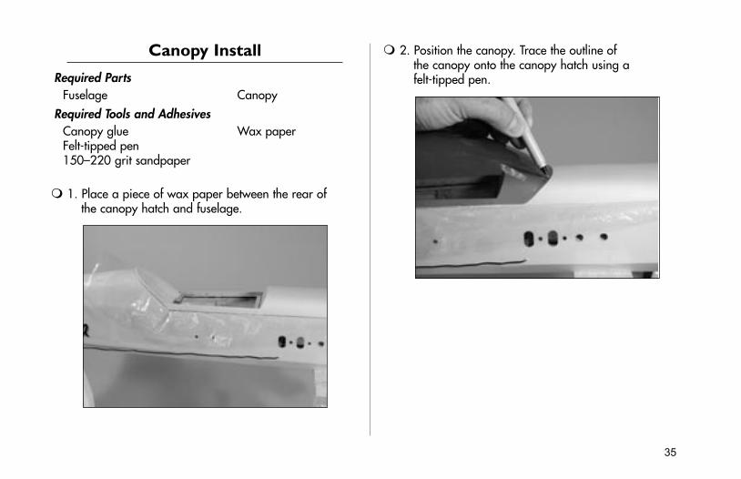
1. Place a piece of wax paper between the rear of the canopy hatch and fuselage.
2. Position the canopy. Trace the outline of the canopy onto the canopy hatch using a felt-tipped pen.
36
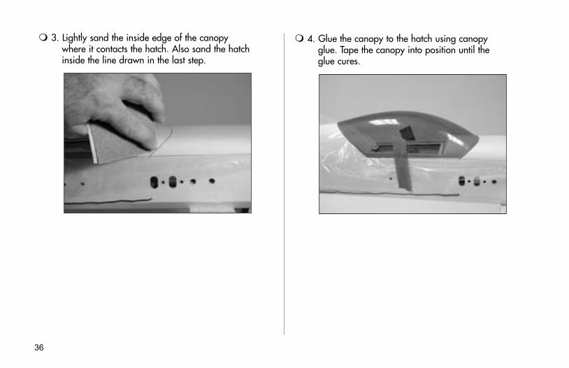
3. Lightly sand the inside edge of the canopy where it contacts the hatch. Also sand the hatch inside the line drawn in the last step.
4. Glue the canopy to the hatch using canopy glue. Tape the canopy into position until the glue cures.
37
Cowling Install
Required PartsFuselage Cowling12x6 propeller Spinner3mm lock nut 3mm washer2mm x 8mm wood screw (4)
Required Tools and AdhesivesHobby knifePhillips screwdriver (small)
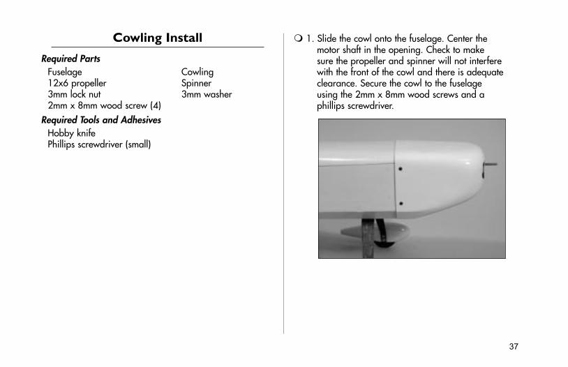
1. Slide the cowl onto the fuselage. Center the motor shaft in the opening. Check to make sure the propeller and spinner will not interfere with the front of the cowl and there is adequate clearance. Secure the cowl to the fuselage using the 2mm x 8mm wood screws and a phillips screwdriver.
38
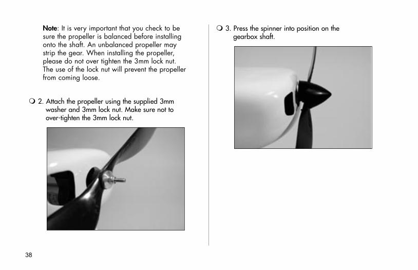
Note: It is very important that you check to be sure the propeller is balanced before installing onto the shaft. An unbalanced propeller may strip the gear. When installing the propeller, please do not over tighten the 3mm lock nut. The use of the lock nut will prevent the propeller from coming loose.
2. Attach the propeller using the supplied 3mm washer and 3mm lock nut. Make sure not to over-tighten the 3mm lock nut.
3. Press the spinner into position on the gearbox shaft.
39
Control Throws
1. Turn on the transmitter and receiver of your Mini Funtana. Check the movement of the rudder using the transmitter. When the stick is moved right, the rudder should also move right. Reverse the direction of the servo at the transmitter if necessary.
2. Check the movement of the elevator with the radio system. Moving the elevator stick down will make the airplane elevator move up.
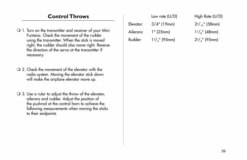
3. Use a ruler to adjust the throw of the elevator, ailerons and rudder. Adjust the position of the pushrod at the control horn to achieve the following measurements when moving the sticks to their endpoints
Low rate (U/D) High Rate (U/D)
Elevator: 3/4" (19mm) 25/16" (58mm)
Ailerons: 1" (25mm) 17/8" (48mm)
Rudder: 13/4" (95mm) 23/4" (95mm)
40
Center of Gravity
An important part of preparing the aircraft for flight is properly balancing the model.
Caution: Do not inadvertently skip this step!
The recommended Center of Gravity (CG) location for the Mini Funtana is 31/8" (80mm) behind the leading edge of the wing against the fuselage. Use this CG and the rearward wing position to the first flights until you have become more experienced.
For experienced pilots and extreme 3D performance, move the wing to the forward location. This will provide a neutral feel when inverted and will allow the Mini Funtana to really cut loose. It is best to increase the exponential values used to maintain a smooth feel. The CG may be placed as far back as 37/16" (88mm).
Note: The wing has two different mounting positions, which provides more flexibility with adjusting the CG. Using the rearward wing position will allow the aircraft to balance at the forward CG for precision aerobatics. The forward wing position is used to achieve the rearward CG for extreme 3D aerobatics.
41
Range Test Your Radio
1. Before each flying session, be sure to range check your radio. This is accomplished by turning on your transmitter with the antenna collapsed. Turn on the receiver in your airplane. With your airplane on the ground and the engine running, you should be able to walk 30 paces (approximately 100 feet) away from your airplane and still have complete control of all functions.
If not, don’t attempt to fly! Have your radio equipment checked out by the manufacturer.
2. Double-check that all controls (aileron, elevator, rudder and throttle) move in the correct direction.
3. Be sure that your transmitter batteries are fully charged, per the instructions included with your radio.
42
2004 Official AMA National Model Aircraft Safety CodeGENERAL
1) I will not fly my model aircraft in sanctioned events, air shows or model flying demonstrations until it has been proven to be airworthy by having been previously, successfully flight tested.
2) I will not fly my model higher than approximately 400 feet within 3 miles of an airport without notifying the airport operator. I will give right-of-way and avoid flying in the proximity of full-scale aircraft. Where necessary, an observer shall be utilized to supervise flying to avoid having models fly in the proximity of full-scale aircraft.
3) Where established, I will abide by the safety rules for the flying site I use, and I will not willfully or deliberately fly my models in a careless, reckless and/or dangerous manner.
4) The maximum takeoff weight of a model is 55 pounds, except models flown under Experimental Aircraft rules.
5) I will not fly my model unless it is identified with my name and address or AMA number, on or in the model. (This does not apply to models while being flown indoors.)
6) I will not operate models with metal-bladed propellers or with gaseous boosts, in which gases other than air enter their internal combustion engine(s); nor will I operate models with extremely hazardous fuels such as those containing tetranitromethane or hydrazine.
RADIO CONTROL
1) I will have completed a successful radio equipment ground range check before the first flight of a new or repaired model.
2) I will not fly my model aircraft in the presence of spectators until I become a qualified flier, unless assisted by an experienced helper.
43
3) At all flying sites a straight or curved line(s) must be established in front of which all flying takes place with the other side for spectators. Only personnel involved with flying the aircraft are allowed at or in the front of the flight line. Intentional flying behind the flight line is prohibited.
4) I will operate my model using only radio control frequencies currently allowed by the Federal Communications Commission. (Only properly licensed Amateurs are authorized to operate equipment on Amateur Band frequencies.)
5) Flying sites separated by three miles or more are considered safe from site-to site interference, even when both sites use the same frequencies. Any circumstances under three miles separation require a frequency management arrangement, which may be either an allocation of specific frequencies for each site or testing to determine that freedom from interference exists. Allocation plans or interference test reports shall be signed by the parties involved and provided to AMA Headquarters. Documents of agreement and reports may exist between (1) two or more AMA Chartered Clubs, (2) AMA clubs and individual AMA members not associated with AMA Clubs, or (3) two or more individual AMA members.
6) For Combat, distance between combat engagement line and spectator line will be 500 feet per cubic inch of engine displacement. (Example: .40 engine = 200 feet.); electric motors will be based on equivalent combustion engine size. Additional safety requirements will be per the RC Combat section of the current Competition Regulations.
7) At air shows or model flying demonstrations, a single straight line must be established, one side of which is for flying, with the other side for spectators.
8) With the exception of events flown under AMA Competition rules, after launch, except for pilots or helpers being used, no powered model may be flown closer than 25 feet to any person.
9) Under no circumstances may a pilot or other person touch a powered model in flight.

7011
© 2004 Horizon Hobby, Inc. 4105 Fieldstone Road
Champaign, Illinois 61822 (877) 504-0233
www.horizonhobby.com