Embed Size (px)
DESCRIPTION
HPDC
Citation preview
4B-1NADCA Product Specification Standards for Die Castings / 2012
Engineering & Design: Miniature Die Casting
4B
S E C T I O N
4BSection Contents NADCA No. Format Page
Frequently Asked Questions (FAQ) 4B-2
1 Introduction 4B-2
2 Typical Design and Tolerance Data S-4B-1-12 Standard 4B-3
3 Miniature Die Casting Machines 4B-4
4 Miniature Die Casting Dies 4B-4
5 Design Considerations for Miniature Die Castings 4B-7
5.1 Weight Reduction 4B-7
5.2 Ribs 4B-7
5.3 Shrinkage 4B-7
5.4 Draft 4B-7
5.5 Uniform Cross Section 4B-8
5.6 Fillets & Radii 4B-8
5.7 Surface Finish 4B-8
5.8 Parting Line & Ejector Pins 4B-8
5.9 Part Identification 4B-9
5.10 Side Cores 4B-9
5.11 Combining Functions 4B-9
5.12 Variations 4B-9
5.13 Skin 4B-10
5.14 Gears 4B-10
5.15 Threads 4B-10
5.16 Insert Die Casting 4B-10
5.17 Crimping, Staking, Bending and Forming 4B-10
6 Available Finishes 4B-11
7 Castable Zinc Alloys 4B-11
8 Glossary of Miniature Die Casting Technology 4B-12
4B-2 NADCA Product Specification Standards for Die Castings / 2012
Engineering & Design: Miniature Die Casting
Frequently Asked Questions (FAQ)
1) What is the difference between Section 4A and Section 4B, Miniature Die Casting? See page 4B-2, Introduction.
2) What is a Miniature Die Cast Machine? See page 4B-4, Miniature Die Cast Machines.
3) How tight can dimensional tolerances be held for mini-zinc castings? See page 4B-3, Typical Design and Tolerance Data.
1 Introduction
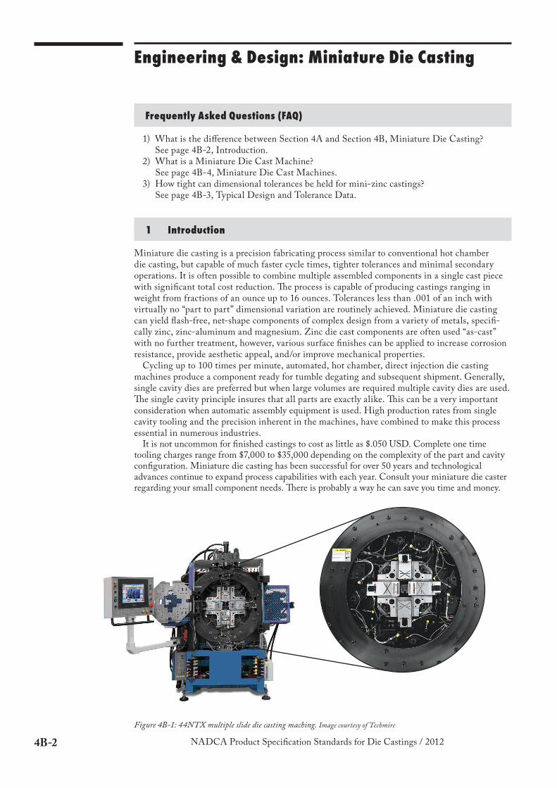
Miniature die casting is a precision fabricating process similar to conventional hot chamber die casting, but capable of much faster cycle times, tighter tolerances and minimal secondary operations. It is often possible to combine multiple assembled components in a single cast piece with significant total cost reduction. "e process is capable of producing castings ranging in weight from fractions of an ounce up to 16 ounces. Tolerances less than .001 of an inch with virtually no “part to part” dimensional variation are routinely achieved. Miniature die casting can yield flash-free, net-shape components of complex design from a variety of metals, specifi-cally zinc, zinc-aluminum and magnesium. Zinc die cast components are often used “as-cast” with no further treatment, however, various surface finishes can be applied to increase corrosion resistance, provide aesthetic appeal, and/or improve mechanical properties.
Cycling up to 100 times per minute, automated, hot chamber, direct injection die casting machines produce a component ready for tumble degating and subsequent shipment. Generally, single cavity dies are preferred but when large volumes are required multiple cavity dies are used. "e single cavity principle insures that all parts are exactly alike. "is can be a very important consideration when automatic assembly equipment is used. High production rates from single cavity tooling and the precision inherent in the machines, have combined to make this process essential in numerous industries.
It is not uncommon for finished castings to cost as little as $.050 USD. Complete one time tooling charges range from $7,000 to $35,000 depending on the complexity of the part and cavity configuration. Miniature die casting has been successful for over 50 years and technological advances continue to expand process capabilities with each year. Consult your miniature die caster regarding your small component needs. "ere is probably a way he can save you time and money.
Figure 4B-1: 44NTX multiple slide die casting maching. Image courtesy of Techmire
4B-3NADCA Product Specification Standards for Die Castings / 2012
Engineering & Design: Miniature Die Casting
4B
2 Typical Design and Tolerance Data
Because of their size and the specialized machines used, miniature die castings can be produced to closer dimensional tolerances than larger castings. One of the advantages of miniature die casting is that ‘part to part’ variations are virtually nonexistent.
Tolerances on hole locations and other details that are influenced by shrinkage are obviously easier to hold on small parts. Tooling is crucial to successful miniature die casting (see page 4B-4 Miniature Die Casting Dies) and when designed and built properly can produce castings that are clean, flash-free and ready-to-use without secondary operations. !is leaves the hard dense surface of the casting undisturbed and thus increases wear resistance and strength.
Note: Tolerances given below have been achieved and are strictly applied to multiple slide, miniature die casting. �e values may vary with size, design, and configuration of the component. Please consult your die caster for establishing tolerances for specific part features.
Linear Dimension +/-0.0008” up to 1” and +/-0.001 for each additional inch
+/-0.020mm up to 25.4mm” and +/-0.025 for each additional 25.4mm
!e following values are typical for a 1.18” (30mm) component.
Flatness 0.002” 0.05 mm
Straightness 0.001” 0.03 mm
Circularity 0.001” (// to parting line) 0.03 mm (// to parting line)
Angularity 0.001 in/in 0.001 mm/mm
Concentricity 0.002” (// to parting line) 0.05 mm (// to parting line)
Minimum Wall !ickness 0.020” 0.50 mm
Surface Finish (See paragraph 5.7) to 32 to 64 microinches 0.8-1.6 microns
Gears (See paragraph 5.14) AGMA 6 - AGMA 8
!reads-External As-Cast (See paragraph 5.15) 2A 6g
NADCA
S-4B-1-12
STANDARD
Note:It is important to note that this section covers tolerances that are achievable for both Standard and Precision Die Castings. However, in today’s Six Sigma World, Capability may still be a question. Die Cast Tools are often built to allow for maximum tool life and process variations that can detract from the process and actual tool capability. Six Sigma variation and CPK should be discussed with the Die Caster in advance of tool construction. Frequently repeatability (CP rather than CPK) is the goal in the as-cast state. To build a tool at nomi-nal dimensions to get a good CPK will lead to shorter tool life and added rejects to the die caster for process variations.
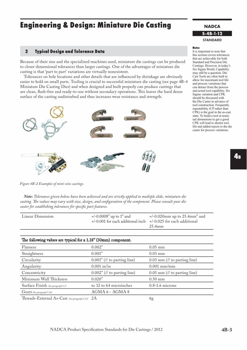
Figure 4B-2 Examples of mini-zinc castings.
4B-4 NADCA Product Specification Standards for Die Castings / 2012
Engineering & Design: Miniature Die Casting
3 Miniature Die Casting Machines
Miniature die casting machines may be small versions of traditional die casting machines or can be what is referred to as multiple-slide machines (see Figure 4B-1). !ese machines are made by several different manufacturers around the world. State of the art technology is available in these completely automated, computer controlled machines. Some die casters custom build their own machines or modify commer-cial machines to better meet the needs of their customers. Miniature die casting machines commonly use two to four slides. Five and even six slides have been used in very complex applications. !e most common “multiple-slide” machine is built to accommodate a two inch square die, but machines made for four, six and eight inch square dies are also utilized.
With four sliding dies forming the details of a component, very intricate features are relatively easy to cast to extremely tight tolerances that are nearly flash-free. Operating at approximately 2000 psi injection pressure, a two inch square, four slide machine, can cycle 100 times per minute. Although average running speeds generally are in the 15-25 cycles per minute range. Pneumatic and/or hydraulic cylinders are used to inject the molten metal into the cavity, as well as, move the slides in and out. Some larger shots may require the use of hydraulic cylinders in order to accom-modate necessary metal pressure and die lock up pressures. Smaller castings require less metal pressure to fill properly and less time to solidify. Usually a blue print of the component is enough to indicate what type of machine is needed to meet specified requirements.
4 Miniature Die Casting Dies
As with any form of die casting, miniature die cast tooling requires several basic consider-ations when designing a die to best meet your needs. Remember your die caster can make this very easy for you since they have specific machine and process requirements that must be addressed. !e most obvious factors are: the shape or geometry of the part, the physical size of the part, the part weight and the production requirements.
!e shape or geometry of a part is probably the most important issue to be considered because the part must be castable and still maintain its intended function. Usually a component(s) in an assembly can be engineered to develop a practical part both castable and functional. If the parts intended function can not be maintained, modifications mentioned after this section are extremely important when developing a part. Your die caster will be able to advise on the most cost effective way to meet your needs.
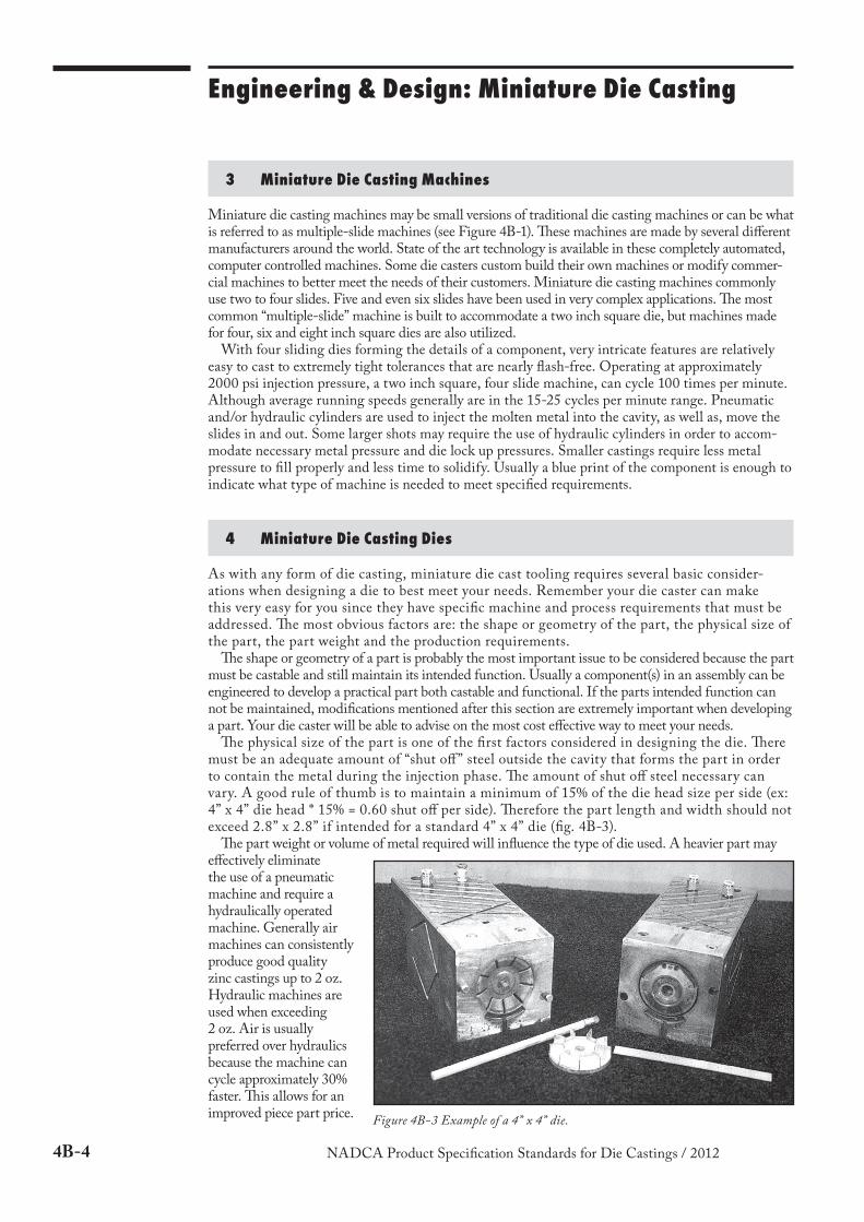
!e physical size of the part is one of the first factors considered in designing the die. !ere must be an adequate amount of “shut off” steel outside the cavity that forms the part in order to contain the metal during the injection phase. !e amount of shut off steel necessary can vary. A good rule of thumb is to maintain a minimum of 15% of the die head size per side (ex: 4” x 4” die head * 15% = 0.60 shut off per side). !erefore the part length and width should not exceed 2.8” x 2.8” if intended for a standard 4” x 4” die (fig. 4B-3).
!e part weight or volume of metal required will influence the type of die used. A heavier part may effectively eliminate the use of a pneumatic machine and require a hydraulically operated machine. Generally air machines can consistently produce good quality zinc castings up to 2 oz. Hydraulic machines are used when exceeding 2 oz. Air is usually preferred over hydraulics because the machine can cycle approximately 30% faster. !is allows for an improved piece part price.
Figure 4B-3 Example of a 4” x 4” die.
4B-5NADCA Product Specification Standards for Die Castings / 2012
Engineering & Design: Miniature Die Casting
4B
!e production requirements will determine if miniature die casting is the right process to consider and if so should multiple cavities be used. When high volume production is a must, multiple cavity dies should be addressed. If casting tolerances are extremely tight, with stringent cosmetic callouts, it may be necessary to limit cavity configurations in order to meet these requirements. Depending on casting complexity, generally, fewer cavities means better attention to strict detail.
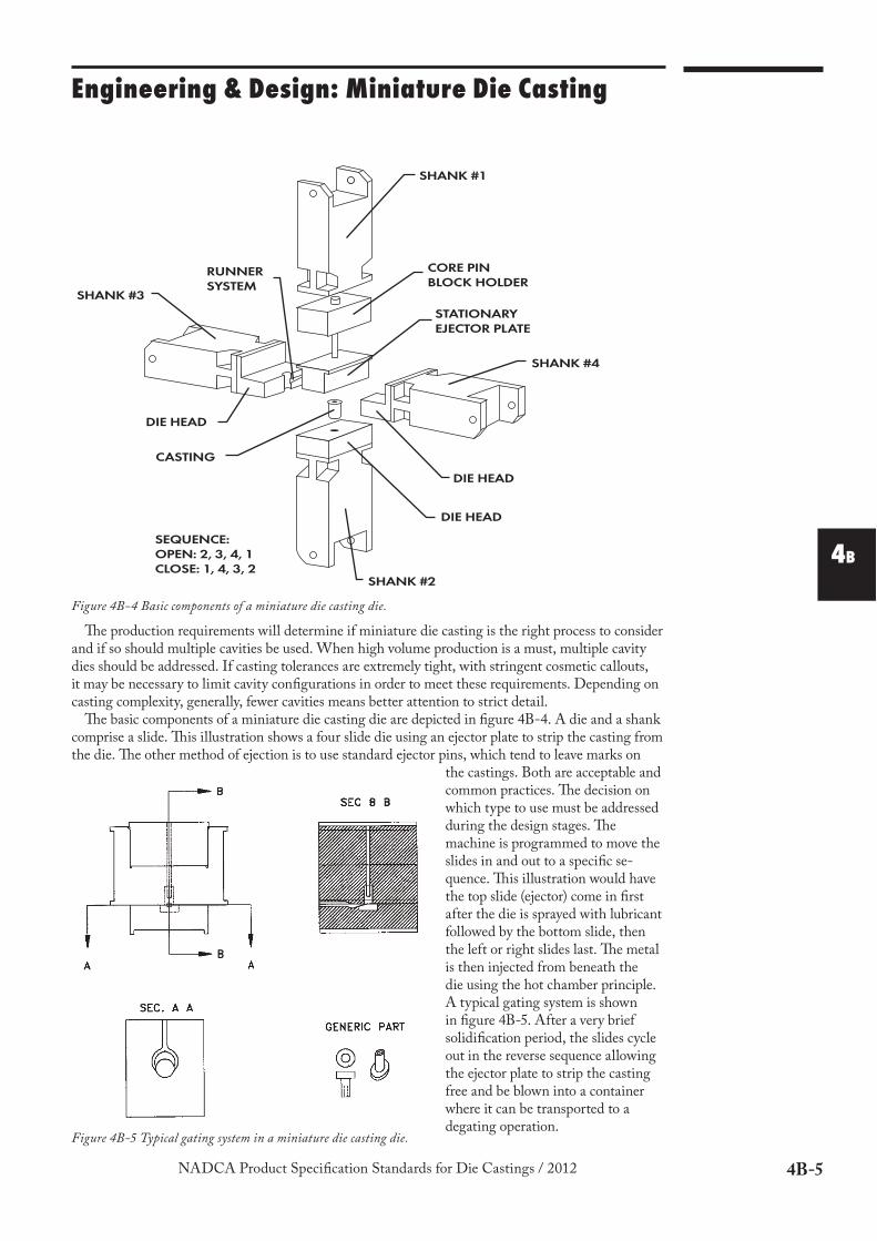
!e basic components of a miniature die casting die are depicted in figure 4B-4. A die and a shank comprise a slide. !is illustration shows a four slide die using an ejector plate to strip the casting from the die. !e other method of ejection is to use standard ejector pins, which tend to leave marks on
the castings. Both are acceptable and common practices. !e decision on which type to use must be addressed during the design stages. !e machine is programmed to move the slides in and out to a specific se-quence. !is illustration would have the top slide (ejector) come in first after the die is sprayed with lubricant followed by the bottom slide, then the left or right slides last. !e metal is then injected from beneath the die using the hot chamber principle. A typical gating system is shown in figure 4B-5. After a very brief solidification period, the slides cycle out in the reverse sequence allowing the ejector plate to strip the casting free and be blown into a container where it can be transported to a degating operation.
SHANK #1
CORE PIN
BLOCK HOLDER
STATIONARY
EJECTOR PLATE
SHANK #4
DIE HEAD
DIE HEAD
SHANK #2
SEQUENCE:
OPEN: 2, 3, 4, 1
CLOSE: 1, 4, 3, 2
CASTING
DIE HEAD
SHANK #3
RUNNER
SYSTEM
Figure 4B-4 Basic components of a miniature die casting die.
Figure 4B-5 Typical gating system in a miniature die casting die.
4B-6 NADCA Product Specification Standards for Die Castings / 2012
Engineering & Design: Miniature Die Casting
COMPONENT MATERIAL HARDNESS
Die T-1 56-58 Rc
Inserts/Subinserts H-13 46-48 Rc
Shank S-7 54-56 Rc
Ejector Plate & Carrier S-7 54-56 Rc
Ejector Pins H-13 65-74 Rc Case Hardened
Core Pins H-13 50-55 Rc Hardened !rough
Crosshead/Frame Gray Cast Iron N/A
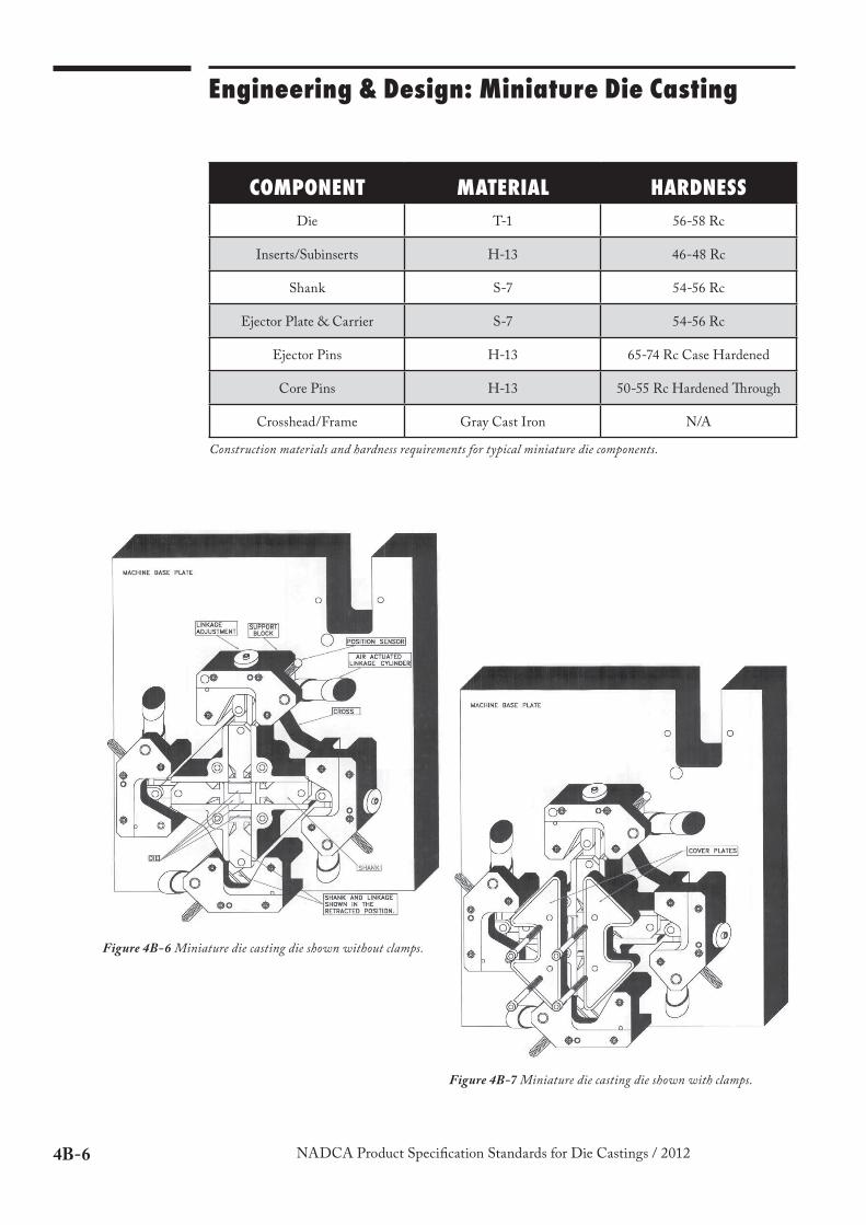
Construction materials and hardness requirements for typical miniature die components.
Figure 4B-7 Miniature die casting die shown with clamps.
Figure 4B-6 Miniature die casting die shown without clamps.

4B-7NADCA Product Specification Standards for Die Castings / 2012
Engineering & Design: Miniature Die Casting
4B
5 Design Consideration for Miniature Die Castings
One of the factors that separate miniature die casting from conventional die casting is the use of tools with fewer cavities. While production costs can be greatly reduced by the use of dies with multiple cavities instead of a single cavity, it must be remembered that the cost of the die increases with each cavity and that some loss of dimensional continuity will probably occur from cavity to cavity. However, because they produce several parts for every casting cycle, multi-cavity dies are practical for designs where quantities are very high.
Both the casting designer and the purchaser will benefit from a basic understanding of the following design hints and by involving your die caster as early as possible. !e experience that he can share with you will help you design a better part at lower cost.
5.1 Weight Reduction
Reducing the volume of material needed to produce a part will reduce material cost. !e more metal the part contains the longer the time required to fill the die cavity and cool the metal prior to ejection, thus adversely affecting run rates. Weight reduction can be achieved by reducing the cross section or by designing pockets. !ese thinner sec-tions can be strengthened if needed with ribs which can also improve metal flow. !e size and location of weight reduction pockets need to be carefully considered as they can sometimes cause irregular shrinkage which may affect accuracy.
5.2 Ribs
Ribs can be added to thin walled castings to increase part strength. In addition, these ribs provide an ideal location for ejector pins and assist in metal flow. Where possible, ribs should be blended with fillets and radii to eliminate sharp corners and rapid changes in cross section.
5.3 Shrinkage
Virtually all metals shrink as they cool to room temperature. With the two most commonly used zinc alloys, #3 and #5, this shrinkage is approximately .007 in. per inch. !is shrinkage, which is always towards the theoretical center, permits the casting to be released from the outside walls of the cavity but tends to lock it onto any die section that projects into it. !is tendency can be reduced by designing “draft” into the part.
5.4 Draft
Draft is the slight taper on the sides of cavity inserts which form any internal features of a die casting. Draft is needed to make it easier for the ejector pins to push the casting out of the cavity. Surfaces of the cavity that have draft are usually highly polished for improved ejection. If no draft is provided the die caster may be forced to use some of the dimen-sional tolerance for draft. However, minimal or no draft is required to push or strip the casting out of the cavity when a stripper is used.
1.0000
0.0350 0.0350
CAVITY
SIZE
CASTING
SIZE
AFTER
SHRINKAGE
DRAFTo
4B-8 NADCA Product Specification Standards for Die Castings / 2012
Engineering & Design: Miniature Die Casting
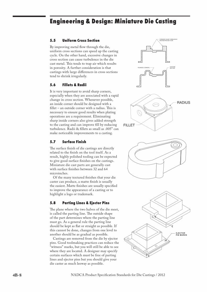
5.5 Uniform Cross Section
By improving metal flow through the die, uniform cross sections can speed up the casting cycle. On the other hand, excessive changes in cross section can cause turbulence in the die cast metal. !is tends to trap air which results in porosity. A further consideration is that castings with large differences in cross sections tend to shrink irregularly.
5.6 Fillets & Radii
It is very important to avoid sharp corners, especially when they are associated with a rapid change in cross section. Whenever possible, an inside corner should be designed with a fillet – an outside corner with a radius. !is is necessary to ensure good results when plating operations are a requirement. Eliminating sharp inside corners also gives added strength to the casting and can improve fill by reducing turbulence. Radii & fillets as small as .005” can make noticeable improvements to a casting.
5.7 Surface Finish
!e surface finish of die castings are directly related to the finish on the tool itself. As a result, highly polished tooling can be expected to give good surface finishes on the castings. Miniature die cast parts are generally cast with surface finishes between 32 and 64 microinches.
Of the many textured finishes that your die caster can produce, a matte finish is usually the easiest. Matte finishes are usually specified to improve the appearance of a casting or to highlight a logo or trademark.
5.8 Parting Lines & Ejector Pins
!e plane where the two halves of the die meet, is called the parting line. !e outside shape of the part determines where the parting line must go. As a general rule the parting line should be kept as flat or straight as possible. If this cannot be done, changes from one level to another should be as gradual as possible.
Castings are removed from the die by ejector pins. Good toolmaking practices can reduce the “witness” marks, but you will still be able to see where they are located. A designer may specify certain surfaces which must be free of parting lines and ejector pins but you should give your die caster as much leeway as possible.
CORNERS CAUSE TURBULENCE
AND RESTRICTED FLOW
ROUNDED CORNERSUNIFORM
SECTION
FILLET
RADIUS
PL
PL
EJECTOR
PIN MARKS
4B-9NADCA Product Specification Standards for Die Castings / 2012
Engineering & Design: Miniature Die Casting
4B
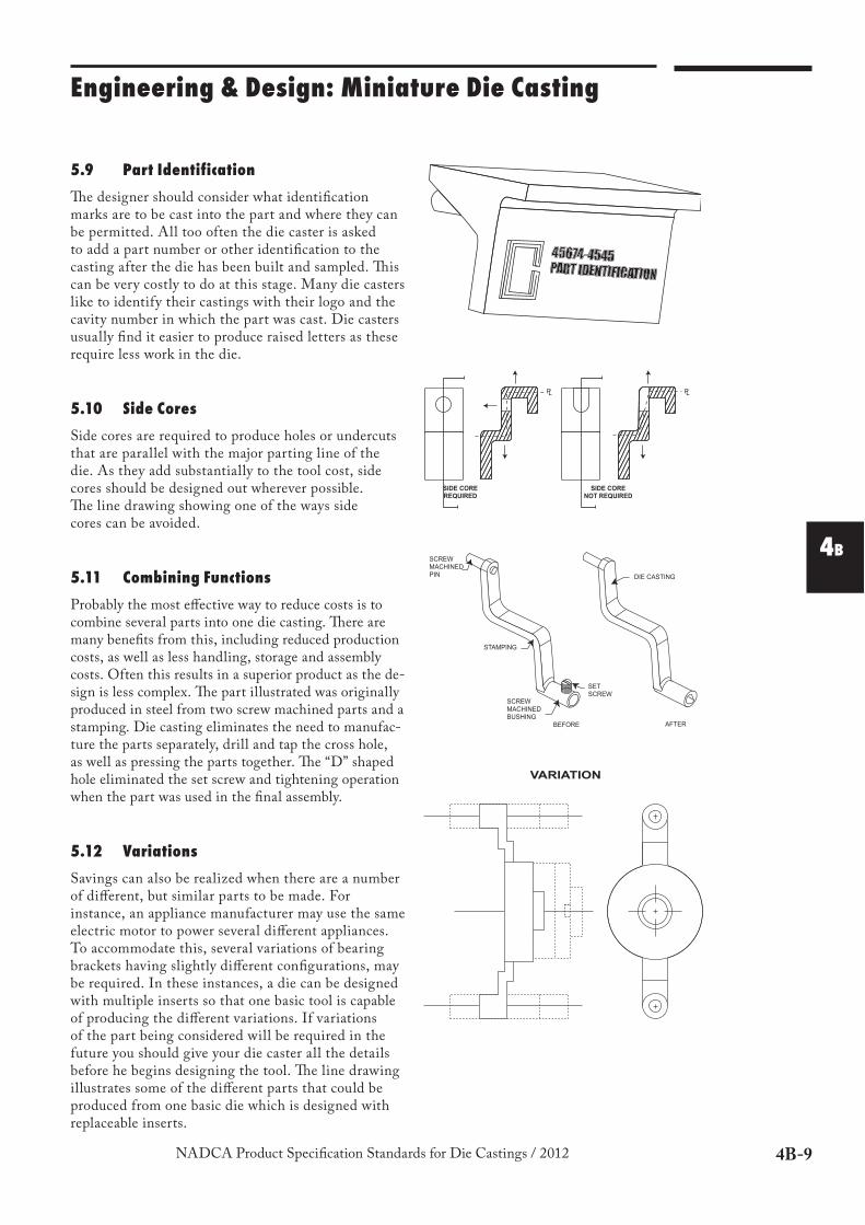
5.9 Part Identification
!e designer should consider what identification marks are to be cast into the part and where they can be permitted. All too often the die caster is asked to add a part number or other identification to the casting after the die has been built and sampled. !is can be very costly to do at this stage. Many die casters like to identify their castings with their logo and the cavity number in which the part was cast. Die casters usually find it easier to produce raised letters as these require less work in the die.
5.10 Side Cores
Side cores are required to produce holes or undercuts that are parallel with the major parting line of the die. As they add substantially to the tool cost, side cores should be designed out wherever possible. !e line drawing showing one of the ways side cores can be avoided.
5.11 Combining Functions
Probably the most effective way to reduce costs is to combine several parts into one die casting. !ere are many benefits from this, including reduced production costs, as well as less handling, storage and assembly costs. Often this results in a superior product as the de-sign is less complex. !e part illustrated was originally produced in steel from two screw machined parts and a stamping. Die casting eliminates the need to manufac-ture the parts separately, drill and tap the cross hole, as well as pressing the parts together. !e “D” shaped hole eliminated the set screw and tightening operation when the part was used in the final assembly.
5.12 Variations
Savings can also be realized when there are a number of different, but similar parts to be made. For instance, an appliance manufacturer may use the same electric motor to power several different appliances. To accommodate this, several variations of bearing brackets having slightly different configurations, may be required. In these instances, a die can be designed with multiple inserts so that one basic tool is capable of producing the different variations. If variations of the part being considered will be required in the future you should give your die caster all the details before he begins designing the tool. !e line drawing illustrates some of the different parts that could be produced from one basic die which is designed with replaceable inserts.
SIDE CORE
REQUIRED
SIDE CORE
NOT REQUIRED
PLPL
DIE CASTING
BEFORE AFTER
SET
SCREW
SCREW
MACHINED
BUSHING
STAMPING
SCREW
MACHINED
PIN
VARIATION
4B-10 NADCA Product Specification Standards for Die Castings / 2012
Engineering & Design: Miniature Die Casting
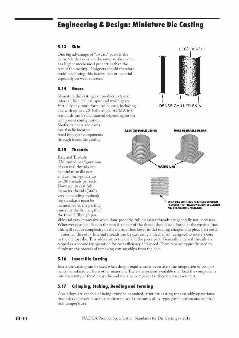
5.13 Skin
One big advantage of “as-cast” parts is the dense “chilled skin” on the outer surface which has higher mechanical properties than the rest of the casting. Designers should therefore avoid machining this harder, denser material especially on wear surfaces.
5.14 Gears
Miniature die casting can produce external, internal, face, helical, spur and worm gears. Virtually any tooth form can be cast, including one with up to a 20° helix angle. AGMA 6-8 standards can be maintained depending on the component configuration. Shafts, ratchets and cams can also be incorpo-rated into gear components through insert die casting.
5.15 Threads
External "reads -Unlimited configurations of external threads can be miniature die cast and can incorporate up to 100 threads per inch. However, to cast full diameter threads (360°) very demanding toolmak-ing standards must be maintained as the parting line runs the full length of the thread. "ough pos-sible and very impressive when done properly, full diameter threads are generally not necessary. Wherever possible, flats to the root diameter of the thread should be allowed at the parting line. "is will reduce complexity in the die and thus lower initial tooling charges and piece part costs.
Internal "reads - Internal threads can be cast using a mechanism designed to rotate a core in the die cast die. "is adds cost to the die and the piece part. Generally internal threads are tapped as a secondary operation for cost efficiency and speed. Form taps are typically used to eliminate the process of removing cutting chips from the hole.
5.16 Insert Die Casting
Insert die casting can be used when design requirements necessitate the integration of compo-nents manufactured from other materials. "ere are systems available that load the components into the cavity of the die cast die and the zinc component is then die cast around it.
5.17 Crimping, Staking, Bending and Forming
Zinc alloys are capable of being crimped or staked, after die casting for assembly operations. Secondary operations are dependent on wall thickness, alloy type, gate location and applica-tion temperature.
4B-11NADCA Product Specification Standards for Die Castings / 2012
Engineering & Design: Miniature Die Casting
4B
6 Available Finishes
Chromates, platings, paints and powder coatings are the most common surface finishes. Chro-mates are conversion coatings applied through electro-chemical treatments to improve corrosion resistance. !ese treatments convert the metal surface to a superficial layer containing a mixture of chromium compounds of various colors and resistance.
Chromated components are corrosion tested in a 5% continuous salt spray environment as outlined in ASTM standard B117. !e following colors exhibit the varying performances; olive drab – 96 hours of protection, bright yellow – 48 hours of protection and clear – 24 hours of protection.
Platings are applied to small zinc components for aesthetic purposes, and to improve corrosion resistance, conductivity, hardness, wear resistance and solderability. !e most common applied platings are: Nickel, Brass, Tin, Copper, Silver and Gold.
Paints are used primarily for decoration, protection, identification, concealing surface irregu-larities or for increasing/decreasing surface friction.
Powder coatings provide a protective and attractive finish to components. !ey cover evenly, have the ability to conceal surface imperfections, and provide good corrosion resistance.
For more information on finishes and coatings, see Section 6.
7 Castable Zinc Alloys
Zinc alloys are used in the production of small components because they are versatile, depend-able, cost effective materials which can be used in an unlimited range of applications. As pre-cisely formulated metal alloys, they offer the mechanical properties of medium strength metals.
!e most commonly used zinc alloys in miniature die casting are #2, #3, #5, #7 and ZA-8. !ese alloys offer higher tensile strengths than most aluminum and magnesium alloys, higher yield strengths, greater impact resistance, higher Brinell hardness and better ductility.
Zinc alloys facilitate higher die casting cycle speeds versus aluminum and magnesium, more complex shapes, thinner wall sections, smoother surface finishes, and higher standards of dimensional accuracy.
Compared to plastic, zinc alloys are generally several times stronger and many times more rigid. !eir mechanical properties compare favorably with powdered iron, brass and screw-machined steel.
4B-12 NADCA Product Specification Standards for Die Castings / 2012
Engineering & Design: Miniature Die Casting
8 Glossary of Miniature Die Casting Terminology
Tumble Degating A process commonly used in miniature die casting to remove the feeder system and any excess flash around the parting line of cast-ings. Vibration can be introduced or simply the effect of castings tumbling into each other in a controlled container will remove the unwanted burrs and flash from the castings.
Slide Portion of die which moves, usually perpendicular or parallel to the parting line. Typically comprised of the die and shank.
Four-Slide A type of die configuration very common to miniature die castings utilizing four moving sections to form the cavity detail.
Multiple-Slide A miniature die casting die utilizing two or more moving die components to form the cavity detail.
Die Also called slide head or cavity insert, these are the detailed components of the miniature die casting die that move together in a critically timed sequence to form the cavity.
Metal Pressure "e pounds per square inch of pressure found inside the cavity that is derived from the cross sectional area of the shot cylinder times the shot pressure divided by the cross sectional area of the inlet feeder.
Die Lock Up Force "e amount of force applied to the dies necessary to overcome the metal pressure and prevent the dies from opening during the injection of metal.
Shank "e carrier portion of the slide assembly which moves within the crosshead.
Core A part of the die casting die that forms an internal feature of the casting and is a separate piece from the cavity block. A core may be incorporated into the die heads or top and bottom shanks. Almost always made with proper draft for ease of removal from the internal features of the casting.
Cross-Head Housing that supports and aligns up to four shanks.