Embed Size (px)
Citation preview

DatasheetSelf-contained photoelectric sensors
• 10 to 30 V DC with bipolar NPN/PNP outputs• Signal strength or output indicator• 2 m or 9 m integral cable, or Euro-style quick-disconnect fitting• 18 mm threaded lens mount on some models
WARNING:• Do not use this device for personnel protection• Using this device for personnel protection could result in serious injury or death.• This device does not include the self-checking redundant circuitry necessary to allow its use in
personnel safety applications. A device failure or malfunction can cause either an energized (on) or de-energized (off) output condition.
ModelsIntegral 2 m (6.5 ft) unterminated cable models are listed.
• To order the 9 m (30 ft) PVC cable model, add the suffix "W/30" to the cabled model number. For example, SM31EW/30.• To order the 4-pin M12/Euro-style QD models, add the suffix “QD” to the model number. For example, SM31EQD.• To order the 150 mm (6 in) cable with QD, add the suffix “QDP” to the model number. For example, SM31EQDP.• To order a 0.3 ms response time model, add the suffix “MHS” to the model number. For example, SM31EMHS.
Sensing Mode Range LED Model
OPPOSED
Opposed Emitter3 m (10 ft)
Infrared, 880 nm
SM31E
Opposed Receiver SM31R
Opposed Emitter - Long Range30 m (100 ft)
SM31EL
Opposed Receiver - Long Range SM31RL
OPPOSED
Opposed Emitter - Clear Plastic Detection 0 to 300 mm (0 to 12 in) Actual range varies,depending on the light transmissionproperties of the plastic material beingsensed.
Visible red, 650 nm
SM31EPD
Opposed Receiver - Clear Plastic Detection SM31RPD
RETRO
Non-Polarized Retroreflective 5 m (15 ft) SM312LV
PPOLAR RETRO
Polarized Retroreflective 55 mm to 2 m (2 in to 7 ft) SM312LVAG
Extended-Range Polarized Retroreflective 10 mm to 3 m (0.4 in to 10 ft) SM312LP
DIFFUSE
Diffuse380 mm (15 in)
Infrared, 880 nm
SM312D
300 mm (12 in) SM312DBZ
Divergent Diffuse 130 mm (5 in) SM312W
CONVERGENT
Convergent
16 mm (0.65 in) Focus SM312C
43 mm (1.7 in) Focus SM312C2
MINI-BEAM® DC Voltage Series Sensor
Original Document69943 Rev. G
8 September 2020
69943
Sensing Mode Range LED Model
CONVERGENT
16 mm (0.65 in) Focus
Visible red, 650 nm
SM312CV
43 mm (1.7 in) Focus SM312CV2
CONVERGENT
16 mm (0.65 in) Focus
Visible blue, 475 nm
SM312CVB
49 mm (1.9 in) Focus SM312CV2B
CONVERGENT
16 mm (0.65 in) Focus
Visible green, 525 nm
SM312CVG
49 mm (1.9 in) Focus SM312CV2G
GLASS FIBER
Glass Fiber Optic
Range varies, depending on sensing modeand fiber optics used.
Infrared, 880 nm SM312F
Visible red, 650 nm SM312FV
Visible blue, 475 nm SM312FVB
Visible green, 525 nm SM312FVG
PLASTIC FIBER
Plastic Fiber Optic
Visible red, 650 nm SM312FP
Visible blue, 475 nm SM312FPB
Visible green, 525 nm SM312FPG
Special High-Power Option Plastic FiberOptic
Visible red, 650 nm SM312FPH
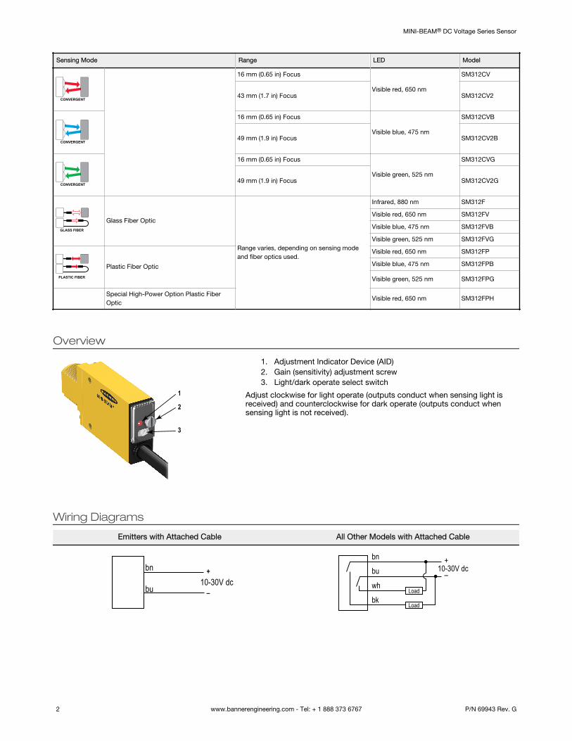
Overview
1
2
3
1. Adjustment Indicator Device (AID)2. Gain (sensitivity) adjustment screw3. Light/dark operate select switch
Adjust clockwise for light operate (outputs conduct when sensing light isreceived) and counterclockwise for dark operate (outputs conduct whensensing light is not received).
Wiring Diagrams
Emitters with Attached Cable All Other Models with Attached Cable
bn
bu
+
–10-30V dc
bn
wh
bu+
–
bkLoad
Load
10-30V dc
MINI-BEAM® DC Voltage Series Sensor
2 www.bannerengineering.com - Tel: + 1 888 373 6767 P/N 69943 Rev. G
Emitters with Quick Disconnect (4-pin Euro-Style) All Other Models with Quick Disconnect (4-pin Euro-Style)
bn
wh
bu+
–
bk
10-30V dcbn
wh
bu+
–
bkLoad
Load
10-30V dc
The output type for all models is Bipolar NPN/PNP; load 150 mA max., each output.
Sensor Mounting and AlignmentMINI-BEAM sensors perform most reliably if they are properly aligned and securely mounted.
For maximum mechanical stability, mount MINI-BEAM sensors through 18 mm diameter holes by their threaded barrel (whereavailable), or use a mounting bracket. A complete selection of mounting brackets is available. Visit http://www.bannerengineering.com or contact Banner Engineering for information on mounting options.
Begin with line-of-sight positioning of the MINI-BEAM sensor to its emitter (opposed-mode sensing) or to its target (all othersensing modes). When using a retroreflective sensor, the target is the retroreflector (“retro target”). For diffuse or convergentsensing modes, the target is the object to be detected.
Apply power to the sensor (and to the emitter, if using the opposed mode). Advance the 15-turn Gain control to maximum(clockwise end of rotation) using a small flat-blade screwdriver. The Gain control is clutched at both ends to avoid damage and will“free-wheel” when either endpoint is reached.
If the MINI-BEAM sensor is receiving its light signal, the red LED Alignment indicator will be ON and flashing at a rate proportionalto the signal strength (faster = more signal). Move the sensor (or retro target, if applicable) up-down-right-left (including angularrotation) to find the center of the movement zone within which the LED indicator remains ON. Reducing the Gain setting reducesthe size of the movement zone for more precise alignment.
Repeat the alignment motions after each Gain reduction. When optimum alignment is achieved, mount sensor(s) (and the retrotarget, if applicable) solidly in that position. Increase the Gain to maximum.
Test the sensor by placing the object to be detected in the sensing position, then removing it. The Alignment indicator LED shouldcome ON when the sensing beam is established (Light condition) or be ON when the beam is broken (Dark condition). If theAlignment indicator LED stays ON for both sensing conditions, consider the following tips for each sensing mode.
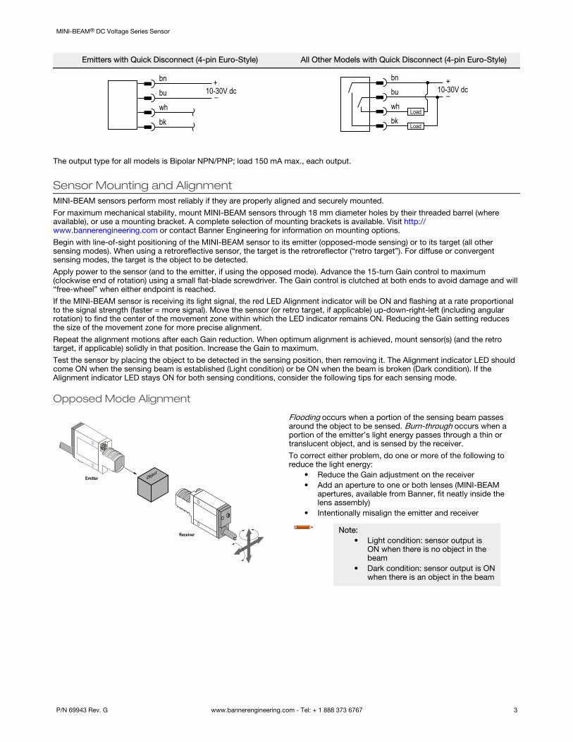
Opposed Mode Alignment
ObjectEmitter
Receiver
Flooding occurs when a portion of the sensing beam passesaround the object to be sensed. Burn-through occurs when aportion of the emitter’s light energy passes through a thin ortranslucent object, and is sensed by the receiver.
To correct either problem, do one or more of the following toreduce the light energy:
• Reduce the Gain adjustment on the receiver• Add an aperture to one or both lenses (MINI-BEAM
apertures, available from Banner, fit neatly inside thelens assembly)
• Intentionally misalign the emitter and receiver
Note:• Light condition: sensor output is
ON when there is no object in thebeam
• Dark condition: sensor output is ONwhen there is an object in the beam
MINI-BEAM® DC Voltage Series Sensor
P/N 69943 Rev. G www.bannerengineering.com - Tel: + 1 888 373 6767 3

Diffuse Mode Alignment
Object
If the Alignment LED does not go OFF when the object isremoved from the beam, the sensor is probably detecting lightreflected from some background object. To remedy thisproblem:
• Reduce the reflectivity of the background by paintingthe surface(s) flat-black, scuffing any shiny surface, ordrilling a large hole, directly opposite the diffuse sensor
• Move the sensor closer to the object to be detected andreduce the Gain adjustment. Rule of thumb for diffusesensing: The distance to the nearest background objectshould be at least three times the sensing distance
Note:• Light condition: sensor output is
ON when there is no object in thebeam
• Dark condition: sensor output is ONwhen there is an object in the beam
Retroreflective Mode Alignment
Retro
Target
A highly reflective object may reflect enough light back to aretroreflective sensor to allow that object to slip through thebeam, without being detected. This problem is called proxing,and the following methods may be used to correct it:
• Position the sensor and retro target so the beam will notstrike a shiny surface perpendicular to the sensor lens
• Reduce the Gain adjustment• Add a polarizing filter (for model SM312LV)
Note:• Light condition: sensor output is
ON when there is no object in thebeam
• Dark condition: sensor output is ONwhen there is an object in the beam
Convergent Mode Alignment
Object
Low
Reflectivity
Background
The sensing energy of a convergent mode sensor isconcentrated at the specified focus point. Convergent modesensors are less sensitive to background reflections, comparedwith diffuse mode sensors. However, if background reflectionsare a problem:
• Skew the sensor position at a 10° to 25° angle toeliminate direct reflections from shiny backgroundsurfaces
• Reduce the reflectivity of the background by paintingthe surface(s) flat-black, scuffing any shiny surface, ordrilling a large hole, directly opposite the sensor
• Reduce the Gain adjustment
Note:• Light condition: sensor output is
ON when there is no object in thebeam
• Dark condition: sensor output is ONwhen there is an object in the beam
MINI-BEAM® DC Voltage Series Sensor
4 www.bannerengineering.com - Tel: + 1 888 373 6767 P/N 69943 Rev. G
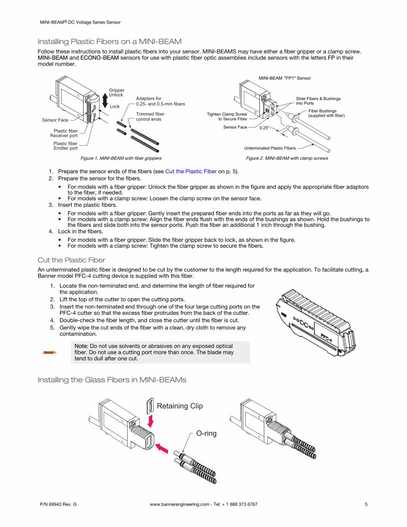
Installing Plastic Fibers on a MINI-BEAMFollow these instructions to install plastic fibers into your sensor. MINI-BEAMS may have either a fiber gripper or a clamp screw.MINI-BEAM and ECONO-BEAM sensors for use with plastic fiber optic assemblies include sensors with the letters FP in theirmodel number.
Trimmed fibercontrol ends
Plastic fiberEmitter port
Plastic fiberReceiver port
GripperUnlock
Lock
Adapters for0.25- and 0.5-mm fibers
Sensor Face
Figure 1. MINI-BEAM with fiber grippers
Slide Fibers & Bushingsinto Ports
Fiber Bushings(supplied with fiber)
MINI-BEAM "FP1" Sensor
Unterminated Plastic Fibers
Sensor Face
Tighten Clamp Screwto Secure Fiber
0.25"
Figure 2. MINI-BEAM with clamp screws
1. Prepare the sensor ends of the fibers (see Cut the Plastic Fiber on p. 5).2. Prepare the sensor for the fibers.
• For models with a fiber gripper: Unlock the fiber gripper as shown in the figure and apply the appropriate fiber adaptorsto the fiber, if needed.
• For models with a clamp screw: Loosen the clamp screw on the sensor face.3. Insert the plastic fibers.
• For models with a fiber gripper: Gently insert the prepared fiber ends into the ports as far as they will go.• For models with a clamp screw: Align the fiber ends flush with the ends of the bushings as shown. Hold the bushings to
the fibers and slide both into the sensor ports. Push the fiber an additional 1 inch through the bushing.4. Lock in the fibers.
• For models with a fiber gripper: Slide the fiber gripper back to lock, as shown in the figure.• For models with a clamp screw: Tighten the clamp screw to secure the fibers.
Cut the Plastic FiberAn unterminated plastic fiber is designed to be cut by the customer to the length required for the application. To facilitate cutting, aBanner model PFC-4 cutting device is supplied with this fiber.
1. Locate the non-terminated end, and determine the length of fiber required forthe application.
2. Lift the top of the cutter to open the cutting ports.3. Insert the non-terminated end through one of the four large cutting ports on the
PFC-4 cutter so that the excess fiber protrudes from the back of the cutter.4. Double-check the fiber length, and close the cutter until the fiber is cut.5. Gently wipe the cut ends of the fiber with a clean, dry cloth to remove any
contamination.
Note: Do not use solvents or abrasives on any exposed opticalfiber. Do not use a cutting port more than once. The blade maytend to dull after one cut.
Installing the Glass Fibers in MINI-BEAMs
O-ring
Retaining Clip
MINI-BEAM® DC Voltage Series Sensor
P/N 69943 Rev. G www.bannerengineering.com - Tel: + 1 888 373 6767 5
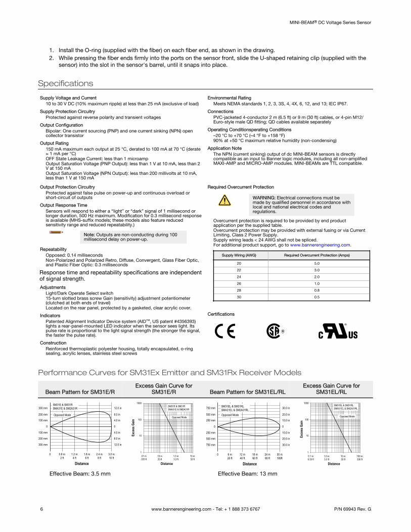
1. Install the O-ring (supplied with the fiber) on each fiber end, as shown in the drawing.2. While pressing the fiber ends firmly into the ports on the sensor front, slide the U-shaped retaining clip (supplied with the
sensor) into the slot in the sensor's barrel, until it snaps into place.
Specifications
Supply Voltage and Current10 to 30 V DC (10% maximum ripple) at less than 25 mA (exclusive of load)
Supply Protection CircuitryProtected against reverse polarity and transient voltages
Output ConfigurationBipolar: One current sourcing (PNP) and one current sinking (NPN) opencollector transistor
Output Rating150 mA maximum each output at 25 °C, derated to 100 mA at 70 °C (derate≈ 1 mA per °C)OFF State Leakage Current: less than 1 microampOutput Saturation Voltage (PNP Output): less than 1 V at 10 mA, less than 2V at 150 mAOutput Saturation Voltage (NPN Output): less than 200 millivolts at 10 mA,less than 1 V at 150 mA
Environmental RatingMeets NEMA standards 1, 2, 3, 3S, 4, 4X, 6, 12, and 13; IEC IP67.
ConnectionsPVC-jacketed 4-conductor 2 m (6.5 ft) or 9 m (30 ft) cables, or 4-pin M12/Euro-style male QD fitting; QD cables available separately
Operating Conditionsperating Conditions–20 °C to +70 °C (–4 °F to +158 °F)90% at +50 °C maximum relative humidity (non-condensing)
Application NoteThe NPN (current sinking) output of dc MINI-BEAM sensors is directlycompatible as an input to Banner logic modules, including all non-amplifiedMAXI-AMP and MICRO-AMP modules. MINI-BEAMs are TTL compatible.
Output Protection CircuitryProtected against false pulse on power-up and continuous overload orshort-circuit of outputs
Output Response TimeSensors will respond to either a “light” or “dark” signal of 1 millisecond orlonger duration, 500 Hz maximum. Modification for 0.3 millisecond responseis available (MHS-suffix models; these models also feature reducedsensitivity range and reduced repeatability.)
Note: Outputs are non-conducting during 100millisecond delay on power-up.
RepeatabilityOpposed: 0.14 millisecondsNon-Polarized and Polarized Retro, Diffuse, Convergent, Glass Fiber Optic,and Plastic Fiber Optic: 0.3 milliseconds
Response time and repeatability specifications are independentof signal strength.Adjustments
Light/Dark Operate Select switch15-turn slotted brass screw Gain (sensitivity) adjustment potentiometer(clutched at both ends of travel)Located on the rear panel, protected by a gasketed, clear acrylic cover.
IndicatorsPatented Alignment Indicator Device system (AID™, US patent #4356393)lights a rear-panel-mounted LED indicator when the sensor sees light. Itspulse rate is proportional to the light signal strength (the stronger the signal,the faster the pulse rate).
ConstructionReinforced thermoplastic polyester housing, totally encapsulated, o-ringsealing, acrylic lenses, stainless steel screws
Required Overcurrent Protection
WARNING: Electrical connections must bemade by qualified personnel in accordance withlocal and national electrical codes andregulations.
Overcurrent protection is required to be provided by end productapplication per the supplied table.Overcurrent protection may be provided with external fusing or via CurrentLimiting, Class 2 Power Supply.Supply wiring leads < 24 AWG shall not be spliced.For additional product support, go to www.bannerengineering.com.
Supply Wiring (AWG) Required Overcurrent Protection (Amps)
20 5.0
22 3.0
24 2.0
26 1.0
28 0.8
30 0.5
Certifications
Performance Curves for SM31Ex Emitter and SM31Rx Receiver Models
Beam Pattern for SM31E/RExcess Gain Curve for
SM31E/R Beam Pattern for SM31EL/RLExcess Gain Curve for
SM31EL/RL
3.0 m10 ft
2.4 m8 ft
1.8 m6 ft
1.2 m4 ft
0.6 m2 ft
0
0
100 mm
200 mm
300 mm
100 mm
200 mm
300 mm
0
4.0 in
8.0 in
12.0 in
4.0 in
8.0 in
12.0 in
Distance
Opposed Mode
SM31E & SM31RSMA31E & SM2A31R
1
10
100
.10 m.33 ft
1.0 m3.3 ft
10 m33 ft
.01 m.033 ft
Distance
1000
Exce
ss G
ain
Opposed Mode
SM31E & SM31RSMA31E & SM2A31R
30 m100ft
24 m80 ft
18 m60 ft
12 m40 ft
6 m20 ft
0
0
250 mm
500 mm
750 mm
250 mm
500 mm
750 mm
0
10.0 in
20.0 in
30.0 in
10.0 in
20.0 in
30.0 in
Distance
Opposed Mode
SM31EL & SM31RLSMA31EL & SM2A31RL
1
10
100
1.0 m3.3 ft
10 m33 ft
100 m330 ft
0.1 m0.33 ft
1000
Distance
Opposed Mode
Exce
ss G
ain
SM31EL & SM31RLSMA31EL & SM2A31RL
Effective Beam: 3.5 mm Effective Beam: 13 mm
MINI-BEAM® DC Voltage Series Sensor
6 www.bannerengineering.com - Tel: + 1 888 373 6767 P/N 69943 Rev. G
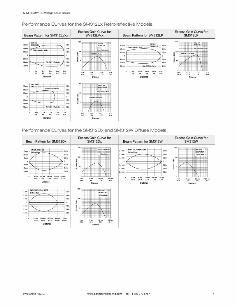
Performance Curves for the SM312Lx Retroreflective Models
Beam Pattern for SM312LVxxExcess Gain Curve for
SM312LVxx Beam Pattern for SM312LPExcess Gain Curve for
SM312LP
5 m15 ft
4 m12 ft
3 m9 ft
2 m6 ft
1 m3 ft
0
0
25 mm
50 mm
75 mm
25 mm
50 mm
75 mm
0
1.0 in
2.0 in
3.0 in
1.0 in
2.0 in
3.0 in
Distance
Retroreflective Mode
SM312LVSM2A312LV
With BRT-3 Reflector
1
10
100
1000
.10 m.33 ft
1.0 m3.3 ft
10 m33 ft
.01 m.033 ft
DistanceEx
cess
Gain
Retroreflective Mode
With BRT-3 Reflector
SM312LVSM2A312LV
3.0 m20 ft
2.4 m8 ft
1.8 m6 ft
1.2 m4 ft
.6 m2 ft
0
0
20 mm
40 mm
60 mm
20 mm
40 mm
60 mm
0
0.8 in
1.6 in
2.4 in
0.8 in
1.6 in
2.4 in
Distance
Retroreflective ModeSM312LPSM2A312LP
With BRT-3 Reflector
1
10
100
0.1 m0.3 ft
1 m3 ft
10 m30 ft
.01 m0.03 ft
1000
Distance
Exce
ss G
ain
Retroreflective Mode
SM312LPSM2A312LP
With BRT-3 Reflector
3.0 m10 ft
2.4 m8 ft
1.8 m6 ft
1.2 m4 ft
.6 m2 ft
0
0
25 mm
50 mm
75 mm
25 mm
50 mm
75 mm
0
1.0 in
2.0 in
3.0 in
1.0 in
2.0 in
3.0 in
Distance
Retroreflective Mode
SM312LVAGSM2A312LVAG
With BRT-3 Reflector
1
10
100
.10 m.33 ft
1.0 m3.3 ft
10 m33 ft
.01 m.033 ft
1000
Distance
Exce
ss G
ain
Retroreflective Mode
With BRT-3 Reflector
SM312LVAGSM2A312LVAG
Performance Curves for the SM312Dx and SM312W Diffuse Models
Beam Pattern for SM312DxExcess Gain Curve for
SM312Dx Beam Pattern for SM312WExcess Gain Curve for
SM312W
375 mm15.0 in
300 mm12.0 in
225 mm9.0 in
150 mm6.0 in
75 mm3.0 in
0
0
5 mm
10 mm
15 mm
5 mm
10 mm
15 mm
0
0.2 in
0.4 in
0.6 in
0.2 in
0.4 in
0.6 in
Distance
Diffuse ModeSM312D, SM2A312D
1
10
100
10 mm.4 in
100 mm4 in
1000 mm40 in
1 mm.04 in
1000
Distance
Diffuse Mode
Exce
ss G
ain
SM312D, SM2A312D
125 mm5.0 in
100 mm4.0 in
75 mm3.0 in
50 mm2.0 in
25 mm1.0 in
0
0
7.5 mm
15.0 mm
22.5 mm
7.5 mm
15.0 mm
22.5 mm
0
0.3 in
0.6 in
0.9 in
0.3 in
0.6 in
0.9 in
Distance
Diffuse ModeSM312W, SM2A312W
1
10
100
10 mm.4 in
100 mm4 in
1000 mm40 in
1 mm.04 in
1000
Distance
Exce
ss G
ain
Diffuse Mode
SM312WSM2A312W
375 mm15.0 in
300 mm12.0 in
225 mm9.0 in
150 mm6.0 in
75 mm3.0 in
0
0
5 mm
10 mm
15 mm
5 mm
10 mm
15 mm
0
0.2 in
0.4 in
0.6 in
0.2 in
0.4 in
0.6 in
Distance
Diffuse ModeSM312DBZ, SM2A312DBZ
1
10
100
10 mm.40 in
100 mm4.0 in
1000 mm40 in
1 mm.04 in
1000
Distance
Exce
ss G
ain
Diffuse Mode
SM312DBZSM2A312DBZ
MINI-BEAM® DC Voltage Series Sensor
P/N 69943 Rev. G www.bannerengineering.com - Tel: + 1 888 373 6767 7
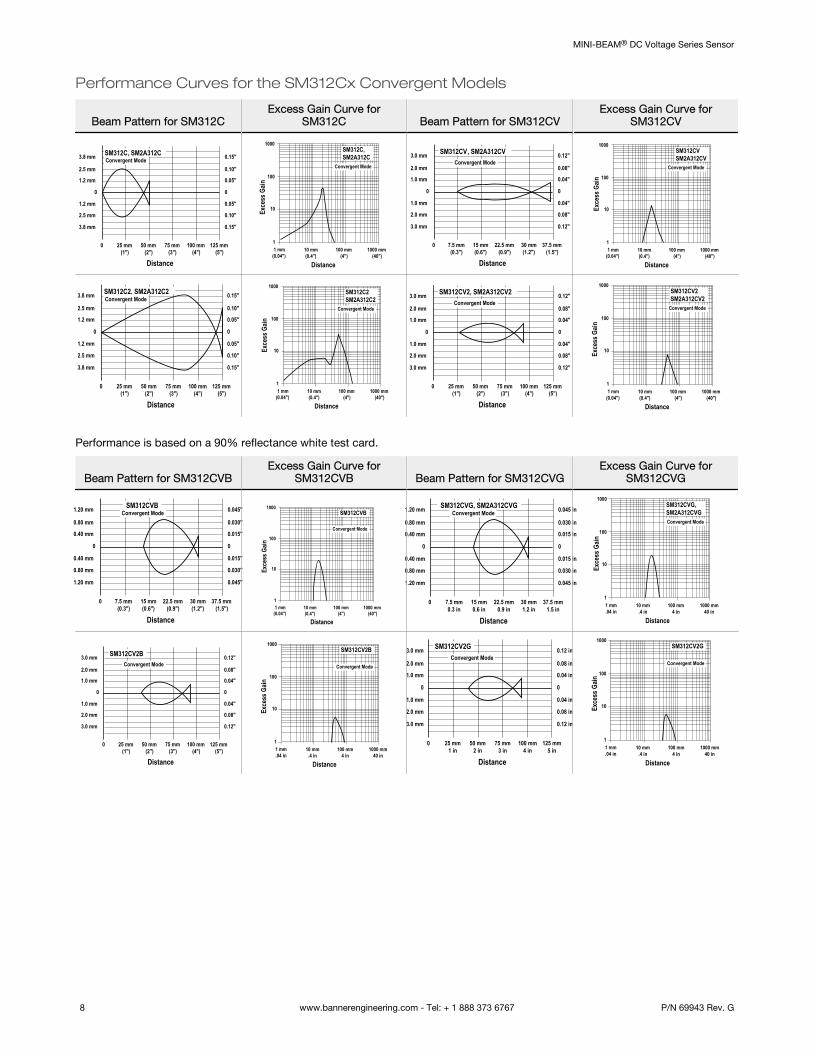
Performance Curves for the SM312Cx Convergent Models
Beam Pattern for SM312CExcess Gain Curve for
SM312C Beam Pattern for SM312CVExcess Gain Curve for
SM312CV
125 mm(5")
100 mm(4")
75 mm(3")
50 mm(2")
25 mm(1")
0
0
1.2 mm
2.5 mm
3.8 mm
1.2 mm
2.5 mm
3.8 mm
0
0.05"
0.10"
0.15"
0.05"
0.10"
0.15"
Distance
SM312C, SM2A312CConvergent Mode
1
10
100
10 mm(0.4")
100 mm(4")
1000 mm(40")
1 mm(0.04")
1000
Distance
SM312C,SM2A312C
Convergent Mode
Exce
ss G
ain
37.5 mm(1.5")
30 mm(1.2")
22.5 mm(0.9")
15 mm(0.6")
7.5 mm(0.3")
0
0
1.0 mm
2.0 mm
3.0 mm
1.0 mm
2.0 mm
3.0 mm
0
0.04"
0.08"
0.12"
0.04"
0.08"
0.12"
Distance
SM312CV, SM2A312CVConvergent Mode
1
10
100
10 mm(0.4")
100 mm(4")
1000 mm(40")
1 mm(0.04")
1000
Distance
SM312CVSM2A312CV
Convergent Mode
Exce
ss G
ain
125 mm(5")
100 mm(4")
75 mm(3")
50 mm(2")
25 mm(1")
0
0
1.2 mm
2.5 mm
3.8 mm
1.2 mm
2.5 mm
3.8 mm
0
0.05"
0.10"
0.15"
0.05"
0.10"
0.15"
Distance
SM312C2, SM2A312C2Convergent Mode
1
10
100
10 mm(0.4")
100 mm(4")
1000 mm(40")
1 mm(0.04")
1000
Distance
SM312C2SM2A312C2
Convergent Mode
Exce
ss G
ain
125 mm(5")
100 mm(4")
75 mm(3")
50 mm(2")
25 mm(1")
0
0
1.0 mm
2.0 mm
3.0 mm
1.0 mm
2.0 mm
3.0 mm
0
0.04"
0.08"
0.12"
0.04"
0.08"
0.12"
Distance
SM312CV2, SM2A312CV2Convergent Mode
1
10
100
10 mm(0.4")
100 mm(4")
1000 mm(40")
1 mm(0.04")
1000
Distance
SM312CV2SM2A312CV2
Convergent Mode
Exce
ss G
ain
Performance is based on a 90% reflectance white test card.
Beam Pattern for SM312CVBExcess Gain Curve for
SM312CVB Beam Pattern for SM312CVGExcess Gain Curve for
SM312CVG
37.5 mm(1.5")
30 mm(1.2")
22.5 mm(0.9")
15 mm(0.6")
7.5 mm(0.3")
0
0
0.40 mm
0.80 mm
1.20 mm
0.40 mm
0.80 mm
1.20 mm
0
0.015"
0.030"
0.045"
0.015"
0.030"
0.045"
Distance
SM312CVBConvergent Mode
1
10
100
10 mm(0.4")
100 mm(4")
1000 mm(40")
1 mm(0.04")
1000
Distance
SM312CVB
Convergent Mode
Exce
ss G
ain
37.5 mm1.5 in
30 mm1.2 in
22.5 mm0.9 in
15 mm0.6 in
7.5 mm0.3 in
0
0
0.40 mm
0.80 mm
1.20 mm
0.40 mm
0.80 mm
1.20 mm
0
0.015 in
0.030 in
0.045 in
0.015 in
0.030 in
0.045 in
Distance
SM312CVG, SM2A312CVGConvergent Mode
1
10
100
10 mm.4 in
100 mm4 in
1000 mm40 in
1 mm.04 in
1000
Distance
Exce
ss G
ain
SM312CVG,SM2A312CVGConvergent Mode
125 mm(5")
100 mm(4")
75 mm(3")
50 mm(2")
25 mm(1")
0
0
1.0 mm
2.0 mm
3.0 mm
1.0 mm
2.0 mm
3.0 mm
0
0.04"
0.08"
0.12"
0.04"
0.08"
0.12"
Distance
SM312CV2BConvergent Mode
1
10
100
10 mm.4 in
100 mm4 in
1000 mm40 in
1 mm.04 in
1000
Distance
SM312CV2B
Convergent Mode
Exce
ss G
ain
125 mm5 in
100 mm4 in
75 mm3 in
50 mm2 in
25 mm1 in
0
0
1.0 mm
2.0 mm
3.0 mm
1.0 mm
2.0 mm
3.0 mm
0
0.04 in
0.08 in
0.12 in
0.04 in
0.08 in
0.12 in
Distance
SM312CV2GConvergent Mode
1
10
100
10 mm.4 in
100 mm4 in
1000 mm40 in
1 mm.04 in
1000
Distance
Exce
ss G
ain
SM312CV2G
Convergent Mode
MINI-BEAM® DC Voltage Series Sensor
8 www.bannerengineering.com - Tel: + 1 888 373 6767 P/N 69943 Rev. G
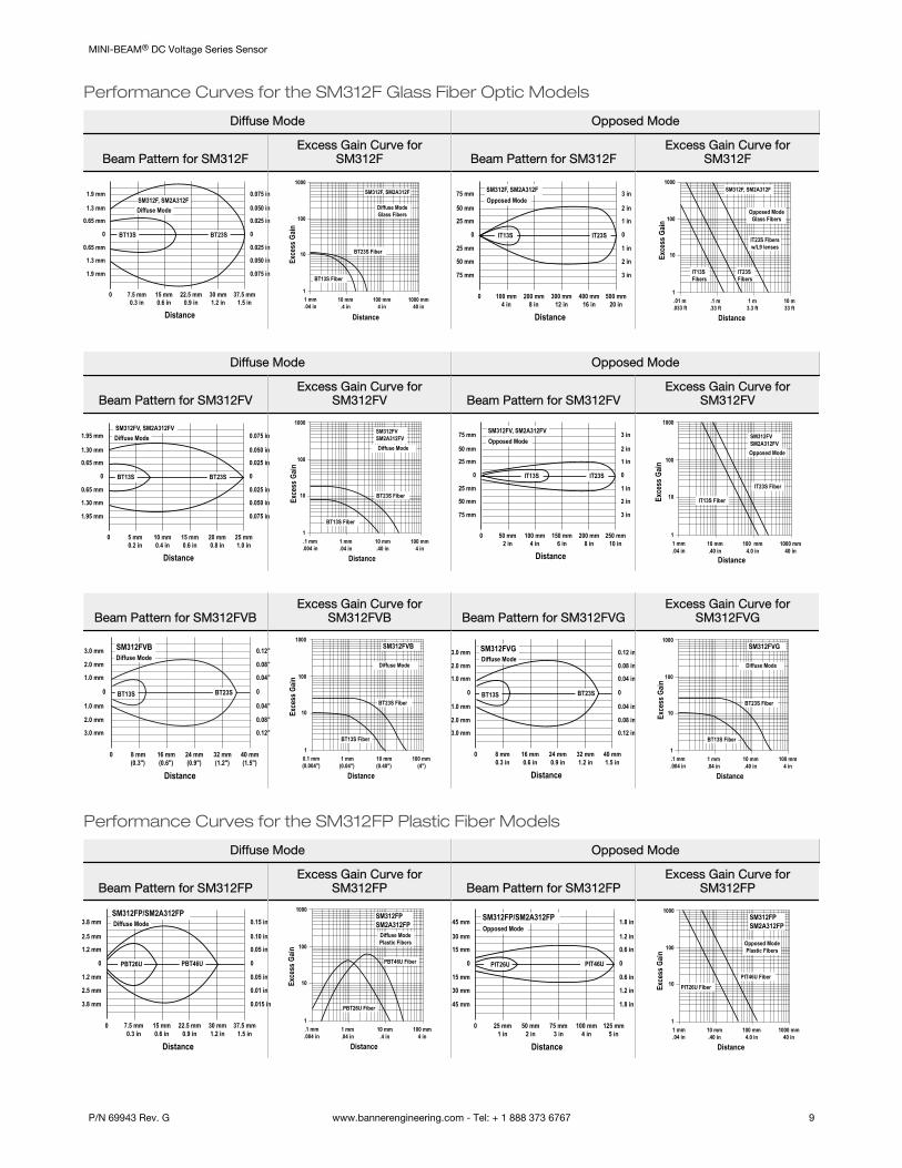
Performance Curves for the SM312F Glass Fiber Optic Models
Diffuse Mode Opposed Mode
Beam Pattern for SM312FExcess Gain Curve for
SM312F Beam Pattern for SM312FExcess Gain Curve for
SM312F
37.5 mm1.5 in
30 mm1.2 in
22.5 mm0.9 in
15 mm0.6 in
7.5 mm0.3 in
0
0
0.65 mm
1.3 mm
1.9 mm
0.65 mm
1.3 mm
1.9 mm
0
0.025 in
0.050 in
0.075 in
0.025 in
0.050 in
0.075 in
Distance
Diffuse Mode
BT23SBT13S
SM312F, SM2A312F
1
10
100
10 mm.4 in
100 mm4 in
1000 mm40 in
1 mm.04 in
1000
Distance
Exce
ss G
ain
Diffuse ModeGlass Fibers
BT23S Fiber
BT13S Fiber
SM312F, SM2A312F
500 mm20 in
400 mm16 in
300 mm12 in
200 mm8 in
100 mm4 in
0
0
25 mm
50 mm
75 mm
25 mm
50 mm
75 mm
0
1 in
2 in
3 in
1 in
2 in
3 in
Distance
Opposed Mode
IT13S IT23S
SM312F, SM2A312F
1
10
100
.1 m.33 ft
1 m3.3 ft
10 m33 ft
.01 m.033 ft
1000
Distance
Exce
ss G
ain
Opposed ModeGlass Fibers
IT23S Fibersw/L9 lenses
IT23S Fibers
IT13S Fibers
SM312F, SM2A312F
Diffuse Mode Opposed Mode
Beam Pattern for SM312FVExcess Gain Curve for
SM312FV Beam Pattern for SM312FVExcess Gain Curve for
SM312FV
25 mm1.0 in
20 mm0.8 in
15 mm0.6 in
10 mm0.4 in
5 mm0.2 in
0
0
0.65 mm
1.30 mm
1.95 mm
0.65 mm
1.30 mm
1.95 mm
0
0.025 in
0.050 in
0.075 in
0.025 in
0.050 in
0.075 in
Distance
Diffuse Mode
BT23SBT13S
SM312FV, SM2A312FV
1
10
100
1 mm.04 in
10 mm.40 in
100 mm4 in
.1 mm.004 in
1000
Distance
Diffuse Mode
SM312FVSM2A312FV
BT23S Fiber
BT13S Fiber
Exce
ss G
ain
250 mm10 in
200 mm8 in
150 mm6 in
100 mm4 in
50 mm2 in
0
0
25 mm
50 mm
75 mm
25 mm
50 mm
75 mm
0
1 in
2 in
3 in
1 in
2 in
3 in
Distance
Opposed Mode
IT13S IT23S
SM312FV, SM2A312FV
1
10
100
10 mm.40 in
100 mm4.0 in
1000 mm40 in
1 mm.04 in
1000
Distance
Exce
ss G
ain
Opposed Mode
IT13S Fiber
IT23S Fiber
SM312FVSM2A312FV
Beam Pattern for SM312FVBExcess Gain Curve for
SM312FVB Beam Pattern for SM312FVGExcess Gain Curve for
SM312FVG
40 mm(1.5")
32 mm(1.2")
24 mm(0.9")
16 mm(0.6")
8 mm(0.3")
0
0
1.0 mm
1.0 mm
0
0.04"
0.04"
2.0 mm 0.08"
3.0 mm
2.0 mm 0.08"
0.12"
3.0 mm 0.12"
Distance
BT23SBT13S
SM312FVBDiffuse Mode
1
10
100
1 mm(0.04")
10 mm(0.40")
100 mm(4")
0.1 mm(0.004")
1000
Distance
SM312FVB
Diffuse Mode
BT23S Fiber
BT13S Fiber
Exce
ss G
ain
40 mm1.5 in
32 mm1.2 in
24 mm0.9 in
16 mm0.6 in
8 mm0.3 in
0
0
1.0 mm
1.0 mm
0
0.04 in
0.04 in
2.0 mm 0.08 in
3.0 mm
2.0 mm 0.08 in
0.12 in
3.0 mm 0.12 in
Distance
BT23SBT13S
SM312FVGDiffuse Mode
1
10
100
1 mm.04 in
10 mm.40 in
100 mm4 in
.1 mm.004 in
1000
Distance
Exce
ss G
ainSM312FVG
Diffuse Mode
BT23S Fiber
BT13S Fiber
Performance Curves for the SM312FP Plastic Fiber Models
Diffuse Mode Opposed Mode
Beam Pattern for SM312FPExcess Gain Curve for
SM312FP Beam Pattern for SM312FPExcess Gain Curve for
SM312FP
37.5 mm1.5 in
30 mm1.2 in
22.5 mm0.9 in
15 mm0.6 in
7.5 mm0.3 in
0
0
1.2 mm
2.5 mm
3.8 mm
1.2 mm
2.5 mm
3.8 mm
0
0.05 in
0.01 in
0.015 in
0.05 in
0.10 in
0.15 in
Distance
SM312FP/SM2A312FPDiffuse Mode
PBT46UPBT26U
1
10
100
1 mm.04 in
10 mm.4 in
100 mm4 in
.1 mm.004 in
1000
Distance
Exce
ss G
ain
SM312FPSM2A312FP
Diffuse ModePlastic Fibers
PBT46U Fiber
PBT26U Fiber
125 mm5 in
100 mm4 in
75 mm3 in
50 mm2 in
25 mm1 in
0
0
15 mm
30 mm
45 mm
15 mm
30 mm
45 mm
0
0.6 in
1.2 in
1.8 in
0.6 in
1.2 in
1.8 in
Distance
SM312FP/SM2A312FPOpposed Mode
PIT46UPIT26U
1
10
100
10 mm.40 in
100 mm4.0 in
1000 mm40 in
1 mm.04 in
1000
Distance
Exce
ss G
ain
SM312FP SM2A312FP
Opposed ModePlastic Fibers
PIT46U FiberPIT26U Fiber
MINI-BEAM® DC Voltage Series Sensor
P/N 69943 Rev. G www.bannerengineering.com - Tel: + 1 888 373 6767 9
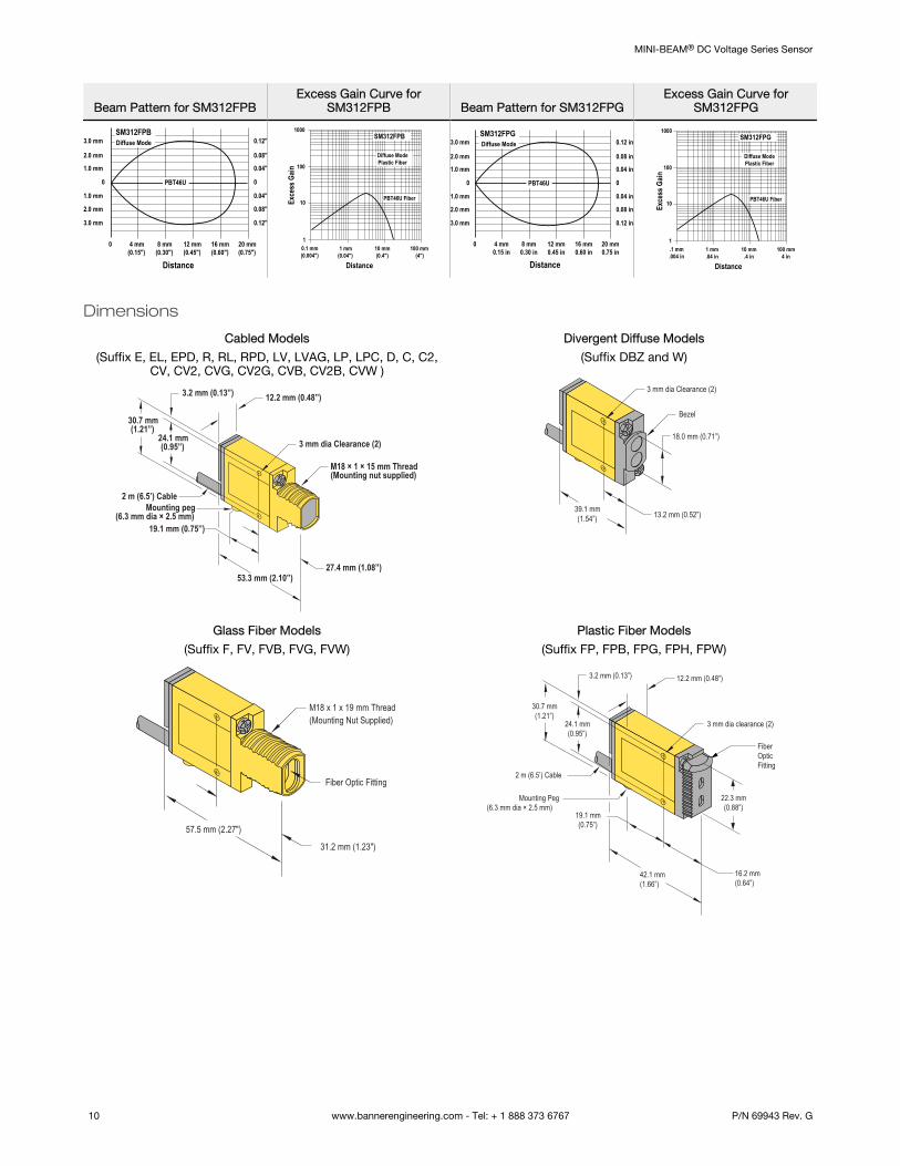
Beam Pattern for SM312FPBExcess Gain Curve for
SM312FPB Beam Pattern for SM312FPGExcess Gain Curve for
SM312FPG
20 mm(0.75")
16 mm(0.60")
12 mm(0.45")
8 mm(0.30")
4 mm(0.15")
0
0
1.0 mm
2.0 mm
3.0 mm
1.0 mm
2.0 mm
3.0 mm
0
0.04"
0.08"
0.12"
0.04"
0.08"
0.12"
Distance
SM312FPBDiffuse Mode
PBT46U
1
10
100
1 mm(0.04")
10 mm(0.4")
100 mm(4")
0.1 mm(0.004")
1000
Distance
SM312FPB
Diffuse ModePlastic Fiber
PBT46U FiberExce
ss G
ain
20 mm0.75 in
16 mm0.60 in
12 mm0.45 in
8 mm0.30 in
4 mm0.15 in
0
0
1.0 mm
2.0 mm
3.0 mm
1.0 mm
2.0 mm
3.0 mm
0
0.04 in
0.08 in
0.12 in
0.04 in
0.08 in
0.12 in
Distance
SM312FPGDiffuse Mode
PBT46U
1
10
100
1 mm.04 in
10 mm.4 in
100 mm4 in
.1 mm.004 in
1000
Distance
Exce
ss G
ain
SM312FPG
Diffuse ModePlastic Fiber
PBT46U Fiber
Dimensions
Cabled Models
(Suffix E, EL, EPD, R, RL, RPD, LV, LVAG, LP, LPC, D, C, C2,CV, CV2, CVG, CV2G, CVB, CV2B, CVW )
3.2 mm (0.13”) 12.2 mm (0.48”)
3 mm dia Clearance (2)
M18 × 1 × 15 mm Thread(Mounting nut supplied)
27.4 mm (1.08”)53.3 mm (2.10”)
19.1 mm (0.75”)
Mounting peg(6.3 mm dia × 2.5 mm)
2 m (6.5’) Cable
30.7 mm(1.21”)
24.1 mm(0.95”)
Divergent Diffuse Models
(Suffix DBZ and W)
3 mm dia Clearance (2)
Bezel
18.0 mm (0.71”)
13.2 mm (0.52”)39.1 mm(1.54”)
Glass Fiber Models
(Suffix F, FV, FVB, FVG, FVW)
M18 x 1 x 19 mm Thread(Mounting Nut Supplied)
57.5 mm (2.27")
31.2 mm (1.23")
Fiber Optic Fitting
Plastic Fiber Models
(Suffix FP, FPB, FPG, FPH, FPW)
3.2 mm (0.13”) 12.2 mm (0.48”)
3 mm dia clearance (2)
FiberOpticFitting
22.3 mm(0.88”)
16.2 mm(0.64”)
42.1 mm(1.66”)
19.1 mm(0.75”)
Mounting Peg(6.3 mm dia × 2.5 mm)
2 m (6.5’) Cable
30.7 mm(1.21”)
24.1 mm(0.95”)
MINI-BEAM® DC Voltage Series Sensor
10 www.bannerengineering.com - Tel: + 1 888 373 6767 P/N 69943 Rev. G

QD Models
20.0 mm(0.79”)
12 mm ThreadQuick-disconnect
Accessories
4-Pin Euro-Style Cordsets
4-Pin Threaded M12/Euro-Style Cordsets—Single Ended
Model Length Style Dimensions Pinout (Female)
MQDC-406 2 m (6.56 ft)
Straight
44 Typ.
ø 14.5M12 x 1
2
34
1
1 = Brown2 = White3 = Blue4 = Black
MQDC-415 5 m (16.4 ft)
MQDC-430 9 m (29.5 ft)
MQDC-450 15 m (49.2 ft)
MQDC-406RA 2 m (6.56 ft)
Right-Angle
32 Typ.[1.26"]
30 Typ.[1.18"]
ø 14.5 [0.57"]M12 x 1
MQDC-415RA 5 m (16.4 ft)
MQDC-430RA 9 m (29.5 ft)
MQDC-450RA 15 m (49.2 ft)
Mounting Brackets
SMB46L• Right-angle• L bracket• 14-ga. 316 stainless steel
Hole center spacing: A = 16.0
Hole size: A = 16.5 × 18.7
65
54
27 A
SMB46S• Right-angle• S bracket• 14-ga. 316 stainless steel
Hole center spacing: A = 16.0
Hole size: A = 16.5 × 18.7, B = 34.0 ×10.0
54
27 65 16
A B
SMB46U• Right-angle• U bracket for sensor
protection• 14-ga. 316 stainless steel
Hole center spacing: A = 16.0
Hole size: A = 16.5 × 18.7, B = 34.0 ×13.0
70
54
65A
B
SMB18A• Right-angle mounting
bracket with a curved slotfor versatile orientation
• 12-ga. stainless steel• 18 mm sensor mounting
hole• Clearance for M4 (#8)
hardware
30
41
46
A BC
Hole center spacing: A to B = 24.2Hole size: A = ø 4.6, B = 17.0 × 4.6, C = ø 18.5
MINI-BEAM® DC Voltage Series Sensor
P/N 69943 Rev. G www.bannerengineering.com - Tel: + 1 888 373 6767 11

SMB18AFA..• Protective, swivel bracket
with tilt and pan movementfor precision adjustment
• Easy sensor mounting toextruded rail T-slots
• Metric and inch size boltsavailable
• Mounting hole for 18 mmsensors
51
51
44
3/8-16 UNC
X 2 in.ø19.8
ø18.1
Hole size: B = ø 18.1
Model Bolt Thread (A)
SMB18AFA 3/8 - 16 × 2 in
SMB18AFAM10 M10 - 1.5 × 50
SMB18Q• Right-angle flanged bracket• 18 mm sensor mounting
hole• 12-ga. stainless steel
41
46A
B
30C
Hole center spacing: A to B = 24.2Hole size: A = ø 4.6, B = 17.0 × 4.6, C = ø 19.0
SMB18SF• 18 mm swivel bracket with
M18 × 1 internal thread• Black thermoplastic polyester• Stainless steel swivel locking
hardware included
B
A
51
42
25
Hole center spacing: A = 36.0Hole size: A = ø 5.3, B = ø 18.0
SMB18UR• 2-piece universal swivel
bracket• 300 series stainless steel• Stainless steel swivel
locking hardware included• Mounting hole for 18 mm
sensor
137
64 42
B
A
C
Hole center spacing: A = 25.4, B = 46.7Hole size: B = 6.9 × 32.0, C = ø 18.3
SMB312PD• Right-angle mounting
bracket with a curved slotfor versatile orientation
• 12-ga. stainless steel• 18 mm sensor mounting
hole• Clearance for M4 (#8)
hardware
46
41B
C
A
32
Hole center spacing: A to B = 24.2Hole size: A = ø 4.6, B = 17 × 4.6, C = ø 18.5
Note: Not for use with plastic fiber optic sensors
SMBAMS18RA• Right-angle SMBAMS
series bracket with 18 mmhole
• Articulation slots for 90+°rotation
• 12-ga. (2.6 mm) cold-rolledsteel
48
45
40
AB
C
Hole center spacing: A = 26.0, A to B = 13.0Hole size: A = 26.8 × 7.0, B = ø 6.5, C = ø 19.0
SMBAMS18P• Flat SMBAMS series
bracket with 18 mm hole• Articulation slots for 90+°
rotation• 12-ga. (2.6 mm) cold-rolled
steel
45
78
A
B
C
Hole center spacing: A = 26.0, A to B = 13.0Hole size: A = 26.8 × 7.0, B = ø 6.5, C = ø 19.0
SMB30SK• Flat-mount swivel bracket with
extended range of motion• Black reinforced thermoplastic
polyester and 316 stainless steel• Stainless steel swivel locking
hardware included
68
57
78
A
B
Hole center spacing: A = 50.8Hole size: A = ø 7, B = ø 18
MINI-BEAM® DC Voltage Series Sensor
12 www.bannerengineering.com - Tel: + 1 888 373 6767 P/N 69943 Rev. G

SMB3018SC• 18 mm swivel side or barrel-
mount bracket• Black reinforced
thermoplastic polyester• Stainless steel swivel
locking hardware included
B
A
67
59
29
Hole center spacing: A = 50.8Hole size: A = ø 7.0, B = ø 18.0
SMB30SUS• Side-mount swivel with
extended range of motion• Black reinforced thermoplastic
polyester• Stainless steel swivel locking
hardware included
A
67
58
29
B
Hole center spacing: A = 50.8, B = 24.1Hole size: A = ø 7, B = ø 7.6
SMB312S
• Stainless steel 2-axis, side-mount bracket
46
B
C
A
3220
A = 4.3 × 7.5, B = diam. 3, C = 3 × 15.3
SMB312B
• Stainless steel 2-axis,bottom-mount bracket
• Includes mounting foot
5124
23
B CA
A = diam. 6.9, B = 4.3 × 10.5, C = 3.1 × 15.2
Miscellaneous Accessories and Replacement PartsMINI-BEAM lens assemblies are field-replaceable.
Replacement Lens Model Replacement Lens for MINI-BEAM Model Possible Sensing Mode or Range Changes
UC-300AG LVAG LV to LVAG
UC-300BZ W and DBZ D to DBZ and F to DBZ
UC-300C..7 C, CV, and CVG CV2 to CV
UC-300C2 C2 and CV2 CV to CV2
UC-300E E and R -
UC-300EL EL and RL Extends the range of the E/R models
UC-300EPD EPD -
UC-300F F and FV D to F and DBZ to F
UC-300FP FP (old style) -
UC-300FP2 FP -
UC-300L LV and D F to D, LVAG to LV, and DBZ to D
UC-300LP LP -
UC-300RPD RPD -
MINI-BEAM right-angle reflectors are useful for tight sensing locations. These reflectors significantly decrease excess gain.
Right-Angle Reflectors
RAR300SM• Side mount right-angle reflector• Profile dimension of 14 mm (0.56
inches) in the direction of the scan• Use with MINI-BEAM models 31E,
EL, R, RL; and 312D, DBZ, LV, W
30.48 mm[1.2”]
42.4 mm[1.67”]
55.7 mm[2.2”]
12.7 mm[0.5”]
24.13 mm[0.95”] 3.18 mm dia
[0.125”]
45°
RAR300FM• Front mount right-angle reflector
that attaches directly to thethreaded barrel of most MINI-BEAMs
• Profile dimension of 34 mm (1.35inches) in the direction of the scan
• Use with MINI-BEAM models 31E,EL, R, RL; and 312D, LV
30.5 mm[1.2”]
24.13 mm[0.95”]
4.45 mm[0.18”]
32.5 mm[1.28”]
17.5 mm[0.69”]
dia 3.18mm (2)[0.125’”]
45°
37.6 mm[1.48”]
MINI-BEAM® DC Voltage Series Sensor
P/N 69943 Rev. G www.bannerengineering.com - Tel: + 1 888 373 6767 13

Opposed-mode MINI-BEAM sensors may be fitted with apertures that narrow or shape the effective beam of the sensor to moreclosely match the size or profile of the object to be sensed, for example, the use of “line” (or “slit”) apertures for sensing wire orthread. Each model contains 20 apertures.
MINI-BEAM Opposed-Mode Aperture Kits
Model Description Qty
Circular
AP31-020 0.5 mm dia. 20
AP31-040 1.0 mm dia. 20
AP31-100 2.5 mm dia. 20
Horizontal Slot
AP31-020H 0.5 x 6.4 mm 20
AP31-040H 1.0 x 6.4 mm 20
AP31-100H 2.5 x 6.4 mm 20
AP31-200H 5.1 x 6.4 mm 20
Vertical Slot
AP31-020V 0.5 x 12.7 mm 20
AP31-040V 1.0 x 12.7 mm 20
AP31-100V 2.5 x 12.7 mm 20
AP31-200V 5.1 x 12.7 mm 20
Kit
AP31-DVHX2 2 of each aperture 2
Aperture
Range (Standard Group I and II Sensor Pairs) Range (Group I Sensor Pairs with UC-300ELUpper Covers Substituted)Aperture on Both Emitter and Received Aperture on Receiver Only
Group I Sensors Group II Sensors Group I Sensors Group II SensorsAperture on Both
Emitter andReceived
Aperture on ReceiverOnly
AP31-020 89 mm 102 mm 457 mm 1.5 m 127 mm 914 mm
AP31-040 330 mm 457 mm 940 mm 3.2 m 183 mm 2 m
AP31-100 1.5 m 3 m 2.5 m 8.2 m 2.1 m 5.8 m
AP31-020H 406 mm 1.8 m 965 mm 9.1 m 864 mm 3.4 m
AP31-040H 914 mm 4 m 1.8 m 12.5 m 1.8 m 5.2 m
AP31-100H 2.3 m 10.4 m 2.9 m 20.7 m 5.2 m 8.5 m
AP31-200H 2.8 m 21.3 m 3 m 24.4 m 8.2 m 11 m
AP31-020V 457 mm 1.7 m 1 m 8.2 m 1 m 3.4 m
AP31-040V 1 m 5.5 m 1.8 m 15.8 m 2.1 m 5.5 m
AP31-100V 2.3 m 10.7 m 2.9 m 22.9 m 6.1 m 8.5 m
AP31-200V 2.8 m 22.9 m 3 m 25.9 m 8.5 m 11 m
GROUP I Emitter/ Receiver Pairs (see Range): SM31E/SM31R
GROUP II Emitter/ Receiver Pairs (see Range): SM31EL/SM31RL
Example: A MINI-BEAM sensor pair is in Group I. With an AP31-040 circular aperture on the receiver only, range is 940 mm (37 in).With AP31-040 apertures on both emitter and receiver, range is 330 mm (13 in). Group I range with AP31-040 apertures andUC-300EL upper covers on both units is 183 mm; range with receiver aperture only is 2 m (80 in).
MINI-BEAM® DC Voltage Series Sensor
14 www.bannerengineering.com - Tel: + 1 888 373 6767 P/N 69943 Rev. G

Banner Engineering Corp. Limited WarrantyBanner Engineering Corp. warrants its products to be free from defects in material and workmanship for one year following the date of shipment. Banner Engineering Corp. will repair orreplace, free of charge, any product of its manufacture which, at the time it is returned to the factory, is found to have been defective during the warranty period. This warranty does notcover damage or liability for misuse, abuse, or the improper application or installation of the Banner product.
THIS LIMITED WARRANTY IS EXCLUSIVE AND IN LIEU OF ALL OTHER WARRANTIES WHETHER EXPRESS OR IMPLIED (INCLUDING, WITHOUT LIMITATION, ANY WARRANTY OFMERCHANTABILITY OR FITNESS FOR A PARTICULAR PURPOSE), AND WHETHER ARISING UNDER COURSE OF PERFORMANCE, COURSE OF DEALING OR TRADE USAGE.
This Warranty is exclusive and limited to repair or, at the discretion of Banner Engineering Corp., replacement. IN NO EVENT SHALL BANNER ENGINEERING CORP. BE LIABLE TOBUYER OR ANY OTHER PERSON OR ENTITY FOR ANY EXTRA COSTS, EXPENSES, LOSSES, LOSS OF PROFITS, OR ANY INCIDENTAL, CONSEQUENTIAL OR SPECIAL DAMAGESRESULTING FROM ANY PRODUCT DEFECT OR FROM THE USE OR INABILITY TO USE THE PRODUCT, WHETHER ARISING IN CONTRACT OR WARRANTY, STATUTE, TORT,STRICT LIABILITY, NEGLIGENCE, OR OTHERWISE.
Banner Engineering Corp. reserves the right to change, modify or improve the design of the product without assuming any obligations or liabilities relating to any product previouslymanufactured by Banner Engineering Corp. Any misuse, abuse, or improper application or installation of this product or use of the product for personal protection applications when theproduct is identified as not intended for such purposes will void the product warranty. Any modifications to this product without prior express approval by Banner Engineering Corp willvoid the product warranties. All specifications published in this document are subject to change; Banner reserves the right to modify product specifications or update documentation atany time. Specifications and product information in English supersede that which is provided in any other language. For the most recent version of any documentation, refer to: www.bannerengineering.com.
For patent information, see www.bannerengineering.com/patents.
MINI-BEAM® DC Voltage Series Sensor
© Banner Engineering Corp. All rights reserved


![TAKEX PHOTOELECTRIC BEAM SENSOR lANTl-CRAWL] PB-lN](https://img.pdfslide.us/doc/110x75/58a2f00d1a28ab1f238bf6e0/takex-photoelectric-beam-sensor-lantl-crawl-pb-ln-.jpg)