Embed Size (px)
Citation preview
1
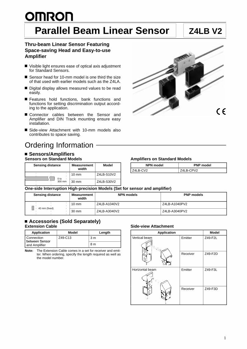
Parallel Beam Linear Sensor Z4LB V2Thru-beam Linear Sensor FeaturingSpace-saving Head and Easy-to-useAmplifier
Visible light ensures ease of optical axis adjustmentfor Standard Sensors.
Sensor head for 10-mm model is one third the sizeof that used with earlier models such as the Z4LA.
Digital display allows measured values to be readeasily.
Features hold functions, bank functions andfunctions for setting discrimination output accord-ing to the application.
Connector cables between the Sensor andAmplifier and DIN Track mounting ensure easyinstallation.
Side-view Attachment with 10-mm models alsocontributes to space saving.
Ordering Information Sensors/Amplifiers
Sensors on Standard ModelsSensing distance Measurement
widthModel
0 to
10 mm Z4LB-S10V20 to300 mm 30 mm Z4LB-S30V2
Amplifiers on Standard ModelsNPN model PNP model
Z4LB-CV2 Z4LB-CPV2
One-side Interruption High-precision Models (Set for sensor and amplifier)Sensing distance Measurement
widthNPN models PNP models
40 mm (fixed)
10 mm Z4LB-A1040V2 Z4LB-A1040PV240 mm (fixed)
30 mm Z4LB-A3040V2 Z4LB-A3040PV2
Accessories (Sold Separately)Extension Cable
Application Model Length
Connectionbetween Sensor
Z49-C13 3 mbetween Sensorand Amplifier 8 m
Note: The Extension Cable comes in a set for receiver and emit-ter. When ordering, specify the length required as well asthe model number.
Side-view AttachmentApplication Model
Vertical beam Emitter Z49-F2L
Receiver Z49-F2D
Horizontal beam Emitter Z49-F3L
Receiver Z49-F3D
Z4LB V2 Z4LB V2
2
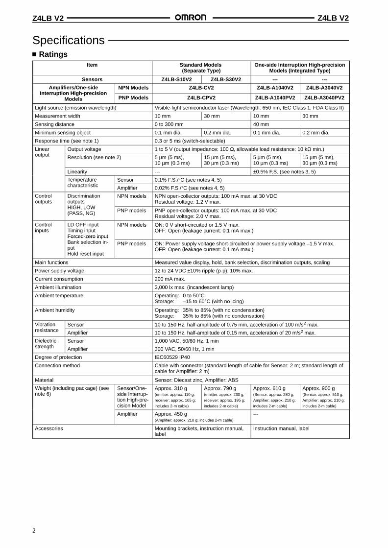
Specifications Ratings
Item Standard Models (Separate Type)
One-side Interruption High-precisionModels (Integrated T ype)
Sensors Z4LB-S10V2 Z4LB-S30V2 --- ---
Amplifiers/One-sideInterr ption High-precision
NPN Models Z4LB-CV2 Z4LB-A1040V2 Z4LB-A3040V2Interruption High-precision
Models PNP Models Z4LB-CPV2 Z4LB-A1040PV2 Z4LB-A3040PV2
Light source (emission wavelength) Visible-light semiconductor laser (Wavelength: 650 nm, IEC Class 1, FDA Class II)
Measurement width 10 mm 30 mm 10 mm 30 mm
Sensing distance 0 to 300 mm 40 mm
Minimum sensing object 0.1 mm dia. 0.2 mm dia. 0.1 mm dia. 0.2 mm dia.
Response time (see note 1) 0.3 or 5 ms (switch-selectable)
Lineart t
Output voltage 1 to 5 V (output impedance: 100 Ω, allowable load resistance: 10 kΩ min.)eaoutput Resolution (see note 2) 5 µm (5 ms),
10 µm (0.3 ms)15 µm (5 ms),30 µm (0.3 ms)
5 µm (5 ms),10 µm (0.3 ms)
15 µm (5 ms),30 µm (0.3 ms)
Linearity --- ±0.5% F.S. (see notes 3, 5)
Temperatureh t i ti
Sensor 0.1% F.S./°C (see notes 4, 5)e e a u echaracteristic Amplifier 0.02% F.S./°C (see notes 4, 5)
Controloutputs
DiscriminationoutputsHIGH LOW
NPN models NPN open-collector outputs: 100 mA max. at 30 VDCResidual voltage: 1.2 V max.
HIGH, LOW(PASS, NG) PNP models PNP open-collector outputs: 100 mA max. at 30 VDC
Residual voltage: 2.0 V max.
Controlinputs
LD OFF input Timing inputForced-zero input
NPN models ON: 0 V short-circuited or 1.5 V max.OFF: Open (leakage current: 0.1 mA max.)
Forced zero in utBank selection in-put Hold reset input
PNP models ON: Power supply voltage short-circuited or power supply voltage –1.5 V max.OFF: Open (leakage current: 0.1 mA max.)
Main functions Measured value display, hold, bank selection, discrimination outputs, scaling
Power supply voltage 12 to 24 VDC ±10% ripple (p-p): 10% max.
Current consumption 200 mA max.
Ambient illumination 3,000 lx max. (incandescent lamp)
Ambient temperature Operating: 0 to 50°CStorage: –15 to 60°C (with no icing)
Ambient humidity Operating: 35% to 85% (with no condensation)Storage: 35% to 85% (with no condensation)
Vibrationi t
Sensor 10 to 150 Hz, half-amplitude of 0.75 mm, acceleration of 100 m/s2 max.b a oresistance Amplifier 10 to 150 Hz, half-amplitude of 0.15 mm, acceleration of 20 m/s2 max.
Dielectrict th
Sensor 1,000 VAC, 50/60 Hz, 1 mine ec cstrength Amplifier 300 VAC, 50/60 Hz, 1 min
Degree of protection IEC60529 IP40
Connection method Cable with connector (standard length of cable for Sensor: 2 m; standard length ofcable for Amplifier: 2 m)
Material Sensor: Diecast zinc, Amplifier: ABS
Weight (including package) (seenote 6)
Sensor/One-side Interrup-tion High-pre-cision Model
Approx. 310 g(emitter: approx. 110 g;
receiver: approx. 105 g;
includes 2-m cable)
Approx. 790 g(emitter: approx. 230 g;
receiver: approx. 195 g;
includes 2-m cable)
Approx. 610 g(Sensor: approx. 280 g;
Amplifier: approx. 210 g;
includes 2-m cable)
Approx. 900 g(Sensor: approx. 510 g;
Amplifier: approx. 210 g;
includes 2-m cable)
Amplifier Approx. 450 g (Amplifier: approx. 210 g; includes 2-m cable)
---
Accessories Mounting brackets, instruction manual,label
Instruction manual, label
Z4LB V2 Z4LB V2
3
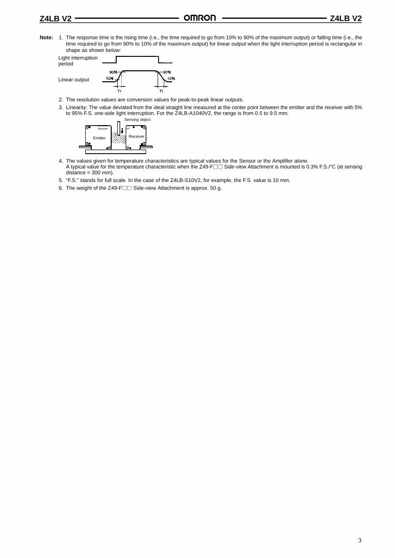
Note: 1. The response time is the rising time (i.e., the time required to go from 10% to 90% of the maximum output) or falling time (i.e., thetime required to go from 90% to 10% of the maximum output) for linear output when the light interruption period is rectangular inshape as shown below:
Light interruptionperiod
Linear output
2. The resolution values are conversion values for peak-to-peak linear outputs.
3. Linearity: The value deviated from the ideal straight line measured at the center point between the emitter and the receiver with 5%to 95% F.S. one-side light interruption. For the Z4LB-A1040V2, the range is from 0.5 to 9.5 mm.
Emitter Receiver
Sensing object
4. The values given for temperature characteristics are typical values for the Sensor or the Amplifier alone.A typical value for the temperature characteristic when the Z49-F Side-view Attachment is mounted is 0.3% F.S./°C (at sensingdistance = 300 mm).
5. “F.S.” stands for full scale. In the case of the Z4LB-S10V2, for example, the F.S. value is 10 mm.
6. The weight of the Z49-F Side-view Attachment is approx. 50 g.
Z4LB V2 Z4LB V2
4
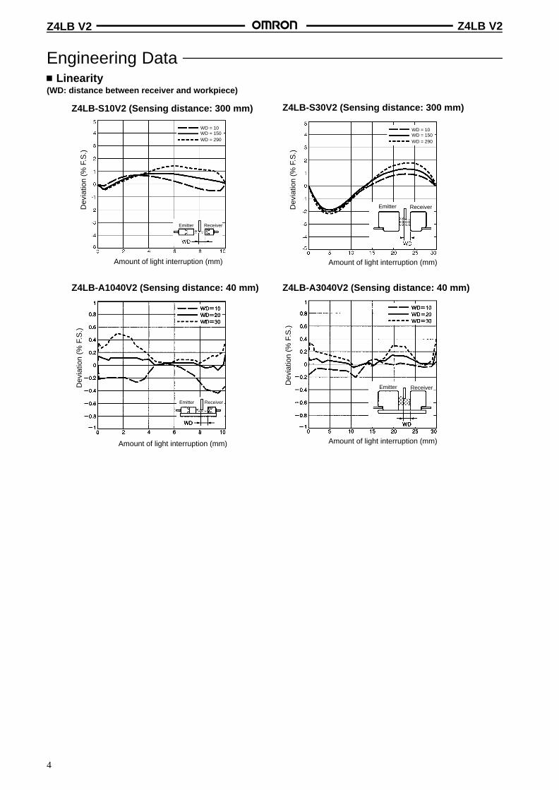
Engineering Data Linearity
(WD: distance between receiver and workpiece)
Z4LB-S10V2 (Sensing distance: 300 mm) Z4LB-S30V2 (Sensing distance: 300 mm)
Dev
iatio
n (%
F.S
.)
Amount of light interruption (mm)
Dev
iatio
n (%
F.S
.)
Amount of light interruption (mm)
Emitter Receiver
WD = 10WD = 150WD = 290
WD = 10WD = 150WD = 290
Z4LB-A3040V2 (Sensing distance: 40 mm)
Emitter
Dev
iatio
n (%
F.S
.)
Receiver
Emitter
Dev
iatio
n (%
F.S
.)
Receiver
Amount of light interruption (mm) Amount of light interruption (mm)
Z4LB-A1040V2 (Sensing distance: 40 mm)
Emitter Receiver
Z4LB V2 Z4LB V2
5
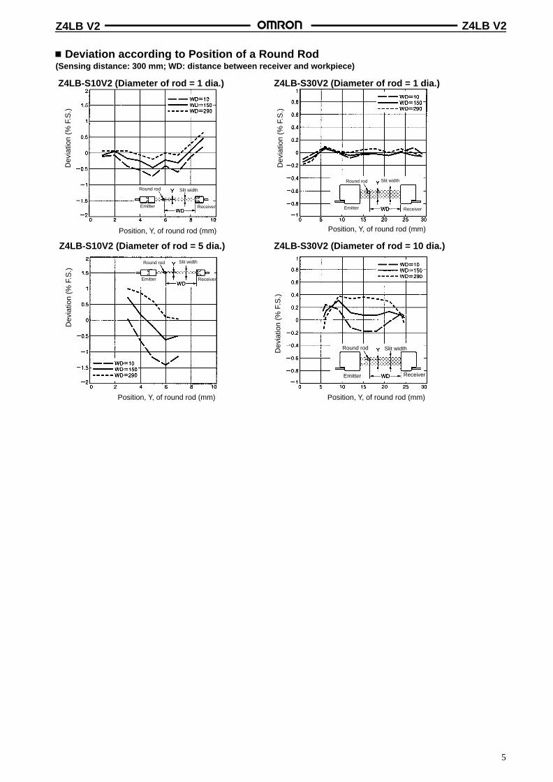
Deviation according to Position of a Round Rod(Sensing distance: 300 mm; WD: distance between receiver and workpiece)
Z4LB-S30V2 (Diameter of rod = 1 dia.)
Z4LB-S10V2 (Diameter of rod = 5 dia.) Z4LB-S30V2 (Diameter of rod = 10 dia.)
Dev
iatio
n (%
F.S
.)
Emitter Receiver
Round rod Slit width
Position, Y, of round rod (mm)
Emitter Receiver
Round rod Slit width
Position, Y, of round rod (mm)
Dev
iatio
n (%
F.S
.)Emitter Receiver
Round rod Slit width
Position, Y, of round rod (mm)
Dev
iatio
n (%
F.S
.)
Emitter Receiver
Round rod Slit width
Position, Y, of round rod (mm)
Dev
iatio
n (%
F.S
.)
Z4LB-S10V2 (Diameter of rod = 1 dia.)
Z4LB V2 Z4LB V2
6
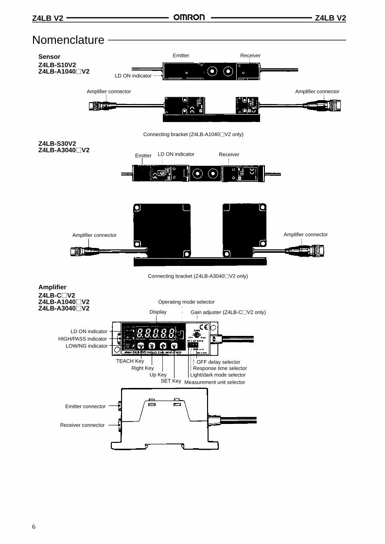
NomenclatureSensorZ4LB-S10V2Z4LB-A1040V2
Z4LB-S30V2Z4LB-A3040V2
AmplifierZ4LB-CV2Z4LB-A1040V2Z4LB-A3040V2
Emitter Receiver
LD ON indicator
Amplifier connector Amplifier connector
Connecting bracket (Z4LB-A1040V2 only)
Emitter ReceiverLD ON indicator
Amplifier connector Amplifier connector
Connecting bracket (Z4LB-A3040V2 only)
LOW/NG indicator
Display
TEACH KeyRight Key
Up KeySET Key
Operating mode selector
Gain adjuster (Z4LB-CV2 only)
Measurement unit selectorLight/dark mode selector
Response time selectorOFF delay selector
Emitter connector
Receiver connector
LD ON indicatorHIGH/PASS indicator
Z4LB V2 Z4LB V2
7
Operation Functions
Function Description
Displayfunctions
LD ON indicator Lights when laser beams are emitted.
The Sensor and Amplifier indicators light at the same time.
Display (with measurement unitselection and light/dark modeselection functions)
Displays either linear output voltage (V) or length (mm) according to themeasurement unit selector switch setting.
If the measurement unit is set to length (mm), set the measurement width to be used.The default setting is 10 mm.
The amount of incident light or light interruption can be selected using the light/darkmode selector switch.
HIGH/PASS indicator Lights when HIGH/PASS discrimination output turns ON.
LOW/NG indicator Lights when LOW/NG discrimination output turns ON.
Forced-zero indicator(displayed as the lowestdecimal place)
Lights when the forced-zero settings are enabled in RUN mode.
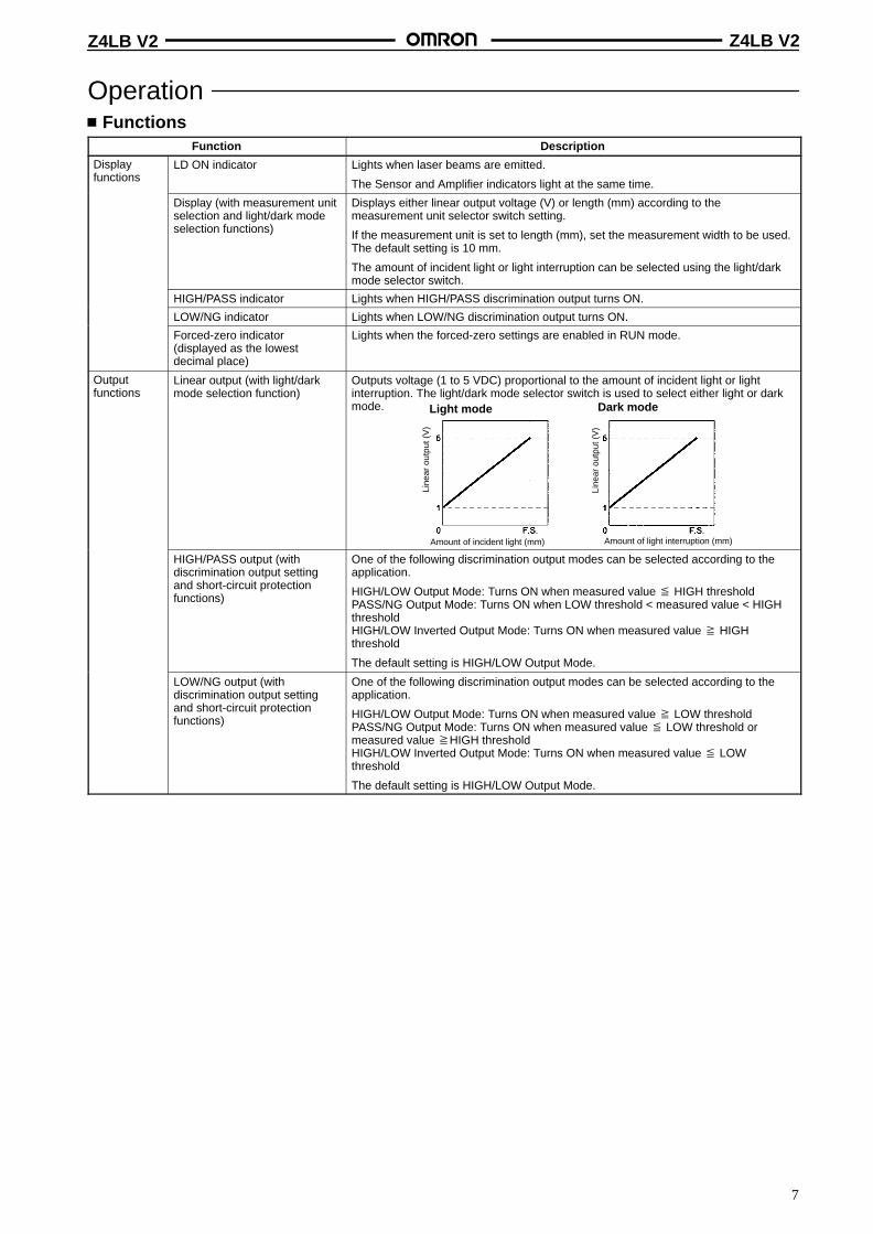
Outputfunctions
Linear output (with light/darkmode selection function)
Outputs voltage (1 to 5 VDC) proportional to the amount of incident light or lightinterruption. The light/dark mode selector switch is used to select either light or darkmode. Light mode
Amount of incident light (mm)
Dark mode
Amount of light interruption (mm)
Line
ar o
utpu
t (V
)
Line
ar o
utpu
t (V
)
HIGH/PASS output (withdiscrimination output settingand short-circuit protectionfunctions)
One of the following discrimination output modes can be selected according to theapplication.
HIGH/LOW Output Mode: Turns ON when measured value HIGH thresholdPASS/NG Output Mode: Turns ON when LOW threshold < measured value < HIGHthresholdHIGH/LOW Inverted Output Mode: Turns ON when measured value HIGHthreshold
The default setting is HIGH/LOW Output Mode.
LOW/NG output (withdiscrimination output settingand short-circuit protectionfunctions)
One of the following discrimination output modes can be selected according to theapplication.
HIGH/LOW Output Mode: Turns ON when measured value LOW thresholdPASS/NG Output Mode: Turns ON when measured value LOW threshold ormeasured value HIGH thresholdHIGH/LOW Inverted Output Mode: Turns ON when measured value LOWthreshold
The default setting is HIGH/LOW Output Mode.
Z4LB V2 Z4LB V2
8
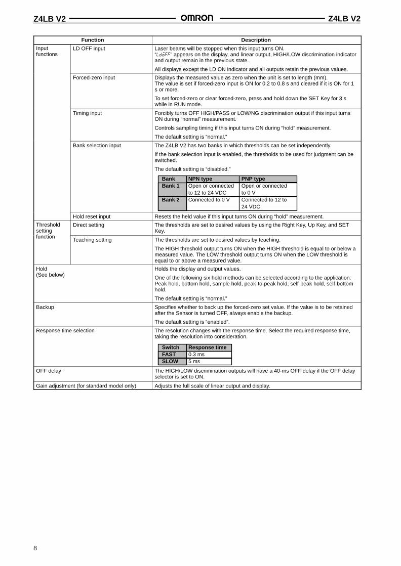
Function Description
Inputfunctions
LD OFF input Laser beams will be stopped when this input turns ON.“ldoff” appears on the display, and linear output, HIGH/LOW discrimination indicatorand output remain in the previous state.
All displays except the LD ON indicator and all outputs retain the previous values.
Forced-zero input Displays the measured value as zero when the unit is set to length (mm).The value is set if forced-zero input is ON for 0.2 to 0.8 s and cleared if it is ON for 1s or more.
To set forced-zero or clear forced-zero, press and hold down the SET Key for 3 swhile in RUN mode.
Timing input Forcibly turns OFF HIGH/PASS or LOW/NG discrimination output if this input turnsON during “normal” measurement.
Controls sampling timing if this input turns ON during “hold” measurement.
The default setting is “normal.”
Bank selection input The Z4LB V2 has two banks in which thresholds can be set independently.
If the bank selection input is enabled, the thresholds to be used for judgment can beswitched.
The default setting is “disabled.”
BankBank 1
Bank 2
NPN typeOpen or connectedto 12 to 24 VDCConnected to 0 V
PNP typeOpen or connectedto 0 VConnected to 12 to24 VDC
Hold reset input Resets the held value if this input turns ON during “hold” measurement.
Thresholdsettingf ti
Direct setting The thresholds are set to desired values by using the Right Key, Up Key, and SETKey.g
functionTeaching setting The thresholds are set to desired values by teaching.
The HIGH threshold output turns ON when the HIGH threshold is equal to or below ameasured value. The LOW threshold output turns ON when the LOW threshold isequal to or above a measured value.
Hold(See below)
Holds the display and output values.
One of the following six hold methods can be selected according to the application:Peak hold, bottom hold, sample hold, peak-to-peak hold, self-peak hold, self-bottomhold.
The default setting is “normal.”
Backup Specifies whether to back up the forced-zero set value. If the value is to be retainedafter the Sensor is turned OFF, always enable the backup.
The default setting is “enabled”.
Response time selection The resolution changes with the response time. Select the required response time,taking the resolution into consideration.
SwitchFASTSLOW
Response time0.3 ms5 ms
OFF delay The HIGH/LOW discrimination outputs will have a 40-ms OFF delay if the OFF delayselector is set to ON.
Gain adjustment (for standard model only) Adjusts the full scale of linear output and display.
Z4LB V2 Z4LB V2
9
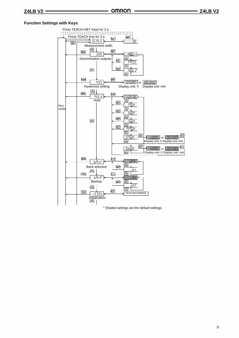
Function Settings with Keys
Press TEACH+SET Keys for 3 s.
Press TEACH Key for 3 s.
Measurement width
Discrimination outputs
Hysteresis setting Display unit: V Display unit: mm
Hold
Runmode
Bank selection
Backup
Initialization
All set value initialized
* Shaded settings are the default settings.
Display unit: V Display unit: mm
Display unit: V Display unit: mm
scale
out
hys
hold
banp
bank
reset
10
hl1
pass
hl2
0.020 00.050
norml
ph
bh
sh
pph
sph
sbh
off
on
on
1.000
1.000
00.000
00.000
off
Z4LB V2 Z4LB V2
10
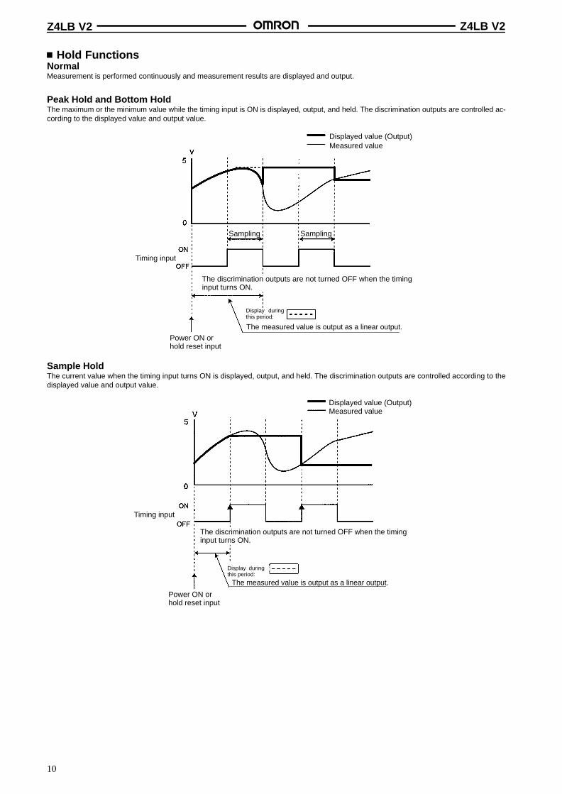
Hold FunctionsNormalMeasurement is performed continuously and measurement results are displayed and output.
Peak Hold and Bottom HoldThe maximum or the minimum value while the timing input is ON is displayed, output, and held. The discrimination outputs are controlled ac-cording to the displayed value and output value.
Displayed value (Output)Measured value
Sampling Sampling
Timing input
The discrimination outputs are not turned OFF when the timinginput turns ON.
Power ON orhold reset input
Display duringthis period:
The measured value is output as a linear output.
Sample HoldThe current value when the timing input turns ON is displayed, output, and held. The discrimination outputs are controlled according to thedisplayed value and output value.
Displayed value (Output)Measured value
Timing input
The discrimination outputs are not turned OFF when the timinginput turns ON.
Power ON orhold reset input
Display duringthis period:
The measured value is output as a linear output.
Z4LB V2 Z4LB V2
11
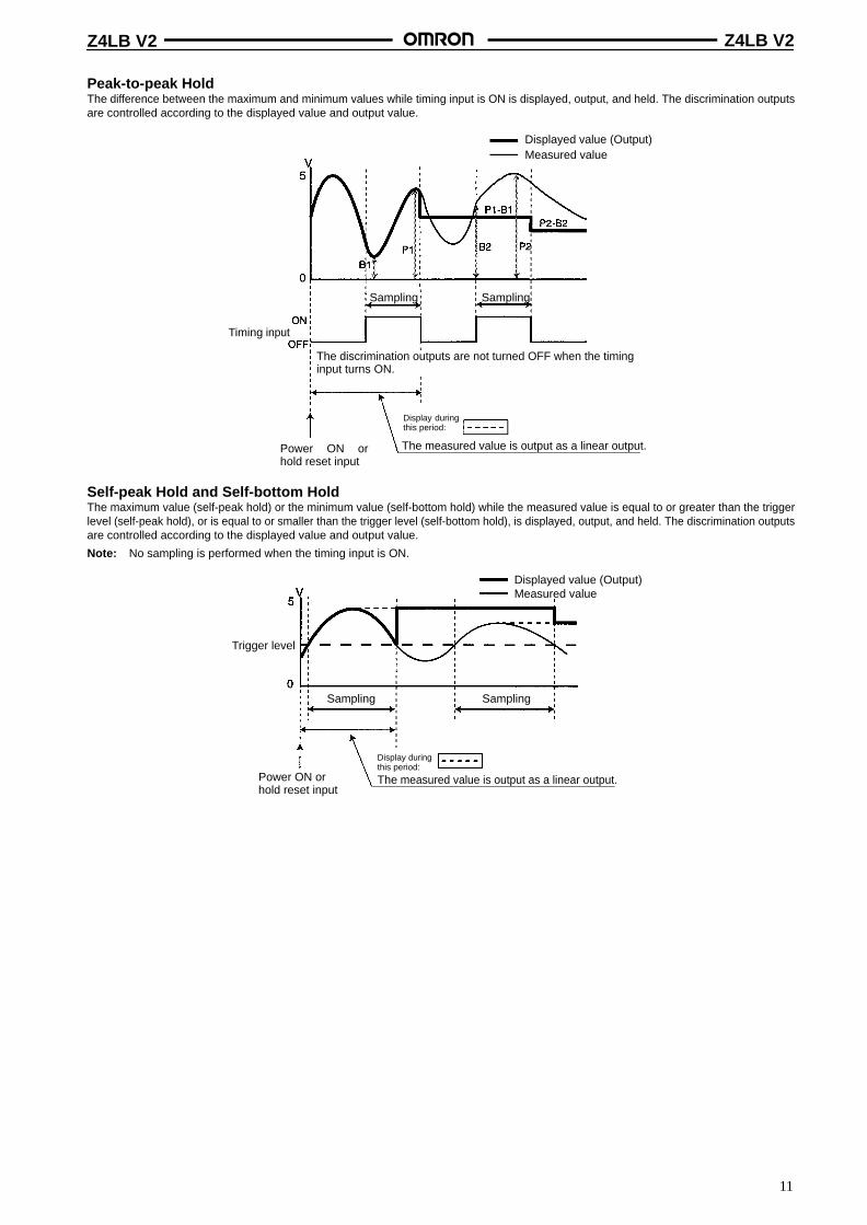
Peak-to-peak HoldThe difference between the maximum and minimum values while timing input is ON is displayed, output, and held. The discrimination outputsare controlled according to the displayed value and output value.
Displayed value (Output)Measured value
Sampling Sampling
Timing input
The discrimination outputs are not turned OFF when the timinginput turns ON.
Power ON orhold reset input
Display duringthis period:
The measured value is output as a linear output.
Self-peak Hold and Self-bottom HoldThe maximum value (self-peak hold) or the minimum value (self-bottom hold) while the measured value is equal to or greater than the triggerlevel (self-peak hold), or is equal to or smaller than the trigger level (self-bottom hold), is displayed, output, and held. The discrimination outputsare controlled according to the displayed value and output value.
Note: No sampling is performed when the timing input is ON.
Displayed value (Output)Measured value
Trigger level
Sampling Sampling
Power ON orhold reset input
Display duringthis period:
The measured value is output as a linear output.
Z4LB V2 Z4LB V2
12
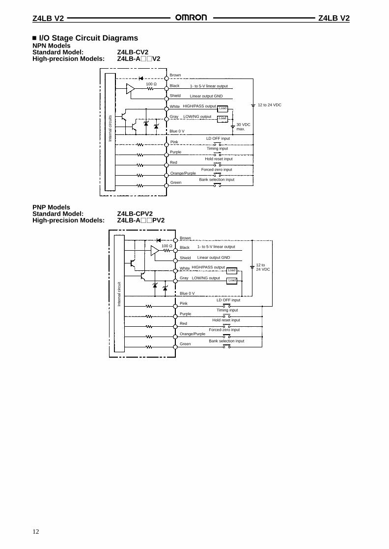
I/O Stage Circuit DiagramsNPN ModelsStandard Model: Z4LB-CV2High-precision Models: Z4LB-A V2
100 Ω
Load
Load
30 VDCmax.
12 to 24 VDC
Brown
Black
Shield
Gray
Blue 0 V
Pink
White
Purple
Red
Orange/Purple
Green
Inte
rnal
circ
uits
1- to 5-V linear output
Linear output GND
HIGH/PASS output
LOW/NG output
LD OFF input
Timing input
Hold reset input
Forced-zero input
Bank selection input
PNP ModelsStandard Model: Z4LB-CPV2High-precision Models: Z4LB-A PV2
12 to 24 VDC
100 Ω
Brown
Black
Shield
Gray
Blue 0 V
Pink
White
Purple
Red
Orange/Purple
Green
Inte
rnal
circ
uit
1- to 5-V linear output
Linear output GND
HIGH/PASS outputLoad
LoadLOW/NG output
LD OFF input
Timing input
Hold reset input
Forced-zero input
Bank selection input
Z4LB V2 Z4LB V2
13
DimensionsNote: All units are in millimeters unless otherwise indicated.
SensorZ4LB-S10V2
Two, M3 × 25Philips pan head screws
Vinyl insulated round cable, 4 dia.Standard length: 2 m
ConnectorTwo, M3Effective screw depth: 3
Two, Hexagonal nuts
Optical axis
Opticalaxis
Lens(13×7)
Slit(10×1)
Two, Hexagonal nuts
Two, M3 × 25Philips pan head screws
Vinyl insulated round cable, 4 dia.Standard length: 2 m
ConnectorTwo, M3Effective screwdepth: 3
Mounting Hole Cutout Dimensions
ReceiverEmitter
SensorZ4LB-A1040V2
Vinyl insulated round cable, 4 dia.Standard length: 2 m
Opticalaxis
Vinyl insulated round cable, 4 dia.Standard length: 2 m
Two, 4.4-dia. holes11 dia. spot facing depth: 5
Beam
Connector
Optical axisEmitter side Receiver sideConnector
Mounting Hole Cutout Dimensions
11.5 dia.
4 dia.4 dia.
Two, M3 Two, M3
11.5 dia.
Two, M4
14.7 dia.
14.7 dia.
Z4LB V2 Z4LB V2
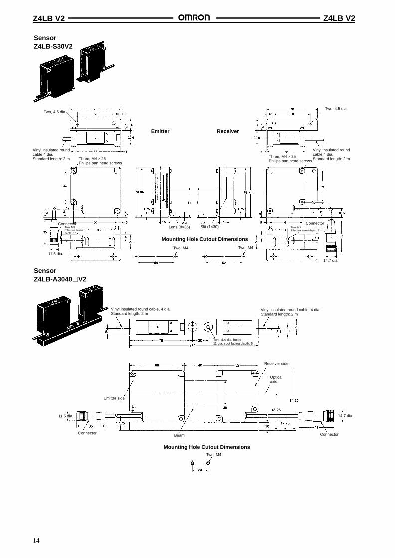
14
SensorZ4LB-S30V2
Mounting Hole Cutout Dimensions
ReceiverEmitter
SensorZ4LB-A3040V2
Vinyl insulated round cable, 4 dia.Standard length: 2 m
Vinyl insulated round cable, 4 dia.Standard length: 2 m
Two, 4.4-dia. holes11 dia. spot facing depth: 5
BeamConnector
Opticalaxis
Emitter side
Receiver side
Connector
Mounting Hole Cutout Dimensions
Vinyl insulated roundcable 4 dia.Standard length: 2 m Three, M4 × 25
Philips pan head screws
ConnectorTwo, M3Effective screwdepth: 5
Lens (8×36) Slit (1×30)
Vinyl insulated roundcable 4 dia.Standard length: 2 mThree, M4 × 25
Philips pan head screws
Two, M3Effective screw depth: 5
Connector
Two, 4.5 dia.
11.5 dia.
Two, M4 Two, M4
14.7 dia.
11.5 dia. 14.7 dia.
Two, M4
Two, 4.5 dia.
Z4LB V2 Z4LB V2
15
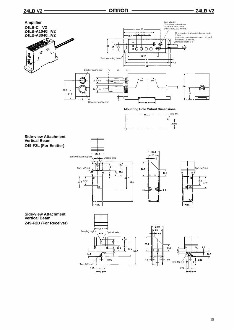
AmplifierZ4LB-CV2Z4LB-A1040V2Z4LB-A3040V2
Mounting Hole Cutout Dimensions
Side-view AttachmentVertical BeamZ49-F2L (For Emitter)
Optical axisEmitted beam region
Gain adjuster(There is no gain adjusteron Z4LB-A1040V2 orZ4LB-A3040V2 models.)
10-conductor, vinyl insulated round cable,5.8 dia.(conductor cross-sectional area: 1.63 mm2,insulation: 1.1 mm dia.)Standard length: 2 m
Two mounting holes
Emitter connector
Receiver connector
Side-view AttachmentVertical BeamZ49-F2D (For Receiver)
Optical axisSensing region
11.5 dia.
14.7 dia.
Two, M4
Two, M2 × 4 Two, M2 × 4
Two, M2 × 4Two, M2 × 4
Z4LB V2 Z4LB V2
16
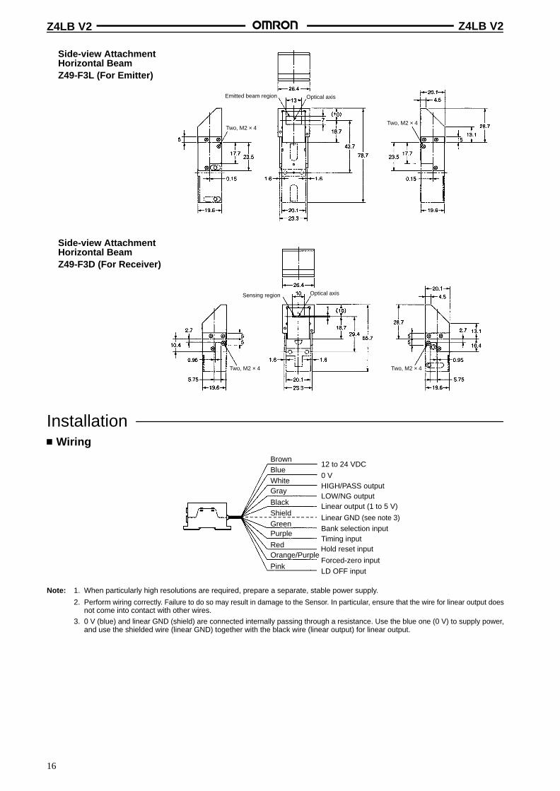
Side-view AttachmentHorizontal BeamZ49-F3L (For Emitter)
Optical axisEmitted beam region
Side-view AttachmentHorizontal BeamZ49-F3D (For Receiver)
Optical axisSensing region
Two, M2 × 4Two, M2 × 4
Two, M2 × 4 Two, M2 × 4
Installation Wiring
BrownBlueWhiteGray
BlackShield
12 to 24 VDC
0 VHIGH/PASS outputLOW/NG outputLinear output (1 to 5 V)
Linear GND (see note 3)GreenPurple
RedOrange/Purple
Pink
Bank selection inputTiming input
Hold reset input
Forced-zero inputLD OFF input
Note: 1. When particularly high resolutions are required, prepare a separate, stable power supply.
2. Perform wiring correctly. Failure to do so may result in damage to the Sensor. In particular, ensure that the wire for linear output doesnot come into contact with other wires.
3. 0 V (blue) and linear GND (shield) are connected internally passing through a resistance. Use the blue one (0 V) to supply power,and use the shielded wire (linear GND) together with the black wire (linear output) for linear output.
Z4LB V2 Z4LB V2
17
Precautions Designing the Setup
CompatibilityThere is general compatibility between Sensors and Amplifiers forstandard models. However, the emitters and the receivers areinspected as sets before delivery. Operation is possible using theemitters or the receivers from other sets, but in order to satisfy spec-ifications, the serial number of the emitter and the receiver must bethe same.
With high-precision models, the Sensor and the Amplifier areadjusted as a set. Only use combinations with the same serial num-ber.
Mutual InterferenceOperation is possible with two or more Sensors mounted together,but operation is not possible with two or more beams in close prox-imity. If the Sensor is used in this way, it may cause malfunction.
Wiring PrecautionsWiring and Power SupplyDo not impose voltage exceeding the rated voltage, otherwise theSensor may be damaged.
When supplying power to the Sensor, make sure that the polarity ofthe power is correct, otherwise, the Sensor may be damaged.
Do not short-circuit the load supplied with open collector output,otherwise the Sensor may be damaged.
Do not lay a power supply cable for the Z4LB V2 together with high-voltage lines or power lines to prevent interference, damage, andmalfunction.
The Z49-C13 Extension cable (3 or 8 m in length) can be connectedto the Sensor cable or Amplifier cable. The total length of the Sensorcable or Amplifier cable, however, must be 10 m or less. Use ashielded cable to extend the Amplifier cable, in which case, ashielded cable that is the same as that of the Amplifier cable must beused.
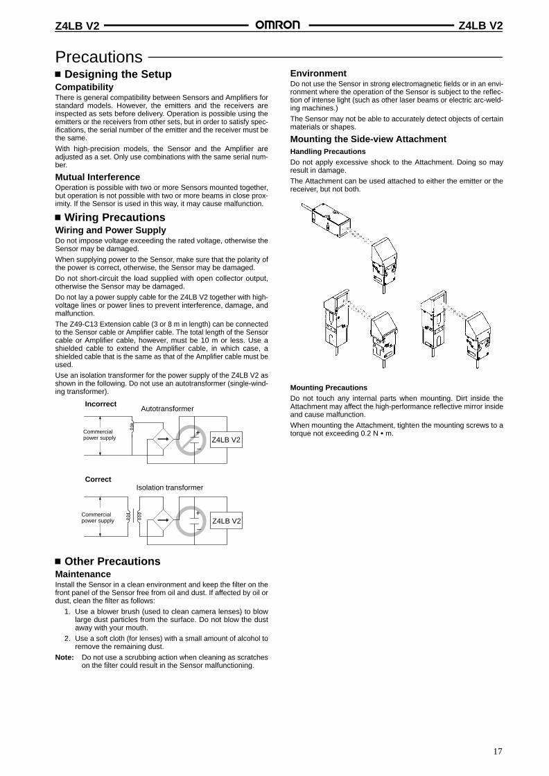
Use an isolation transformer for the power supply of the Z4LB V2 asshown in the following. Do not use an autotransformer (single-wind-ing transformer).
Incorrect
Commercialpower supply
Isolation transformer
Commercialpower supply
Autotransformer
Z4LB V2
Z4LB V2
+
–
+
–
Correct
Other PrecautionsMaintenanceInstall the Sensor in a clean environment and keep the filter on thefront panel of the Sensor free from oil and dust. If affected by oil ordust, clean the filter as follows:
1. Use a blower brush (used to clean camera lenses) to blowlarge dust particles from the surface. Do not blow the dustaway with your mouth.
2. Use a soft cloth (for lenses) with a small amount of alcohol toremove the remaining dust.
Note: Do not use a scrubbing action when cleaning as scratcheson the filter could result in the Sensor malfunctioning.
EnvironmentDo not use the Sensor in strong electromagnetic fields or in an envi-ronment where the operation of the Sensor is subject to the reflec-tion of intense light (such as other laser beams or electric arc-weld-ing machines.)
The Sensor may not be able to accurately detect objects of certainmaterials or shapes.
Mounting the Side-view AttachmentHandling PrecautionsDo not apply excessive shock to the Attachment. Doing so mayresult in damage.
The Attachment can be used attached to either the emitter or thereceiver, but not both.
Mounting PrecautionsDo not touch any internal parts when mounting. Dirt inside theAttachment may affect the high-performance reflective mirror insideand cause malfunction.
When mounting the Attachment, tighten the mounting screws to atorque not exceeding 0.2 N m.
Z4LB V2 Z4LB V2
18
Laser SafetyThe Z4LB V2 Parallel Beam Linear Sensor, is a Class 1 Laser Product according to EN60825-1 (IEC825-1) and a Class II Laser Productaccording to FDA (21 CFR1040.10) (see note). The Z4LB V2 is meant to be built into final system equipment. Pay special attention to thefollowing precautions for the safe use of the product:
Note: Europe: Class 1 of EN60825-1: 1994 = IEC825-1: 1993U.S.A.: Class II of FDA (21 CFR1040.10)
1. Use this product as specified in this datasheet. Otherwise, you may be exposed to hazardous laser radiation.
2. Be careful not to expose your eyes directly to the laser radiation or indirectly to laser radiation reflected from mirror or shiny surfaces.
3. To avoid exposure to hazardous laser radiation, do not displace nor remove the protective housing during operation, maintenance, andany other servicing.
4. The user should return the product to OMRON for all repair and servicing.
5. As for other countries, observe the regulations and standards specified by each country.
Requirements from Regulations and StandardsEN60825-1 “Safety of Laser Products, Equipment Classification, Requirements and User’s Guide”Summary of Manufacturer ’s Requirements
Requirements;S b l
Classificationequ e e sSub-clause Class 1 Class 2 Class 3A Class 3B* Class 4
Description of haz-ard class
Safe under reason-ably foreseeableconditions
Low power; eyeprotection normallyafforded by aversionresponses
Same as Class 2.Direct intrabeamviewing with opticalaids may be hazard-ous
Direct intrabeamviewing may be haz-ardous
High power; diffusedreflection may behazardous
Protective housing Required for each laser product; limits access necessary for performance of functions of the products
Safety interlock inprotective housing
Designed to prevent removal of the panel until accessible emission values are below the AEL for the class as-signed
Remote control Not required Permits easy addition of external interlockin laser installation
Key control Not required Laser inoperative when key is removed
Emission warningdevice
Not required Gives audible or visible warning when laseris switched on or if capacitor bank ofpulsed laser is being charged
Attenuator Not required Gives means beside ON/OFF switch totemporarily block beam
Location controls Not required Controls so located that there is no danger of exposure to AEL(see note 2) above Classes 1 or 2 when adjustments are made.
Viewing optics Emission from all viewing systems must be below Class 1 AEL’s as applicable
Scanning Scan failure shall not cause product to exceed its classification
Class label Required wording Figures A and B and specified wording
Aperture label Not required Specified wording required
Service entry label Required as appropriate to the class of accessible radiation
Override interlock la-bel
Required under certain conditions as appropriate to the class of laser used
User information Operation manuals must contain instructions for safe use
Purchasing and ser-vice information
Promotion brochures must reproduce classification labels; service manuals must contain safety information
Medical products Special calibration instructions required Special calibration instructions, means formeasurement and target-indicator required
Fibre optic Cable service connections require tool to disconnect if disconnection breaks protective housing and permitsaccess above Class 1
* With respect to the requirements of remote interlock connector, key control, emission warning and attenuator, Class 3B laser products notexceeding five times the AEL of Class 2 in the wavelength range of 400 nm to 700 nm are to be treated as Class 3A laser products.
Note: 1. This table is intended to provide a convenient summary of requirements. See text of this standard for complete requirements.
2. AEL: Accessible Emission LimitThe maximum accessible emission level permitted within a particular class.For your reference, see ANSI Z136.1-1993, Section 2.
Z4LB V2 Z4LB V2
19
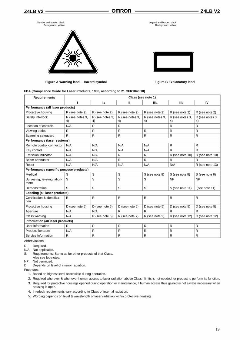
Symbol and border: blackBackground: yellow
Figure A W arning label – Hazard symbol
Legend and border: blackBackground: yellow
Figure B Explanatory label
FDA (Compliance Guide for Laser Products, 1985, according to 21 CFR1040.10)
Requirements Class (see note 1)equ e e s
I IIa II IIIa IIIb IVPerformance (all laser products)
Protective housing R (see note 2) R (see note 2) R (see note 2) R (see note 2) R (see note 2) R (see note 2)
Safety interlock R (see notes 3,4)
R (see notes 3,4)
R (see notes 3,4)
R (see notes 3,4)
R (see notes 3,4)
R (see notes 3,4)
Location of controls N/A R R R R
Viewing optics R R R R R R
Scanning safeguard R R R R R R
Performance (laser systems)
Remote control connector N/A N/A N/A N/A R R
Key control N/A N/A N/A N/A R R
Emission indicator N/A N/A R R R (see note 10) R (see note 10)
Beam attenuator N/A N/A R R R R
Reset N/A N/A N/A N/A N/A R (see note 13)
Performance (specific purpose products)
Medical S S S S (see note 8) S (see note 8) S (see note 8)
Surveying, leveling, align-ment
S S S S NP NP
Demonstration S S S S S (see note 11) (see note 11)
Labeling (all laser products)
Certification & identifica-tion
R R R R R R
Protective housing D (see note 5) D (see note 5) D (see note 5) D (see note 5) D (see note 5) D (see note 5)
Aperture N/A N/A R R R R
Class warning N/A R (see note 6) R (see note 7) R (see note 9) R (see note 12) R (see note 12)
Information (all laser products)
User information R R R R R R
Product literature N/A R R R R R
Service information R R R R R R
Abbreviations:
R: Required.N/A: Not applicable.S: Requirements: Same as for other products of that Class.
Also see footnotes.NP: Not permitted.D: Depends on level of interior radiation.Footnotes:
1. Based on highest level accessible during operation.
2. Required wherever & whenever human access to laser radiation above Class I limits is not needed for product to perform its function.
3. Required for protective housings opened during operation or maintenance, if human access thus gained is not always necessary whenhousing is open.
4. Interlock requirements vary according to Class of internal radiation.
5. Wording depends on level & wavelength of laser radiation within protective housing.
Z4LB V2 Z4LB V2
20
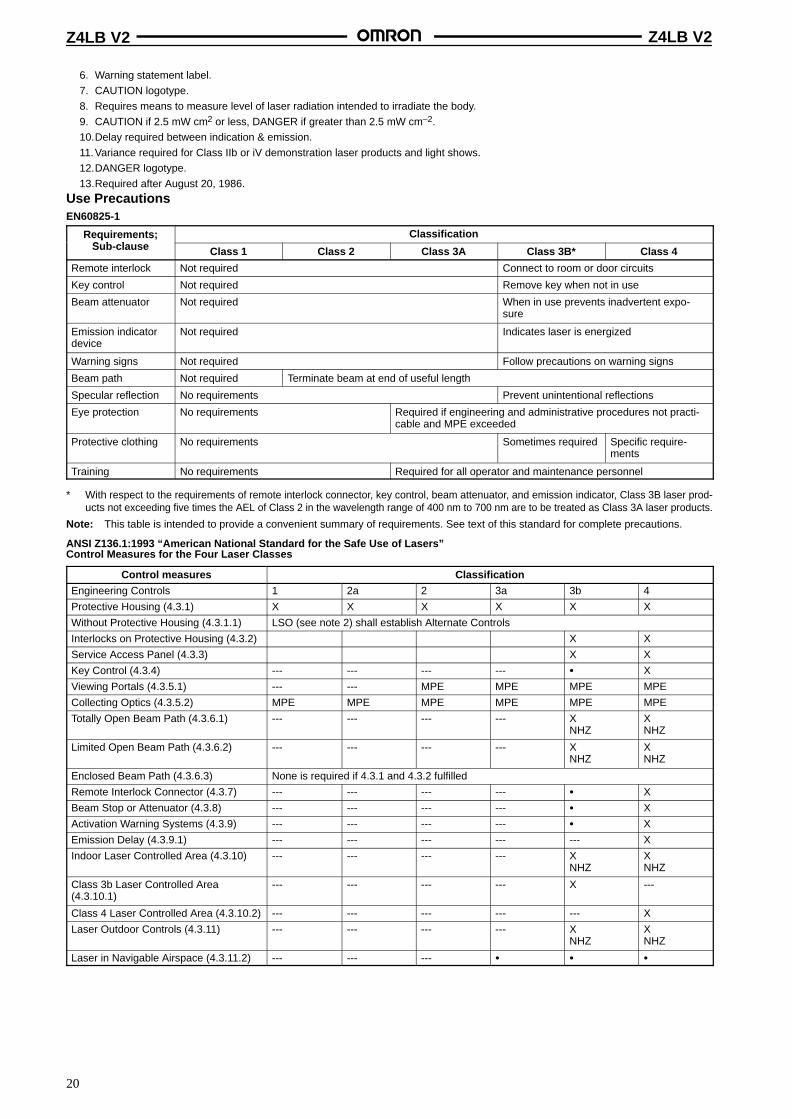
6. Warning statement label.
7. CAUTION logotype.
8. Requires means to measure level of laser radiation intended to irradiate the body.
9. CAUTION if 2.5 mW cm2 or less, DANGER if greater than 2.5 mW cm–2.
10.Delay required between indication & emission.
11.Variance required for Class IIb or iV demonstration laser products and light shows.
12.DANGER logotype.
13.Required after August 20, 1986.
Use PrecautionsEN60825-1
Requirements;S b l
Classificationequ e e sSub-clause Class 1 Class 2 Class 3A Class 3B* Class 4
Remote interlock Not required Connect to room or door circuits
Key control Not required Remove key when not in use
Beam attenuator Not required When in use prevents inadvertent expo-sure
Emission indicatordevice
Not required Indicates laser is energized
Warning signs Not required Follow precautions on warning signs
Beam path Not required Terminate beam at end of useful length
Specular reflection No requirements Prevent unintentional reflections
Eye protection No requirements Required if engineering and administrative procedures not practi-cable and MPE exceeded
Protective clothing No requirements Sometimes required Specific require-ments
Training No requirements Required for all operator and maintenance personnel
* With respect to the requirements of remote interlock connector, key control, beam attenuator, and emission indicator, Class 3B laser prod-ucts not exceeding five times the AEL of Class 2 in the wavelength range of 400 nm to 700 nm are to be treated as Class 3A laser products.
Note: This table is intended to provide a convenient summary of requirements. See text of this standard for complete precautions.
ANSI Z136.1:1993 “American National Standard for the Safe Use of Lasers”Control Measures for the Four Laser Classes
Control measures Classification
Engineering Controls 1 2a 2 3a 3b 4
Protective Housing (4.3.1) X X X X X X
Without Protective Housing (4.3.1.1) LSO (see note 2) shall establish Alternate Controls
Interlocks on Protective Housing (4.3.2) X X
Service Access Panel (4.3.3) X X
Key Control (4.3.4) --- --- --- --- X
Viewing Portals (4.3.5.1) --- --- MPE MPE MPE MPE
Collecting Optics (4.3.5.2) MPE MPE MPE MPE MPE MPE
Totally Open Beam Path (4.3.6.1) --- --- --- --- XNHZ
XNHZ
Limited Open Beam Path (4.3.6.2) --- --- --- --- XNHZ
XNHZ
Enclosed Beam Path (4.3.6.3) None is required if 4.3.1 and 4.3.2 fulfilled
Remote Interlock Connector (4.3.7) --- --- --- --- X
Beam Stop or Attenuator (4.3.8) --- --- --- --- X
Activation Warning Systems (4.3.9) --- --- --- --- X
Emission Delay (4.3.9.1) --- --- --- --- --- X
Indoor Laser Controlled Area (4.3.10) --- --- --- --- XNHZ
XNHZ
Class 3b Laser Controlled Area(4.3.10.1)
--- --- --- --- X ---
Class 4 Laser Controlled Area (4.3.10.2) --- --- --- --- --- X
Laser Outdoor Controls (4.3.11) --- --- --- --- XNHZ
XNHZ
Laser in Navigable Airspace (4.3.11.2) --- --- ---
Z4LB V2 Z4LB V2
21
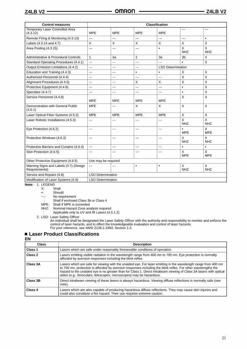
Control measures ClassificationTemporary Laser Controlled Area(4.3.12)
MPE
MPE
MPE
MPE--- ---
Remote Firing & Monitoring (4.3.13) --- --- --- --- ---
Labels (4.3.14 and 4.7) X X X X X X
Area Posting (4.3.15) --- --- --- XNHZ
XNHZ
Administrative & Procedural Controls 1 2a 2 3a 3b 4
Standard Operating Procedures (4.4.1) --- --- --- --- X
Output Emission Limitations (4.4.2) --- --- --- LSO Determination
Education and Training (4.4.3) --- --- X X
Authorized Personnel (4.4.4) --- --- --- --- X X
Alignment Procedures (4.4.5) --- --- X X X X
Protective Equipment (4.4.6) --- --- --- --- X
Spectator (4.4.7) --- --- --- --- X
Service Personnel (4.4.8)
MPE
MPE
MPE
MPEX X
Demonstration with General Public(4.5.1)
MPE --- X X X X
Laser Optical Fiber Systems (4.5.2) MPE MPE MPE MPE X X
Laser Robotic Installations (4.5.3) --- --- --- --- X NHZ
X NHZ
Eye Protection (4.6.2) --- --- --- ---
MPEXMPE
Protective Windows (4.6.3) --- --- --- --- X NHZ
X NHZ
Protective Barriers and Curtains (4.6.4) --- --- --- ---
Skin Protection (4.6.5) --- --- --- --- X MPE
X MPE
Other Protective Equipment (4.6.5) Use may be required
Warning Signs and Labels (4.7) (DesignRequirements)
--- --- X NHZ
X NHZ
Service and Repairs (4.8) LSO Determination
Modification of Laser Systems (4.9) LSO Determination
Note: 1. LEGENDX: Shall: Should---: No requirement: Shall if enclosed Class 3b or Class 4MPE: Shall if MPE is exceededNHZ: Nominal Hazard Zone analysis required: Applicable only to UV and IR Lasers (4.5.1.2)
2. LSO: Laser Safety OfficerAn individual shall be designated the Laser Safety Officer with the authority and responsibility to monitor and enforce thecontrol of laser hazards, and to effect the knowledgeable evaluation and control of laser hazards.For your reference, see ANSI Z136.1-1993, Section 1.3.
Laser Product ClassificationsEN
Class Description
Class 1 Lasers which are safe under reasonably foreseeable conditions of operation.
Class 2 Lasers emitting visible radiation in the wavelength range from 400 nm to 700 nm. Eye protection is normallyafforded by aversion responses including the blink reflex.
Class 3A Lasers which are safe for viewing with the unaided eye. For laser emitting in the wavelength range from 400 nmto 700 nm, protection is afforded by aversion responses including the blink reflex. For other wavelengths thehazard to the unaided eye is no greater than for Class 1. Direct intrabeam viewing of Class 3A lasers with opticalaides (e.g., binoculars, telescopes, microscopes) may be hazardous.
Class 3B Direct intrabeam viewing of these lasers is always hazardous. Viewing diffuse reflections is normally safe (seenote).
Class 4 Lasers which are also capable of producing hazardous diffuse reflections. They may cause skin injuries andcould also constitute a fire hazard. Their use requires extreme caution.
Z4LB V2 Z4LB V2
22
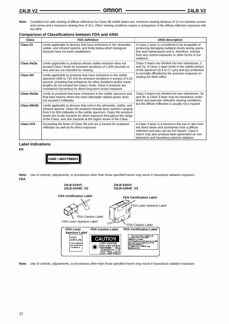
Note: Conditions for safe viewing of diffuse reflections for Class 3B visible lasers are: minimum viewing distance of 13 cm between screenand cornea and a maximum viewing time of 10 s. Other viewing conditions require a comparison of the diffuse reflection exposure withthe MPE.
Comparison of Classifications between FDA and ANSIClass FDA definition ANSI description
Class I/1 Limits applicable to devices that have emissions in the ultraviolet,visible, and infrared spectra, and limits below which biologicalhazards have not been established.
A Class 1 laser is considered to be incapable ofproducing damaging radiation levels during opera-tion and maintenance and is, therefore, exemptfrom any control measures or other forms of sur-veillance.
Class IIa/2a Limits applicable to products whose visible emission does notexceed Class I limits for emission durations of 1,000 seconds orless and are not intended for viewing.
Class 2 lasers are divided into two subclasses, 2and 2a. A Class 2 laser emits in the visible portionof the spectrum (0.4 to 0.7 µm) and eye protectioni ll ff d d b th i iClass II/2 Limits applicable to products that have emissions in the visible
spectrum (400 to 710 nm) for emission durations in excess of 0.25second, providing that emissions for other durations and/or wave-lengths do not exceed the Class I limits. Class II products areconsidered hazardous for direct long-term ocular exposure.
( µ ) yis normally afforded by the aversion response in-cluding the blink reflex.
Class IIIa/3a Limits to products that have emissions in the visible spectrum andthat have beams where the total collectable radiant power doesnot exceed 5 milliwatts.
Class 3 lasers are divided into two subclasses, 3aand 3b. A Class 3 laser may be hazardous underdirect and specular reflection viewing conditions,b t th diff fl ti i ll t h dClass IIIb/3b Limits applicable to devices that emit in the ultraviolet, visible, and
infrared spectra. Class IIIb products include laser systems rangingfrom 5 to 500 milliwatts in the visible spectrum. Class IIIb emissionlevels are ocular hazards for direct exposure throughout the rangeof the Class, and skin hazards at the higher levels of the Class.
g ,but the diffuse reflection is usually not a hazard.
Class IV/4 Exceeding the limits of Class IIIb and are a hazard for scatteredreflection as well as for direct exposure.
A Class 4 laser is a hazard to the eye or skin fromthe direct beam and sometimes from a diffusereflection and also can be fire hazard. Class 4lasers may also produce laser-generated air con-taminants and hazardous plasma radiation.
Label IndicationsEN
Note: Use of controls, adjustments, or procedures other than those specified herein may result in hazardous radiation exposure.FDA
FDA Certification Label
Z4LB-S10V2Z4LB-A1040V2
FDA Caution Label
FDA Laser Aperture Label
FDA Certification Label
FDA Caution Label
FDA Laser Aperture Label
FDA LaserAperture Label
FDA Caution Label FDA Certification Label
Z4LB-S30V2Z4LB-A3040V2
44650
Note: Use of controls, adjustments, or procedures other than those specified herein may result in hazardous radiation exposure.

Z4LB V2 Z4LB V2
23
Z4LB V2 Z4LB V2
24
The product has been produced at OMRON Ayabe which obtained ISO9001-approval for its quality systemand ISO14001-approval for its environmental management system from international certification bodies.
OMRON CorporationIndustrial Automation Company
Industrial Sensors DivisionSensing Devices and Components Division H.Q.28th Fl., Crystal Tower Bldg.,1-2-27, Shiromi, Chuo-ku,Osaka 540-6028 JapanTel: (81)6-6949-6012/Fax: (81)6-6949-6021
ALL DIMENSIONS SHOWN ARE IN MILLIMETERS.To convert millimeters into inches, multiply by 0.03937. To convert grams into ounces, multiply by 0.03527.
Cat. No. F051-E1-1A In the interest of product improvement, specifications are subject to change without notice.
Printed in Japan0400-1M (1099) a


![TAKEX PHOTOELECTRIC BEAM SENSOR lANTl-CRAWL] PB-lN](https://img.pdfslide.us/doc/110x75/58a2f00d1a28ab1f238bf6e0/takex-photoelectric-beam-sensor-lantl-crawl-pb-ln-.jpg)