Embed Size (px)
Citation preview
Mineral Insulated Stainless Steel &
Alloy Sheathed Thermocouples &
Transducer Cables & Probes
(Edition August 2017)
MICC Ltd Temperature House, 21 Sedling Road Wear Industrial Estate, Washington Tyne and Wear. UK
Tel: +44 (0) 191 416 8884 Fax: +44 (0) 191 419 2345 Email: [email protected]

The MICC Group would like to thank you for your interest in our products and we hope that this brochure enlightens you further on our range of Mineral Insulated Heating Units and Cables. MICC is the UK’s largest and only manufacturer of a full range of mineral insulated cable products. With a strong legacy dating back to the period of BICC’s reign of the cabling industry, with the Directors and senior managers previous employees of BICC. We lead the World by manufacturing to the original BICC seamless tube techniques, specialising in MI cable for multiple purposes. In addition it has been proven to be the only true fire survival cable on the market, guaranteeing over 3 hours of circuit continuity providing enough escape time in the harshest of fires. We work with a range of global clients providing MI fire survival cable to include high rise buildings, tunnels, metro systems, hospitals and refuge shelters. With the same experienced prior BICC specialists, we transform our Mineral Insulated cable into installable products and units, specialising in trace heating used to raise or maintain temperatures. Providing our leading trace heating systems for a range of sectors to include pipelines, tanks, rock crushers to car park ramps and helicopter pads. In addition MICC specialises in temperature measurement producing industrial thermocouples and RTDs measuring temperatures up to 1200°c! Shipped around the world for pipelines, steel foundries, and Nuclear power station boilers. We are also hazardous area specialists with wide range of approvals for Global operation. MICC’s Manufacturing Equipment Division is a leading global manufacturer of solutions for improving the efficiency and automation of Temperature sensor manufacture. MICC are passionate about Mineral Insulated cable R&D, our dedicated team comes up with new products and services by working closely with our clients to produce solutions on their bespoke and specialist needs; we help them save time, reduce costs and increase profit! Our many years of experience has positioned us a truly Global player, working with the some of the World’s best known companies across a wide range of sectors, including; Oil & Gas, Automotive, General Engineering, Chemical, Commercial Buildings, Metro Systems, Airports, Hospitals, Prisons, and power generation including Nuclear and Concentrated Solar Power (CSP).

Mineral insulated thermocouple probes and cables manufactured by MICC group of companies are made up of a metal conductor embedded in a compacted Magnesium oxide (inorganic) insulant inside a metal sheath. The inorganic nature of the construction enables the cables to operate at high temperatures for long periods of time in extremely harsh environments e.g. petro-chemical, reactor vessels and other applications where the integrity of the cable is most important. Operating temperatures: Operating temperatures is determined by operational temperature of the thermocouple materials and sheath material, whichever is lower. Cable with corrosion resistant grades of stainless steel and nickel alloys sheath typically up to 600°C – 900°C Cable with heat resistant stainless steel and nickel alloys sheath typically up to 1000°C – 1300°C
Thermocouple cable Sheath material: one of the following:
Transducer cable
304 – AISI 304 Stainless Steel 321 – AISI 321 Stainless Steel 310 – AISI 310S Stainless Steel 316L – AISI 316 Low Carbon Stainless Steel 316Ti – AISI 316 Titanium Stabilised Stainless Steel 347 – AISI 347 Stainless Steel 446 – AISI 446 Stainless Steel 600 – Inconel 600 601 – Alloy 601 625 – Alloy 625 NIC – Nicrobell Other materials on request No. of conductors: one of the following:
304 – AISI 304 Stainless Steel 321 – AISI 321 Stainless Steel 310 – AISI 310S Stainless Steel 316L – AISI 316 Low carbon Stainless Steel 316Ti – AISI 316 Ti stabilised Stainless Steel Other materials on request
Two conductors Four conductors Six conductors
Conductor materials:
Two conductors Three conductors Four conductors Six conductors
One of the following thermocouple types: K, N, J, E, T
Copper Nickel Other materials on request
Conductor configurations:
Alternating as standard Adjacent on request
Evenly spaced Wide spaced
Insulation material: Magnesium Oxide (MgO). Other materials on request
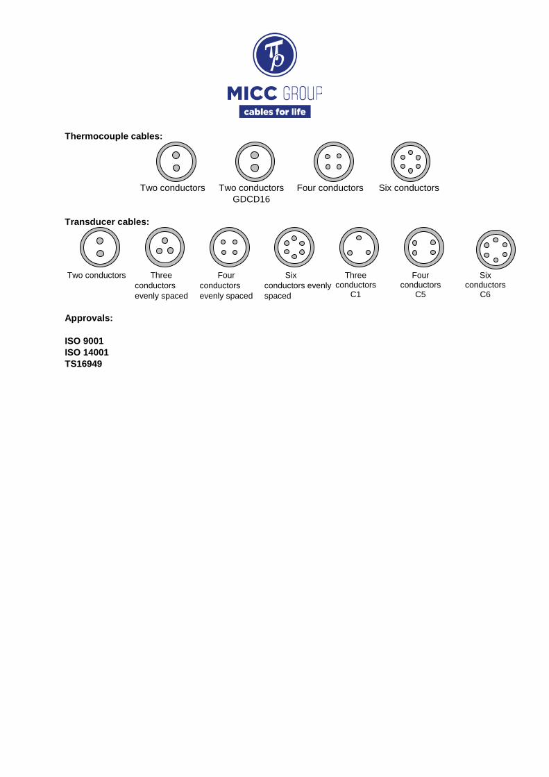
Thermocouple cables:
Two conductors Two conductors Four conductors Six conductors
GDCD16 Transducer cables:
Two conductors Three
conductors evenly spaced
Four conductors evenly spaced
Six conductors evenly spaced
Three conductors
C1
Four conductors
C5
Six conductors
C6 Approvals: ISO 9001 ISO 14001 TS16949

Thermocouple Junction Types
IJ - Insulated junction. BJ - Bonded or grounded junction. EJ Exposed junction Conductors welded together and Conductors and sheath welded Conductors welded together and insulated from sheath together exposed outside sheath closure Main Thermocouple Probe Design Types
With plain pot
With transmitter mounting plate Other designs on request Ordering information: To order please specify the following:
- Part reference (see example) - Design lengths specified in mm, including immersion length and tail length. - Type of junction - Any accessories required e.g. lock nuts or termination glands. - Any special design and test
requirements.
With 8 mm ISO seal Can be supplied with 8 mm ISO locknuts to terminate the thermocouple if necessary

Thermocouple Probes and Cable Reference Description
Category “P” – Thermocouple Probe
“T” – Thermocouple cable Number of conductors
2 – Two conductors (Simplex) 4 – Four conductors (Duplex) 6– Six conductors (Triplex)
Thermocouple Type “K” – Type K EN 60584-1 / ASTME230-03
“N” – Type N EN 60584-1 / ASTME230-03 “J” – Type J EN 60584-1 / ASTME230-03 “T” – Type T EN 60584-1 / ASTME230-03 “E” – Type E EN 60584-1 / ASTME230-03
Sheath material “321” – AISI 321 Stainless Steel
“310” – AISI 310S Stainless Steel “316L” – AISI 316L Stainless Steel “316Ti” – AISI 316Ti Stainless Steel “446” – AISI 446 Stainless Steel “600” – Inconel 600 “NIC” – Nicrobell duty 500V
Cable Diameter
2 or 3 digits metric range in 1/10 mm 4 digits imperial range in 1/1000 inch
Thermocouple Class Tolerances
“S” – Class 1 EN 60585-2 “SS” – ½ Class 1 EN 60585-2 “A” – Special Limit ASTM E230-03
Additional features “Al2O3” – Alumina insulation
“GD” – Design compliant with GDCD16 “MW” – Sheath thickness 20% OD min “TW” – Sheath thickness 25% OD min “ASTM” – MgO to ASTM1652-03” – Nickel

RTD Probe Design Types
Three-wire with solid tails and gland
Four-wire with flexible tail Ordering information: To order please specify the following:
- Part reference (see example) - Design lengths specified in mm, including immersion length, route length and tail length.
- Tail type - Seal type - Any accessories required e.g. termination glands. - Any special design and test
requirements. Tail type
Type Configuration Colour code PTFE insulated
flexible 3 wire 2 Red & 1 White 4 wire 2 Red & 2 White
PTFE insulated solid
3 wire 2 Red & 1 White 4 wire 2 Red & 2 White
3 wire & earth tail 2 Red, 1 White, & 1 Yellow/Green Seal type Termination fittings
Fitting Type Tail type Crimp Plain 3 wire flexible
Silver solder
Plain 4 wire flexible Plain 3 wire solid Plain 4 wire solid
Earth tail 3 wire & earth tail solid
Reference Material Fitting size TGMV4516
Brass 16 mm ISO Metric TGMV6016
TGMV4520 20 mm ISO Metric TGMV6020 TGMV4516
Stainless Steel
16 mm ISO Metric TGMV6016 TGMV4520 20 mm ISO Metric TGMV6020
Notes. RTD probes manufactured to BS EN60751-2008 (IEC751). Tolerance classes are to BS EN60751-2008. Minimum immersion length = 100mm. Standard tail length = 150mm Maximum operating temperature = 550 C Minimum operating temperature: Grade A = -196 C, Grade B = 0 C

Resistance Thermometers and Transducer
Cable Reference
Description Category “P” – Premium grade probe
“T” – Commercial grade probe “R” – Transducer cable
Number of conductors 2 – Two conductors (Simplex)
4 – Four conductors (Duplex) 6– Six conductors (Triplex)
Conductors material “C” – Copper “D” – Nickel
“A” – Nichrome “W” – AISI 310
Sheath “321” – AISI 321 Stainless Steel material “316L” – AISI 316L Stainless Steel
“316Ti” – AISI 316Ti Stainless Steel
Cable 2 or 3 digits metric range in 1/10 mm Diameter 4 digits imperial range in 1/1000 inch RTD Class Tolerances “A” – Class A to EN 60751 (probes only) “B” – Class B to EN 60751 Additional “C1” – 3 conductors wide spaced features “C5” – 4 conductors wide spaced
“C6” – 6 conductors wide spaced “SP” – special design
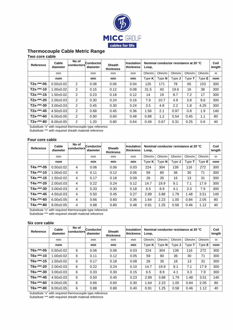
Thermocouple Cable Metric Range Two core cable
Reference Cable diameter
No of conductors Conductor
diameter
Sheath thickness
Insulation thickness
Nominal conductor resistance at 20 °C Loop,
Coil length
mm mm mm mm Ohm/m Ohm/m Ohm/m Ohm/m Ohm/m m nom min min min Type K Type N Type J Type T Type E nom
T2x-***-05 0.50±0.02 2 0.08 0.06 0.04 126 171 78 65 153 300 T2x-***-10 1.00±0.02 2 0.15 0.12 0.08 31.5 43 19.6 16 38 300 T2x-***-15 1.50±0.02 2 0.23 0.18 0.12 14 19 8.7 7.2 17 300 T2x-***-20 2.00±0.03 2 0.30 0.24 0.16 7.9 10.7 4.9 3.8 9.6 300 T2x-***-30 3.00±0.03 2 0.45 0.30 0.24 3.5 4.8 2.2 1.8 4.25 300 T2x-***-45 4.50±0.03 2 0.68 0.45 0.36 1.56 2.1 0.97 0.8 1.9 140 T2x-***-60 6.00±0.05 2 0.90 0.60 0.48 0.88 1.2 0.54 0.45 1.1 80 T2x-***-80 8.00±0.05 2 1.20 0.80 0.64 0.49 0.67 0.31 0.25 0.6 40 Substitute “x” with required thermocouple type reference Substitute *** with required sheath material reference
Four core cable
Reference Cable diameter
No of conductors Conductor
diameter
Sheath thickness
Insulation thickness
Nominal conductor resistance at 20 °C Loop,
Coil length
mm mm mm mm Ohm/m Ohm/m Ohm/m Ohm/m Ohm/m m nom min min min Type K Type N Type J Type T Type E nom
T4x-***-05 0.50±0.02 4 0.06 0.06 0.03 224 304 139 116 272 300 T4x-***-10 1.00±0.02 4 0.11 0.12 0.06 59 80 36 30 71 300 T4x-***-15 1.50±0.02 4 0.17 0.18 0.09 26 35 16 13 31 300 T4x-***-20 2.00±0.03 4 0.22 0.24 0.12 14.7 19.9 9.1 7.1 17.9 300 T4x-***-30 3.00±0.03 4 0.33 0.30 0.18 6.5 8.9 4.1 3.3 7.9 300 T4x-***-45 4.50±0.03 4 0.50 0.45 0.27 2.89 3.88 1.79 1.48 3.51 140 T4x-***-60 6.00±0.05 4 0.66 0.60 0.36 1.64 2.23 1.00 0.84 2.05 80 T4x-***-80 8.00±0.05 4 0.88 0.80 0.48 0.91 1.25 0.58 0.46 1.12 40 Substitute “x” with required thermocouple type reference Substitute *** with required sheath material reference
Six core cable
Reference Cable diameter
No of conductors Conductor
diameter
Sheath thickness
Insulation thickness
Nominal conductor resistance at 20 °C Loop,
Coil length
mm mm mm mm Ohm/m Ohm/m Ohm/m Ohm/m Ohm/m m nom min min min Type K Type N Type J Type T Type E nom
T6x-***-05 0.50±0.02 6 0.06 0.06 0.03 224 304 139 116 272 300 T6x-***-10 1.00±0.02 6 0.11 0.12 0.05 59 80 36 30 71 300 T6x-***-15 1.50±0.02 6 0.17 0.18 0.08 26 35 16 13 31 300 T6x-***-20 2.00±0.03 6 0.22 0.24 0.10 14.7 19.9 9.1 7.1 17.9 300 T6x-***-30 3.00±0.03 6 0.33 0.30 0.15 6.5 8.9 4.1 3.3 7.9 300 T6x-***-45 4.50±0.03 6 0.50 0.45 0.23 2.89 3.88 1.79 1.48 3.51 140 T6x-***-60 6.00±0.05 6 0.66 0.60 0.30 1.64 2.23 1.00 0.84 2.05 80 T6x-***-80 8.00±0.05 6 0.88 0.80 0.40 0.91 1.25 0.58 0.46 1.12 40 Substitute “x” with required thermocouple type reference Substitute *** with required sheath material reference

Thermocouple Cable Imperial Range
Two core cable Reference Cable
diameter No of
conductors Conductor diameter
Sheath thickness
Insulation thickness Nominal conductor resistance at 20 °C Loop, Coil
length mm mm mm mm Ohm/m Ohm/m Ohm/m Ohm/m Ohm/m m nom min min min Type K Type N Type J Type T Type E nom
T2x-***-0032 0.80±0.02 2 0.12 0.10 0.06 49 67 31 25 60 300 T2x-***-0063 1.60±0.02 2 0.24 0.19 0.13 12 17 7.6 6.3 15 300 T2x-***-0125 3.20±0.03 2 0.48 0.32 0.26 3.1 4.2 1.9 1.6 3.7 300 T2x-***-0188 4.80±0.05 2 0.72 0.48 0.38 1.4 1.9 0.85 0.7 1.7 125 T2x-***-0250 6.35±0.05 2 0.95 0.64 0.51 0.78 1.1 0.49 0.4 0.95 75 T2x-***-0500 12.70±0.05 2 1.91 1.27 1.02 0.2 0.27 0.12 0.1 0.24 18
Four core cable
Reference Cable diameter
No of conductors
Conductor diameter
Sheath thickness
Insulation thickness Nominal conductor resistance at 20 °C Loop, Coil
length mm mm mm mm Ohm/m Ohm/m Ohm/m Ohm/m Ohm/m m nom min min min Type K Type N Type J Type T Type E nom
T4x-***-0032 0.80±0.02 4 0.10 0.10 0.05 77 105 48 39 94 300 T4x-***-0063 1.60±0.02 4 0.19 0.19 0.10 19 27 12 10 23 300 T4x-***-0125 3.20±0.03 4 0.38 0.32 0.19 4.8 6.6 3.0 2.5 5.8 300 T4x-***-0188 4.80±0.05 4 0.58 0.48 0.29 2.2 3.0 1.3 1.1 2.7 125 T4x-***-0250 6.35±0.05 4 0.76 0.64 0.38 1.2 1.7 0.8 0.6 1.5 75 T4x-***-0500 12.70±0.05 4 1.52 1.27 0.76 0.31 0.42 0.19 0.16 0.38 18
Six core cable
Reference Cable diameter
No of conductors
Conductor diameter
Sheath thickness
Insulation thickness Nominal conductor resistance at 20 °C Loop, Coil
length mm mm mm mm Ohm/m Ohm/m Ohm/m Ohm/m Ohm/m m nom min min min Type K Type N Type J Type T Type E nom
T6x-***-0032 0.80±0.02 0.07 0.10 0.04 224 77 105 48 39 94 0.07 T6x-***-0063 1.60±0.02 0.14 0.19 0.08 59 19 27 12 10 23 0.14 T6x-***-0125 3.20±0.03 0.29 0.32 0.16 26 4.8 6.6 3.0 2.5 5.8 0.29 T6x-***-0188 4.80±0.05 0.43 0.48 0.24 14.7 2.2 3.0 1.3 1.1 2.7 0.43 T6x-***-0250 6.35±0.05 0.57 0.64 0.32 6.5 1.2 1.7 0.8 0.6 1.5 0.57 T6x-***-0500 12.70±0.05 1.14 1.27 0.64 2.89 0.31 0.42 0.19 0.16 0.38 1.14
Substitute “x” with required thermocouple type reference Substitute *** with required sheath material reference

Transducer Cable Range Two core cable
Reference Cable diameter No of conductors
Conductor diameter
Sheath thickness
Conductors PCD
Nominal conductor resistance at 20 °C Coil length
mm mm mm mm Ohm/m Ohm/m m nom min min min R2C- R2D- nom
R2x-***-15 1.50±0.02 2 0.30 0.23 0.45 0.243 1.358 300 R2x-***-16 1.60±0.02 2 0.32 0.24 0.48 0.214 1.194 300 R2x-***-30 3.00±0.03 2 0.60 0.30 1.00 0.061 0.340 300 R2x-***-32 3.20±0.03 2 0.64 0.32 1.07 0.053 0.298 300 R2x-***-45 4.50±0.03 2 0.90 0.45 1.50 0.027 0.151 140 R2x-***-48 4.80±0.03 2 0.92 0.48 1.59 0.026 0.144 140 R2x-***-60 6.00±0.05 2 1.20 0.60 2.00 0.015 0.085 80 R2x-***-64 6.40±0.05 2 1.28 0.64 2.13 0.013 0.075 80
Substitute “x” with required transducer type reference Substitute *** with required sheath material reference
Three core evenly spaced cable Reference Cable diameter No of
conductors Conductor diameter
Sheath thickness
Conductors PCD
Nominal conductor resistance at 20 °C Coil length
mm mm mm mm Ohm/m Ohm/m m nom min min min R3C- R3D- nom
R3x-***-30 3.00±0.03 3 0.45 0.30 1.04 0.108 0.604 300 R3x-***-32 3.20±0.03 3 0.48 0.32 1.11 0.095 0.531 300 R3x-***-45 4.50±0.03 3 0.68 0.45 1.56 0.048 0.268 140 R3x-***-48 4.80±0.03 3 0.72 0.48 1.67 0.042 0.236 140 R3x-***-60 6.00±0.05 3 0.90 0.60 2.09 0.027 0.151 80 R3x-***-64 6.40±0.05 3 0.96 0.64 2.23 0.024 0.133 80
Substitute “x” with required transducer type reference Substitute *** with required sheath material reference
Four core evenly spaced cable Reference Cable diameter No of
conductors Conductor diameter
Sheath thickness
Conductors PCD
Nominal conductor resistance at 20 °C Coil length
mm mm mm mm Ohm/m Ohm/m m nom min min min R4C- R4D- nom
R4x-***-30 3.00±0.03 4 0.34 0.30 1.04 0.047 1.057 300 R4x-***-32 3.20±0.03 4 0.36 0.32 1.11 0.095 0.943 300 R4x-***-45 4.50±0.03 4 0.50 0.45 1.56 0.048 0.489 140 R4x-***-48 4.80±0.03 4 0.54 0.48 1.67 0.042 0.419 140 R4x-***-60 6.00±0.05 4 0.68 0.60 2.09 0.027 0.264 80 R4x-***-64 6.40±0.05 4 0.72 0.64 2.23 0.024 0.236 80
Substitute “x” with required transducer type reference Substitute *** with required sheath material reference

Six core evenly spaced cable
Reference Cable diameter No of
conductors Conductor diameter
Sheath thickness
Conductors PCD
Nominal conductor resistance at 20 °C Coil length
mm mm mm mm Ohm/m Ohm/m m nom min min min R4C- R4D- nom
R6x-***-30 3.00±0.03 6 0.34 0.30 1.37 0.19 1.057 300
R6x-***-32 3.20±0.03 6 0.36 0.32 1.46 0.17 0.943 300
R6x-***-45 4.50±0.03 6 0.50 0.45 2.06 0.09 0.489 140
R6x-***-48 4.80±0.03 6 0.54 0.48 2.19 0.08 0.419 140
R6x-***-60 6.00±0.05 6 0.68 0.60 2.74 0.05 0.264 80
R6x-***-64 6.40±0.05 6 0.72 0.64 2.92 0.04 0.236 80
Substitute “x” with required transducer type reference Substitute *** with required sheath material reference
Three core C1 configuration cable
Reference Cable diameter No of
conductors Conductor diameter
Sheath thickness
Conductors PCD
Nominal conductor resistance at 20 °C Coil length
mm mm mm mm Ohm/m Ohm/m m nom min min min R3C- R3D- nom
R3x-***-30-C1 3.00±0.03 3 0.34 0.30 1.62 0.19 1.057 300
R3x-***-32-C1 3.20±0.03 3 0.36 0.32 1.73 0.17 0.943 300
R3x-***-45-C1 4.50±0.03 3 0.50 0.45 2.43 0.09 0.489 140
R3x-***-48-C1 4.80±0.03 3 0.53 0.48 2.59 0.08 0.419 140
R3x-***-60-C1 6.00±0.05 3 0.68 0.60 3.24 0.05 0.264 80
R3x-***-64-C1 6.40±0.05 3 0.72 0.64 3.46 0.04 0.236 80
Substitute “x” with required transducer type reference Substitute *** with required sheath material reference
Four core C5 configuration cable
Reference Cable diameter No of
conductors Conductor diameter
Sheath thickness
Conductors PCD
Nominal conductor resistance at 20 °C Coil length
mm mm mm mm Ohm/m Ohm/m m nom min min min R4C- R4D- nom
R4x-***-30-C5 3.00±0.03 4 0.34 0.30 1.62 0.19 1.057 300
R4x-***-32-C5 3.20±0.03 4 0.36 0.32 1.73 0.17 0.943 300
R4x-***-45-C5 4.50±0.03 4 0.50 0.45 2.43 0.09 0.489 140
R4x-***-48-C5 4.80±0.03 4 0.53 0.48 2.59 0.08 0.419 140
R4x-***-60-C5 6.00±0.05 4 0.68 0.60 3.24 0.05 0.264 80
R4x-***-64-C5 6.40±0.05 4 0.72 0.64 3.46 0.04 0.236 80
Substitute “x” with required transducer type reference Substitute *** with required sheath material reference

Six core C6 configuration cable
Reference Cable diameter No of
conductors Conductor diameter
Sheath thickness
Conductors PCD
Nominal conductor resistance at 20 °C Coil length
mm mm mm mm Ohm/m Ohm/m m nom min min min R6C- R6D- nom
R6x-***-30-C6 3.00±0.03 6 0.34 0.30 1.62 0.19 1.057 300
R6x-***-32-C6 3.20±0.03 6 0.36 0.32 1.73 0.17 0.943 300
R6x-***-45-C6 4.50±0.03 6 0.50 0.45 2.43 0.09 0.489 140
R6x-***-48-C6 4.80±0.03 6 0.53 0.48 2.59 0.08 0.419 140
R6x-***-60-C6 6.00±0.05 6 0.68 0.60 3.24 0.05 0.264 80
R6x-***-64-C6 6.40±0.05 6 0.72 0.64 3.46 0.04 0.236 80
Substitute “x” with required transducer type reference Substitute *** with required sheath material reference

Thermocouple Tolerance Limits Tolerance reference junction 0°C
Type Temperature Range,
EN 60584-2 ASTM E230-03 Class 1 Class 2 Special Limit Standard Limit
K -40°C to 1000°C ±1.5°C or 0.004·t
(whichever is greater) ±2.5°C or ±0.0075·t
(whichever is greater)
0°C to 1260°C ±1.1°C or 0.004·t (whichever is greater)
±2.2°C or ±0.0075·t (whichever is greater)
N -40°C to 1000°C ±1.5°C or 0.004·t
(whichever is greater) ±2.5°C or ±0.0075·t
(whichever is greater)
0°C to 1260°C ±1.1°C or 0.004·t (whichever is greater)
±2.2°C or ±0.0075·t (whichever is greater)
J -40°C to 750°C ±1.5°C or 0.004·t
(whichever is greater) ±2.5°C or ±0.0075·t
(whichever is greater)
0°C to 760°C ±1.1°C or 0.004·t (whichever is greater)
±2.2°C or ±0.0075·t (whichever is greater)
E -40°C to 800°C ±1.5°C or 0.004·t
(whichever is greater) ±2.5°C or ±0.0075·t
(whichever is greater)
0°C to 870°C ±1.0°C or 0.004·t (whichever is greater)
±1.7°C or ±0.005·t (whichever is greater)
T -40°C to 350°C ±0.5°C or 0.004·t
(whichever is greater) ±1.0°C or ±0.0075·t
(whichever is greater)
0°C to 370°C ±0.5°C or 0.004·t (whichever is greater)
±1.0°C or ±0.0075·t (whichever is greater)
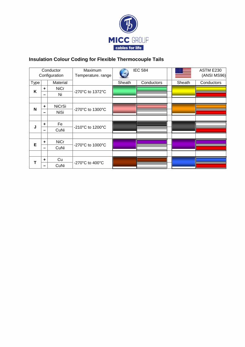
Insulation Colour Coding for Flexible Thermocouple Tails
Conductor Configuration
Maximum Temperature. range
IEC 584
ASTM E230 (ANSI MS96)
Type Material Sheath Conductors Sheath Conductors
K + NiCr
-270°C to 1372°C
– Ni
N + NiCrSi
-270°C to 1300°C
– NiSi
J + Fe
-210°C to 1200°C
– CuNi
E + NiCr
-270°C to 1000°C
– CuNi
T + Cu
-270°C to 400°C
– CuNi