Embed Size (px)
Citation preview
012-06123D
MILLIKAN OIL DROPAPPARATUS
Instruction Manual andExperiment Guide for thePASCO scientificModel AP-8210
IncludesTeacher's Notes
andTypical
Experiment Results
xxxxxx
xxxxxxxxxxxxxxxxxxxxxxxxxxxx
xxxxxxxx
xxxx
xxxx
x
i
012-06123D Millikan Oil Drop Experiment
Table of Contents
Section Page
Copyright, Warranty, and Equipment Return...........................................................ii
Introduction..............................................................................................................1–2
Equipment...............................................................................................................3– 4
Equipment Setup........................................................................................................5
Aligning the Optical System......................................................................................6
Functions of Controls.................................................................................................6
Adjusting and Measuring the Voltage.......................................................................7
Determining the Temperature of the Droplet Viewing Chamber.............................7
Experimental Procedure...........................................................................................7–9
Computation of the Charge of an Electron................................................................9
Using a Projection Microscope with the Millikan Oil Drop Apparatus...................10
Historical ................................................................................................................11–15
Maintenance Notes
Cleaning....................................................................................................................16
Replacing the Halogen Bulb.....................................................................................16
Adjusting the Vertical Reticle and Viewing Scope Alignments..............................16
Adjusting the Horizontal Reticle Alignment............................................................17
Touching Up the Black Painted Surface on the Plastic Spacer................................17
Appendix
A: Viscosity of Dry Air as a Function of Temperature.........................................19
B: Thermistor Resistance at Various Temperatures..............................................20
Teacher’s Guide....................................................................................................21–24
Technical Support............................................................................................Back Cover
012-06123D Millikan Oil Drop Experiment
1
The electric charge carried by a particle may be calculatedby measuring the force experienced by the particle in anelectric field of known strength. Although it is relativelyeasy to produce a known electric field, the force exertedby such a field on a particle carrying only one or severalexcess electrons is very small. For example, a field of1000 volts per cm would exert a force of only 1.6 l0-9
dyne on a particle bearing one excess electron. This is aforce comparable to the gravitational force on a particlewith a mass of l0-l2 (one million millionth) gram.
The success of the Millikan Oil Drop experiment dependson the ability to measure forces this small. The behaviorof small charged droplets of oil, having masses of onlyl0-12 gram or less, is observed in a gravitational and anelectric field. Measuring the velocity of fall of the drop inair enables, with the use of Stokes’ Law, the calculation ofthe mass of the drop. The observation of the velocity ofthe drop rising in an electric field then permits acalculation of the force on, and hence, the charge carriedby the oil drop.
Although this experiment will allow one to measure thetotal charge on a drop, it is only through an analysis of thedata obtained and a certain degree of experimental skillthat the charge of a single electron can be determined. Byselecting droplets which rise and fall slowly, one can becertain that the drop has a small number of excesselectrons. A number of such drops should be observedand their respective charges calculated. If the charges onthese drops are integral multiples of a certain smallestcharge, then this is a good indication of the atomic natureof electricity. However, since a different droplet has beenused for measuring each charge, there remains thequestion as to the effect of the drop itself on the charge.This uncertainty can be eliminated by changing the chargeon a single drop while the drop is under observation. Anionization source placed near the drop will accomplishthis. In fact, it is possible to change the charge on thesame drop several times. If the results of measurementson the same drop then yield charges which are integralmultiples of some smallest charge, then this is proof of theatomic nature of electricity.
The measurement of the charge of the electron alsopermits the calculation of Avogadro’s number. Theamount of current required to electrodeposit one gramequivalent of an element on an electrode (the faraday) is
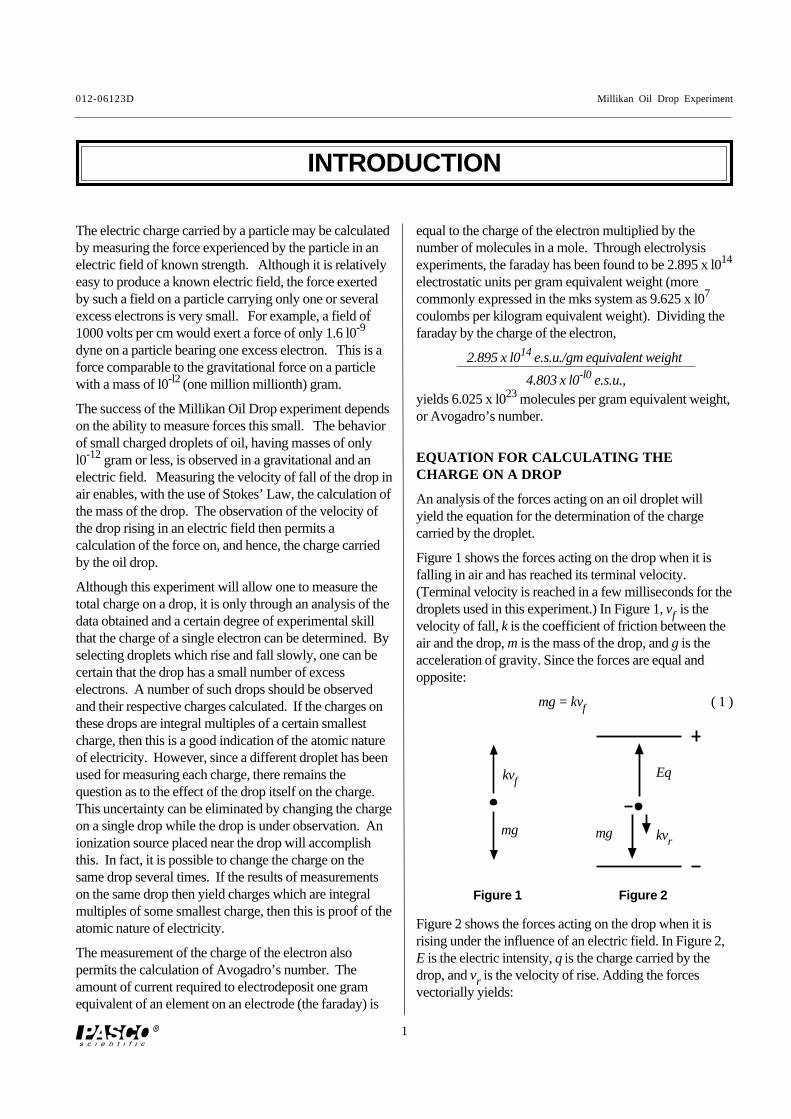
Figure 1 Figure 2
Figure 2 shows the forces acting on the drop when it isrising under the influence of an electric field. In Figure 2,E is the electric intensity, q is the charge carried by thedrop, and vr is the velocity of rise. Adding the forcesvectorially yields:
EQUATION FOR CALCULATING THECHARGE ON A DROP
An analysis of the forces acting on an oil droplet willyield the equation for the determination of the chargecarried by the droplet.
Figure 1 shows the forces acting on the drop when it isfalling in air and has reached its terminal velocity.(Terminal velocity is reached in a few milliseconds for thedroplets used in this experiment.) In Figure 1, vf is thevelocity of fall, k is the coefficient of friction between theair and the drop, m is the mass of the drop, and g is theacceleration of gravity. Since the forces are equal andopposite:
mg = kvf ( 1 )
INTRODUCTION
kvf
mg
Eq
kvrmg
equal to the charge of the electron multiplied by thenumber of molecules in a mole. Through electrolysisexperiments, the faraday has been found to be 2.895 x l014
electrostatic units per gram equivalent weight (morecommonly expressed in the mks system as 9.625 x l07
coulombs per kilogram equivalent weight). Dividing thefaraday by the charge of the electron,
2.895 x l014 e.s.u./gm equivalent weight
4.803 x l0-l0 e.s.u.,yields 6.025 x l023 molecules per gram equivalent weight,or Avogadro’s number.
Millikan Oil Drop Experiment 012-06123D
2
The electric intensity is given by E = V/d, where V is thepotential difference across the parallel plates separated bya distance d. E, V, and d are all expressed in the samesystem of units. If E is in electrostatic units, V in volts,and d in centimeters, the relationship is:
(9 )
Substituting equations ( 7 ) and ( 8 ) into equation ( 6 ) andrearranging the terms yields:
(10 )
The terms in the first set of brackets need only bedetermined once for any particular apparatus. The secondterm is determined for each droplet, while the term in thethird set of brackets is calculated for each change ofcharge that the drop experiences.
The definitions of the symbols used, together with theirproper units for use in equation ( 9 ) are***:
q – charge, in e.s.u. , carried by the dropletd – separation of the plates in the condenser in cmρ –density of oil in gm/cm3
g – acceleration of gravity in cm/s2
η –viscosity of air in poise ( dyne s/cm2)b – constant, equal to 6. 17 x l0-4 (cm of Hg) (cm)p – barometric pressure in cm of mercury.a – radius of the drop in cm as calculated by equation
( 5 )vf – velocity of fall in cm/svr – velocity of rise in cm/sV –potential difference across the plates in volts
Note: The accepted value for e is 4.803 x l0-l0 e.s.u.,or 1.60 x 10⁻¹⁹ coulombs.
( 2 )
In both cases there is also a small buoyant force exertedby the air on the droplet. Since the density of air is onlyabout one-thousandth that of oil, this force may beneglected.
Eliminating k from equations ( 1 ) and ( 2 ) and solvingfor q yields:
( 3 )
To eliminate m from equation ( 3 ), one uses theexpression for the volume of a sphere:
( 4 )
where a is the radius of the droplet, and ρ is the density ofthe oil.
To calculate a, one employs Stokes’ Law, relating theradius of a spherical body to its velocity of fall in aviscous medium (with the coefficient of viscosity, η).
*
( 5 )
Stokes’ Law, however, becomes incorrect when thevelocity of fall of the droplets is less than 0.1 cm/s.(Droplets having this and smaller velocities have radii, onthe order of 2 microns, comparable to the mean free pathof air molecules, a condition which violates one of theassumptions made in deriving Stokes’ Law.) Since thevelocities of the droplets used in this experiment will be inthe range of 0.01 to 0.001 cm/s, the viscosity must bemultiplied by a correction factor. The resulting effectiveviscosity is:
**
( 6 )
where b is a constant, p is the atmospheric pressure, and ais the radius of the drop as calculated by the uncorrectedform of Stokes’ Law, equation ( 5 ).
Substituting ηeff in equation (6) into equation (5), andthen solving for the radius a gives:
( 7 )
Substituting equations (4), (5), and (6) into equation (3)yields:
( 8 )
*For additional information about Stokes’ Law, thestudent is referred to Introduction to Theoretical Physics,by L. Page (New York, Van Nostrand), Chapter 6.
** A derivation may be found in The Electron by R. A.Millikan (Chicago, The University of Chicago Press),Chapter 5.
*** Modern calculations of q are usually conducted in SIunits. (See Experimental Procedure, Computation of theCharge of an Electron, page 7.)
Eq = mg + kvr
q =mg (vf + vr)
Evf
a =9η vf
2gρ
m = 43πa3ρ
ηeff = η 11 + b
pa
q = 6π9η3
2gρ 1 + bpa
3 vf + vr vf
E (e.s.u.) =V (volts)
300d (cm)
q = 400πd 1gρ
9η
2
31 21 2
x 11 + b
pa
3 23 2
xvf + vr vf
V e.s.u.
012-06123D Millikan Oil Drop Experiment
3
xxxx
xxxxxxxxxxxxxxxx
PLATE VOLTAGE
500VDC MAX
+
–
CHAMBER TEMPERATURE
THERMISTOR
IONIZATION
SOURCE
IONIZATION
SOURCE
SPRAY
DROPLET
Ω
RETICLE
FOCUS
DROPLET
FOCUS
DO NOT APPLY VOLTAGE
POSITION
ON
IONIZATION
SOURCE:
THORIUM 232
0.008 µCi
xxxx
xxxx
THERMISTOR RESISTANCE TABLE
MILLIKAN OIL DROP
APPARATUS
AP-8210
VERTICAL
LAMP
ADJUSTMENT
HORIZONTAL
LAMP
ADJUSTMENT
LAMP
POWER
REMOVE
SCREWS TO
REPLACE BULB
103.239
113.118
123.004
133.897
142.795
152.700
162.610
172.526
182.446
192.371
202.300
212.233
222.169
232.110
242.053
252.000
261.950
271.902
281.857
291.815
301.774
311.736
321.700
331.666
341.634
351.603
361.574
371.547
381.521
391.496
°CX106
Ω
°CX106
Ω
°CX106
Ω
UNSCREW TO
USE REPLACEMENT
HALOGEN BULB
PASCO P/N 526-037
12V, 5W
FOCUSING
WIRE
PLATE
VOLTAGETOP
PLATE
–
PLATES
GROUNDED
TOP
PLATE
+
x
xxxx
EQUIPMENT
Included equipment:
• apparatus platform and plate charging switch (seedetailed description below and on page 4)
• 12 volt DC transformer for the halogen lamp
• non-volatile oil (Squibb #5597 Mineral Oil, density =886 kg/m3)*
• atomizer
* Note: We measured the density of the Squibb MineralOil and found it to be 886kg/m3. However, thedensities of different lots of mineral oil may varyslightly; therefore, for greatest precision, you shoulddetermine the density of the mineral oil you are using.
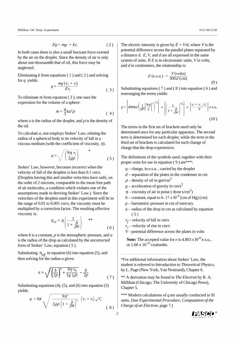
Figure 3. Included equipment
platform
atomizer
12 V DCpower
adaptor
oil
plate charging switch
support rod clamping screw
plate voltage connectors
droplet viewing chamber housing
viewing scopereticle focusing ring
droplet focusing ring
plate charging switch
support rod mount
focusing wire
thermistor resistance table
thermistor connectors
bubble level
support rod mount
support rod clamping screw
filament adjustment knob (horizontal)
filament adjustment knob(vertical)
convex lens
Figure 4. Apparatus platform
halogen lamp housing
lamp power jack
ionization source lever
Millikan Oil Drop Experiment 012-06123D
4
Required equipment, not included:• high voltage, well regulated power supply that
delivers up to 500 V DC, 10 mA minimum (forexample, the PASCO SF-9585 High Voltage PowerSupply)
• digital multimeter (to measure voltage and resistance)(for example, the PASCO SB-9599A UniversalDigital Multimeter)
• patch cords with banana plug connectors (4) (forexample, the PASCO SE-9415 Banana Plug PatchCord)
• stopwatch (for example, the PASCO SE-8702ADigital Stopwatch)
Additional recommended equipment:
• PASCO ME-8735 Large Rod Stand
• PASCO ME-8736 Steel Rods, 45 cm (2)
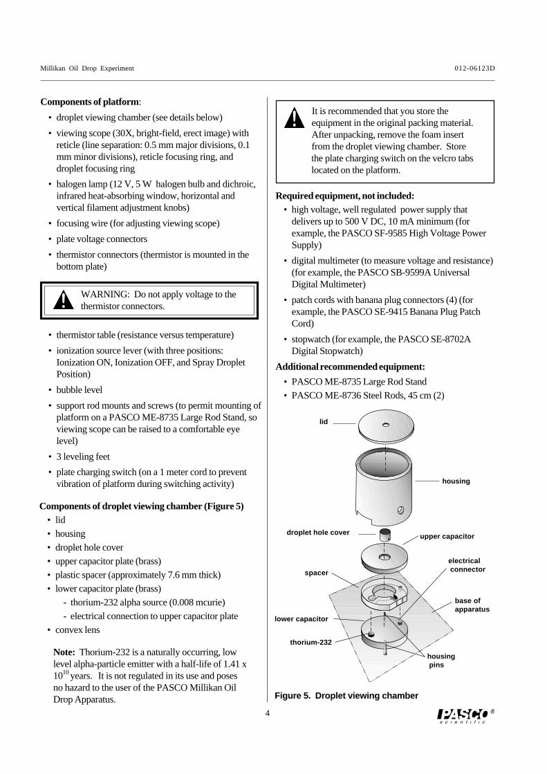
Components of droplet viewing chamber (Figure 5)• lid
• housing
• droplet hole cover
• upper capacitor plate (brass)
• plastic spacer (approximately 7.6 mm thick)
• lower capacitor plate (brass)
- thorium-232 alpha source (0.008 mcurie)
- electrical connection to upper capacitor plate
• convex lens
Components of platform:
• droplet viewing chamber (see details below)
• viewing scope (30X, bright-field, erect image) withreticle (line separation: 0.5 mm major divisions, 0.1mm minor divisions), reticle focusing ring, anddroplet focusing ring
• halogen lamp (12 V, 5 W halogen bulb and dichroic,infrared heat-absorbing window, horizontal andvertical filament adjustment knobs)
• focusing wire (for adjusting viewing scope)
• plate voltage connectors
• thermistor connectors (thermistor is mounted in thebottom plate)
Note: Thorium-232 is a naturally occurring, lowlevel alpha-particle emitter with a half-life of 1.41 x10¹⁰ years. It is not regulated in its use and posesno hazard to the user of the PASCO Millikan OilDrop Apparatus.
• thermistor table (resistance versus temperature)
• ionization source lever (with three positions:Ionization ON, Ionization OFF, and Spray DropletPosition)
• bubble level
• support rod mounts and screws (to permit mounting ofplatform on a PASCO ME-8735 Large Rod Stand, soviewing scope can be raised to a comfortable eyelevel)
• 3 leveling feet
• plate charging switch (on a 1 meter cord to preventvibration of platform during switching activity)
Figure 5. Droplet viewing chamber
thorium-232
upper capacitor
housing pins
droplet hole cover
lower capacitor
lid
housing
spacer
electrical connector
base ofapparatus
It is recommended that you store theequipment in the original packing material.After unpacking, remove the foam insertfrom the droplet viewing chamber. Storethe plate charging switch on the velcro tabslocated on the platform.
WARNING: Do not apply voltage to thethermistor connectors.
012-06123D Millikan Oil Drop Experiment
5
xxxxxxx
xxxx
x
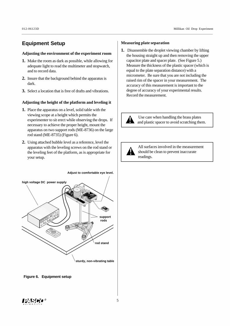
Equipment Setup
Figure 6. Equipment setup
Measuring plate separation
1. Disassemble the droplet viewing chamber by liftingthe housing straight up and then removing the uppercapacitor plate and spacer plate. (See Figure 5.)Measure the thickness of the plastic spacer (which isequal to the plate separation distance) with amicrometer. Be sure that you are not including theraised rim of the spacer in your measurement. Theaccuracy of this measurement is important to thedegree of accuracy of your experimental results.Record the measurement.
Adjusting the height of the platform and leveling it
1. Place the apparatus on a level, solid table with theviewing scope at a height which permits theexperimenter to sit erect while observing the drops. Ifnecessary to achieve the proper height, mount theapparatus on two support rods (ME-8736) on the largerod stand (ME-8735) (Figure 6).
2. Using attached bubble level as a reference, level theapparatus with the leveling screws on the rod stand orthe leveling feet of the platform, as is appropriate foryour setup.
Adjusting the environment of the experiment room
1. Make the room as dark as possible, while allowing foradequate light to read the multimeter and stopwatch,and to record data.
2. Insure that the background behind the apparatus isdark.
3. Select a location that is free of drafts and vibrations.
Adjust to comfortable eye level.
high voltage DC power supply
sturdy, non-vibrating table
support rods
rod stand
Use care when handling the brass platesand plastic spacer to avoid scratching them.
All surfaces involved in the measurementshould be clean to prevent inaccuratereadings.
Millikan Oil Drop Experiment 012-06123D
6
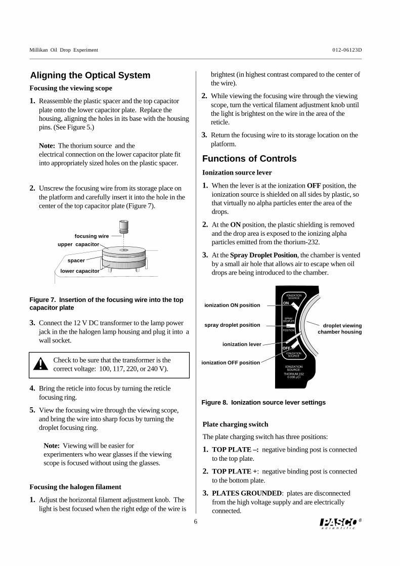
Functions of Contr olsIonization source lever
1. When the lever is at the ionization OFF position, theionization source is shielded on all sides by plastic, sothat virtually no alpha particles enter the area of thedrops.
2. At the ON position, the plastic shielding is removedand the drop area is exposed to the ionizing alphaparticles emitted from the thorium-232.
3. At the Spray Droplet Position, the chamber is ventedby a small air hole that allows air to escape when oildrops are being introduced to the chamber.
Plate charging switch
The plate charging switch has three positions:
1. TOP PLATE –: negative binding post is connectedto the top plate.
2. TOP PLATE + : negative binding post is connectedto the bottom plate.
3. PLATES GROUNDED: plates are disconnectedfrom the high voltage supply and are electricallyconnected.
3. Connect the 12 V DC transformer to the lamp powerjack in the the halogen lamp housing and plug it into awall socket.
Focusing the halogen filament
1. Adjust the horizontal filament adjustment knob. Thelight is best focused when the right edge of the wire is
Focusing the viewing scope
1. Reassemble the plastic spacer and the top capacitorplate onto the lower capacitor plate. Replace thehousing, aligning the holes in its base with the housingpins. (See Figure 5.)
Figure 7. Insertion of the focusing wire into the topcapacitor plate
Aligning the Optical System brightest (in highest contrast compared to the center ofthe wire).
2. While viewing the focusing wire through the viewingscope, turn the vertical filament adjustment knob untilthe light is brightest on the wire in the area of thereticle.
3. Return the focusing wire to its storage location on theplatform.
2. Unscrew the focusing wire from its storage place onthe platform and carefully insert it into the hole in thecenter of the top capacitor plate (Figure 7).
Note: The thorium source and theelectrical connection on the lower capacitor plate fitinto appropriately sized holes on the plastic spacer.
Check to be sure that the transformer is thecorrect voltage: 100, 117, 220, or 240 V).
4. Bring the reticle into focus by turning the reticlefocusing ring.
5. View the focusing wire through the viewing scope,and bring the wire into sharp focus by turning thedroplet focusing ring.
ionization ON position
droplet viewingchamber housing
ionization OFF position
ionization lever
IONIZATIONSOURCE
IONIZATIONSOURCE
SPRAYDROPLET
POSITION
ON
IONIZATIONSOURCE
IONIZATIONSOURCE:
THORIUM 2320.008 µCi
spray droplet position
Figure 8. Ionization source lever settings
focusing wire
upper capacitor
spacer
lower capacitor
Note: Viewing will be easier forexperimenters who wear glasses if the viewingscope is focused without using the glasses.
012-06123D Millikan Oil Drop Experiment
7
Adjusting and Measuring theVolta ge
1. Connect the high voltage DC power supply to theplate voltage connectors using banana plug patchcords and adjust to deliver about 500 V.
2. Use the digital multimeter to measure the voltagedelivered to the capacitor plates.
Determining the Temperature of theDroplet Vie wing Chamber
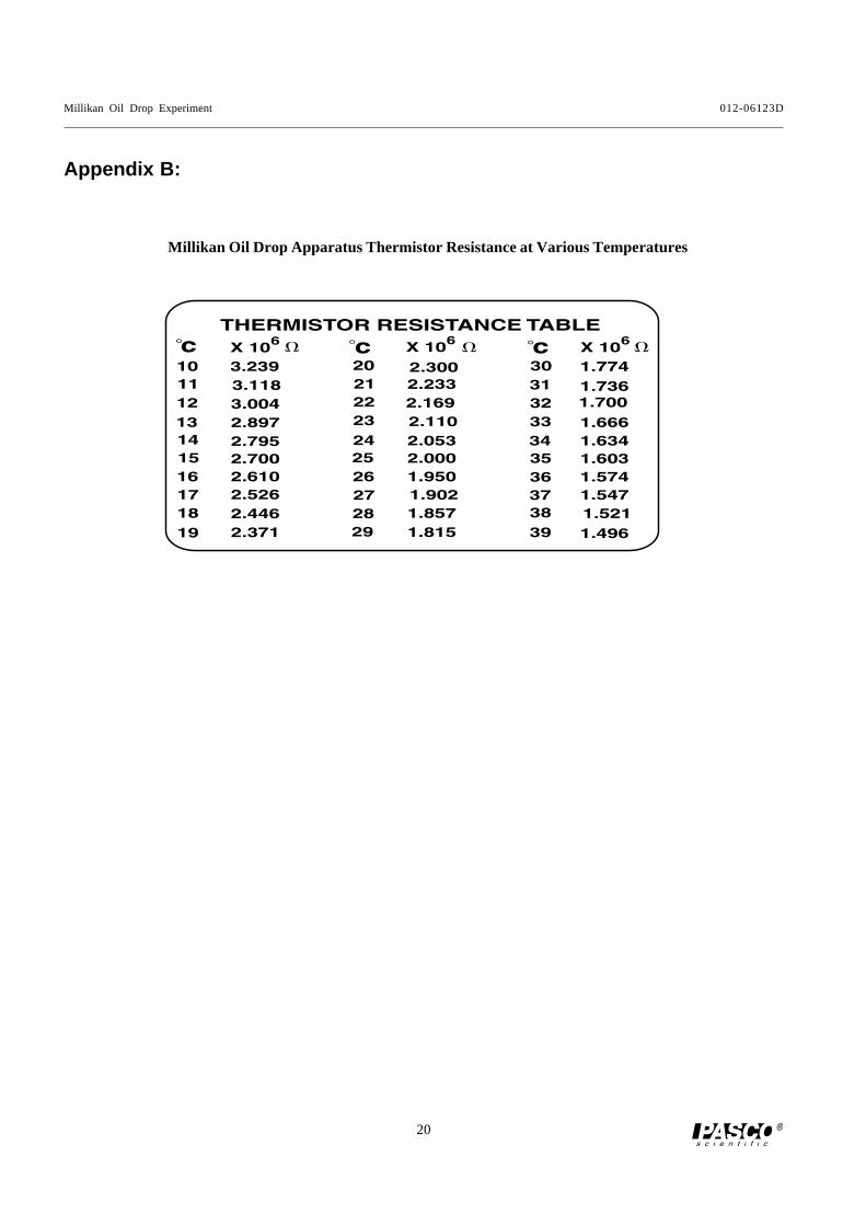
1. Connect the multimeter to the thermistor connectorsand measure the resistance of the thermistor. Refer tothe Thermistor Resistance Table located on theplatform to find the temperature of the lower brassplate. The measured temperature should correspond tothe temperature within the droplet viewing chamber.
Experimental Pr ocedure
1. Complete the reassembly of the droplet viewingchamber by placing the droplet hole cover on thetop capacitor plate and then placing the lid on thehousing. (See Figure 5.)
Introducing the droplets into the chamber
1. Put non-volatile oil of known density into the atomizer(for example, Squibb #5597 Mineral Oil, density: 886kg/m3).
2. Prepare the atomizer by rapidly squeezing the bulbuntil oil is spraying out. Insure that the tip of theatomizer is pointed down (90° to the shaft; see Figure9).
3. Move the ionization source lever to the Spray DropletPosition to allow air to escape from the chamberduring the introduction of droplets into the chamber.
4. Place the nozzle of the atomizer into the hole on the lidof the droplet viewing chamber.
5. While observing through viewing scope, squeeze theatomizer bulb with one quick squeeze. Then squeezeit slowly to force the droplets through the hole in thedroplet hole cover, through the droplet entry hole inthe top capacitor plate, and into the space between thetwo capacitor plates.
6. When you see a shower of drops through the viewingscope, move the ionization source lever to the OFFposition.
Note: The droplet hole cover prevents additionaldroplets from entering the chamber once theexperiment has started.
2. Measure and record the plate voltage and thethermistor resistance (temperature).
Figure 9. Correct position of the atomizer tip
tip
shaft
Measure the voltage at the plate voltageconnectors, not across the capacitor plates.There is a 10 megohm resistor in series witheach plate to prevent electric shock.
Although the dichroic window reflectsmuch of the heat generated by the halogenbulb, the temperature inside the dropletviewing chamber may rise after prolongedexposure to the light. Therefore, thetemperature inside the droplet viewingchamber should be determined periodically(about every 15 minutes).
Millikan Oil Drop Experiment 012-06123D
8
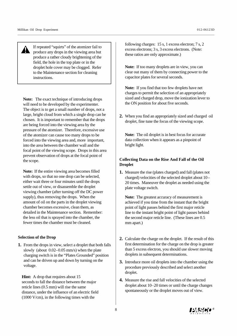
Collecting Data on the Rise And Fall of the OilDroplet
1. Measure the rise (plates charged) and fall (plates notcharged) velocities of the selected droplet about 10–20 times. Maneuver the droplet as needed using theplate voltage switch.
Note: The greatest accuracy of measurement isachieved if you time from the instant that the brightpoint of light passes behind the first major reticleline to the instant bright point of light passes behindthe second major reticle line. (These lines are 0.5mm apart.)
2. When you find an appropriately sized and charged oildroplet, fine tune the focus of the viewing scope.
Note: The oil droplet is in best focus for accuratedata collection when it appears as a pinpoint ofbright light.
Hint: A drop that requires about 15seconds to fall the distance between the majorreticle lines (0.5 mm) will rise the samedistance, under the influence of an electric field(1000 V/cm), in the following times with the
If repeated “squirts” of the atomizer fail toproduce any drops in the viewing area butproduce a rather cloudy brightening of thefield, the hole in the top plate or in thedroplet hole cover may be clogged. Referto the Maintenance section for cleaninginstructions.
Selection of the Drop
1. From the drops in view, select a droplet that both fallsslowly (about 0.02–0.05 mm/s) when the platecharging switch is in the “Plates Grounded” positionand can be driven up and down by turning on thevoltage.
Note: If the entire viewing area becomes filledwith drops, so that no one drop can be selected,either wait three or four minutes until the dropssettle out of view, or disassemble the dropletviewing chamber (after turning off the DC powersupply), thus removing the drops. When theamount of oil on the parts in the droplet viewingchamber becomes excessive, clean them, asdetailed in the Maintenance section. Remember:the less oil that is sprayed into the chamber, thefewer times the chamber must be cleaned.
Note: The exact technique of introducing dropswill need to be developed by the experimenter.The object is to get a small number of drops, not alarge, bright cloud from which a single drop can bechosen. It is important to remember that the dropsare being forced into the viewing area by thepressure of the atomizer. Therefore, excessive useof the atomizer can cause too many drops to beforced into the viewing area and, more important,into the area between the chamber wall and thefocal point of the viewing scope. Drops in this areaprevent observation of drops at the focal point ofthe scope.
Note: If too many droplets are in view, you canclear out many of them by connecting power to thecapacitor plates for several seconds.
Note: If you find that too few droplets have netcharges to permit the selection of an appropriatelysized and charged drop, move the ionization lever tothe ON position for about five seconds.
2. Calculate the charge on the droplet. If the result of thisfirst determination for the charge on the drop is greaterthan 5 excess electron, you should use slower movingdroplets in subsequent determinations.
3. Introduce more oil droplets into the chamber using theprocedure previously described and select anotherdroplet.
4. Measure the rise and fall velocities of the selecteddroplet about 10–20 times or until the charge changesspontaneously or the droplet moves out of view.
following charges: 15 s, 1 excess electron; 7 s, 2excess electrons; 3 s, 3 excess electrons. (Note:these ratios are only approximate.)
012-06123D Millikan Oil Drop Experiment
9
5. Bring the droplet to the top of the field of view andmove the ionization lever to the ON position for a fewseconds as the droplet falls.
6. If the rising velocity of the droplet changes, make asmany measurements of the new rising velocity as youcan (10 to 20 measurements).
7. If the droplet is still in view, attempt to change thecharge on the droplet by introducing more alphaparticles, as described previously, and measure thenew rising velocity 10–20 times, if possible.
8. Repeat step (7) as many times as you can.
9. Record the plate potential, the oil density, the viscosityof air at the temperature of the droplet viewingchamber, (see appendix A), and the barometric pressure for each set of velocity measurements.
Note: It is desirable to observe as many differentcharges on a single drop as possible.
Computation of the Charge of an Electron
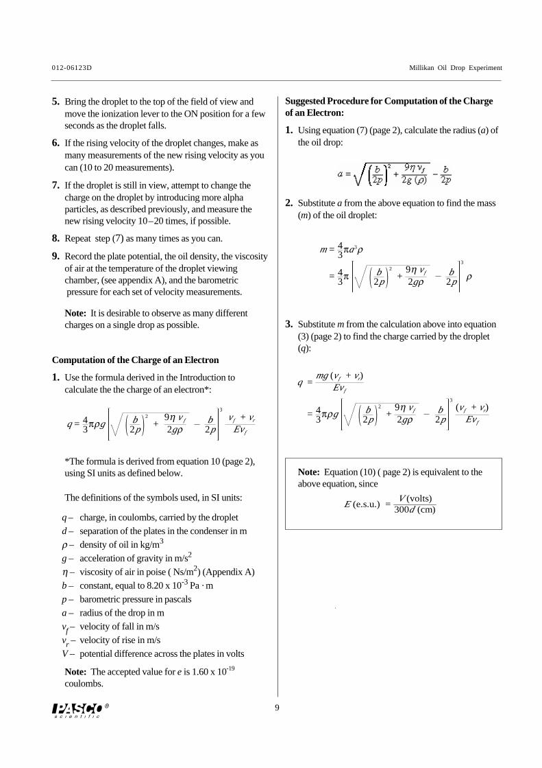
1. Use the formula derived in the Introduction tocalculate the the charge of an electron*:
*The formula is derived from equation 10 (page 2),using SI units as defined below.
The definitions of the symbols used, in SI units:
q – charge, in coulombs, carried by the droplet
d – separation of the plates in the condenser in m
ρ – density of oil in kg/m3
g – acceleration of gravity in m/s2
η – viscosity of air in poise ( Ns/m2) (Appendix A)
b – constant, equal to 8.20 x 10⁻³ Pa · m
p – barometric pressure in pascals
a – radius of the drop in m
vf – velocity of fall in m/s
vr – velocity of rise in m/s
V – potential difference across the plates in volts
Note: The accepted value for e is 1.60 x 10⁻¹⁹
coulombs.
2. Substitute a from the above equation to find the mass(m) of the oil droplet:
Suggested Procedure for Computation of the Chargeof an Electron:
1. Using equation (7) (page 2), calculate the radius (a) ofthe oil drop:
3. Substitute m from the calculation above into equation(3) (page 2) to find the charge carried by the droplet(q):
Note: Equation (10) ( page 2) is equivalent to theabove equation, since
E (e.s.u.) =V (volts)
300d (cm)
q = 43
πρg b2p
2
+9η v f
2gρb2p
3
vf + vr
Evf
m = 43
πa3ρ
= 43
π b2p
2
+9η vf
2gρb2p
3
ρ
q =mg(vf + vr)
Evf
= 43
πρg b2p
2
+9η vf
2gρb2p
3
(vf + vr)Evf
Millikan Oil Drop Experiment 012-06123D
10
Using a Pr ojecting Micr oscope withthe Millikan Oil Dr op Apparatus
To demonstrate Millikan’s experiment for an entireclassroom on a TV screen or computer monitor, use aprojecting microscope, such as the Ken-A-VisionVideoFlex Microscope (PASCO Model No. SE-7227).
Procedure:
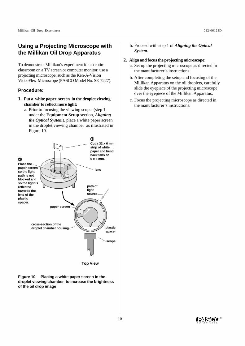
1. Put a white paper screen in the droplet viewingchamber to reflect more light:a. Prior to focusing the viewing scope (step 1
under the Equipment Setup section, Aligningthe Optical System), place a white paper screenin the droplet viewing chamber as illustrated inFigure 10.
b. Proceed with step 1 of Aligning the OpticalSystem.
2. Align and focus the projecting microscope:a. Set up the projecting microscope as directed in
the manufacturer’s instructions.
b. After completing the setup and focusing of theMillikan Apparatus on the oil droplets, carefullyslide the eyepiece of the projecting microscopeover the eyepiece of the Millikan Apparatus.
c. Focus the projecting microscope as directed inthe manufacturer’s instructions.
Figure 10. Plac ing a white paper screen in thedroplet viewing chamber to increase the brightnessof the oil drop image
Place thepaper screenso the lightpath is notblocked andso the light isreflectedtowards thelens of theplasticspacer.
Cut a 32 x 6 mmstrip of whitepaper and bendback tabs of6 x 6 mm.
lens
Top View
path oflightsource
scope
paper screen
cross-section of thedroplet chamber housing plastic
spacer
012-06123D Millikan Oil Drop Experiment
19
Appendix
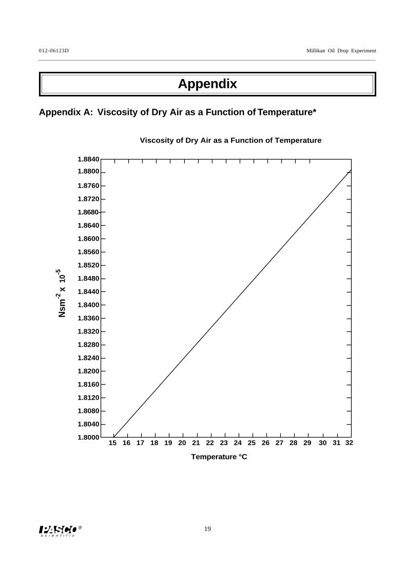
Appendix A: Viscosity of Dr y Air as a Function of Temperature*
Nsm
-2 x 1
0-5
1.8000
1.8040
1.8080
1.8120
1.8160
1.8200
1.8240
1.8280
1.8320
1.8360
1.8400
1.8440
1.8480
1.8520
1.8560
1.8600
1.8640
1.8680-
1.8720
1.8760
1.8800
1.8840
15 16 17 18 19 20 21 22 23 24 25 26 27 28 29 30 31 32
Temperature °C
Viscosity of Dry Air as a Function of Temperature
Millikan Oil Drop Experiment 012-06123D
20
Appendix B:
Millikan Oil Drop Apparatus Thermistor Resistance at Various Temperatures


![[May/June 2004] 1 (a) Shakya - GCE Compilation...3 The Millikan oil-drop experiment enabled the charge on the electron to be determined. (a) State a fundamental property of charge](https://img.pdfslide.us/doc/110x75/60bef3978d214b2af050c71e/mayjune-2004-1-a-shakya-gce-compilation-3-the-millikan-oil-drop-experiment.jpg)