Embed Size (px)
Citation preview
Page 1 of 4Installation Instructions
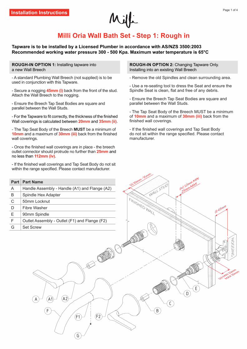
Tapware is to be installed by a Licensed Plumber in accordance with AS/NZS 3500:2003 Recommended working water pressure 300 - 500 Kpa. Maximum water temperature is 65°C
Milli Oria Wall Bath Set - Step 1: Rough in
A1 A2
F1 F2
C
DE
G
B
A
F
Part Part NameA Handle Assembly - Handle (A1) and Flange (A2)B Spindle Hex AdapterC 50mm LocknutD Fibre WasherE 90mm SpindleF Outlet Assembly - Outlet (F1) and Flange (F2)G Set Screw
ROUGH-IN OPTION 1: Installing tapware into a new Wall Breech
- A standard Plumbing Wall Breech (not supplied) is to be used in conjunction with this Tapware.
- Secure a nogging 45mm (i) back from the front of the stud. Attach the Wall Breech to the nogging.
- Ensure the Breech Tap Seat Bodies are square and parallel between the Wall Studs.
- For the Tapware to fit correctly, the thickness of the finished Wall coverings is calculated between 20mm and 35mm (ii).
- The Tap Seat Body of the Breech MUST be a minimum of 10mm and a maximum of 30mm (iii) back from the finished wall coverings.
- Once the finished wall coverings are in place - the breech outlet connector should protrude no further than 25mm and no less than 112mm (iv).
- If the finished wall coverings and Tap Seat Body do not sit within the range specified. Please contact manufacturer.
ROUGH-IN OPTION 2: Changing Tapware Only. Installing into an existing Wall Breech
- Remove the old Spindles and clean surrounding area.
- Use a re-seating tool to dress the Seat and ensure the Spindle Seat is clean, flat and free of any debris.
- Ensure the Breech Tap Seat Bodies are square and parallel between the Wall Studs.
- The Tap Seat Body of the Breech MUST be a minimum of 10mm and a maximum of 30mm (iii) back from the finished wall coverings.
- If the finished wall coverings and Tap Seat Body do not sit within the range specified. Please contact manufacturer.
Page 2 of 4Installation Instructions
E
E
D
C
C
C
E
E
E
C
E
C
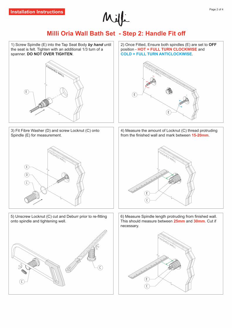
1) Screw Spindle (E) into the Tap Seat Body by hand until the seat is felt. Tighten with an additional 1/3 turn of a spanner. DO NOT OVER TIGHTEN.
3) Fit Fibre Washer (D) and screw Locknut (C) onto Spindle (E) for measurement.
5) Unscrew Locknut (C) cut and Deburr prior to re-fitting onto spindle and tightening well.
2) Once Fitted, Ensure both spindles (E) are set to OFF position - HOT = FULL TURN CLOCKWISE and COLD = FULL TURN ANTICLOCKWISE.
4) Measure the amount of Locknut (C) thread protruding from the finished wall and mark between 15-20mm.
6) Measure Spindle length protruding from finished wall. This should measure between 25mm and 30mm. Cut if necessary.
Milli Oria Wall Bath Set - Step 2: Handle Fit off
Page 3 of 4Installation Instructions
C
A1
A2
B
C
E
A1
A
A2
B
C
A1
A
E
A2
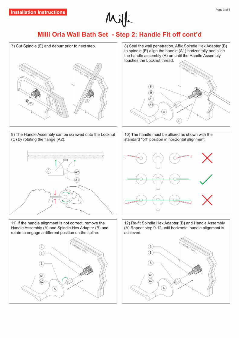
7) Cut Spindle (E) and deburr prior to next step.
9) The Handle Assembly can be screwed onto the Locknut (C) by rotating the flange (A2).
11) If the handle alignment is not correct, remove the Handle Assembly (A) and Spindle Hex Adapter (B) and rotate to engage a different position on the spline.
8) Seal the wall penetration. Affix Spindle Hex Adapter (B) to spindle (E) align the handle (A1) horizontally and slide the handle assembly (A) on until the Handle Assembly touches the Locknut thread.
10) The handle must be affixed as shown with the standard “off” position in horizontal alignment.
12) Re-fit Spindle Hex Adapter (B) and Handle Assembly (A) Repeat step 9-12 until horizontal handle alignment is achieved.
B
C
E
A1
A
A2
Milli Oria Wall Bath Set - Step 2: Handle Fit off cont’d
Page 4 of 4Installation Instructions
After installation, establish water supply and thoroughly check operation of tapware to ensure that it functions correctly and no water leaks. Plumbers, please ensure a copy of the Installation Instructions are left with the end user for future reference
Milli Oria Wall Bath Set - Step 3: Outlet Fit off
F1
F2
E
F
F2
A
A
A
A
F2A
A
F1
G
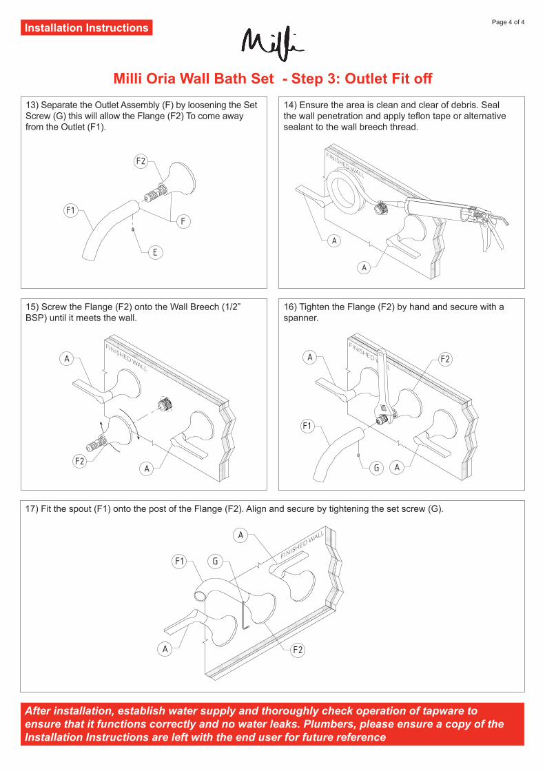
13) Separate the Outlet Assembly (F) by loosening the Set Screw (G) this will allow the Flange (F2) To come away from the Outlet (F1).
15) Screw the Flange (F2) onto the Wall Breech (1/2” BSP) until it meets the wall.
17) Fit the spout (F1) onto the post of the Flange (F2). Align and secure by tightening the set screw (G).
14) Ensure the area is clean and clear of debris. Seal the wall penetration and apply teflon tape or alternative sealant to the wall breech thread.
16) Tighten the Flange (F2) by hand and secure with a spanner.
A
A
F1 G
F2