Embed Size (px)
Citation preview
Miller Condor and NH Rear Mount Truss Boom with Enhanced Stability
Installation Manual MC2
Printed in Canada Copyright 2012 by NORAC Systems International Inc. Reorder P/N: UC4.5-BC-MC2-INST Rev A (Miller Condor and NH Rear Mount Truss Boom
with Enhanced Stability)
NOTICE: NORAC Systems International Inc. reserves the right to improve products and their specifications without notice and without the requirement to update products sold previously. Every effort has been made to ensure the accuracy of the information contained in this manual. The technical information in this manual was reviewed at the time of approval for publication.
Contents
1 Introduction ................................................................................................................ 1
2 General UC4.5 System Layout ................................................................................. 2
3 Kit Parts ...................................................................................................................... 3
4 Pre-Install Checklist ................................................................................................... 7
5 Ultrasonic Sensor Installation .................................................................................. 8
6 Roll Sensor Installation ............................................................................................ 12
7 Electrical Installation ............................................................................................... 15
8 Hydraulic Installation .............................................................................................. 18
9 Software Setup ......................................................................................................... 21
10 Cable Drawings ........................................................................................................ 22
1
1 Introduction
Congratulations on your purchase of the NORAC UC4.5 Spray Height Control System. This system is manufactured with top quality components and is engineered using the latest technology to provide operating reliability unmatched for years to come.
When properly used the system can provide protection from sprayer boom damage, improve sprayer efficiency, and ensure chemicals are applied correctly.
Please take the time to read this manual completely before attempting to install the system. A thorough understanding of this manual will ensure that you receive the maximum benefit from the system.
Your input can help make us better! If you find issues or have suggestions regarding the parts list or the installation procedure, please don’t hesitate to contact us.
Every effort has been made to ensure the accuracy of the information contained in this manual. All parts supplied are selected to specially fit the sprayer to facilitate a complete installation. However, NORAC cannot guarantee all parts fit as intended due to the variations of the sprayer by the manufacturer.
Please read this manual in its entirety before attempting installation.
2
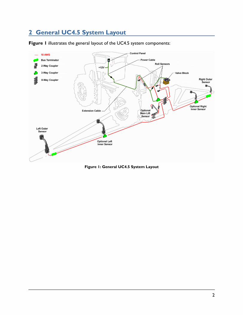
2 General UC4.5 System Layout
Figure 1 illustrates the general layout of the UC4.5 system components:
Figure 1: General UC4.5 System Layout
3
3 Kit Parts
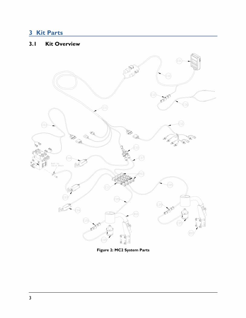
3.1 Kit Overview
Figure 2: MC2 System Parts
4
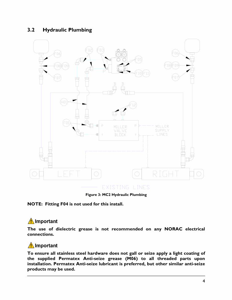
3.2 Hydraulic Plumbing
Figure 3: MC2 Hydraulic Plumbing
NOTE: Fitting F04 is not used for this install.
The use of dielectric grease is not recommended on any NORAC electrical connections.
To ensure all stainless steel hardware does not gall or seize apply a light coating of the supplied Permatex Anti-seize grease (M06) to all threaded parts upon installation. Permatex Anti-seize lubricant is preferred, but other similar anti-seize products may be used.
5
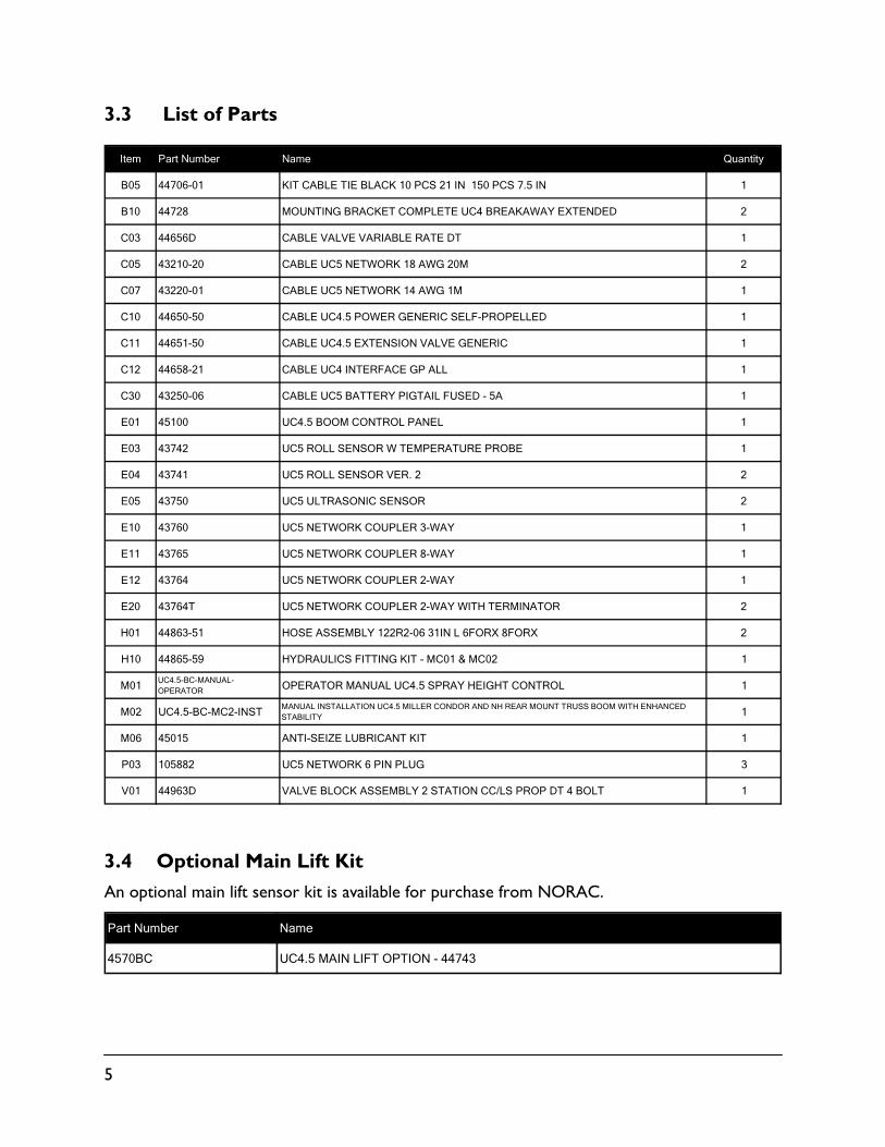
3.3 List of Parts
Item Part Number Name Quantity
B05 44706-01 KIT CABLE TIE BLACK 10 PCS 21 IN 150 PCS 7.5 IN 1
B10 44728 MOUNTING BRACKET COMPLETE UC4 BREAKAWAY EXTENDED 2
C03 44656D CABLE VALVE VARIABLE RATE DT 1
C05 43210-20 CABLE UC5 NETWORK 18 AWG 20M 2
C07 43220-01 CABLE UC5 NETWORK 14 AWG 1M 1
C10 44650-50 CABLE UC4.5 POWER GENERIC SELF-PROPELLED 1
C11 44651-50 CABLE UC4.5 EXTENSION VALVE GENERIC 1
C12 44658-21 CABLE UC4 INTERFACE GP ALL 1
C30 43250-06 CABLE UC5 BATTERY PIGTAIL FUSED - 5A 1
E01 45100 UC4.5 BOOM CONTROL PANEL 1
E03 43742 UC5 ROLL SENSOR W TEMPERATURE PROBE 1
E04 43741 UC5 ROLL SENSOR VER. 2 2
E05 43750 UC5 ULTRASONIC SENSOR 2
E10 43760 UC5 NETWORK COUPLER 3-WAY 1
E11 43765 UC5 NETWORK COUPLER 8-WAY 1
E12 43764 UC5 NETWORK COUPLER 2-WAY 1
E20 43764T UC5 NETWORK COUPLER 2-WAY WITH TERMINATOR 2
H01 44863-51 HOSE ASSEMBLY 122R2-06 31IN L 6FORX 8FORX 2
H10 44865-59 HYDRAULICS FITTING KIT - MC01 & MC02 1
M01UC4.5-BC-MANUAL-OPERATOR OPERATOR MANUAL UC4.5 SPRAY HEIGHT CONTROL 1
M02 UC4.5-BC-MC2-INSTMANUAL INSTALLATION UC4.5 MILLER CONDOR AND NH REAR MOUNT TRUSS BOOM WITH ENHANCED STABILITY 1
M06 45015 ANTI-SEIZE LUBRICANT KIT 1
P03 105882 UC5 NETWORK 6 PIN PLUG 3
V01 44963D VALVE BLOCK ASSEMBLY 2 STATION CC/LS PROP DT 4 BOLT 1
3.4 Optional Main Lift Kit
An optional main lift sensor kit is available for purchase from NORAC.
Part Number Name
4570BC UC4.5 MAIN LIFT OPTION - 44743
6
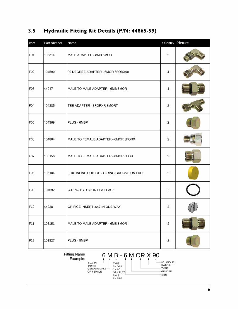
3.5 Hydraulic Fitting Kit Details (P/N: 44865-59)
Item Part Number Name Quantity Picture
F01 106314 MALE ADAPTER - 8MB 8MOR 2
F02 104590 90 DEGREE ADAPTER - 6MOR 6FORX90 4
F03 44917 MALE TO MALE ADAPTER - 6MB 6MOR 4
F04 104885 TEE ADAPTER - 8FORXR 8MORT 2
F05 104369 PLUG - 6MBP 2
F06 104884 MALE TO FEMALE ADAPTER - 6MOR 8FORX 2
F07 106156 MALE TO FEMALE ADAPTER - 8MOR 6FOR 2
F08 105184 .018" INLINE ORIFICE - O-RING GROOVE ON FACE 2
F09 104592 O-RING HYD 3/8 IN FLAT FACE 2
F10 44928 ORIFICE INSERT .047 IN ONE WAY 2
F11 105151 MALE TO MALE ADAPTER - 6MB 8MOR 2
F12 101827 PLUG - 8MBP 2
6 M B - 6 M OR X 90SIZE IN 1/16TH'S
GENDER: MALE OR FEMALE
90° ANGLESWIVELTYPEGENDERSIZE
TYPE:B - ORBJ - JICOR - FLAT FACEP - PIPE
Fitting Name Example:
7
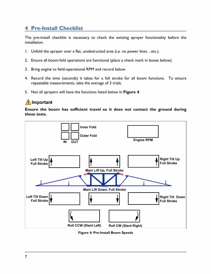
4 Pre-Install Checklist
The pre-install checklist is necessary to check the existing sprayer functionality before the installation.
1. Unfold the sprayer over a flat, unobstructed area (i.e. no power lines…etc.).
2. Ensure all boom-fold operations are functional (place a check mark in boxes below).
3. Bring engine to field-operational RPM and record below.
4. Record the time (seconds) it takes for a full stroke for all boom functions. To ensure repeatable measurements, take the average of 3 trials.
5. Not all sprayers will have the functions listed below in Figure 4.
Ensure the boom has sufficient travel so it does not contact the ground during these tests.
Figure 4: Pre-Install Boom Speeds
8
5 Ultrasonic Sensor Installation
5.1 Bracket Assembly
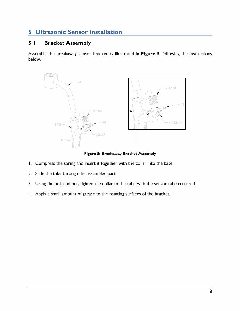
Assemble the breakaway sensor bracket as illustrated in Figure 5, following the instructions below.
Figure 5: Breakaway Bracket Assembly
1. Compress the spring and insert it together with the collar into the base.
2. Slide the tube through the assembled part.
3. Using the bolt and nut, tighten the collar to the tube with the sensor tube centered.
4. Apply a small amount of grease to the rotating surfaces of the bracket.
9
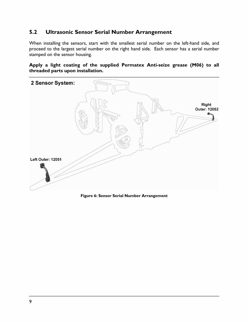
5.2 Ultrasonic Sensor Serial Number Arrangement
When installing the sensors, start with the smallest serial number on the left-hand side, and proceed to the largest serial number on the right hand side. Each sensor has a serial number stamped on the sensor housing.
Apply a light coating of the supplied Permatex Anti-seize grease (M06) to all threaded parts upon installation.
Figure 6: Sensor Serial Number Arrangement
10
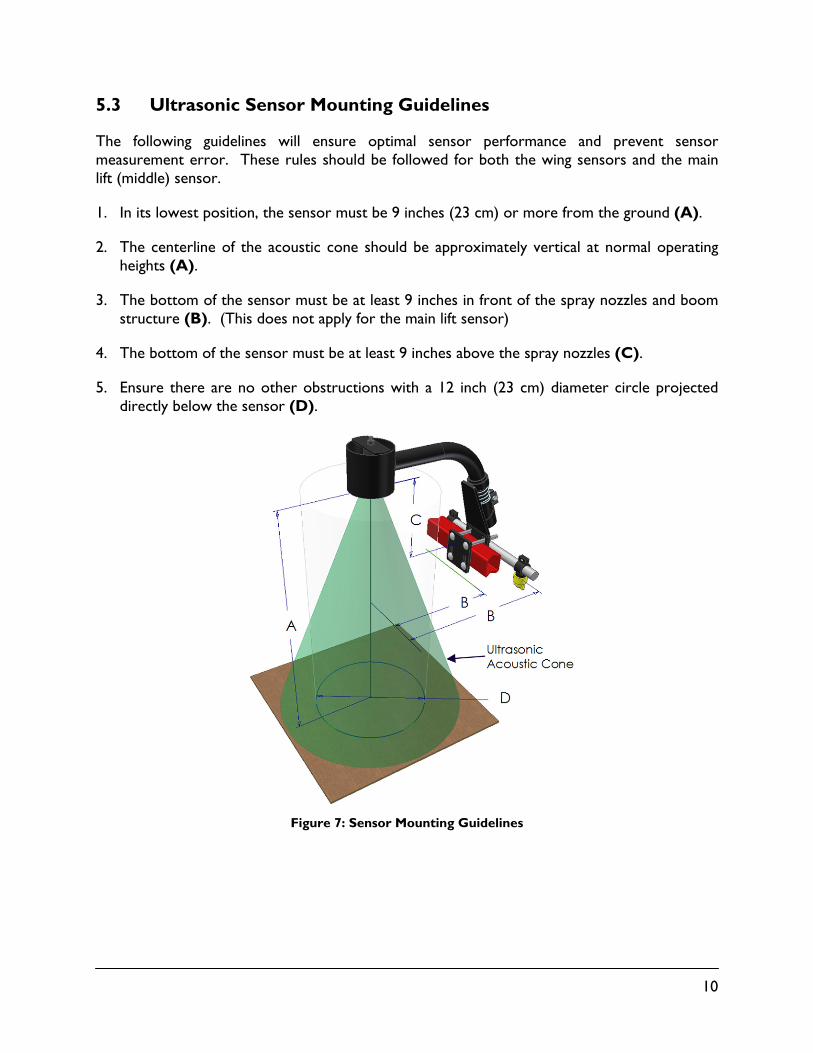
5.3 Ultrasonic Sensor Mounting Guidelines
The following guidelines will ensure optimal sensor performance and prevent sensor measurement error. These rules should be followed for both the wing sensors and the main lift (middle) sensor.
1. In its lowest position, the sensor must be 9 inches (23 cm) or more from the ground (A).
2. The centerline of the acoustic cone should be approximately vertical at normal operating heights (A).
3. The bottom of the sensor must be at least 9 inches in front of the spray nozzles and boom structure (B). (This does not apply for the main lift sensor)
4. The bottom of the sensor must be at least 9 inches above the spray nozzles (C).
5. Ensure there are no other obstructions with a 12 inch (23 cm) diameter circle projected directly below the sensor (D).
Figure 7: Sensor Mounting Guidelines
11
5.4 Wing Sensor Installation
1. The sensor bracket should be oriented forward (ahead of the boom).
2. Typically the best mounting location for the wing sensor brackets will be near the end of the boom tips, approximately two feet (60cm) from the end.
3. Depending on the boom design, some breakaway sections will lift upwards as they break back. If the sensor is mounted to this portion of the boom, the system will force the boom downwards towards the ground as the boom folds backwards.
4. Mount the NORAC ultrasonic sensor into the sensor bracket and run the sensor cable through the sensor tube.
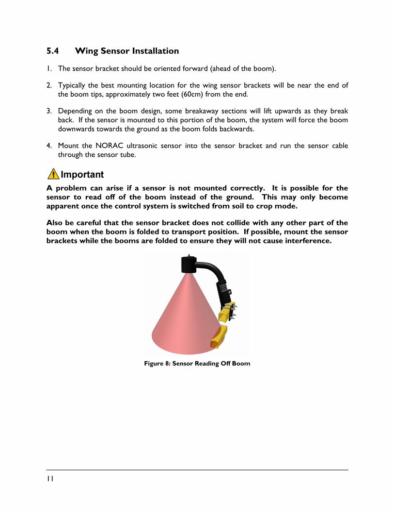
A problem can arise if a sensor is not mounted correctly. It is possible for the sensor to read off of the boom instead of the ground. This may only become apparent once the control system is switched from soil to crop mode.
Also be careful that the sensor bracket does not collide with any other part of the boom when the boom is folded to transport position. If possible, mount the sensor brackets while the booms are folded to ensure they will not cause interference.
Figure 8: Sensor Reading Off Boom
12
6 Roll Sensor Installation
6.1 Bracket Assembly
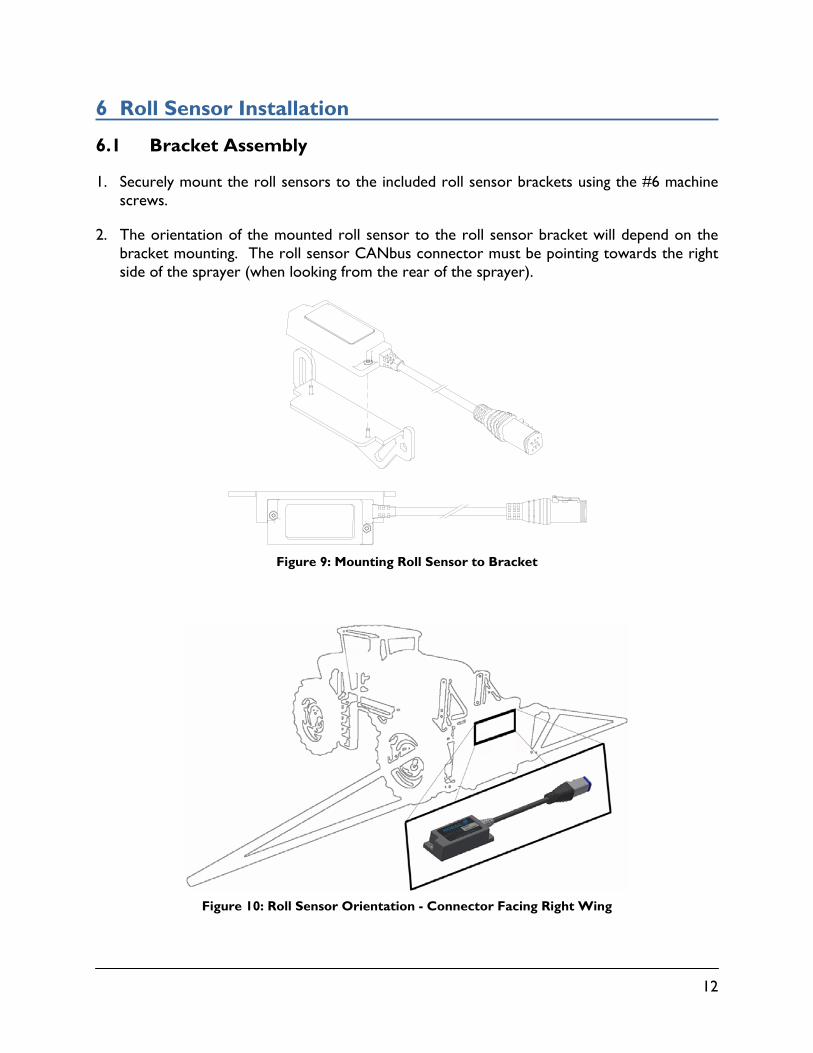
1. Securely mount the roll sensors to the included roll sensor brackets using the #6 machine screws.
2. The orientation of the mounted roll sensor to the roll sensor bracket will depend on the bracket mounting. The roll sensor CANbus connector must be pointing towards the right side of the sprayer (when looking from the rear of the sprayer).
Figure 9: Mounting Roll Sensor to Bracket
Figure 10: Roll Sensor Orientation - Connector Facing Right Wing
13
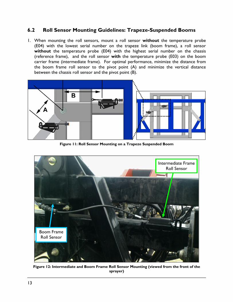
6.2 Roll Sensor Mounting Guidelines: Trapeze-Suspended Booms
1. When mounting the roll sensors, mount a roll sensor without the temperature probe (E04) with the lowest serial number on the trapeze link (boom frame), a roll sensor without the temperature probe (E04) with the highest serial number on the chassis (reference frame), and the roll sensor with the temperature probe (E03) on the boom carrier frame (intermediate frame). For optimal performance, minimize the distance from the boom frame roll sensor to the pivot point (A) and minimize the vertical distance between the chassis roll sensor and the pivot point (B).
Figure 11: Roll Sensor Mounting on a Trapeze Suspended Boom
Figure 12: Intermediate and Boom Frame Roll Sensor Mounting (viewed from the front of the
sprayer)
Boom Frame Roll Sensor
Intermediate Frame Roll Sensor
14
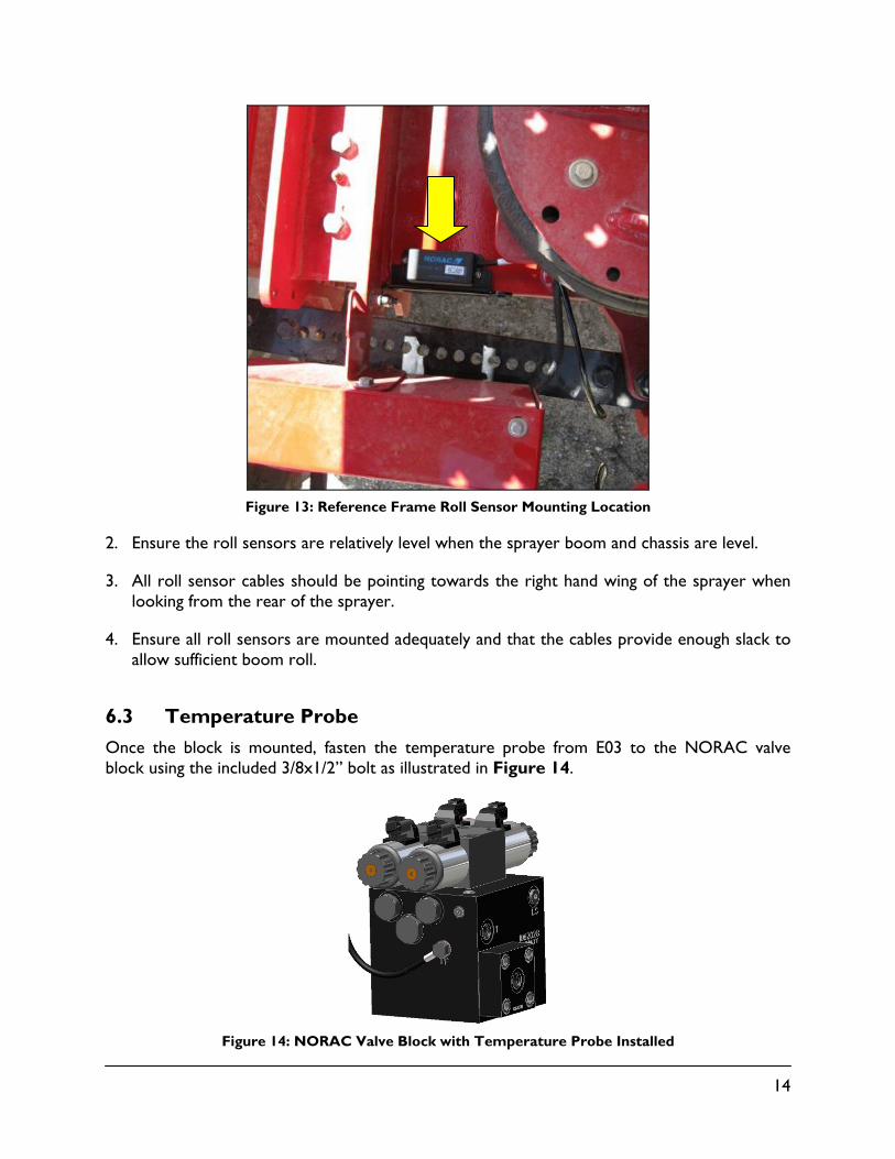
Figure 13: Reference Frame Roll Sensor Mounting Location
2. Ensure the roll sensors are relatively level when the sprayer boom and chassis are level.
3. All roll sensor cables should be pointing towards the right hand wing of the sprayer when looking from the rear of the sprayer.
4. Ensure all roll sensors are mounted adequately and that the cables provide enough slack to allow sufficient boom roll.
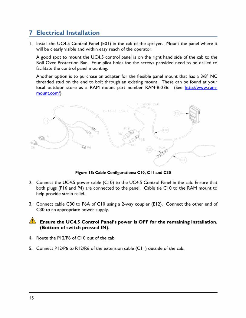
6.3 Temperature Probe
Once the block is mounted, fasten the temperature probe from E03 to the NORAC valve block using the included 3/8x1/2” bolt as illustrated in Figure 14.
Figure 14: NORAC Valve Block with Temperature Probe Installed
15
7 Electrical Installation
1. Install the UC4.5 Control Panel (E01) in the cab of the sprayer. Mount the panel where it will be clearly visible and within easy reach of the operator.
A good spot to mount the UC4.5 control panel is on the right hand side of the cab to the Roll Over Protection Bar. Four pilot holes for the screws provided need to be drilled to facilitate the control panel mounting.
Another option is to purchase an adapter for the flexible panel mount that has a 3/8" NC threaded stud on the end to bolt through an existing mount. These can be found at your local outdoor store as a RAM mount part number RAM-B-236. (See http://www.ram-mount.com/)
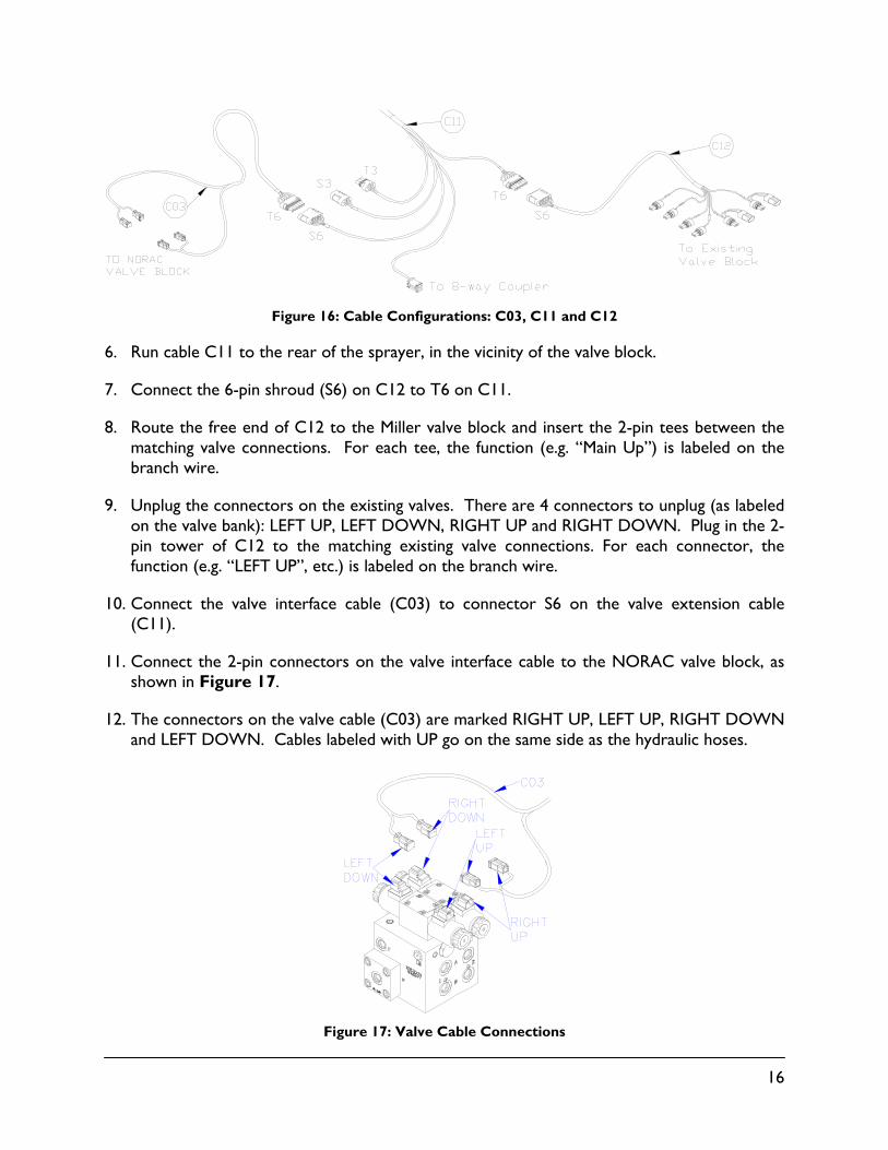
Figure 15: Cable Configurations: C10, C11 and C30
2. Connect the UC4.5 power cable (C10) to the UC4.5 Control Panel in the cab. Ensure that both plugs (P16 and P4) are connected to the panel. Cable tie C10 to the RAM mount to help provide strain relief.
3. Connect cable C30 to P6A of C10 using a 2-way coupler (E12). Connect the other end of C30 to an appropriate power supply.
Ensure the UC4.5 Control Panel’s power is OFF for the remaining installation. (Bottom of switch pressed IN).
4. Route the P12/P6 of C10 out of the cab.
5. Connect P12/P6 to R12/R6 of the extension cable (C11) outside of the cab.
16
Figure 16: Cable Configurations: C03, C11 and C12
6. Run cable C11 to the rear of the sprayer, in the vicinity of the valve block.
7. Connect the 6-pin shroud (S6) on C12 to T6 on C11.
8. Route the free end of C12 to the Miller valve block and insert the 2-pin tees between the matching valve connections. For each tee, the function (e.g. “Main Up”) is labeled on the branch wire.
9. Unplug the connectors on the existing valves. There are 4 connectors to unplug (as labeled on the valve bank): LEFT UP, LEFT DOWN, RIGHT UP and RIGHT DOWN. Plug in the 2-pin tower of C12 to the matching existing valve connections. For each connector, the function (e.g. “LEFT UP”, etc.) is labeled on the branch wire.
10. Connect the valve interface cable (C03) to connector S6 on the valve extension cable (C11).
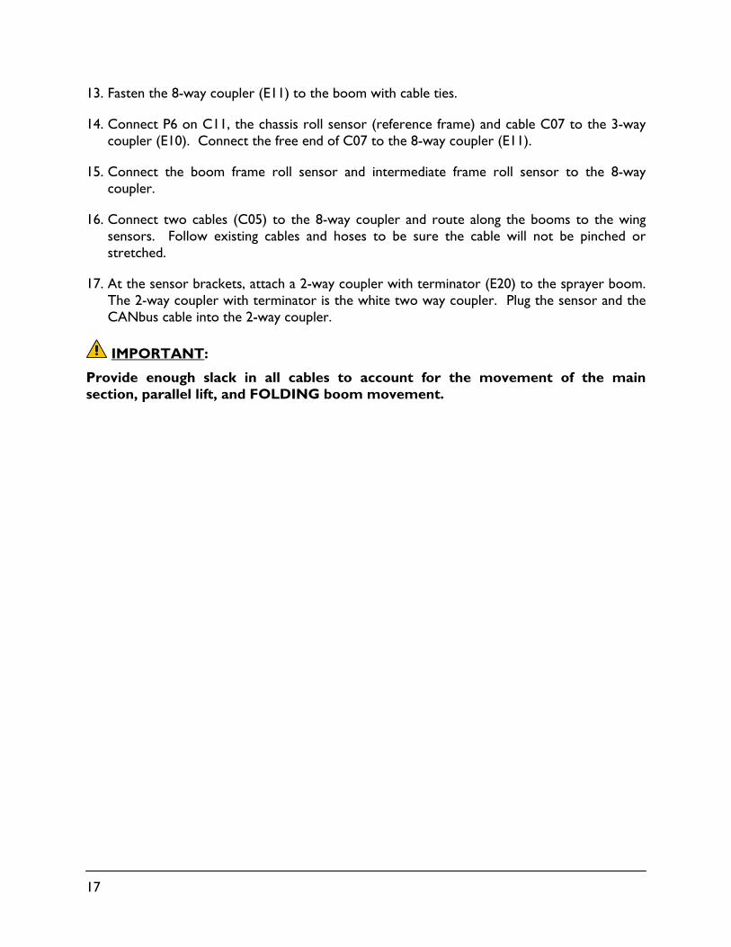
11. Connect the 2-pin connectors on the valve interface cable to the NORAC valve block, as shown in Figure 17.
12. The connectors on the valve cable (C03) are marked RIGHT UP, LEFT UP, RIGHT DOWN and LEFT DOWN. Cables labeled with UP go on the same side as the hydraulic hoses.
Figure 17: Valve Cable Connections
17
13. Fasten the 8-way coupler (E11) to the boom with cable ties.
14. Connect P6 on C11, the chassis roll sensor (reference frame) and cable C07 to the 3-way coupler (E10). Connect the free end of C07 to the 8-way coupler (E11).
15. Connect the boom frame roll sensor and intermediate frame roll sensor to the 8-way coupler.
16. Connect two cables (C05) to the 8-way coupler and route along the booms to the wing sensors. Follow existing cables and hoses to be sure the cable will not be pinched or stretched.
17. At the sensor brackets, attach a 2-way coupler with terminator (E20) to the sprayer boom. The 2-way coupler with terminator is the white two way coupler. Plug the sensor and the CANbus cable into the 2-way coupler.
IMPORTANT:
Provide enough slack in all cables to account for the movement of the main section, parallel lift, and FOLDING boom movement.
18
8 Hydraulic Installation
Ensure all pressure has been bled from the system before disconnecting any lines or fittings. Hydraulic pressure will exist on the wing tilt circuits unless the wings are being supported by other means. The hydraulic installation may be performed with the wings in transport position, resting on the ground or with the tilt cylinders fully extended.
Component failure due to oil contamination is not covered under the NORAC UC4.5 system warranty. It is recommended that a qualified technician perform the hydraulic installation.
8.1 Valve Assembly
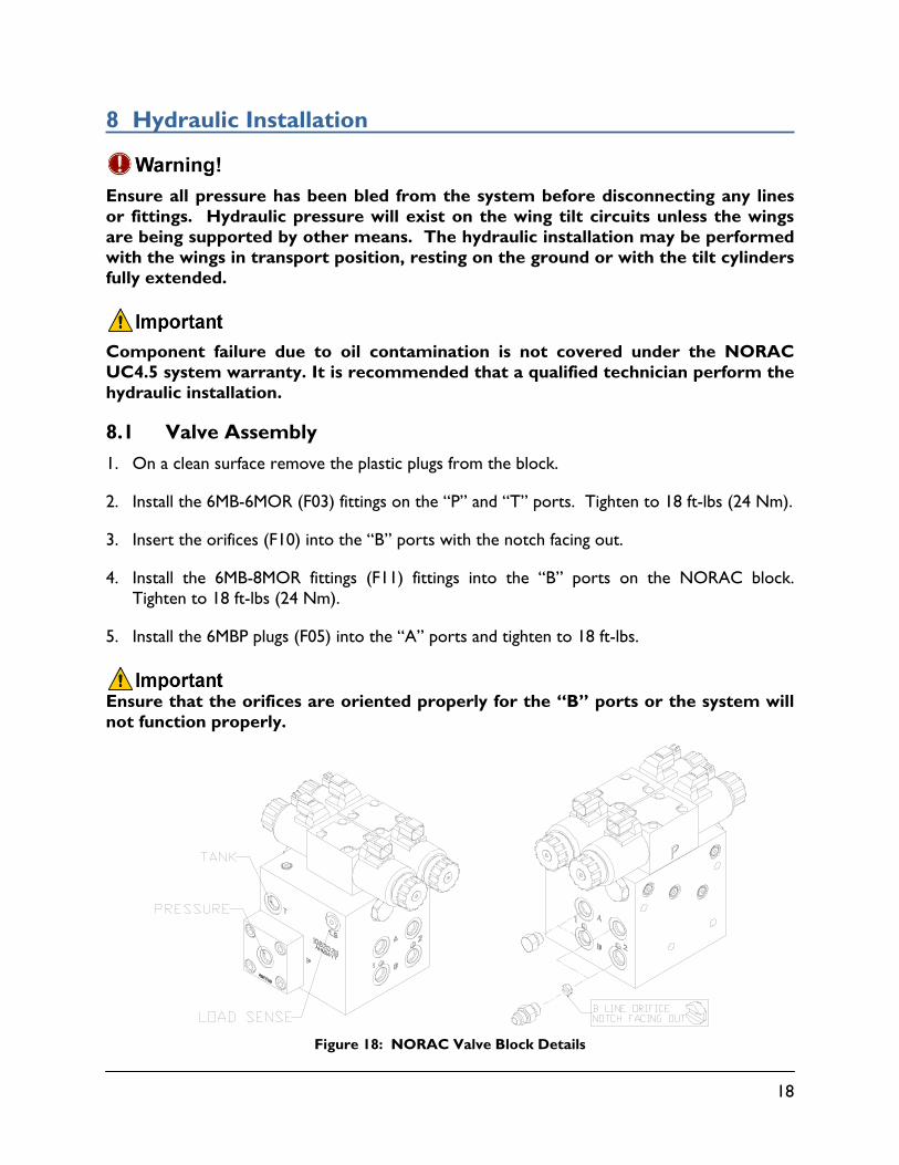
1. On a clean surface remove the plastic plugs from the block.
2. Install the 6MB-6MOR (F03) fittings on the “P” and “T” ports. Tighten to 18 ft-lbs (24 Nm).
3. Insert the orifices (F10) into the “B” ports with the notch facing out.
4. Install the 6MB-8MOR fittings (F11) fittings into the “B” ports on the NORAC block. Tighten to 18 ft-lbs (24 Nm).
5. Install the 6MBP plugs (F05) into the “A” ports and tighten to 18 ft-lbs.
Ensure that the orifices are oriented properly for the “B” ports or the system will not function properly.
Figure 18: NORAC Valve Block Details
19
8.2 Valve Block Mounting
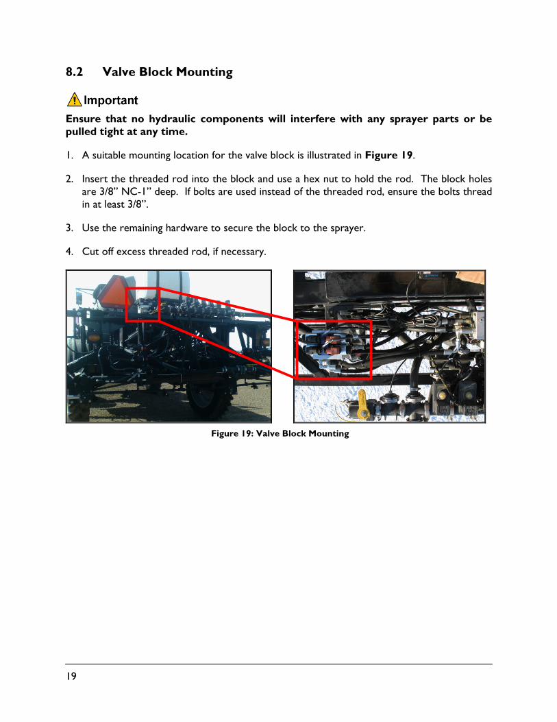
Ensure that no hydraulic components will interfere with any sprayer parts or be pulled tight at any time.
1. A suitable mounting location for the valve block is illustrated in Figure 19.
2. Insert the threaded rod into the block and use a hex nut to hold the rod. The block holes are 3/8” NC-1” deep. If bolts are used instead of the threaded rod, ensure the bolts thread in at least 3/8”.
3. Use the remaining hardware to secure the block to the sprayer.
4. Cut off excess threaded rod, if necessary.
Figure 19: Valve Block Mounting
20
8.3 Hydraulic Plumbing
From this point on in the installation the booms will be inoperative until the hydraulics are fully installed.
1. After the NORAC valves are mounted, the hydraulic hoses and fittings can be plumbed. The plumbing for the hydraulic circuit is shown schematically in Figure 3.
2. Connect the 6FORX hose end on the NORAC supplied hoses (H01) to the pressure and tank ports on the NORAC valve block using the 6MOR 6FORX90 (F02) fittings.
3. Tee the “P” line to the pressure port and the “T” line to the tank port on the sprayer valve block using the 8MB 8MOR fittings (F01).
4. Disconnect the “raise” lines from the sprayer valve block and connect them to the "B" ports of the NORAC valve block. Plug the sprayer ports with the 8MBP plugs (F12).
The following steps are only for sprayers with accumulators on the tilt cylinders.
1. Remove the 8MB 8MOR fitting from the wing accumulators.
2. Install an 8MOR 6MOR fitting (F07) into the wing accumulator.
3. Attach a 6FOR 8MOR fitting (F06) onto fitting F07 with the inline orifice (F08) between the two fittings. The inline orifice is the orifice with a groove on one side and an o-ring (F09) installed on the other side.
21
9 Software Setup
1. Start up the sprayer and test the sprayer’s functionality. The NORAC control panel does not need to be powered on for the original boom function switches to operate. Unfold the booms and raise/lower each boom and the main section.
Confirm that the cabling and hoses are agreeable to the entire range of motion.
2. If any functions do not work, review the hydraulic and electrical portions of this manual to check for proper installation.
3. Turn on the power for the UC4.5 Control Panel using the switch on the side of its chassis.
4. The procedure for the installation of the UC4.5 Spray Height Control system is now complete. Begin the AUTOMATIC SYSTEM SETUP procedure as described in the UC4.5 Spray Height Control Operator’s Manual (M01).
22
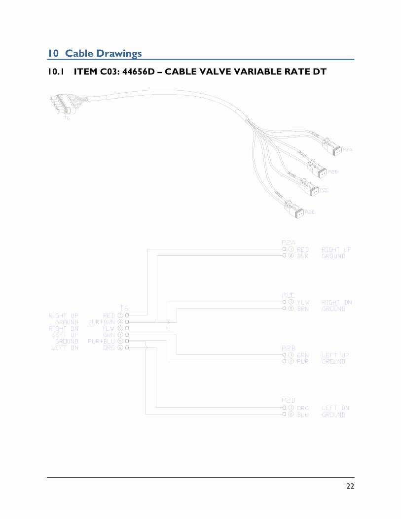
10 Cable Drawings
10.1 ITEM C03: 44656D – CABLE VALVE VARIABLE RATE DT
23
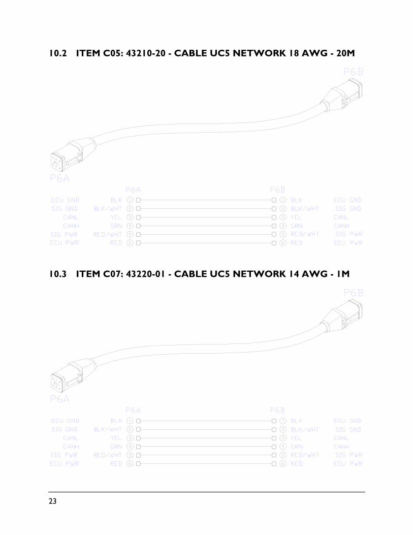
10.2 ITEM C05: 43210-20 - CABLE UC5 NETWORK 18 AWG - 20M
10.3 ITEM C07: 43220-01 - CABLE UC5 NETWORK 14 AWG - 1M
24
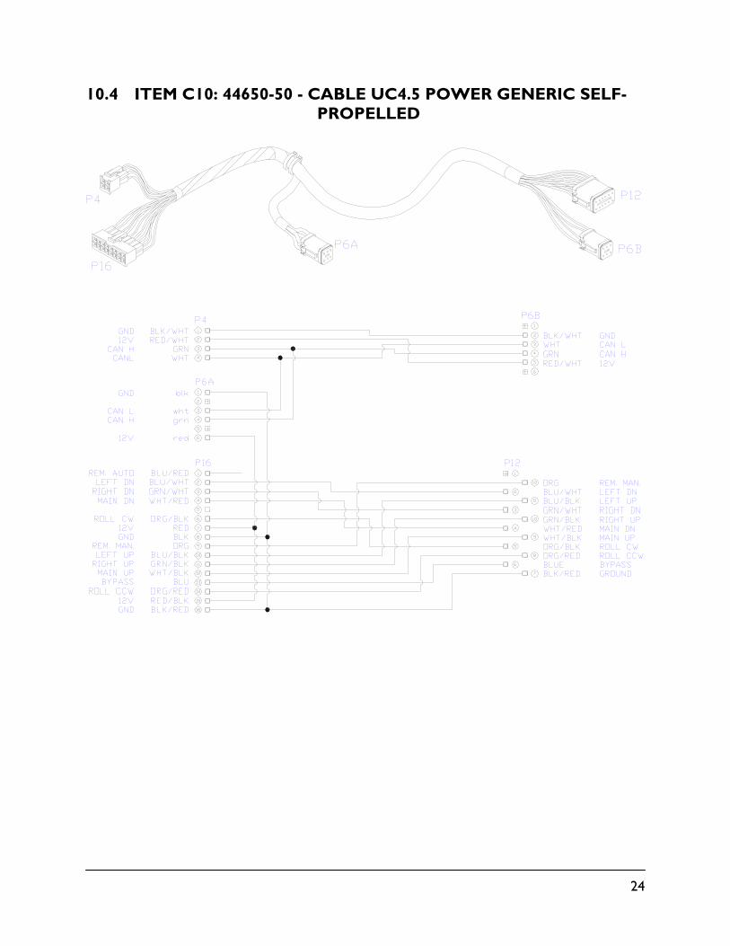
10.4 ITEM C10: 44650-50 - CABLE UC4.5 POWER GENERIC SELF-PROPELLED
25
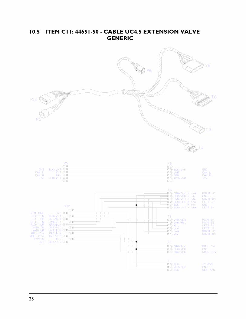
10.5 ITEM C11: 44651-50 - CABLE UC4.5 EXTENSION VALVE GENERIC
26
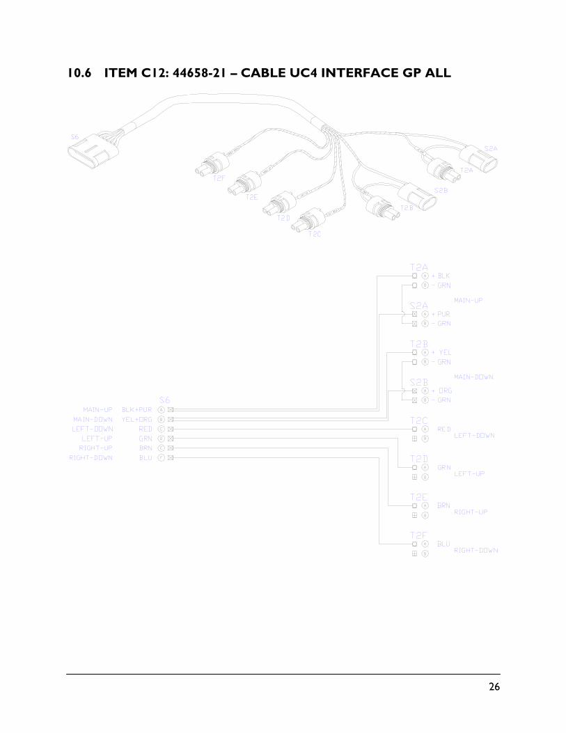
10.6 ITEM C12: 44658-21 – CABLE UC4 INTERFACE GP ALL
27
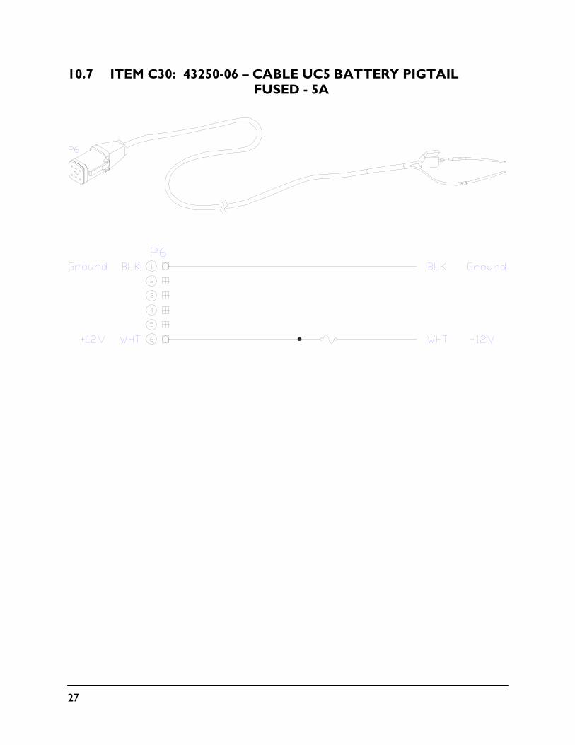
10.7 ITEM C30: 43250-06 – CABLE UC5 BATTERY PIGTAIL FUSED - 5A
Canada NORAC Systems International Inc.
Phone: (+1) 306 664 6711 Toll Free: 1 800 667 3921
Shipping Address: 3702 Kinnear Place
Saskatoon, SK S7P 0A6
United States NORAC, Inc.
Phone: (+1) 952 224 4142 Toll Free: 1 866 306 6722
Shipping Address: 6667 West Old Shakopee Road, Suite 111
Bloomington, MN 55438
Europe NORAC Europe
Phone: (+33) (0)4 26 47 04 42 Shipping Address:
Rue de l’hermitage 01090 GUEREINS
France
www.norac.ca