Embed Size (px)
Citation preview
2 Wire
4 Wire
MILLAMPERES2
4 68
10
+ HIGH
RESEARCHAMPTEC
601ES EXPLOSIVE SAFETYDIGITAL MULTIMETER
STRAY CURRENTPRESS TO MEASURE
milliammeter 0 - 10 mA DC PRESS TO MEASURE
CASEGROUND
LOW
V
I9999>>> OR
LO BATVA
.
POWER ON
OFF
STRAY CURRENT FUSE ( 5 AMPERE)
VLO
VHI
50mV - 5mA
SIGNAL SOURCE
DISPLAYBACKLIGHT
RESEARCHAMPTEC
CALIBRATED
MODEL #.
SER NO.
DATE
DUE Tamper Proof Seal/StickerCalibration void if removed
601ES
601ES-50305APR200505APR2006
I
press/hold
2.0 KOHM
20 OHM
200 OHM
2.0 OHM RE
SIS
TA
NC
E
20 KOHM
FUNCTION / RANGE
2 AMP AC/DC
600VRMS
200V AC/DC
20V AC/DC
2.0V AC/DC
AC
- D
C V
OL
TA
GE
VR
MS
Battery Compartment 4 each "AA" Alkaline
AMPTEC 601ES DMM Explosive Safety Digital Multimeter
OPERATION/MAINTENANCE MANUAL
AUSTIN, TEXAS, 78737, USA // DEFENSE LOGISTICS CAGE CODE 1CRL2 PHONE +1 (512) 858-4045 // FAX +1(512) 858-4340 EMAIL [email protected] See our website for the most up-to-date contact and product information: www.amptec.com
Revision I MAR2020
A MESSAGE FROM US
Over the past 38 years our experienced engineering staff have designed, manufactured and supplied earlier versions similar to the AMPTEC 601ES Explosive Safety DMM to the U.S. NAVY for the “TOMAHAWK CRUISE MISSILE”, the U.S. ARMY for the “STANDARD MISSILE”, the U.S.A.F. for the AIM-9 “SIDEWINDER”, AIM-7 “SPARROW” and AIM-120 “AMRAAM” just to name just a few.
Throughout this manual the AMPTEC product is referred to as the AMPTEC 601ES Explosive Safety DMM / Igniter Tester and the occasionally as "601ES DMM", in fact we are referring to the same unit . Presently, the AMPTEC 601ES Explosive Safety DMM is NASA Safety Board Approved (a copy is in the back of this manual) and it also USAF Space Systems Range Safety Approved (a copy available at www.amptec.com/tech.htm).
We value the trust our customers have placed with us, and are looking forward to supporting any new requirement you may have.
Kerry W Clark - Founder, AMPTEC RESEARCH Corp.
U.S. N.I.ST. CALIBRATION CERTIFICATE
AMPTEC RESEARCH certifies that this instrument has been completely testedand inspected and found to meet published specifications as found in this manual onthe date stated on the attached N.I.S.T. Certificate. AMPTEC RESEARCH further certifies that its calibration measurements are traceable to the U.S. National Institute of Standards and Technology.
601ES EXPLOSIVE SAFETY DMM / IGNITERTESTER WARRANTY AMPTEC RESEARCH has been proudly providing product support for all of our equipment for the past 20 years. Part of this support is offering maintenance, repair, and calibration services for our instrumentation. Our staff is highly trained across all our product lines and is capable of fixing nearly any issue your instrument may have. AMPTEC maintains one sole facility for both the manufacturing and repair of its products:
AMPTEC RESEARCH CORP.13231 Rooster Springs Rd.
Austin, TX, USA 78737
Should you have a product that you would like to be sent in for maintenance, repair, or calibration, it can be sent to the address above. Before sending in a product to our facility, you must contact a member of our staff and receive an RMA #. We can be reached via email at [email protected] or phone at +1 512-858-4045. The purpose of this process is so that we can obtain your full contact information and properly coordinate the return of the AMPTEC meter after its service. Once we have received your meter, we will diagnose the issue for free and provide you with pricing information. If diagnosing the problem requires one of our technicians to open the product in order to reach the internal circuitry, a calibration fee will be required for us to send the product back to you (unless your unit is under warranty).
R M A
1

TABLE OF CONTENTS
SECTION A: Receiving and Initial Inspection A-1 Introduction to the AMPTEC 601ES Explosive Safety DMM A-2 Receiving, Unpacking and Initial Inspection A-3 Opening the 601ES Explosive Safety DMM A-4 Battery Replacement - Power Requirements A-5 Setup and Use
SECTION B: 601ES Explosive Safety DMM Specifications B-1 Table B-1 & Specifications
SECTION C: Replacement, Optional and Accessory Items
C-1 Available Accessories and Options
SECTION D: Operation, Function and Use D-1 General D-2 Front Panel Features and Operation D-3 Complete 601ES Explosive Safety DMM Front Panel Diagram D-4 4-Wire Resistance Measurement (601ES DMM versions only) Figure D-4. Igniter Tester Kelvin Block Diagram D-5 Connections D-6 Fatigued Adapters and Loose Connections - Common Sources of Measurement Error D-7 Battery Monitoring Circuitry D-8 Failsafe Operation Overview
SECTION E: General Operation and Design E-1 General E-2 Troubleshooting E-3 Localizing the Problem E-4 Component Replacement E-5 Circuit Descriptions E-5.1 DVM IC 401 - MAX7129 E-5.2 Resistance E-5.3 Power Supply E-5.4 Relay Control E-5.5 Microprocessor E-5.6 Digital Volt Meter
2
SECTION F: Routine Maintenance F-1 General F-2 Required Test Equipment F-3 Calibration Procedure F-3.1 Zero Offset Adjustment F-3.2 Full Scale Adjustment F-3.3 2.0 Ohm Range Adjustments F-3.4 Verification of Each Ranges Accuracy F-3.5 AC/DC Voltage Adjustments F-3.6 AC/DC Current Adjustments F-3.7 50mV/5mA Signal Source Adjustments F-4 Battery Replacement Instructions
X
3

A-1. Introduction to the AMPTEC 601ES Explosive Safety DMM / Igniter Tester
The AMPTEC 620A, 630 , 640 series and now the AMPTEC 601 Series Explosive Safety DMMs are designed to be the "Standard in the Explosive Safety Igniter Circuit Test industry", and provide extremely safe and reliable voltage , current and resistance measurement/testing of explosive or volatile devices. Safety Approvals from various Safety Boards include, the U.S. Air Force ( 620A-4) for generic use on missile warheads and the US NAVAL ORDNANCE CENTER (630AN, 630BN, 640N and other versions pending). Some of the devices the 601ES DMM Explosive Safety Meter may be used on include: fuses, squibs, igniters, EBW, explosive bolts, rocket motor squibs, to name a few.
The AMPTEC 601ES Explosive Safety DMM supports safe ordnance testing. Many customers need to safely measure stray voltage circuitry ( RMS AC and DC), stray current and resistance using the failsafe output circuitry proprietary to AMPTEC RESEARCH insure that test current levels coming from the 601ES don’t exceed the specified "failsafe current" even in a worst-case component failure situation. The failsafe feature is tested in every instrument before shipment. A built-in passive (analog) DC Milliammeter also lets the user verify actual 601ES DMM current output levels prior to connection to any EBW, squib or detonator.
Power On - The AMPTEC 601ES DMM Explosive Safety Meter main "Power" switch must be held down for 2 seconds to turn the meter "ON" or "OFF". This feature helps prevent the unwanted effect of bumping of the power switch and accidentally turning the meter "OFF" or "ON".
Low or Dead batteries ( AA type Alkaline - 4 each ) is the primary reason for the AMPTEC 601ES DMM not powering up. If the batteries reach a low energy level the unit's LCD Display "LO BAT" indicator appears on the display.
The AMPTEC 601ES DMM SafetyMeter has a battery monitoringcircuit that indicates when it is timeTo replace the batteries. They can be replaced without effecting the calibration of the meter. The batteries are housed in their own compartment completely separate from any active electronic circuitry.
A-2. Receiving, Unpacking, and Initial Inspection
Should the AMPTEC shipping box appear damaged upon arrival, request that the carrier's agent (i.e. UPS) be present when the unit is unpacked. If the 601ES DMM Explosive Safety Meter appears damaged, the carrier's agent should authorize repairs before the unit is returned to the factory. Even if the instrument appears undamaged, it may have suffered internal damage in transit that may not be evident until the unit is operated or tested to verify conformance with its specifications. You may refer to the Trouble-Shooting section of Chapter D of this manual to help identify the problem (i.e Test leads etc.)
If the unit fails to operate or fails tomeet the performance specificationsof section B, notify the carrier'sagent and AMPTEC RESEARCH . Retain the shipping carton for thecarrier's inspection. DO NOT return equipment to AMPTEC RESEARCH or any of its sales offices without first obtaining an (RMA) Return Material Authorization number. We need to know who to contact and how to contact (i.e. phone number and FAX number) in order to properly coordinate the return of the repaired AMPTEC product. By calling AMPTEC RESEARCH first, prior to just returning the 601ES DMM Explosive Safety Meter, we can often trouble-shoot (based on the symptoms you describe) and identify the problem over the phone (i.e battery loose in the battery holder). We may possibly be able to fix the problem over the phone and prevent you from having to return the unit to AMPTEC for repair.
SECTION A - RECEIVING AND INITIAL INSPECTION
R M A
4
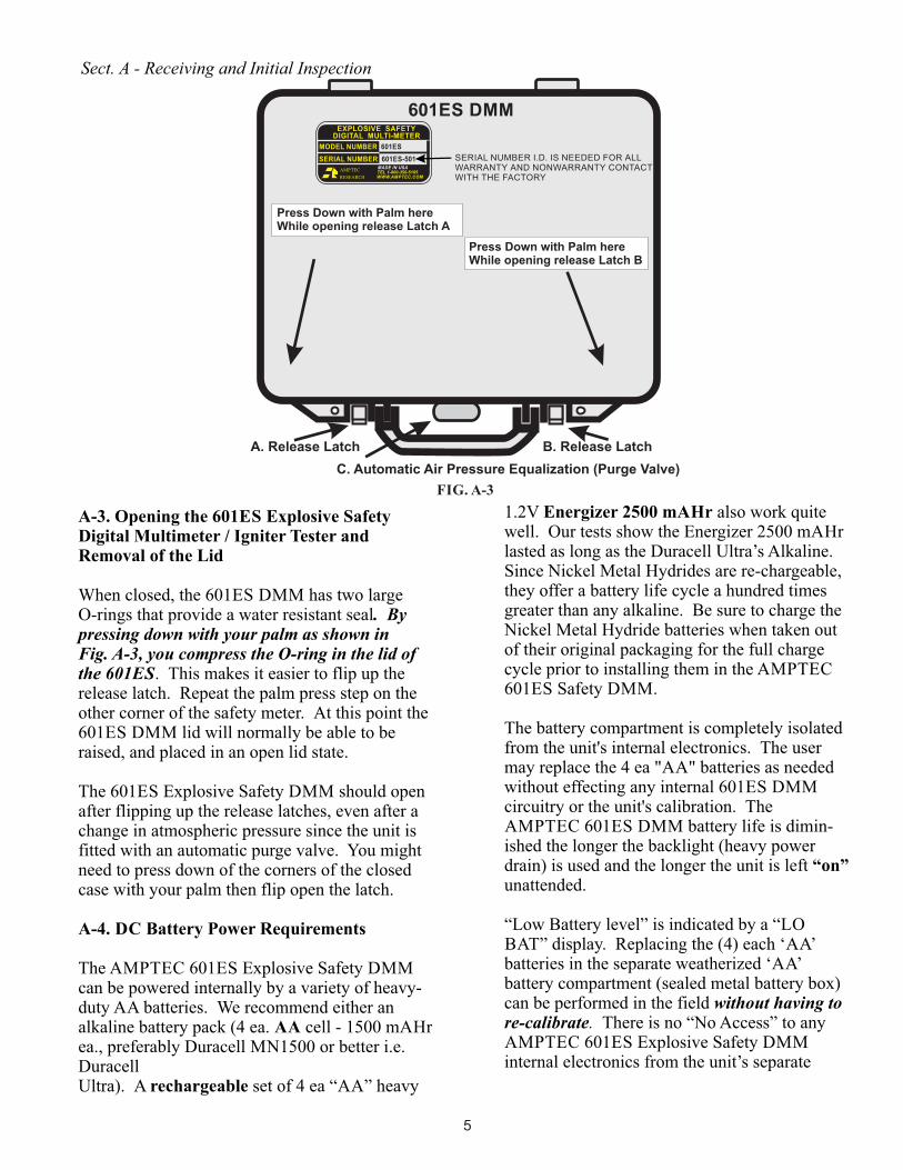
A-3. Opening the 601ES Explosive Safety Digital Multimeter / Igniter Tester and Removal of the Lid
When closed, the 601ES DMM has two largeO-rings that provide a water resistant seal. By pressing down with your palm as shown inFig. A-3, you compress the O-ring in the lid of the 601ES. This makes it easier to flip up the release latch. Repeat the palm press step on the other corner of the safety meter. At this point the 601ES DMM lid will normally be able to be raised, and placed in an open lid state. The 601ES Explosive Safety DMM should open after flipping up the release latches, even after a change in atmospheric pressure since the unit is fitted with an automatic purge valve. You might need to press down of the corners of the closed case with your palm then flip open the latch.
A-4. DC Battery Power Requirements
The AMPTEC 601ES Explosive Safety DMM can be powered internally by a variety of heavy-duty AA batteries. We recommend either an alkaline battery pack (4 ea. AA cell - 1500 mAHr ea., preferably Duracell MN1500 or better i.e. Duracell Ultra). A rechargeable set of 4 ea “AA” heavy
1.2V Energizer 2500 mAHr also work quite well. Our tests show the Energizer 2500 mAHr lasted as long as the Duracell Ultra’s Alkaline. Since Nickel Metal Hydrides are re-chargeable, they offer a battery life cycle a hundred times greater than any alkaline. Be sure to charge the Nickel Metal Hydride batteries when taken out of their original packaging for the full charge cycle prior to installing them in the AMPTEC 601ES Safety DMM.
The battery compartment is completely isolated from the unit's internal electronics. The user may replace the 4 ea "AA" batteries as needed without effecting any internal 601ES DMM circuitry or the unit's calibration. The AMPTEC 601ES DMM battery life is dimin-ished the longer the backlight (heavy power drain) is used and the longer the unit is left “on” unattended.
“Low Battery level” is indicated by a “LO BAT” display. Replacing the (4) each ‘AA’ batteries in the separate weatherized ‘AA’ battery compartment (sealed metal battery box) can be performed in the field without having to re-calibrate. There is no “No Access” to any AMPTEC 601ES Explosive Safety DMM internal electronics from the unit’s separate
601ES DMM
Press Down with Palm hereWhile opening release Latch A
Press Down with Palm hereWhile opening release Latch B
A. Release Latch B. Release Latch
C. Automatic Air Pressure Equalization (Purge Valve)
Sect. A - Receiving and Initial Inspection
FIG. A-3
MADE IN USA
WWW.AMPTEC.COMTEL 1-800-350-5105
RESEARCHAMPTEC
EXPLOSIVE SAFETY DIGITAL MULTI-METER
MODEL NUMBER 601ES
SERIAL NUMBER 601ES-501
5
SERIAL NUMBER I.D. IS NEEDED FOR ALLWARRANTY AND NONWARRANTY CONTACTWITH THE FACTORY
Avoid exposing the 601ES Explosive Safety DMM to extremes of temperature which will affect accuracy and shorten battery pack lifespan.
Once the 601ES DMM main power switch is turned "ON" and following a (1) minute warmup, (provided there is No ‘LO BAT’ Indicator shown) the AMPTEC 601ES Explosive Safety DMM should be ready for general purpose testing and use.
The 601ES DMM operator may be asked to perform a series of tests (i.e. verify the test current is less than 10mA with the unit's DC milliammeter) prior to connection to any explosive device under test.
Test lead sets may also be placed in the pouch which holds the laminated AMPTEC 601ES DMM Operator Instruction Card.
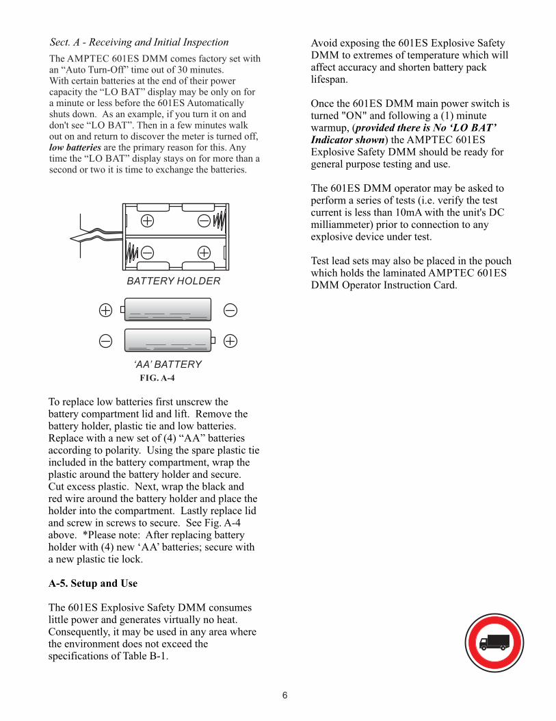
To replace low batteries first unscrew the battery compartment lid and lift. Remove the battery holder, plastic tie and low batteries.Replace with a new set of (4) “AA” batteries according to polarity. Using the spare plastic tie included in the battery compartment, wrap the plastic around the battery holder and secure. Cut excess plastic. Next, wrap the black and red wire around the battery holder and place the holder into the compartment. Lastly replace lid and screw in screws to secure. See Fig. A-4 above. *Please note: After replacing battery holder with (4) new ‘AA’ batteries; secure with a new plastic tie lock.
A-5. Setup and Use The 601ES Explosive Safety DMM consumes little power and generates virtually no heat. Consequently, it may be used in any area where the environment does not exceed the specifications of Table B-1.
BATTERY HOLDER
‘AA’ BATTERY
FIG. A-4
Sect. A - Receiving and Initial Inspection
The AMPTEC 601ES DMM comes factory set with an “Auto Turn-Off” time out of 30 minutes. With certain batteries at the end of their power capacity the “LO BAT” display may be only on for a minute or less before the 601ES Automatically shuts down. As an example, if you turn it on and don't see “LO BAT”. Then in a few minutes walk out on and return to discover the meter is turned off, low batteries are the primary reason for this. Any time the “LO BAT” display stays on for more than a second or two it is time to exchange the batteries.
6
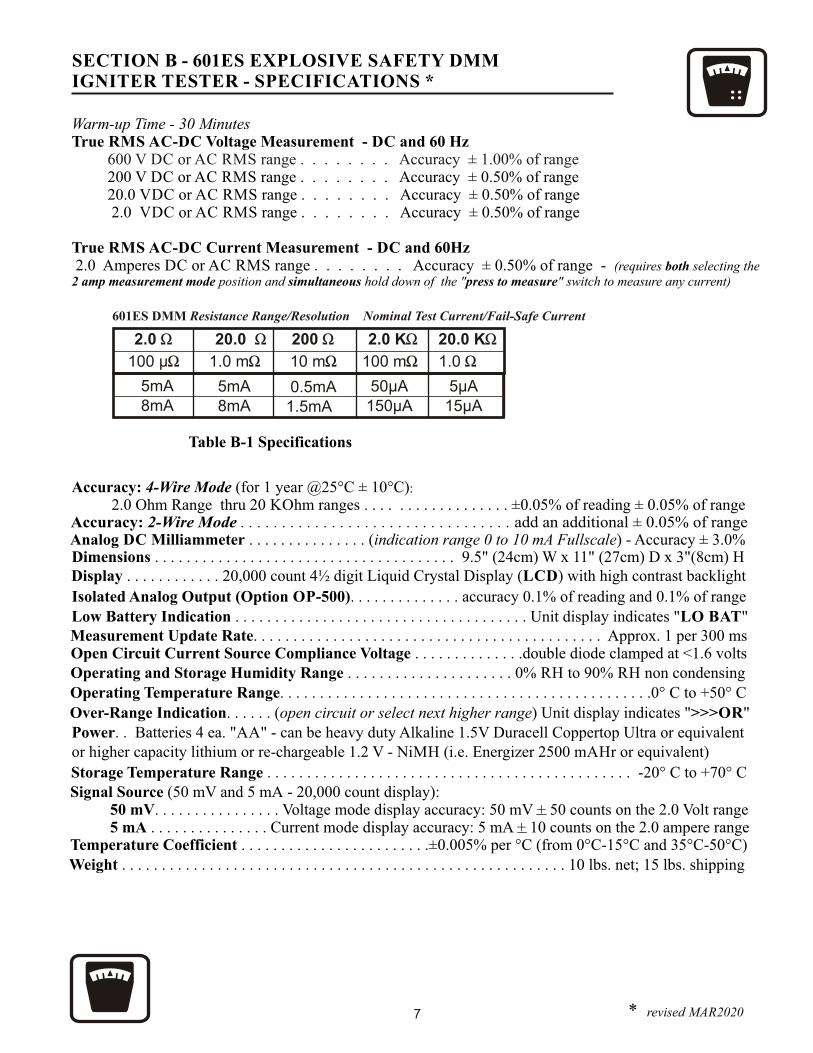
SECTION B - 601ES EXPLOSIVE SAFETY DMMIGNITER TESTER - SPECIFICATIONS *
Warm-up Time - 30 Minutes True RMS AC-DC Voltage Measurement - DC and 60 Hz 200 V DC or AC RMS range . . . . . . . . Accuracy ± 0.50% of range 20.0 VDC or AC RMS range . . . . . . . . Accuracy ± 0.50% of range 2.0 VDC or AC RMS range . . . . . . . . Accuracy ± 0.50% of range
True RMS AC-DC Current Measurement - DC and 60Hz 2.0 Amperes DC or AC RMS range . . . . . . . . Accuracy ± 0.50% of range - (requires both selecting the 2 amp measurement mode position and simultaneous hold down of the "press to measure" switch to measure any current)
Table B-1 Specifications
Accuracy: 4-Wire Mode (for 1 year @25°C ± 10°C) 2.0 Ohm Range thru 20 KOhm ranges . . . . . . . . . . . . . . . . . . ±0.05% of reading ± 0.05% of range
Accuracy: 2-Wire Mode . . . . . . . . . . . . . . . . . . . . . . . . . . . . . . . . . add an additional ± 0.05% of range
Signal Source (50 mV and 5 mA - 20,000 count display): 50 mV. . . . . . . . . . . . . . . . Voltage mode display accuracy: 50 mV + 50 counts on the 2.0 Volt range 5 mA . . . . . . . . . . . . . . . Current mode display accuracy: 5 mA + 10 counts on the 2.0 ampere rangeTemperature Coefficient . . . . . . . . . . . . . . . . . . . . . . . .±0.005% per °C (from 0°C-15°C and 35°C-50°C)
Display . . . . . . . . . . . . 20,000 count 4½ digit Liquid Crystal Display (LCD) with high contrast backlight
Low Battery Indication . . . . . . . . . . . . . . . . . . . . . . . . . . . . . . . . . . . . . Unit display indicates "LO BAT"
Over-Range Indication. . . . . . (open circuit or select next higher range) Unit display indicates ">>>OR"
Measurement Update Rate. . . . . . . . . . . . . . . . . . . . . . . . . . . . . . . . . . . . . . . . . . . . Approx. 1 per 300 ms
Analog DC Milliammeter . . . . . . . . . . . . . . . (indication range 0 to 10 mA Fullscale) - Accuracy ± 3.0%
Open Circuit Current Source Compliance Voltage . . . . . . . . . . . . . .double diode clamped at <1.6 volts
Power. . Batteries 4 ea. "AA" - can be heavy duty Alkaline 1.5V Duracell Coppertop Ultra or equivalent or higher capacity lithium or re-chargeable 1.2 V - NiMH (i.e. Energizer 2500 mAHr or equivalent)
Dimensions . . . . . . . . . . . . . . . . . . . . . . . . . . . . . . . . . . . . . . 9.5" (24cm) W x 11" (27cm) D x 3"(8cm) H
Isolated Analog Output (Option OP-500). . . . . . . . . . . . . . accuracy 0.1% of reading and 0.1% of range
* revised MAR2020
600 V DC or AC RMS range . . . . . . . . Accuracy ± 1.00% of range
7
Operating Temperature Range. . . . . . . . . . . . . . . . . . . . . . . . . . . . . . . . . . . . . . . . . . . . . . .0° C to +50° COperating and Storage Humidity Range . . . . . . . . . . . . . . . . . . . . . 0% RH to 90% RH non condensing
Storage Temperature Range . . . . . . . . . . . . . . . . . . . . . . . . . . . . . . . . . . . . . . . . . . . . . . -20° C to +70° C
:
Weight . . . . . . . . . . . . . . . . . . . . . . . . . . . . . . . . . . . . . . . . . . . . . . . . . . . . . . . . 10 lbs. net; 15 lbs. shipping
C-1. Available Accessories and Options
This manual does not list all possible accessories that AMPTEC RESEARCH is willing to provide as a support items for the AMPTEC 601ES DMM. Contact the sales department at AMPTEC RESEARCH if you have a request for an item that is not described here. Listed below are some of the options available for use with the AMPTEC 601ES Explosive Safety DMM.
Kelvin Leads, Probes Accessories and Options
All AMPTEC series test lead and probe sets are a minimum 48" length, dual banana termination at the ohmmeter end (call the Sales Department at AMPTEC RESEARCH for any custom requirement).
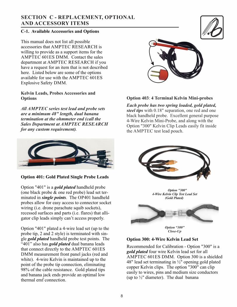
Option 401: Gold Plated Single Probe Leads
Option "401" is a gold plated handheld probe (one black probe & one red probe) lead set ter-minated in single points. The OP401 handheld probes allow for easy access to connector socket wiring (i.e. drone parachute squib sockets), recessed surfaces and parts (i.e. flares) that alli-gator clip leads simply can’t access properly.
Option "401" plated a 4-wire lead set (up to the probe tip, 2 and 2 style) is terminated with sin-gle gold plated handheld probe test points. The “401” also has gold plated dual banana leads that connect directly to the AMPTEC 601ES DMM measurement front panel jacks (red and white). 4-wire Kelvin is maintained up to the point of the probe tip connection, eliminating 98% of the cable resistance. Gold plated tips and banana jack ends provide an optimal low thermal emf connection.
Option 403: 4 Terminal Kelvin Mini-probes
Each probe has two spring loaded, gold plated, steel tips with 0.18" separation, one red and one black handheld probe. Excellent general purpose 4-Wire Kelvin Mini-Probe, and along with the Option "300" Kelvin Clip Leads easily fit inside the AMPTEC test lead pouch.
Option 300: 4-Wire Kelvin Lead Set
Recommended for Calibration - Option "300" is a gold plated four wire Kelvin lead set for all AMPTEC 601ES DMM. Option 300 is a shielded 48" lead set terminating in ½" opening gold plated copper Kelvin clips. The option "300" can clip easily to wires, pins and medium size conductors (up to ½" diameter). The dual banana
Option “300”Close-Up
Option "300" 4-Wire Kelvin Clip Test Lead Set
(Gold Plated)
SECTION C - REPLACEMENT, OPTIONALAND ACCESSORY ITEMS
8
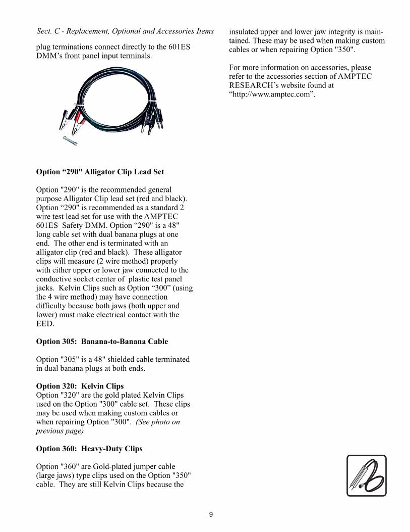
plug terminations connect directly to the 601ES DMM’s front panel input terminals.
Option “290" Alligator Clip Lead Set
Option "290" is the recommended general purpose Alligator Clip lead set (red and black). Option “290" is recommended as a standard 2 wire test lead set for use with the AMPTEC 601ES Safety DMM. Option “290" is a 48" long cable set with dual banana plugs at one end. The other end is terminated with an alligator clip (red and black). These alligator clips will measure (2 wire method) properly with either upper or lower jaw connected to the conductive socket center of plastic test panel jacks. Kelvin Clips such as Option “300” (using the 4 wire method) may have connection difficulty because both jaws (both upper and lower) must make electrical contact with the EED.
Option 305: Banana-to-Banana Cable
Option "305" is a 48" shielded cable terminated in dual banana plugs at both ends.
Option 320: Kelvin ClipsOption "320" are the gold plated Kelvin Clips used on the Option "300" cable set. These clips may be used when making custom cables or when repairing Option "300". (See photo on previous page)
Option 360: Heavy-Duty Clips
Option "360" are Gold-plated jumper cable (large jaws) type clips used on the Option "350" cable. They are still Kelvin Clips because the
insulated upper and lower jaw integrity is main-tained. These may be used when making custom cables or when repairing Option "350".
For more information on accessories, please refer to the accessories section of AMPTEC RESEARCH’s website found at “http://www.amptec.com”.
Sect. C - Replacement, Optional and Accessories Items
9
D-1. General Operation
A diagram and description of the front panel controls, connection instructions, and the theory behind resistance measurement is discussed in this section. This section of the manual contains complete operating instructions for the AMPTEC 601ES Explosive Safety DMM.
D-2. Front Panel Features and Operation
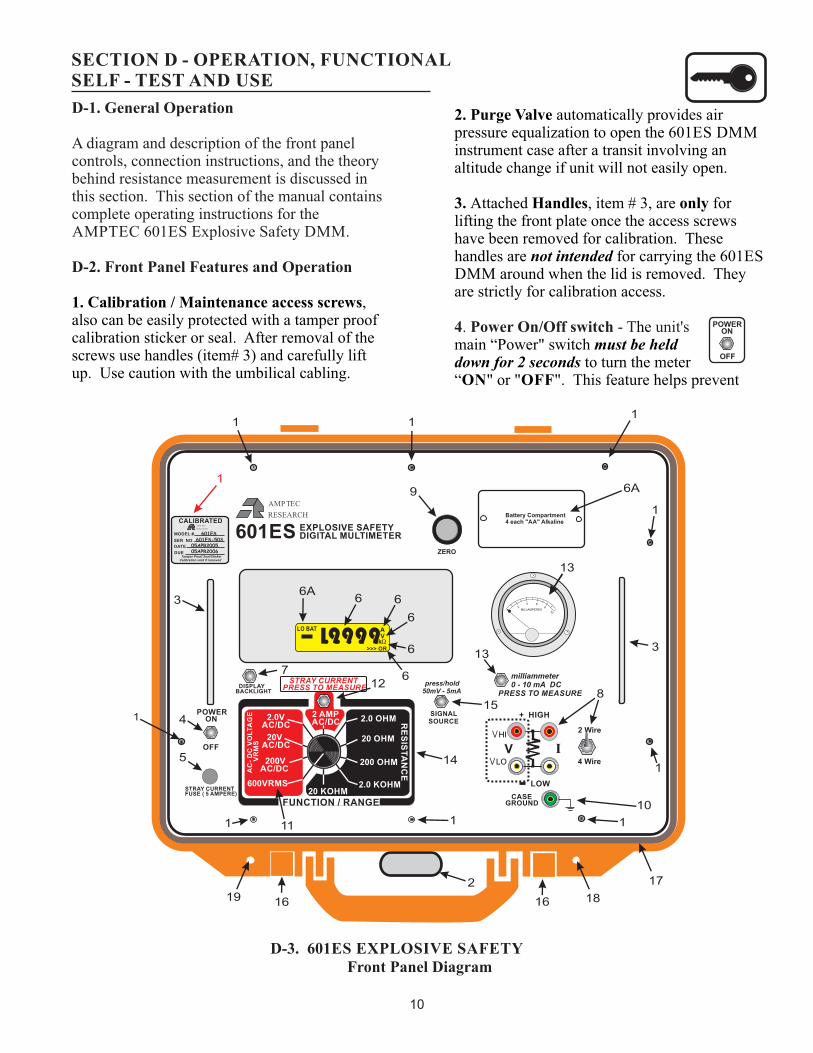
1. Calibration / Maintenance access screws, also can be easily protected with a tamper proof calibration sticker or seal. After removal of the screws use handles (item# 3) and carefully lift up. Use caution with the umbilical cabling.
SECTION D - OPERATION, FUNCTIONAL SELF - TEST AND USE
2. Purge Valve automatically provides air pressure equalization to open the 601ES DMM instrument case after a transit involving an altitude change if unit will not easily open.
3. Attached Handles, item # 3, are only for lifting the front plate once the access screws have been removed for calibration. These handles are not intended for carrying the 601ES DMM around when the lid is removed. They are strictly for calibration access.
4. Power On/Off switch - T unit's hemain “Power" switch must be helddown for 2 seconds to turn the meter“ON" or "OFF". This feature helps prevent
Front Panel DiagramD-3. 601ES EXPLOSIVE SAFETY
2 Wire
4 Wire
MILLAMPERES2
4 68
10
+ HIGH
RESEARCHAMPTEC
601ES EXPLOSIVE SAFETYDIGITAL MULTIMETER
STRAY CURRENTPRESS TO MEASURE
milliammeter 0 - 10 mA DC PRESS TO MEASURE
CASEGROUND
2.0 KOHM
20 OHM
200 OHM
2.0 OHM RE
SIS
TA
NC
E
20 KOHM LOW
V
I9999>>> OR
LO BATVA
. . . .
11
1
8
9
1
14
11
17
12
POWER ON
OFF
STRAY CURRENT FUSE ( 5 AMPERE)
1
4
5
3
2
15
1616
13
13
6A
6A
7
1
1
3
1
10
VLO
VHI
50mV - 5mA
SIGNAL SOURCE
DISPLAYBACKLIGHT
1
RESEARCHAMPTEC
CALIBRATED
MODEL #.
SER NO.
DATE
DUE Tamper Proof Seal/StickerCalibration void if removed
601ES
601ES-50305APR200505APR2006
I
FUNCTION / RANGE
2 AMP AC/DC
600VRMS
200V AC/DC
20V AC/DC
2.0V AC/DC
AC
- D
C V
OL
TA
GE
VR
MS
press/hold
Battery Compartment 4 each "AA" Alkaline
1819
6 6
6
6
6
1
10

6A. The LCD Display will indicate "LO BAT" when it is time to replace the batteries. It will typically come on when the AMPTEC 601ES DMM internal batteries (4 ea. 1.5VDC alkalines - Duracell Mn1500 or better) reach approx. 3.6 VDC. To change the batteries remove the screws securing the battery compartment. The back side of the battery compartment cover is lined with a sponge fill neoprene gasket to help provide a water resistant battery compartment.Carefully pull the battery holder out and remove the cable-tie securing the batteries. Observe battery polarity when replacing the "AA" batter-ies. Re-secure the four new batteries in the holder with a new cable tie, then return it to the battery compartment and re-secure the compart-ment lid (screws). See section A-4 for diagram.
7. Display Backlight is activated when the push button is held down. Display is back-lit with a yellow green hue. This process aids in the visi-bility of the digits when exterior lighting is dim. Please note the use of this feature should be used sparingly in order to conserve battery reserves.
inadvertent power loss (i.e. bumping of the power switch and accidentally turning the meter "OFF"). Automatic Turn-Off : The AMPTEC 601ES Explosive Safety DMM is factory set, using internal PCB jumpers, to automatically turn-off after (30) minutes of inactivity (no range or function change) to conserve battery power.
5. Protection Fuse (5.0 amp fast blow type) protects the 2.0 ampere Stray Current Range (measurement). The type of fuse used is a Little fuse 3AG or equivalent.
6. The LCD Display is 20,000 count (1 and four 9’s), 4 ½ digit design. LCD display annunciators includes A (Amperes), V (Volt annunciator), Mk (Megakilo Ohms) and the >>> OR (Over Range). Unused LCD display annunciators include "SELF-TEST" and "OK" which will be available for future capabilities with AMPTEC RESEARCH safety meters.
MILLAMPERES2
4 68
10
+ HIGH
RESEARCHAMPTEC
601ES EXPLOSIVE SAFETYDIGITAL MULTIMETER
STRAY CURRENTPRESS TO MEASURE
milliammeter 0 - 10 mA DC PRESS TO MEASURE
CASEGROUND
2.0 KOHM
20 OHM
200 OHM
2.0 OHM RE
SIS
TA
NC
E
20 KOHM LOW
V
I9999>>> OR
LO BATVA
. . . .
1 1
1
8
9
1
14
11
12
POWER ON
OFF
STRAY CURRENT FUSE ( 5 AMPERE)
1
4
13
13
3
2
15
1616
5
6A
6A
7
1
1
3
2 Wire
4 Wire
8
1
10
VLO
VHI
50mV - 5mA
SIGNAL SOURCE
DISPLAYBACKLIGHT
1
RESEARCHAMPTEC
CALIBRATED
MODEL #.
SER NO.
DATE
DUE Tamper Proof Seal/StickerCalibration void if removed
601ES
601ES-50305APR200505APR2006
I
FUNCTION / RANGE
2 AMP AC/DC
600VRMS
200V AC/DC
20V AC/DC
2.0V AC/DC
AC
- D
C V
OL
TA
GE
V
RM
S
press/hold
Battery Compartment 4 each "AA" Alkaline
18
17
19
1
6 6
6
6
6
601ES EXPLOSIVE SAFETY DMMFIG. D-3
Sect. D - Operation, Functional Self-Test and Use
11
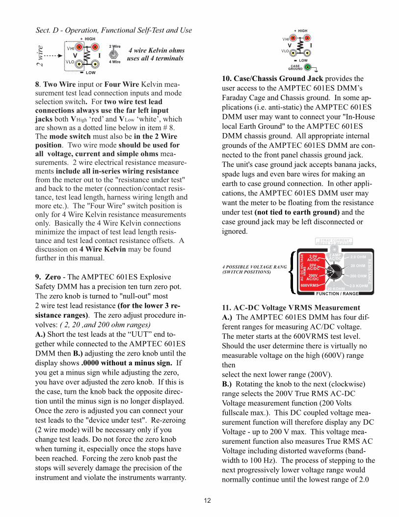
8. Two Wire input or Four Wire Kelvin mea-surement test lead connection inputs and mode selection switch. For two wire test lead connections always use the far left input jacks both VHigh ‘red’ and VLow ‘white’, which are shown as a dotted line below in item # 8. The mode switch must also be in the 2 Wire position. Two wire mode should be used for all voltage, current and simple ohms mea-surements. 2 wire electrical resistance measure-ments include all in-series wiring resistance from the meter out to the "resistance under test" and back to the meter (connection/contact resis-tance, test lead length, harness wiring length and more etc.). The "Four Wire" switch position is only for 4 Wire Kelvin resistance measurements only. Basically the 4 Wire Kelvin connections minimize the impact of test lead length resis-tance and test lead contact resistance offsets. A discussion on 4 Wire Kelvin may be foundfurther in this manual.
9. Zero - The AMPTEC 601ES Explosive Safety DMM has a precision ten turn zero pot. The zero knob is turned to "null-out" most 2 wire test lead resistance (for the lower 3 re-sistance ranges). The zero adjust procedure in-volves: ( 2, 20 ,and 200 ohm ranges)A.) Short the test leads at the “UUT” end to-gether while connected to the AMPTEC 601ES DMM then B.) adjusting the zero knob until the display shows .0000 without a minus sign. If you get a minus sign while adjusting the zero, you have over adjusted the zero knob. If this is the case, turn the knob back the opposite direc-tion until the minus sign is no longer displayed. Once the zero is adjusted you can connect your test leads to the "device under test". Re-zeroing (2 wire mode) will be necessary only if you change test leads. Do not force the zero knob when turning it, especially once the stops have been reached. Forcing the zero knob past the stops will severely damage the precision of the instrument and violate the instruments warranty.
10. Case/Chassis Ground Jack provides the user access to the AMPTEC 601ES DMM’s Faraday Cage and Chassis ground. In some ap-plications (i.e. anti-static) the AMPTEC 601ES DMM user may want to connect your "In-House local Earth Ground" to the AMPTEC 601ES DMM chassis ground. All appropriate internal grounds of the AMPTEC 601ES DMM are con-nected to the front panel chassis ground jack. The unit's case ground jack accepts banana jacks, spade lugs and even bare wires for making an earth to case ground connection. In other appli-cations, the AMPTEC 601ES DMM user may want the meter to be floating from the resistance under test (not tied to earth ground) and the case ground jack may be left disconnected or ignored.
11. AC-DC Voltage VRMS Measurement A.) The AMPTEC 601ES DMM has four dif-ferent ranges for measuring AC/DC voltage. The meter starts at the 600VRMS test level. Should the user determine there is virtually no measurable voltage on the high (600V) range thenselect the next lower range (200V). B.) Rotating the knob to the next (clockwise) range selects the 200V True RMS AC-DC Voltage measurement function (200 Volts fullscale max.). This DC coupled voltage mea-surement function will therefore display any DC Voltage - up to 200 V max. This voltage mea-surement function also measures True RMS AC Voltage including distorted waveforms (band-width to 100 Hz). The process of stepping to the next progressively lower voltage range would normally continue until the lowest range of 2.0
STRAY CURRENTPRESS TO MEASURE
2.0 KOHM
20 OHM
200 OHM
2.0 OHM RE
SIS
TA
NC
E
20 KOHM
FUNCTION / RANGE
2 AMP AC/DC
600VRMS
200V AC/DC
20V AC/DC
2.0V AC/DC
AC
- D
C V
OL
TA
GE
V
RM
S
+ HIGH
CASEGROUND
LOW
VVLO
VHI
I2 Wire
4 Wire
4 wire Kelvin ohms uses all 4 terminals
+ HIGH
LOW
VVLO
VHI
I
2 w
ire
Sect. D - Operation, Functional Self-Test and Use
12
4 POSSIBLE VOLTAGE RANGE(SWITCH POSITIONS)

levels 0.0000 V to 1.9999 V. The 2.0 V range also allows 50 mV signal source (item #15) checks to see that the AMPTEC 601ES DMM measures and displays approx. 0.0500 volts rms. The 50mV signal source is barely measurable on the 20V and higher ranges.
12. Stray Current - "Press To Measure".To measure AC or DC current (Stray Current Test) first select the 2 amp measurement mode (12 O'clock) rotary knob position. Next, connect input and output wires from the UUT to the far left lead wires across to the VHI/VLO connection inputs. Connect to the “UUT”. Finally, press and hold the Stray Current push button (labeled "STRAY CURRENT PRESS TO MEASURE"). The AMPTEC 601ES Safety DMM will measure cur-rent from 0.1 mA to 1.9999 AC/DC current. A 5 amp fuse protects the meter from current greater than 5 amperes; see item #5 for fuse detail.
13. Analog DC milliammeter - (often used before measuring the resistance of an explosive element). This passive analog DC milliammeter can be used to independently verify AMPTEC 601ES DMM output current levels from the unit’s ohms source. The scale is 0 - 10 mA fullscale. A resistance range on the AMPTEC 601ES DMM must first be selected (Ohms mode). Pressing the milliammeter switch routes the AMPTEC 601ES DMM ohms source current output to the analog milliammeter. On the 2.0 or 20 ohm ranges the AMPTEC 601ES DMM user should observe a milliammeter needle reading of approx. 5 mA coming from the unit’s ohms
14. Resistance Ranges - The AMPTEC 601ES DMM resistance ranges go in continuous decades from 2.0 Ohms to 20 Kilo Ohms. The selection of the (2.0 Ohm) lowest resistance range is accomplished by rotating the range knob. Align indicator mark on knob with the desired resistance range of function to the 1 O’clock position. By continuing to rotate the Function/Range select knob in a clockwise direction, the operator selects the next higher range (i.e. from 2.0 Ohm to 20.0 K Ohm range etc.).
15. Signal Source - This function allows the user to verify voltage measurement (i.e. the 2.0 V range) and the stray current measurement is working properly. The AMPTEC 601ES DMM can give out a signal source of 50 mV or 5mA. To verify voltage; set the range switch (item #11) to the 2.0 volt range. Depress signal source push button, the LCD display should indicate approx. 0.0500 Volts.
To verify the Stray Current function; set the range switch to the 2 AMP range (item #12). Depress the signal source push button, andsimultaneously press/hold the Stray Current measure button. The display should indicate approx. 0.0050 Amperes.
16. Flip Latch - When the AMPTEC 601ES DMM case is closed, press down (place palm on the lid corner, in order to compress the o-ring) while flipping up the latch (see item #16) to open up the 601ES DMM. The Purge Valve (item #2) should open if there has been an atmospheric pressure change.
2.0 KOHM
20 OHM
200 OHM
2.0 OHM RE
SIS
TA
NC
E
20 KOHM
FUNCTION / RANGE
2 AMP AC/DC
600VRMS
200V AC/DC
20V AC/DC
2.0V AC/DC
AC
- D
C V
OL
TA
GE
VR
MS
2.0 KOHM
20 OHM
200 OHM
2.0 OHM RE
SIS
TA
NC
E
20 KOHM
FUNCTION / RANGE
2 AMP AC/DC
600VRMS
200V AC/DC
20V AC/DC
2.0V AC/DC
AC
- D
C V
OL
TA
GE
VR
MS
STRAY CURRENTPRESS TO MEASURE
MILLAMPERES2
4 68
10
milliammeter 0 - 10 mA DC PRESS TO MEASURE
+ HIGH
LOW
VVLO
VHI
I
2 wire
50mV - 5mA
SIGNAL SOURCE
press/hold
Sect. D - Operation, Functional Self-Test and Use
13
STRAY CURRENT BINDING POSTS
17. O-ring Water Tight Seal - Underneath the AMPTEC 601ES DMM main panel is a sponge rubber o-ring. A second O-ring is located inside the rim of the AMPTEC 601ES DMM lid. When the lid is latched shut, the o-ring in the lid is compressed and provides a dust tight and water resistant seal.
18. Padlock Holes - The AMPTEC 601ES Explosive Safety DMM can be locked (i.e. during transit) to help prevent tampering and provide added security.
19. AMPTEC 601ES DMM Test Leads - All AMPTEC series test lead and probe sets are a minimum 48" length, dual banana termination at the ohmmeter end (call the Sales Department at AMPTEC RESEARCH for any custom requirement).
IGNITER TESTER
*
* contact resistance
*
4.8
VD
C B
AT
TE
RY
HIG
H I
MP
ED
AN
CE
V
OL
TM
ET
ER COMPLIANCE
VOLTAGELIMITEDCONSTANTCURRENTSOURCE IG
NIT
ER
LEAD RESISTANCE
LEAD RESISTANCE
P O
OL
TN
ER
RUC
DC
to
DC
IS
OL
AT
OR
DC
to
DC
IS
OL
AT
OR
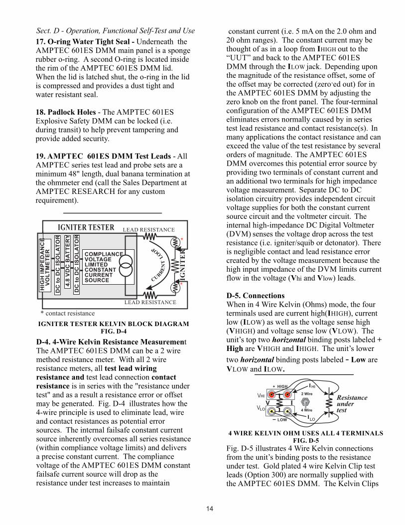
D-4. 4-Wire Kelvin Resistance MeasurementThe AMPTEC 601ES DMM can be a 2 wire method resistance meter. With all 2 wire resistance meters, all test lead wiring resistance and test lead connection contact resistance is in series with the "resistance under test" and as a result a resistance error or offset may be generated. Fig. D-4 illustrates how the 4-wire principle is used to eliminate lead, wire and contact resistances as potential error sources. The internal failsafe constant current source inherently overcomes all series resistance (within compliance voltage limits) and delivers a precise constant current. The compliance voltage of the AMPTEC 601ES DMM constantfailsafe current source will drop as the resistance under test increases to maintain
IGNITER TESTER KELVIN BLOCK DIAGRAMFIG. D-4
constant current (i.e. 5 mA on the 2.0 ohm and 20 ohm ranges). The constant current may be thought of as in a loop from IHIGH out to the “UUT” and back to the AMPTEC 601ES
DMM through the ILOW jack. Depending upon the magnitude of the resistance offset, some of the offset may be corrected (zero’ed out) for in the AMPTEC 601ES DMM by adjusting the zero knob on the front panel. The four-terminal configuration of the AMPTEC 601ES DMM eliminates errors normally caused by in series test lead resistance and contact resistance(s). In many applications the contact resistance and can exceed the value of the test resistance by several orders of magnitude. The AMPTEC 601ES DMM overcomes this potential error source by providing two terminals of constant current and an additional two terminals for high impedance voltage measurement. Separate DC to DC isolation circuitry provides independent circuit voltage supplies for both the constant current source circuit and the voltmeter circuit. The internal high-impedance DC Digital Voltmeter (DVM) senses the voltage drop across the test resistance (i.e. igniter/squib or detonator). There is negligible contact and lead resistance error created by the voltage measurement because the high input impedance of the DVM limits current flow in the voltage (Vhi and Vlow) leads.
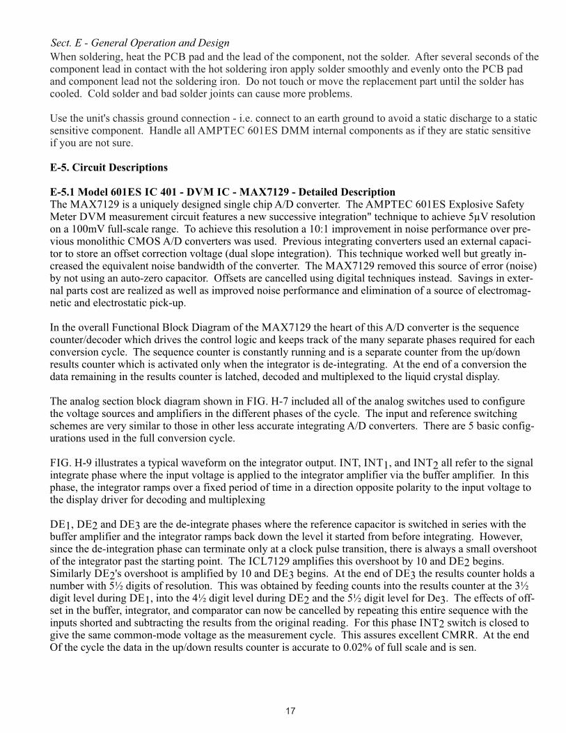
D-5. ConnectionsWhen in 4 Wire Kelvin (Ohms) mode, the four terminals used are current high(IHIGH), current low (ILOW) as well as the voltage sense high (VHIGH) and voltage sense low (VLOW). The unit’s top two horizontal binding posts labeled + High are VHIGH and IHIGH. The unit’s lower
two horizontal binding posts labeled - Low are VLOW and ILOW.
Fig. D-5 illustrates 4 Wire Kelvin connections from the unit’s binding posts to the resistance under test. Gold plated 4 wire Kelvin Clip test leads (Option 300) are normally supplied with the AMPTEC 601ES DMM. The Kelvin Clips
2 Wire
4 Wire
Resistance under test
+ HIGH
LOW
VLO
LO
HI
HI
I
I
I
4 WIRE KELVIN OHM USES ALL 4 TERMINALSFIG. D-5
Sect. D - Operation, Functional Self-Test and Use
14

have an insulator delrin spool that separates the upper jaw from the lower jaw of the clip. With two of the clips you have a 4 wire Kelvin connection.
The 601ES Explosive Safety DMM being a four wire Kelvin resistance meter often time may have Voltage high and Voltage low sense leads open circuited (disconnected) from in everything.When nothing is connected in the four wire resistance mode and if the leads aren't shorted together the display may appear to wander (i.e. "measure" mode with nothing connected). The High Impedance DVM circuit must receive a voltage signal/input to display the proper value. For the 601ES Explosive Safety DMM this is not a problem when Voltage high is shorted to Current high (2 wire method) and Voltage low is shorted to Current low.
The AMPTEC 601ES DMM Series of Safety Meters all incorporate a constant current source design that renders them incapable of delivering excessive voltage or current to the device under test. The fail-safe current (<10mA) for each range is indicated section B of this manual. Please refer to section E-5 for a technical description of the failsafe circuitry specifics.
D-6. Fatigued Adapters and Loose Connections - Common Sources of Measurement Error It is important to avoid too many 2 wire adapters and connections in series with the "resistance under test" if possible. A fatigued test wire harness adapter or wire/plug or a wire splice (i.e. twisted pair) that is loose can become a real intermittent resistance measurement error problem. A fatigued adapter or loose connector, plug, or wire splice will often times changes their contact resistance characteristics as the connection wiring is handled. Loose adapters, connections, and plugs, are potentially one of the largest source of resistance measurement errors and should be recognized and avoided. As a general rule, when it comes to measuring electrical resistance, the fewer the connections you can make to the "device under test" the fewer the problems.
D-7. Battery Monitoring Circuitry - The LCD display will indicate "LO BAT" when it is time to replace the batteries. "LO BAT" If the indicator is displayed, the 601ES DMM readings should not be trusted.
The "LO BAT" will typically come on when the AMPTEC 601ES DMM internal batteries (4 ea. 1.5 VDC alkalines - Duracell Ultra or better) reach approx. 3.6 VDC. To change the batteries remove the screws securing the battery compartment. The back side of the battery compartment cover is lined with a sponge fill neoprene gasket to help provide a water resis-tant battery compartment. Carefully pull the battery holder out and remove the cable-tie securing the batteries. Observe battery polarity when replacing the "AA" batteries. Re-secure the four new batteries in the holder with a new cable tie, then return it to the battery compart-ment and re-secure the compartment lid (screws). See Section A-4 for diagram.
D-8. Failsafe Operation OverviewThe AMPTEC 601ES DMM Series of Safety Meters all incorporate a constant current source design that renders them incapable of delivering excessive voltage or current to the device under test. The fail-safe current (<10mA) for each range is indicated section B of this manual. Please refer to section E-5 for a technical description of the failsafe circuitry specifics.The 601ES Explosive Safety DMM Igniter Tester receives it’s power from an internalre-chargeable battery pack - 4 “AA” batteries housed behind its metal battery box.
Overrange Indication:When the lower portion of the LCD display indicates “>>>OR” the AMPTEC 601ES Explosive Safety DMM is in overrange mode.Make sure the test leads are connected to the “UUT”. The “Overrange State” can occur whenever the measurement terminals are open circuit (not connected to anything), or the measurement under test is “higher than the selected range. The most common way to correct for an “overrange” condition is to select the next higher range. Of course if your already at the highest resistance range, for example (20 kilo Ohm), then the instrument is informing you that the resistance under test is a higher level than 20 kilo Ohms, possibly an “open circuit".
Sect. D - Operation, Functional Self-Test and Use
15

CHAPTER E - GENERAL OPERATION AND DESIGN
E-1. GeneralThe AMPTEC RESEARCH 601ES Explosive Safety DMM Igniter Tester is shown in block diagram form in Figure E-1. All diagrams and information disclosed in this chapter is proprietary and is included in order to make troubleshooting to component level possible.
The AMPTEC 601ES Explosive Safety DMM Series uses modern solid-state semiconductors exclusively and digital CMOS circuits exten-sively to minimize power requirements and make battery operation useful and practical.
AMPTEC RESEARCH also maintains a spare parts inventory of all components found in the 601ES Explosive Safety DMM tester and it’s customer service department can also provide additional assistance in the trouble shooting process.
E-2. TroubleshootingSince the AMPTEC 601ES Explosive Safety DMM Igniter Tester is used to test potential deadly explosive force detonators and warheads of missiles etc., personnel that are not qualified to make such electrical repairs on the 601ES Explosive Safety DMM should not even attempt to remove the calibration access screws or open the main panel or effect any repair whatsoever.
Apparent AMPTEC 601ES Explosive Safety DMM malfunctions can sometimes be the result of bad test lead/connection wiring, wrong connections, misinterpretation of specifications, low battery levels and in rare cases due to an incomplete understanding of the instrument and how to use it. A thorough review of the operat-ing instructions for this instrument is recom-mended prior to any component replacement. Check to be sure that cables and other test equipment are in good working order before attempting to troubleshoot the AMPTEC 601ES Explosive Safety DMM series.
If you turn on the AMPTEC 601ES Explosive Safety DMM and the display does not come on, it may indicate the batteries need changing.
If the AMPTEC 601ES Explosive Safety DMM exhibits problemsthat cannot be eliminated byreviewing Chapters B and D, the following guidelines have been established to help solve the problem.
E-3. Localizing the ProblemThe key to successful troubleshooting is to localize the problem to a general electronic parameter as much as possible before trying to pin the problem down to a specific component. Certain questions should be asked such as "Does the problem occur on all ranges or on a specific range only?" If the AMPTEC 601ES Explosive Safety DMM does not come "on" when powered up, did you check the obvious items such as dead batteries? Is there 5 mA of test current coming out of the units 20 ohm range? The power supplies for both the current source and the digital voltmeter electronics are also one of the first things that should be tested.
As it is not possible to anticipate all possible failure modes of the AMPTEC 601ES Explosive Safety DMM series igniter tester, service personnel should become familiar with this section to gain a complete understanding of the internal workings of this safety meter.
E-4. Component ReplacementIf the malfunction is a faulty component, the accuracy of the AMPTEC 601 Explosive Safety DMM igniter tester can be maintained only if the AMPTEC 601ES is re-calibrated following a component replacement (repair) and the following precautions are taken:
Use only the specified component or its exact equivalent. Spare parts can be ordered from AMPTEC RESEARCH by referring to the AMPTEC Stock Number listed in the Parts Lists section at the back of this manual.
The highest quality 63/37 grade rosin core electronic grade solder with a 50W or lower maximum power soldering iron should be used. Never use an acid core solder as corrosion of components leads and PCB etch loss can occur.
16
When soldering, heat the PCB pad and the lead of the component, not the solder. After several seconds of the component lead in contact with the hot soldering iron apply solder smoothly and evenly onto the PCB pad and component lead not the soldering iron. Do not touch or move the replacement part until the solder has cooled. Cold solder and bad solder joints can cause more problems.
Use the unit's chassis ground connection - i.e. connect to an earth ground to avoid a static discharge to a static sensitive component. Handle all AMPTEC 601ES DMM internal components as if they are static sensitive if you are not sure.
E-5. Circuit Descriptions
E-5.1 Model 601ES IC 401 - DVM IC - MAX7129 - Detailed DescriptionThe MAX7129 is a uniquely designed single chip A/D converter. The AMPTEC 601ES Explosive Safety Meter DVM measurement circuit features a new successive integration" technique to achieve 5µV resolution on a 100mV full-scale range. To achieve this resolution a 10:1 improvement in noise performance over pre-vious monolithic CMOS A/D converters was used. Previous integrating converters used an external capaci-tor to store an offset correction voltage (dual slope integration). This technique worked well but greatly in-creased the equivalent noise bandwidth of the converter. The MAX7129 removed this source of error (noise) by not using an auto-zero capacitor. Offsets are cancelled using digital techniques instead. Savings in exter-nal parts cost are realized as well as improved noise performance and elimination of a source of electromag-netic and electrostatic pick-up.
In the overall Functional Block Diagram of the MAX7129 the heart of this A/D converter is the sequence counter/decoder which drives the control logic and keeps track of the many separate phases required for each conversion cycle. The sequence counter is constantly running and is a separate counter from the up/down results counter which is activated only when the integrator is de-integrating. At the end of a conversion the data remaining in the results counter is latched, decoded and multiplexed to the liquid crystal display.
The analog section block diagram shown in FIG. H-7 included all of the analog switches used to configure the voltage sources and amplifiers in the different phases of the cycle. The input and reference switching schemes are very similar to those in other less accurate integrating A/D converters. There are 5 basic config-urations used in the full conversion cycle.
FIG. H-9 illustrates a typical waveform on the integrator output. INT, INT , and INT all refer to the signal 1 2integrate phase where the input voltage is applied to the integrator amplifier via the buffer amplifier. In this phase, the integrator ramps over a fixed period of time in a direction opposite polarity to the input voltage to the display driver for decoding and multiplexing
DE , DE and DE are the de-integrate phases where the reference capacitor is switched in series with the 1 2 3buffer amplifier and the integrator ramps back down the level it started from before integrating. However, since the de-integration phase can terminate only at a clock pulse transition, there is always a small overshoot of the integrator past the starting point. The ICL7129 amplifies this overshoot by 10 and DE begins. 2Similarly DE 's overshoot is amplified by 10 and DE begins. At the end of DE the results counter holds a 3 32number with 5½ digits of resolution. This was obtained by feeding counts into the results counter at the 3½ digit level during DE , into the 4½ digit level during DE and the 5½ digit level for De . The effects of off-1 2 3 set in the buffer, integrator, and comparator can now be cancelled by repeating this entire sequence with the inputs shorted and subtracting the results from the original reading. For this phase INT switch is closed to 2 give the same common-mode voltage as the measurement cycle. This assures excellent CMRR. At the end Of the cycle the data in the up/down results counter is accurate to 0.02% of full scale and is sen.
Sect. E - General Operation and Design
17

E-5.2 AMPTEC 601ES Resistance The AMPTEC 601ES DMM resistance measurement function works using the principle of OHM'S LAW (V/I=R). It outputs a constant DC current through the unknown resistance then measures the voltage drop across the resistance. The 601ES ohms measurement circuit then scales magnitude and displays the V/I ratio as resistance. For example, the 2 Ohm range outputs a constant 5.0 mA DC. When 5.0 mA passes through a 1.0 Ohm resistor the result is a 5.0 mV drop. We then route the measured voltage drop (i.e. 5.0 mV) into the x10 Amplifier circuit and get 50.0 mV, which is routed into the DVM chip (MAX7129) which drives the LCD display as 1.0000 Ohm. The 20 Ohm range also outputs 5mA of constant failsafe current. When 5 mA is routed through a 10 ohm resister, you get 50mV. which is also routed into the DVM chip (MAX7129) which drives the LCD display as 10.000 Ohms. The 200 Ohm range outputs 500uA. Put that across a 100 Ohm resister and you get 50mV which put into the DVM chip (MAX7129) displays it as 100.00 Ohms. As the range resistance goes up by a factor of 10. The DC current goes down by a factor of 10 keeping the voltage at 50mV.
E-5.3 POWER SUPPLY IC101 is a 5 volt regulator with an enable pin 4. Pin 4 normally sits at +5V through RN101:3 and RN101:1. When the Power switch is pressed SW101 pin 4 is pulled to ground through D101, and +5 is turned on which then goes to IC102 a 5 volt regulator. Once the power is turned on the microprocessor wakes up and turns on TR101, which then holds pin 4 low keeping the power on. Even when the momentary power switch is released. When the power switch is pressed again to turn the unit off TR102 is turned on and a signal is sent to the micro processor and it turns off TR101 which allows pin 4 to go high and turns the power off. The micro can also turn the unit off the same way after a certain time period has elapsed. This is to save battery life. See FIG. H-1.
E-5.4 RELAY CONTROLThe micro can turn on TR201-TR209 using IC201 and IC202. These fets are used to set and reset latching relays on the current board. The connection is made through three ribbon connectors J201, J202, J203. A signal also comes back through these connectors indicating which relay is on and this is used to control the decimal point and K on the display. See FIG. H-2.
E-5.5 MICROPROCESSORIC301 is the microprocessor it can be programed through P301 when JP301 is in the P position and operate when JP301 is in the N position. J302 comes from the front panel range switch to let the micro know which range has been selected. It then sends the necessary signal to IC201 and IC202 on sheet 2 to select the proper FET to turn on the range relay on the current board. JP303 is used to tell the micro which time delay is selected to automatically turn the unit off. It uses PTC1 to turn the power on and off and PTD7 to detect if the power switch was pressed. These lines go to sheet 1. Ic302 is used to tell if it safe to change ranges. See FIG. H-3.
E-5.6 DIGITAL VOLT METERIC402 is an X 10 Amplifier used for the 2 Ohm range. RL401 is used to switch the amplifier in and out. D401 is the reference Zener. RV401 is used to set the reference voltage to 500 milli volts. In the 100 mV measurement mode 50 mV in will display 10000. RL402 is used to switch in an offset in conjunction with the front panel zero pot for the 2 and 20 Ohm ranges. RL403 is used for the 200 Ohm range. Above 200 Ohms on offset is used. P401 is used to send the display information to the front panel LCD display. See FIG. H-4
Sect. E - General Operation and Design
18

CALIBRATION AND MAINTENANCE
F-1. GeneralThis section of the manual contains routine
maintenance information regarding the
AMPTEC RESEARCH 601ES Safety DMM.
Calibration should be performed on a regular
basis to ensure continued instrument accuracy
or following a main PCB electronic component
repair/replacement. The recommended
calibration interval is 1 year.
AMPTEC 601ES DMM Calibration note:For the resistance function, the AMPTEC
601ES Safety DMM must be calibrated using
four wire Kelvin connections to the resistance
standard in order to eliminate lead resistance
and contact resistance errors. The Option “300”
is a gold plated 4 Wire Kelvin Clip Test Lead
set that is available with the AMPTEC 601ES
DMM.
F-2. Required Test EquipmentFollowing standard resistors are required to
calibrate the 601ES Explosive Safety Meter
Igniter Tester .
Precision Resistance Standards: 0.001 ohms ± 0.01% Accuracy 1 ohm ± 0.01% Accuracy 10 ohms ± 0.005% Accuracy 1000 ohms ± 0.005% Accuracy 10 Kohms ± 0.01% Accuracy DC Voltage Standard: 600 V ± 0.05% or better accuracy 100 V ± 0.05% or better accuracy 10 V ± 0.05% or better accuracy 1.0 V ± 0.05% or better accuracy
AC Voltage Standard: verify @ 60Hz 600 V ± 0.05% or better accuracy 100 V ± 0.05% or better accuracy 10 V ± 0.05% or better accuracy 1.0 V ± 0.05% or better accuracy
AC/DC Current Standard: 1.0 ampere ± 0.05% or better accuracy
F-3. Calibration ProcedureA. Function and Verification of Each Ranges
Accuracy - Following a full 15 minute warm-up
period - Verify each function and range with the
appropriate calibration standards to determine if
the AMPTEC 601ES DMM meets its published
accuracy specifications as published in Section B
( p.7). Only the "Out of Specification" functions
( Section B) need to be addressed with any adjust-
ment procedure - If the 601ES meets the specifi-
cations as compared with traceable standards then
it is ready to certify with a calibration sticker etc.
and "No adjustments are needed". The 601ES
DMM requires fully charged batteries and a full 15
minute warm-ip period prior to any adjustments.
The calibration adjustments are accessed by
removing the 10 calibration access screws around
the perimeter of the 601ES DMM front panel, then
lifting off the top plate by the handles. The
locations of the adjustments are shown on drawing
number 601ES Explosive Safety Meter-600 at the
back of this manual. Use caution when lifting the
601ES top panel up by the handles, as there is
umbilical wiring that connects the top panel
electronics to battery pack wiring and chassis/case
ground wiring mounted inside the bottom of the
601ES case. Set the top panel on end resting on the
unit’s bezel.
F-3-1. Zero Offset Adjustment1. Make sure the precision (front panel) zero pot is
turned fully clockwise (next to battery compartment
~ see top plate).2. With the AMPTEC 601ES DMM in 4 Wire
mode, select the 20 Kohm range. Short the four
Wire Kelvin Leads together at the ends.3. Any zero offset greater than the specification (
0.05% of range which is 00.10 on the 20 Kohm
range) then adjust as noted next. If the zero reading
is >00.10 then adjust potentiometer RV405 to be as
AMPTEC RESEARCH 601ES EXPLOSIVE SAFETY DMM
19
2. Keeping all ribbon cables and wiring intact between the various PCBs, carefully remove the DVM PCB from its standoff mounts. (note: one corner of the DVM PCB has a nylon washer acting as an insulator/separator from its corner stand off support). Save this nylon washer as it must be be returned to its PCB metal standoff location when the adjustment procedure is finished. Slightly lift and tilt the right hand side of the DVM PCB to give you access to all the DMM trimpot locations ( needed for voltage and current measurement adjustments). All voltage adjustments should be performed with DC Voltage Standard input then later verify with an AC Voltage Standard. DC Voltage input from a DCV standard pro-vides the most stable AMPTEC 601ES voltage reading for calibration purposes. 3. Select the 600V range and input 0.00 VDC from the DC Voltage standard. Adjust RV101 to read 000.0 volts.4. Still on the 600V range input 600.0 VDC from the DC Voltage standard. Adjust RV102 to read 600.0 volts.5. Select the 200V range and input 100.00 VDC from the DC Voltage standard. Adjust RV105 to read 100.0 volts.6. Select the 20V range and input 10.000 VDC from the DC Voltage standard. Adjust RV104 to read 10.000 volts.7. Select the 2 V range and input 1.0000 VDC from the DC Voltage standard. Adjust RV103 to read 1.000 volts.
8. You may now verify all the above voltage ranges with input from an AC Voltage standard to determine compliance.
A) Select the 600V range and provide 600VAC @60Hz input, then verify the range is in specifi-cation.
B) Select the 200V range and provide 100VAC @60Hz input, then verify the range is in speci-fication.
C) Select the 20V range and provide 10VAC @60Hz input, then verify the range is in specifi-cation.
D) Select the 2 V range and provide 1.0 VAC @60Hz input, then verify the range is in speci-fication.
F-3-6 AC/DC Current Adjustments1) All trimpot adjustments ( i.e RV401) described for this section are also located on the DMM PCB.
close to 00.00 as possible ( its located on the
DVM PCB) (see figure H-14 in the back of the
manual for the DVM PCB location - its the
PCB directly under the battery compartment).
When adjusting RV405, do not over adjust
which is indicated as a negative sign.
F-3-2. Full Scale Adjustment1. Select the 20 Kohm range. Connect the Kel-vin clips to the 10 Kohm standard resistor.2. Adjust RV401 for a display indication of 10.00 Kohms.
F-3-3. 2.0 Ohm Range Adjustments1. Select the 2.0 Ohm range. Connect Kelvin leads to the AMPTEC 601ES Safety DMM. F-3-3. 2.0 Ohm Range Adjustments con'tConnect the test leads to 0.001 ohm standard. 2. Adjust RV403 on the DVM PCB for a dis-play indication of .0010 ohms. 3. Connect the test leads to a 1.0 Ohm resistance standard. Adjust RV402 on the DVM PCB for a reading of 1.0000 ohms. Over adjustment is indicated by a negative polarity sign.
F-3-4. Verification of Each Ranges Accuracy Check the 20 ohm range with a 10 ohm resis-tance standard. Check the 200 ohm range with a 100 ohm resistance standard. Check the 2.0 KOhm range with the 1.0 Kohm Standard Resistor. Check the 20 KOhm range with the 10.0 KOhm Standard Resistor. All resistance ranges must be within the specifications out-lined in Chapter B. There are no adjustments necessary on the 20, 200, & 20 Kohm ranges.
F-3-5 AC/DC Voltage Adjustments
1. The adjustments for this section is difficult to access, we recommend a simple verification check first for all AC/DC Voltage and AC/DC current measurements to first determine if the AMPTEC 601 Safety DMM is adequately in specification. If the AMPTEC 601ES DMM is "in spec" you do not need to perform the adjust-ment procedure described in the steps below. All the adjustments described in this section are performed on the DMM PCB (see figure H-14 for PCB location, the DMM PCB is essentially located below the DVM PCB and the I source PCB).
AMPTEC RESEARCH 601ES EXPLOSIVE SAFETY DMM CALIBRATION PROCEDURE
20
F-3-6 AC/DC Current Adjustments con't2) Select the 2.0 amp range and provide 1.0ampere DC from the DC Current calibrator.
Keep in mind, you have to press/hold the stray
current pushbutton to measure AC/DC current.
Adjust RV401 (located in the middle of the
DMM PCB) to read 1.000 ampere. Verify AC
current with 1.0 amp@ 60Hz input from an
AC/DC Current Calibrator to read within spec
(see section B for specifications)
F-3-7 50mV/5mA Signal Source Adjustments
Since the voltage and current measurements
have just be calibrated in the previous steps, a
verification check of the 50mV and 5 mA signal
source is recommended prior to any signal
source adjustments (only adjust when neces-
sary). Again, keep all ribbon cables and wiring
intact between the PCBs, carefully remove the
I-Source PCB from its standoff mounts.
Slightly lift and tilt the left hand side of the I-
Source PCB to give you access to the DMM
PCB trimpots below it ( needed only for access
to the signal source adjustments).
1.) Select the 2.0 V range. 2.) Press and hold the 50mV/5mA Signal Source
pushbutton. (should be outputting ~50 mV at this
point)3.) Adjust RV501 located on the DMM PCB
(underneath the I-Source PCB) to read .0500 V .4.) Next select the 2 amp range.5.) Press/hold the 50 mV/5mA Signal Source
button at the same time as the 2.0 stray current
press to measure button and note the display
reading. Adjust RV502 and repeat this step 5
dual button press operation until the AMPTEC
601ES reads .0050 A ( 5 milliamperes).
Return both the I-Source PCB and the DVM
PCBs to their standoff PCB mounts. Return the
nylon washer/insulator to the DVM PCB corner
standoff mount. With all ribbon cabling intact,
re-secure both PCBs to their standoff mounts.
Carefully replace the top panel and umbilical
cabling to it's bezel mount and re-secure the
calibration access screws located around the
perimeter of the 601ES top plate.
F-4. Battery Replacement InstructionsThe battery pack replacement process is:To replace low batteries first unscrew the
battery compartment lid and lift. Remove the
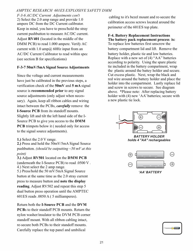
battery holder, plastic tie and low batteries.Replace with a new set of (4) “AA” batteries according to polarity. Using the spare plastic tie included in the battery compartment, wrap the plastic around the battey holder and secure. Cut excess plastic. Next, wrap the black and red wire around the battery holder and place the holder into the compartment. Lastly replace lid and screw in screws to secure. See diagram above. *Please note: After replacing battery holder with (4) new ‘AA’ batteries; secure with a new plastic tie lock.
AMPTEC RESEARCH 601ES EXPLOSIVE SAFETY DMM
‘AA’ BATTERY
BATTERY HOLDERholds 4 "AA" rechargeables
21