Embed Size (px)
Citation preview

MILL DESIGN & MILL OPERATION
BYJ.P. SRIVASTAVAN.S.I, KANPUR

OBJECTIVE OF MILLING
Maximum possible extraction of sucrose
Minimum extraction of non sugars
Minimum sucrose in final bagasse
Optimum moisture in final bagasse
Optimum power/ energy consumption

THRUST AREAS FOR EFFICIENT MILLING
1. CANE MANAGEMENT2. PREPERATION OF CANE3. SPECIFIC FIBRE LOADING4. HYDRAULIC LOAD5. PROPER SETTING OF MILLS6. PRIMERY EXTRACTION 7. SECONDARY EXTRACTION8. IMBIBITION9. MILL SANITATION10. MILL MAINTENANCE

CANE MANAGEMENT
Quality cane supply
Fresh & clean cane
Minimum extraneous matter
Uniform & adequate quantity of cane supply to maintain rated crush rate and avoid reduced crush rate
Thrust area
CANE PREPARATION
Better cane preparation improves bulk density and has higher no of open juice cells and easy to extract free juice from prepared cane. Long fiberous preparation improves mill extraction and reducing the power consumption at mills. Prepared cane should long fibrous shrades to improve feedability to the mills

PREPERATION OF CANE
Optimum cane preparatory Index between 85 to 90
Avoid excess of cane preparatory devices
Avoid dusting of cane
Thrust area

PREPARATORY INDEX
With optimum preparatory index the permeability of bagasse increases & juice cells are opened holding free juice hence extraction become easier. As bagasse approach neutral plane the permeability of bagase reduces and density increases causing low juice extraction

JUICE DRAINAGE
Drainage of juice start from gripping plane and is gradually increased. It is maximum before neutral plane. There is no drainage between neutral plane and axial plane. Thus the air and juice trapped are compressed in this zone due to extrusion. Trapped juice is carried along with bagasse causing re absorption.

SPECIFIC FIBRE LOADING
Optimum loading range ( Sp. Fibre loading )
With TRPF/GRPF 27 kg/m3 to 30 kg/m3
With UFR& D.chute 15kg/m3 to 20 kg/m3
Specific fibre loading = Fibre loading /Diameter
where fiber loading = Af/60∏Dx n x L Kg / m² escribed surface
A crushing rate in kg/hr
f fibre per unit cane
Thrust area

REABSORPTION
Speed of bagasse is lesser than roller surface speed whenit comes in connect at roller gripping zone and reachesequal to roller speed at neutral plane. The speed ofbagasse is higher than roller speed between neutralplane and axial plane. This phenomenon of excess speedcauses the extrusion of bagasse which gives high volumeof bagasse emerged than the escribed volume generatedby rollers. The ratio of actual volume of bagasse toescribed volume at axial plane is called reabsorptionfactor

HYDRAULIC LOAD
a. To be decided by SHP
b. To curb excessive lift of top roller
Thrust area

SPECIFIC HYDRAULIC PRESSUR
SHP = F /0.1 LD
Where F Total load on top roller in
tons
L Length of roller in mt.
D Dia. Of roller in mt.

MEAM VALUE OF SHP TONS/M2 (TONS/FT2)
1ST 2ND 3RD 4TH 5TH
12ROLLER 2582 2367 2690 2958 --
240 220 250 275 --
15 ROLLER 2582 2367 2475 2690 2958
240 220 230 250 275
HYDRAULIC ACCUMULATOR
Nitrogen gas pressure in accumulator should be in the range of 80 to 90% of the hydraulic oil pressure for efficient operation. Nitrogen gas pressure should never be higher than the oil pressure.
PROPER SETTING OF MILLS
Relative positioning of three rollers (Top, Feed & Discharge)
Trash plate properly drawn and positioned
Setting of feeding devices
Proper setting of scrapers knives etc.
Thrust area
MILL SETTING CALCULATIONS
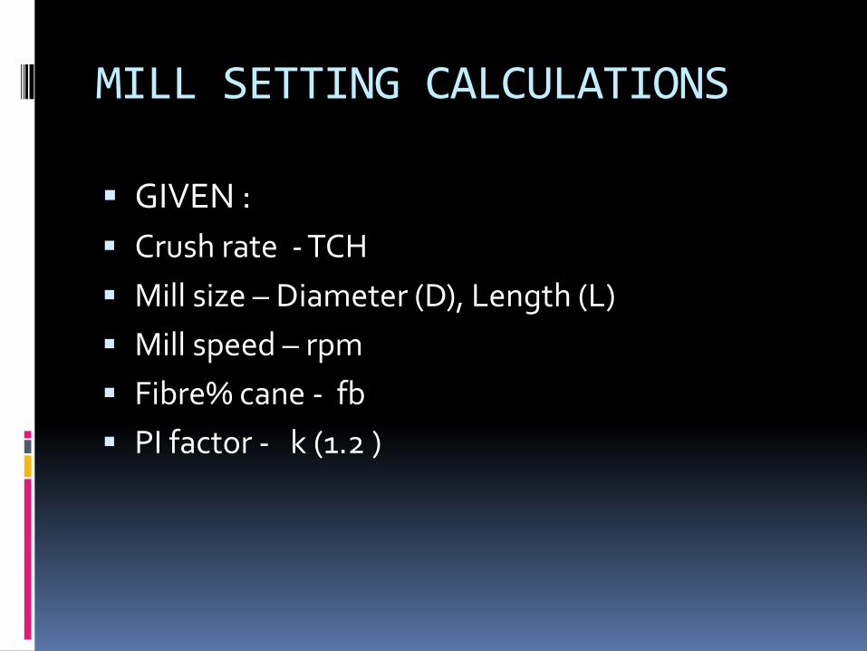
GIVEN :
Crush rate - TCH
Mill size – Diameter (D), Length (L)
Mill speed – rpm
Fibre% cane - fb
PI factor - k (1.2 )

• Assume Fibre%bagasse(q) as under:
1st 2nd 3rd 4th 5th 6th
12 roller mill 33 42 47 5215 roller mill 32 41 47 52 55
18 roller mill 32 40 47 53 50 60
• Wt of bagasse after each mill
w = TCHxfbx1000 kg
q
• Assume bagasse density(d) after each mill
1200 1210 1220 1230 kg/m³

• Discharge opening(operating), Dwo :
Dwo x∏xDxnxLxrx1.2 = w m³
60 d
Dwo = w / 60 x d x ∏xDxnxLxrx1.2 m
Where’ r ’ is Reabsorption factor to be taken as under:
1st mill 1.33
2nd mill 1.33
3rd mill 1.33
4th mill 1.36

Feed work opening:1st 2nd 3rd 4th
F/D conventional 2.0 1.9 1.85 1.8
TRPF/GRPF 1.75 1.7 1.65 1.60
Trash plate setting
TP/F conventional 1.9 2.0 2.1 2.2
TRPF/GRPF 1.7 1.75 1.8 1.8

Roller lift (mm)
Following roller lift is taken
1 2 3 4
F/D 10 10 8 8
TP 12 12 10 10
Mill setting at rest-
Subtract above lift of top roller from operating feed & discharge and TP setting

Neutral plane


Slope to trash plate profile towards discharge roller is given - 6%
Toe point of trash plate is located on root circle of feed roller at an angle of 13° from centre line of feed and top roller
Angle of heel point with centre line of discharge and top roller preferably should be maintained around 25°

MILL FEEDING DEVICES

In early age of sugar industry, feeding of cane and bagasse were made through open gravity chute and apron type cane carrier respectively
The feeding force applicable during this type of feeding was only frictional force applied between Roll surface and material of feed i.e cane or bagasse

The maximum angle of contact for Zero applied feed pressure ( other than frictional force ) would be angle β.
Experiment shows that the maximum value of μ ( frictional coefficient ) does not often exceed to 0.6. Hence
Tan ̅ˡ 0.6 = 31°

It is therefore clear that under frictional force only ( no external feeding pressure ) , the maximum contact angle would be 31° .
For greater contact angle of the order of 50 or more the application of some external feed pressure by introduction of feeding devices be an essential component of a feeding theory.

The external feed devices provided now a days are :
1. UFR
2. Donnelly Chute
3. TRPF
4. GRPF
5. TRF

Axial plane
Neutral plane
Delivery pressureFeed pressure

Frictional theory for cane feeding
dF/dθ = PD cosθ ( tanθ – μ )
This is the differential equation for forces onroll surface . This equation may be used todevelop theories both for pressure requiredto feed the cane /bagasse to pass of rollersand for pressure build up by the feeding roll.

In above equation
F is the horizontal force between elements ofcane /bagasse per unit length of roller
P = Normal force per unit area of roll surface
μ = Ratio of tangential to the radial force onan element of the roll surface. It has amaximum value equal to coefficient offriction between the cane/bagasse materialand the roll surface

Fr Ft
θ θ
Fr sinθ Ft cosθ
dθ
θ F Cane/bagasse
F F+ dF
Fr sinθ
Ft cosθ
Fr
Ft
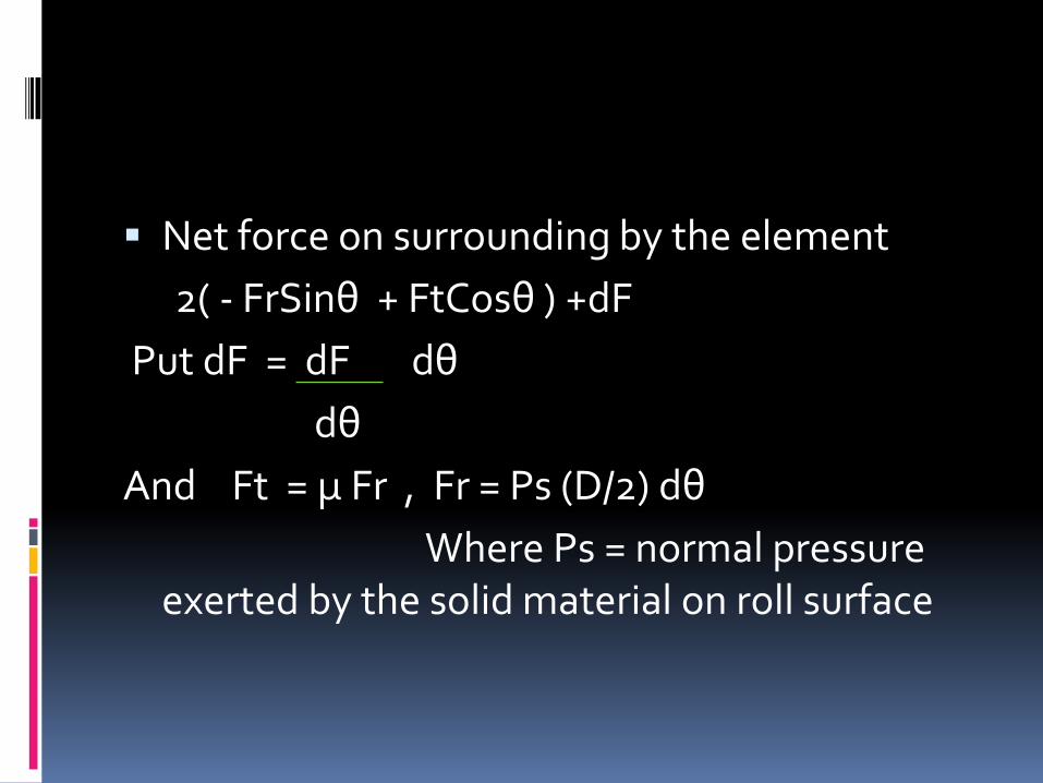
Net force on surrounding by the element
2( - FrSinθ + FtCosθ ) +dF
Put dF = dF dθ
dθ
And Ft = μ Fr , Fr = Ps (D/2) dθ
Where Ps = normal pressure exerted by the solid material on roll surface

-2 Ps (D/2) Sinθ dθ + 2μ Ps (D/2) dθ Cosθ
+ dF dθ
dθ
[ dF/dθ – PsDCosθ ( tanθ – μ ) ] dθ ------1
Put above equation equal to zero, Hence
dF/dθ = Ps D Cosθ ( tanθ – μ )

GRPF/TRPF SETTING
Speed ratio: It is the ratio of surface speed of pressure feeder to surface speed of mill roller
Speed ratio for TRPF 1 to 1.2
Speed ratio for GRPF 1.2 to 1.5
Volumetric ratio. It is the ratio of escribed volume of pressure feeder to escribed volume by mill roller
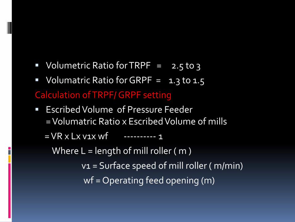
Volumetric Ratio for TRPF = 2.5 to 3
Volumatric Ratio for GRPF = 1.3 to 1.5
Calculation of TRPF/ GRPF setting
Escribed Volume of Pressure Feeder = Volumatric Ratio x Escribed Volume of mills
= VR x Lx v1x wf ---------- 1
Where L = length of mill roller ( m )
v1 = Surface speed of mill roller ( m/min)
wf = Operating feed opening (m)

PRESSURE CHUTE SETTING
Escribed volume of pressure feeder
= L x v2 x Wpf ----------- 2
Where L = Length of pressure feeder (m )
v2 = Surface speed of pressure feeder
wpf = pressure feeder opening
Equate equation 1 and 2, therefore
L x v2 x Wpf = VR x Lx v1x wf
Wpf = VR x Lx v1x wf / L x v2

Pressure Chute Inlet (d1)
Lx v1Cosθ1 x d1 = K/φ ---- 1
where φ = Fibre compaction
= 100 to 130 kg/m3
K = Kg fibre /min
Cos θ1 =( Dpf + Wpf – d1 ) ---- 2
Dpf
Calculate d1 ?

Pressure feeder
θ1
Pressure Chute
V1 d
wpf

Pressure Chute Outlet(d2)
LxV2x Cosθ2xd2 = K/φ ---------- 1
where k = Fibre/min
φ = 80 to125 kg/m3
Cosθ2 = ( D + Wf - d2 ) ---------- 2
D
Calculate ‘d2’ from equation 1& 2


VALUE OF FIBRE COMPACTION(φ)
φ ( kg/ m³)
D.Chute 50 to 80
UFR 80 to 90
Pressure feeder 100 to 130
Pressure chute inlet 100 to 130
Pressure chute outlet 80 to 125

UFR SETTING
• UFR rpm(n1) = 1.1 x Mill rpm(n)
• Average roller speed(nav)=(n1 + n)/2
• UFR length = L
• Average PCD of rollers= D
• Fibre Compaction (φ )= 80 to 90 kg/m³
• UFR setting= Fibre/minx1000
πDnav xLx φ
•

DONNELLY CHUTE SETTING
d
UFR Top Top v
wo θ
vcosθ
Feed
v = Av.speed of rollers
θ = angle of contact

L x v cosθ x d = Fibre/min x 1000/φ
cosθ = Fibre/minx1000/φxLxvxd ---- 1
Where φ = 50 to 80kg/m³
cosθ = DT + wo –d ------ 2
DT
Calculate ‘ d’ from equation 1 & 2

PRIMERY EXTRACTION
High purity extraction
To be achieved maximum
Thrust area

SECONDARY EXTRACTION
Low purity extraction
Extraction based on imbibition efficiency
Extraction of more non sugars
High power consumption
Thrust area

IMBIBITION
By cold water
By hot water
Optimum temperature of hot water 70oC to 75oC
Thrust area
JUICE DRAINAGE
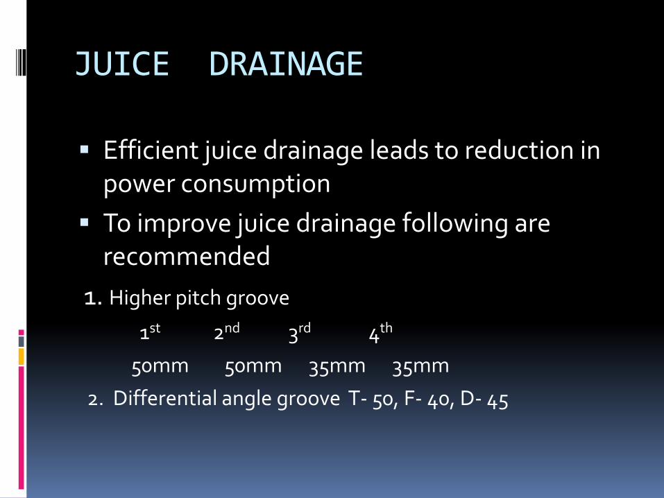
Efficient juice drainage leads to reduction in power consumption
To improve juice drainage following are recommended
1. Higher pitch groove
1st 2nd 3rd 4th
50mm 50mm 35mm 35mm
2. Differential angle groove T- 50, F- 40, D- 45

3. Messchert groove in feed rollers
4. All top rollers are lotus roll
5. Flangeless top rollers with static collar
Thin juice extraction by TRPF/GRPF which reduce load on mill

MILL SANITATION
To avoid bacterial growth
Rapid growth of Luconostres in acidic and Low Brix juice
Regular steaming
Regular chemical spray
Thrust area

NORMAL MILL PRACTICES
Not to monitor lift of top roller
It is assumed that top roller lifts only that value considered during mill setting calculations
Normally actual lift of top roller during operation is higher than considered in mill setting calculation
Higher thickness of cane/bagasse blanket passes through mills due to excessive lift of top roller
This leads to poor extraction of sucrose and results in higher sugar loss in final bagasse
Hydraulic load applies on top roller simply by assumption/experience
It is seldom to consider the lift of top roller while deciding the hydraulic pressure
To compromise with mill performance due to power constrain

PERFORMANCE OF INDIVIDUAL MILLS
Plotting of Brix curve for feed and discharge side
To monitor lift of top roller
Analysis of bagasse leaving the mills for free poland total pol
Measurement of temperature of juice on feed anddischarge
Measurement of pol for bagasse leaving a mill andjuice from back roller of same mill

OVER-ALL PERFORMANCE OF MILLS
Pol percent final bagasse
Brix of last expressed juice
Primary extraction (PE)
Reduced mill extraction (RME)

POINTS FOR IMPROVING EXTRACTION
Proper hydraulic pressure by maintaining Nitrogen pressure in bladder i.e.80 to 90% of oil pressure
Lift of top roller should be within limit and top roller should freely float
Mill imbibition should be minimum 230 % on fibre and higher value is subjected to evaporater capacity
Trash plate heel angle with discharge roller center line should be around 25º
Trash plate heel clearance should be maintained carefully to have better drainage
Scrapper and trash plate groove angle should be lesser than roller groove angle by 5º to 6º

• All mills should run under optimum loads
• Installation of ACFC (Auto cane feeding control ) system to ensures:
1. Uniform feeding to mills
2. Reduce down time at preparatory devices
3. Uniform blanket thickness

4. Loading on motors is uniform, kick loads are avoided

MAINTENANCE FOR QUALITY PRODUCTION
AIM OF MAINTENANCE IS TO KEEP DOWN TIMEMINIMUM AND TO ACHIEVE DESIRED CAPACITYUTILIZATION WITH EFFICIENCY AND QUALITYPRODUCTIVITY

PRESENT STATUS OF MAINTENANCE
There is seldom preventive/predictivemaintenance
No records of individual equipments
No records about repair of equipments
No proper training programme
No proper house keeping works
No separate inspection cell
Lack of motivation among staff

PROPER MAINTENANCE SYSTEM
Complete repair and overhauling during off-season
Preventive/ predictive maintenance duringcrushing season

STEPS FOR GOOD MAINTENANCE
Right selection of equipments and theircomponents
Correct orientation of wrongly placedequipments
Quality repair during off-season
Planning and scheduling of various jobs
Equipment cards
Provision of stand by equipments

PREVENTIVE MAINTENANCE
CONSTANT MONITORING ON OPERATIONALPARAMETERS THROUGH SYSTEMATICINSPECTION SO AS TO TAKE TIMELYREPAIR/REPLACEMENT OF COMPONENTSUNDERGOING WEAR AND TEAR TO AVOIDDOWNTIME DUE TO FAILURE
ELEMENTS OF PREVENTIVE MAINTENANCE
Preventive maintenance cell with propermotivation
Proper inventory to be maintained
Categorization of plant and machinery
Analysis of wear and tear and evaluation ofservice life

PREDICTIVE MAINTENANCE
IT IS MORE ADVANCE ON STREAM NONDESTRUCTIVE TESTING WITH A VIEW TO AVOIDUNNECESSARY SHUT DOWNS BY TAKING FULLHELP OF TROUBLE PREDICTING AND TROUBLESHOOTING TEST INSTRUMENTS