Embed Size (px)
Citation preview
MODELLING OF A SUGAR CANE MILL
K.R.Pati1 Sugar Engineering Division
Vasantdada Sugar Institute, Pune, India.
ABSTRACT
A Sugar mill is an inherent part of most of the szlgarcane juice extraction systems like milling tandem, d?ffilser or even low-presszlre extraction system. Hence it is very imperative to have detailed anolysis of forces acting in sugar cane mill head stock. In sugar machinery the most intrinsic equipment is szlgar mill and pnrticzdarlv the mill head stock or cheek. The nature of forces acting dz~ring cone crzishing is a very complex phenomenon and needs analysis of mechnnical parmeters like force, torque, powel; speed and the eccentricity.
I
27?e purpose of this stirdy is to present and analyze mechanical para1netes.s to have exact idea about Ionding at variozis locntions of mill head stock Eccentricity in mills is a term, which is confused by nzill engirieefiv, m i s stztdy expresses the importance of eccentricity to be provided in the mill. Each of these pnrarneter is zlsefill in designing of mechanical components and in achieving an optimistic design of the inill to deliver smooth jlnctioning during operatiort. Optirnzlin design means the maximum extraction of juice with least power consumption.
Rztssel and Mztrry presented experimental eqzrations .for estimnting forces and torque in a pair of rolls as a .function of the characteristics of szlgarcme, dimension of rollers and mill settings. Hzlgot (1986) calcztlated inill power based on the mszimption that the vertical load on the turn h plate is 25% of the vertical load on the rollel:
1
7Iie force loading based on the principles and equations applied in this analysis have been used E
for design of 42" x 84" inill size head stocks and these are operating satisfactorily in India. j I
Kqtrlortls : Sugar mill head stock loading, mntheinatical nzodelling, eccentricity in nzill, analysis of I <forces in sugar mill. I
I
A mpdel is an idealization of a real-world situation that aids in the analysis of a problem. A model may be either descriptive or prescriptive. A descriptive model enables us to understand a real-world system or phenomenon like cutaway model of an aircraft gas turbine, pump etc. Such a model serves as a device for communicating ideas and infonnation. However it does not help LIS to predict the behavior of the system. A prescriptive model is used primarily in engineering design because it helps us both understand and predict tke performance of the system. Mathematical nod el ling is adopted many times to analyze a complex engineering system.
SYSTEM ENGINEERLNG
Engineers use models for thinking, comm~uiication, prediction, control for many engineering problems to deal with complex situations. E~igineering systems frequently are very complex and needs breaking the system into simpler components and modeling each of them. In doing that allowance must be made for the interaction of the components with each other. Techniques for treating large and conlplex system by isolating the critical components and modeling them are at the heart of the growing discipline called System Engineering.
Once the chief components of the system have been identified the next step is to list the important input and output parameters those describe and determinc the behavior of the system. The various parameters are related to each other by appropriate mathematical laws. The relations transform the input parameters to output through algebraic or integral equations. The solution of these equations is the last step in the modelling process.
METHODS
The construction of sugar cane nlill is a complex assembly containing feed roller, top roller, discharge roller: force feed roller, trash plate. crown pinions etc. All these components are then housed in head stock assembly. Hence while carrying out the analysis of the whole system, it is broken into an isolated or independent componci~ts as a free body. Interactions of parameters thus are established to formulate the mathematical laws with the help of algebraic equations. These equations with known inputs are then solved to get the final solution.
The main independent components of the system are:
A) Feed roller with its crown wheel. B) Discharge roller with its crown wheel. C) Bearing and trash plate reactions. D) Extension to fourth roller application.
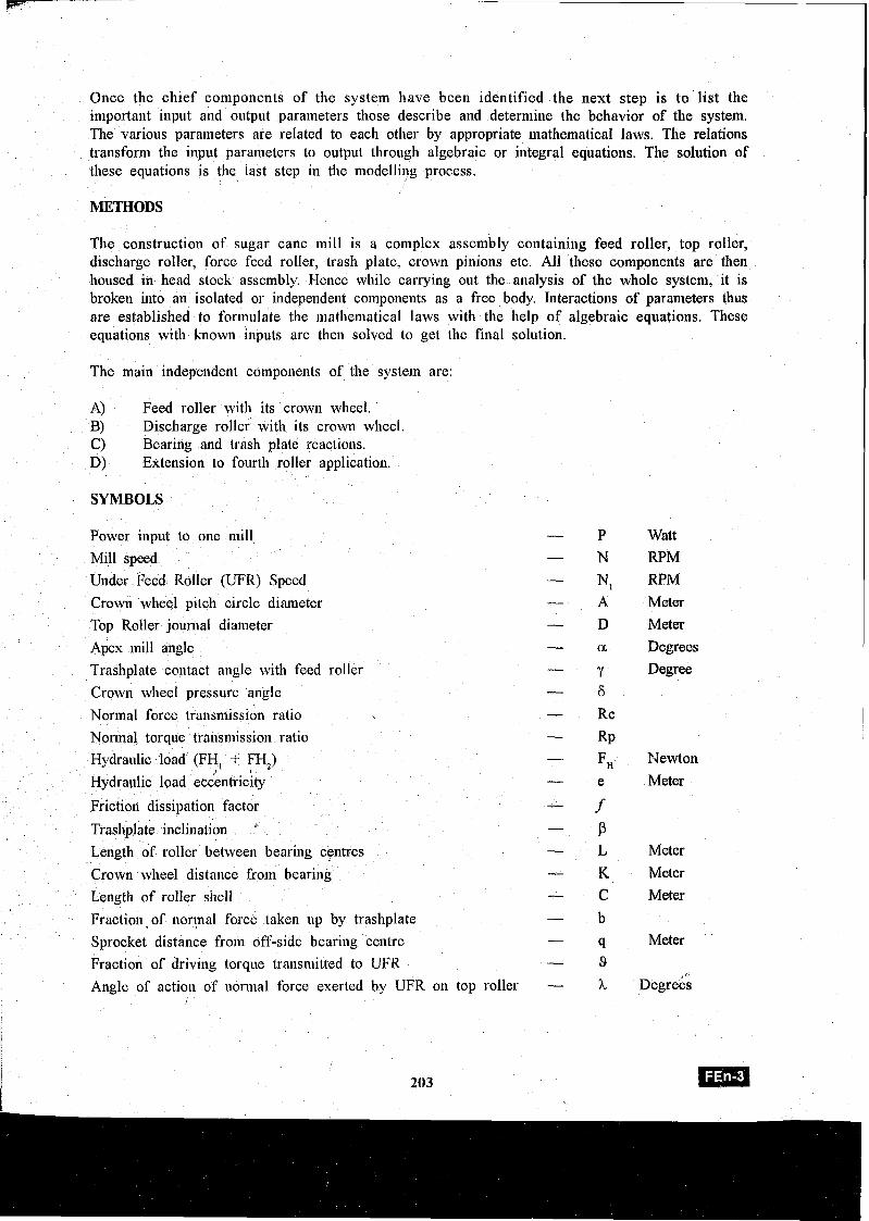
SYMBOLS
Power input to one lnill - P
Mill speed - N
Under Feed Roller (UFR) Speed - -
N, Crown wheel pitch circle diameter A Top Roller journal diameter - D
Apex mill angle - a
Trashplate contact angle with feed roller - Y Crown whecl pressure angle - 6 Normal force transmission ratio - Rc
Normal torque transmission ratio - RP Hydraulic load (FH, + FH,) - 51 Hydraulic load ecLentricky - e
Friction dissipation factor - . f Trashplate inclination ~ P Length of roller between bearing centres - L Crown wheel distance from bearing - K Length of roller shell - C Fraction,of nort,nal force taken up by trashplate - b
Sprocket distance from off-side bearing centre - 9
Fraction of driving torque transmitted to UFR - 9 Angle of action of normal force exerted by UFR on top roller - 3L
I
Watt
RPM RPM
Meter
Meter
Degrees
Degree
Newton
Meter
Meter
Meter
Meter
Meter '
Degrees
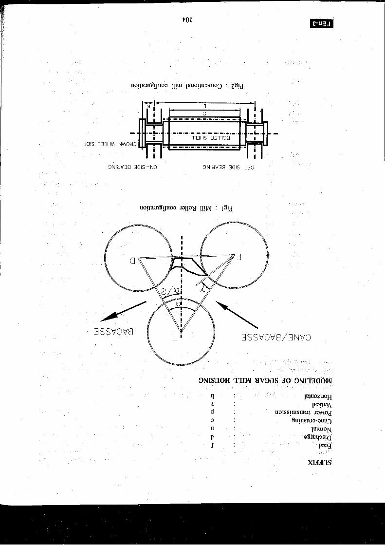
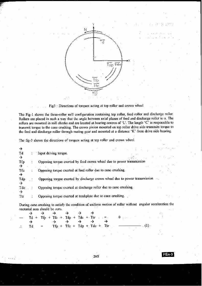
Fig3 : Directions of torques acting at top roller and crown wheel
The Fig-1 shows the three-roller mill coniiguration containing top roller, feed roller and discbarge roller. Rollers are placed in such a way that the angle between axial planes of feed and discharge roller is a. The rollers are mounted in mill cheeks and are located at bearing centres of 'L'. The length 'C' is responsible to transmit torque to the cane crushing. The crown pinion mounted on top roller drive side transmits torque to the feed and discharge roller through mating gear and mounted at a distance 'K' from drive side bearing.
The fig-3 shows the directions of torques acting at top roller and crown wheel.
+ Td + Tfp + Tfc + T ~ P + Tdc + Ttr
: Input driving torque.
: Opposing torque exerted by feed crown wheel due to power Gansmission
: Opposing torque exerted at feed roller due to cane crushing.
: Opposiyg torque exerted by discharge crown wheel due to power transmission
: Opposing torque exerted at discharge roller due to cane crushing.
: Opposing torque exerted at trashplate due to cane crushing. ,
During cane crushing to satisfy the condition of uniform motion of roller without angular acceleration the vectorial sum should be zero. + + + + + + - Td + Tfp + Tfc + Tdp + Tdc + Ttr = 0
+ + + + + + :. Td = Tfp + Tfc + Tdp + Tdc + Ttr (1)
FEED ROLLER WITH ITS CROWN WHEEL.
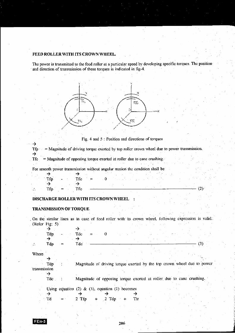
The power is transinitted to the feed roller at a particular speed by developing specific torques. The position and direction of translnission of these torques is indicated in fig4.
Fig. 4 and 5 : Position and directions of torques 3 Tfp = Magnitude of driving torque exerted by top roller crown wheel due to power transmission. + Tfc = Magnitude of opposiag torque exerted at roller due to cane crushing.
For srnootll power transmission without angular motion the condition shall be 3 3 Tfp - Tfc = 0 + +
. . Tfp = Tfc (2)
DISCHARGE ROLLER WITH ITS CROWN WHEEL :
TRANSMISSION OF TORQUE
. On the similar lines as in case of feed roller with its crown wheel, following expression is valid. (Refer Fig: 5) + -3
Tdp - Tdc = 0 3 +
. . Tdp = Tdc ' (3)
Where 3 Tdp : Magnitude of driving torque exerted by the top crown wheel due to :power
transmission 3 Tdc : Magnitude of opposillg torque exerted at roller due to cane crushing.
Using equation (2) & (3), equation (1) becomes + 3 + -3 Td = 2 Tfp + 2 Tdp + Ttr
\
Em 206
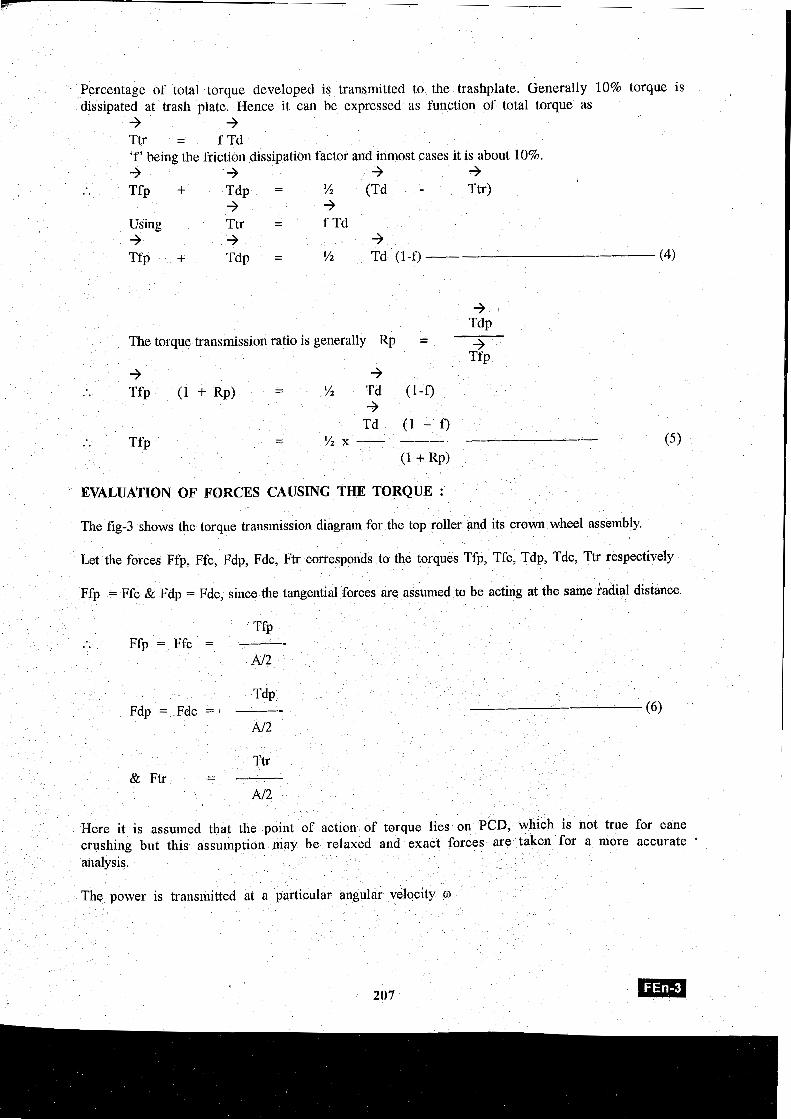
Percentage of total torque developed is transmitted to the trashplate. Generally 10% torque is dissipated at trash plate. Hence it can be expressed as function of total torque as
+' + Ttr = f Td 'f' being the friction dissipation factor and inmost cases it is about 10%. + + + + I
. . Tfp + Tdp = % (Td - Ttr) + +
Using Ttr = f Td + +' + Tfp + Tdp = '/2 Td (1-f) (4)
The torque transmission ratio is generally Rp =
+ T ~ P +'
Tfp
Td (1 - f ) Tfp
- % x - --A --- - I - . . ( 5
(1 + RP)
EVALUATION OF FORCES CAUSING THE TORQUE :
The f ig3 shows the torque transmission diagram for the top roller and its crown wheel assembly.
Let the forces Ffp, Ffc, Fdp, Fdc, Ftr corresponds to the torques Tfp, Tfc, Tdp, Tdc, Ttr respectively
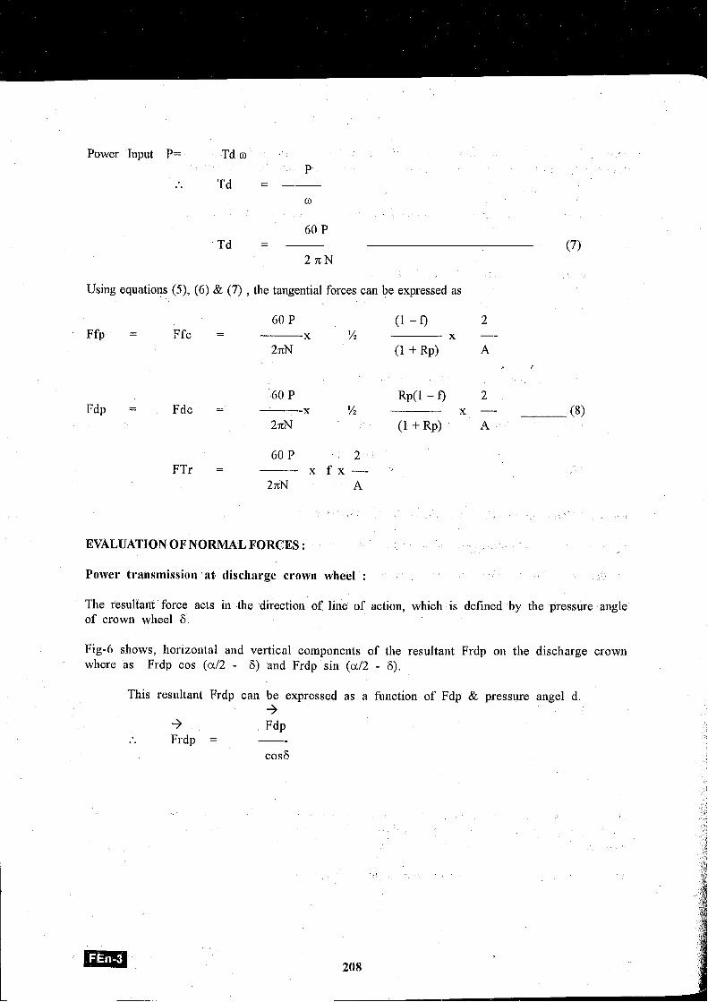
Power Input P= Td w , #
P . . Td = ---
Using equatioiis (9, (6) & (7) , the tangential forces can be expressed as
60 P 2 --
(1 - f) Ffp = Ffc = x !4 x --
2nN (1 + RP) A f
60 P 2 -- Rp(l - f)
Fdp = Fdc = x !4 x -- (8) 27cN (1 + RP) A
60 P 2 FTr = x f x - -
27cN A
EVALUATION OFNORMAL FORCES :
Power t~~ansrnission at discharge crown wheel :
The resultaiit force acts in the direction of line of action, which is defined by the pressure angle of crown wheel 6.
Fig-6 shows, horizontal and vertical cotnponents of the resultant Frdp on the discharge crown where as Frdp cos (a12 - 6) and Frdp sin (a12 - 6).
This resultant Frdp can be expressed as a function of Fdp & pressure angel d. +
3 Fdp . . Frdp = --
cos6
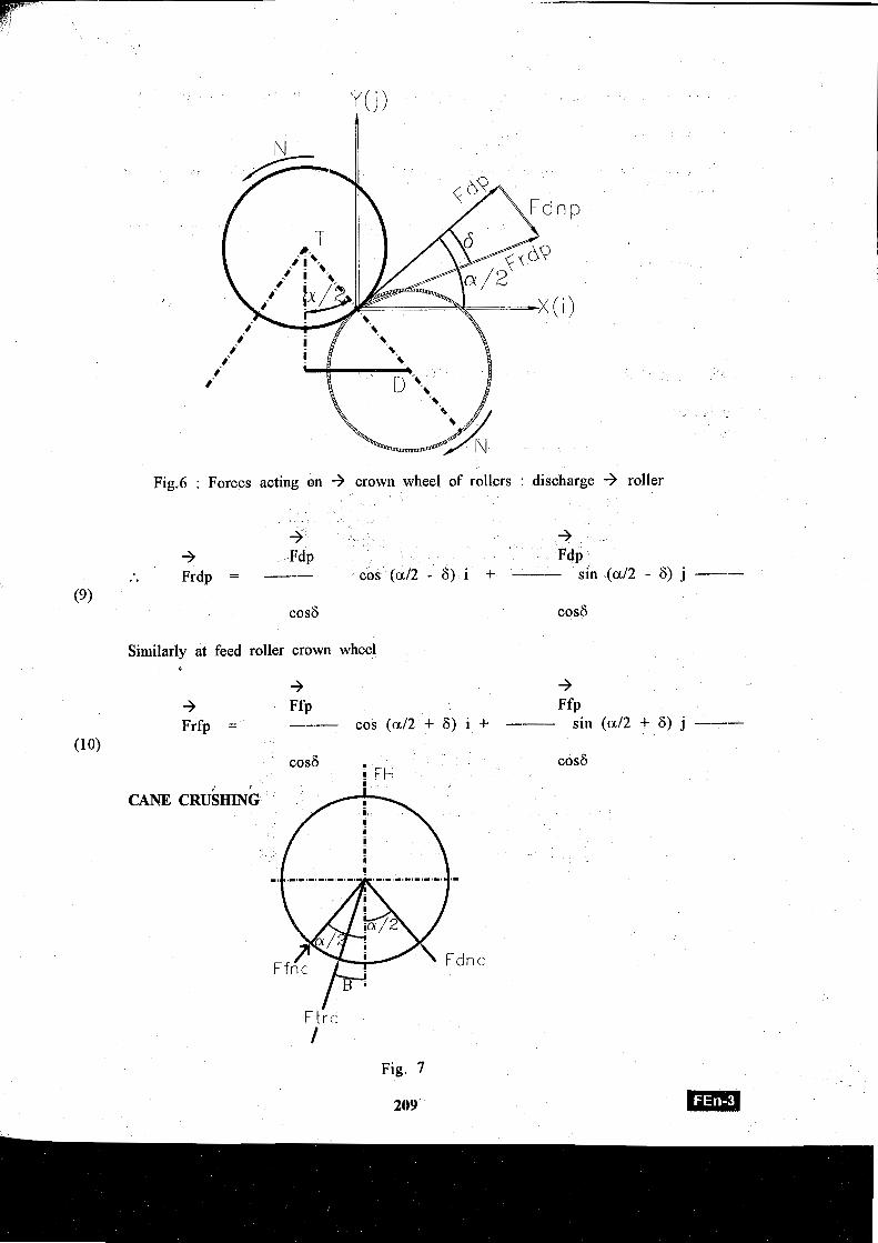
Fig.6 : Forces acting on -3 crown wheel of rollers : discharge -3 roller
3 -3 -3 F ~ P F ~ P Frdp = -- cos (a12 - 6) i + -- sin (a12 - 6) j --
Similarly at feed roller crown wheel C
3 3 -3 Ffp Ffp Frfp = --- cos (a12 + 6) i + --- sin (a12 + 6) j ---
cos6 cos6 FH
CANE CRUSHING
Ft rc 1
Fig. 7
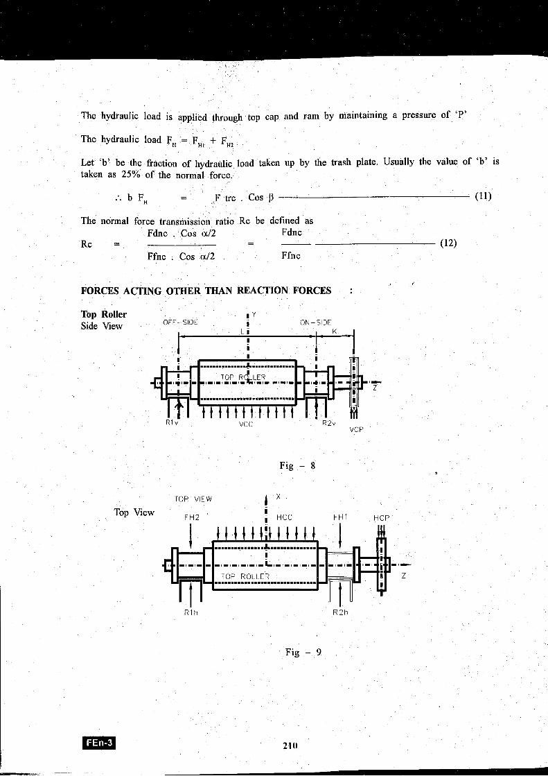
The hydraulic load is applied through top cap and ram by maintaining a presswe of 'P'
The hydraulic load F, = F,, + F,,
Let 'b7 be the fraction of llydraulic load taken up by the trash plate. Usually the value of 'b7 is taken as 25% of the normal force.
:. b F, - - , F trc . Cos p (11)
The normal force transmission ratio Rc be defined as Fdnc . Cos a12 Fdnc
Rc = - (12) Ffnc . Cos a12 Ffnc
I
FORCES ACTING OTHER THAN REACTION FORCES :
Top Roller OFT-SIDE !
Side View ! ON-SIDE
I D z
R l v VCC R2v vc;p
Fig - 8
, TOP VIEW
Top View ! I
FH2 ' , HCC FH 1 H CP
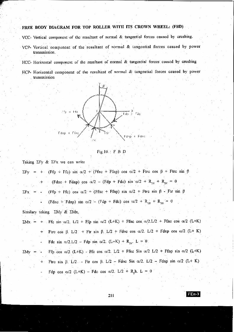
FREE BODY DIAGRAM FOR TOP ROLLER WITH ITS CROWN WHEEL: (FBD)
VCC- Vertical component of the resultant of normal & tangential forces caused by crushing.
VCP- Vertical component of the resultant of normal & tangential forces caused by power transmission.
HCC- Horizontal component of the resultant of normal & tangential forces caused by crushing
HCP- Horizontal component of the resultant of normal & tangential forces caused by power transmission
F t r c
Fig.10 : F B D
Taking CFy & CFx we can write
CFy = + (Ffp + Ffc) sin a12 + (Ffnc + Ffnp) cos a12 + Ftrc cos P + Ftrc sin p
+ (Fdnc + Fdnp) cos a12 - (Fdp + Fdc) sin a12 + R,, + R,, = 0
CFx = - (Ffp + Ffc) cos a / 2 + (Ffnc + Ffnp) sin a12 + Ftrc sin P - Ftr sin P
- (Fdnc + Fdnp) sin a /2 - (Fdp + Fdc) cos a12 + R,, + R,, = 0
Similary taking CMy & CMx,
CMx = + Ffc sill a /2. L/2 + Ffp sin a12 (L+K) + Ffnc cos aI2.Ll2 + Ffnc cos a12 (L+K)
+ Ftrc cos j3. Ll2 + Ftr sill P. Ll2 + Fdnc cos 0112. L/2 + Fdnp cos a12 (L+ K)
- Fdc sin a/2.L/2 - Fdp sin a/2. (L+K) + R,,. L = 0 I
- Ffp cos d2 (L+K) - Ffc cos a12. L12 + Ffnc Sin a12 L/2 + Ffnp sin d 2 (L+K)
+ Ftrc sin p. LIZ - Ftr cos P. L/2 - Fdnc Sin al2. Ll2 - Fdnp sin a12 (L+ K)
- Fdp cos a12 (L+K) - Fdc cos a l2 . Ll2 + R,h. L = 0
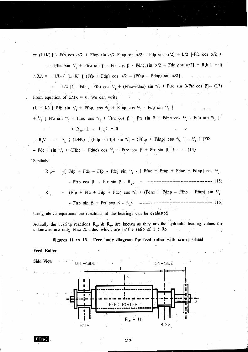
* (L+K) [ -. Ffp cos a12 + Ffnp sin a/2-Fdnp sin d 2 - Fdp cos a/2] + L/2 [-Ffc cos a/2 +
Ffnc sin "1, + Ftrc sill p - Ftr cos P - Fdnc sin a12 - Fdc cos' a121 + R,h.L = 0
:.&11 = 1/L { (L+K) [ (Ffp + Fdp) cos a12 - (Ffnp - Fdnp) sin a121
- L/2 [( - Fdc - Ffc) cos "1, + (Ffnc-Fdnc) sin "1, + Ftrc sin P-Ftr cos PI-- (13)
From equation of CMx = 0, We can write
(L + K) [ Ffp sin "1, + Ffnp. cos "1, + Fdnp cos "1, - Fdp sin "I, 1
+ [ Ffc sin "1, + Ffnc cos "1, + Ftrc cos P + Ftr sin P + Fdnc cos "I, - Fdc sin "I, ]
:. &V = '1, { (L+K) [ (Fdp - Ffp) sin "1, - (Ffnp + Fdnp) cos "1, ] - [ (Ffc
- Fdc ) sin "I, + (Ffnc + Fdnc) cos "/, + Ftrc cos P + Ftr sin PI ) ----- (14)
Similarly
R,,= +[ Fdp + Fdc - Ffp - Ffc] sin "I, - [ Ffnc + Ffnp + Fdnc + Fdnp] cos "I,
- Ftrc cos p - Ftr sin P - R,, ---------------- ------------ ----------------- - (15)
R l h = (Ffp + Ffc + Fdp + Fdc) cos "/, + (Fdnc + Fdnp - Ffnc - Ffilp) sin "1,
Using above equations the reactions at the bearings can be evaluated
Actually the bearing reactions R,, & &, are known as they are the hydraulic loading values the unknowns are only Ffnc & Fdnc whioh are in the ratio of 1 : Rc
Figures 11 to 13 : Free body diagram for feed roller with crown wheel
Feed Roller
Side View OFF- SIDE ON-SIDE
I R f l v
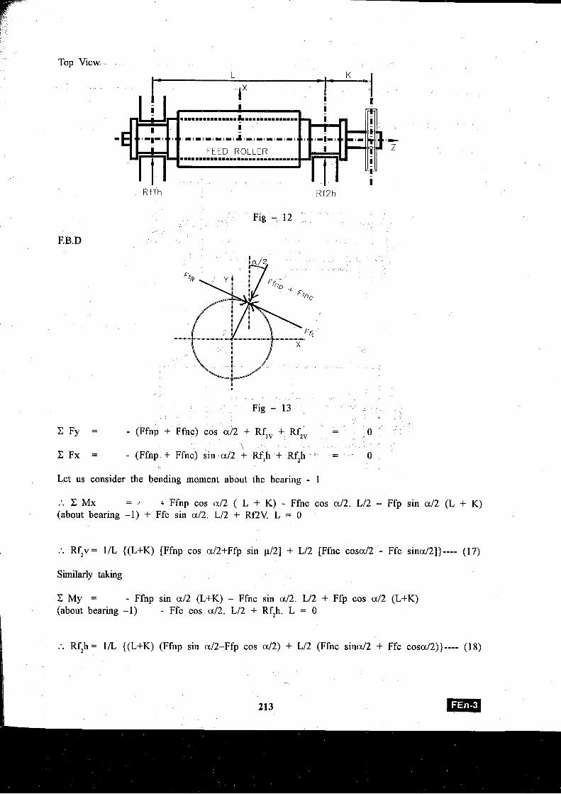
Top View
R f l h Rf2h
Fig - 12
I
Fig - 13
C F y = - (Ffnp + Ffnc) cos a12 + Rf,, + Rf,, - - 0
\ C F x = - (Ffnp + Ffilc) sin a12 + Rf,h + Rf,h - - 0
Let us consider the bending moment about the bearing - 1
:. C Mx - - Ffnp cos a12 ( L + K) - Ffnc cos al2. L12 - Ffp sin a12 (L + K) (about bearing -1) + Ffc sin a12. Ll2 + Rf2V. L = 0
:. Rf,v = 11L {(L+K) [Ffnp cos a/2+Ffp sin p/2] + L12 [Ffnc cosaI2 - Ffc sinal21)---- (17)
Similarly taking
C M y = - Ffnp sin a12 (L+K) - Ffnc sin al2. L12 + Ffp cos a12 (L+K)
I (about bearing -1) - Ffc cos 1x12. L/2 + Rf,h. L = 0
:. R . h = 1/L {(L+K) (Ffnp sin al2-Ffp cos a/2) + L/2 (Ffnc sinal2 + Ffc cosaI2))---- (18)
213 Em 1
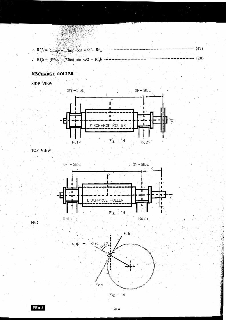
Rf,, ............................................................ (19)
ON-SIDE
TOP VIEW
OFF- SIDE ON-SIDE
Rdl I1
Fig - 16
21 4
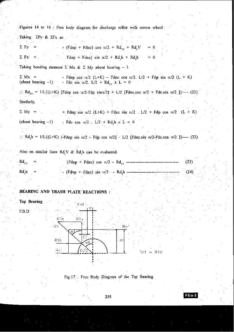
Figures 14 to 16 : Free body diagram for discharge roller with crown wheel
Taking CFy & CFx as
C F y = - (Fdnp + Fdnc) cos a12 + Rd,, + Rd,V = 0
Fdnp + Fdnc) sin a12 + Rd,h + Rd,h = 0
Taking bending inoment C Mx & C My about bearing - 1
C M x = - Fdng cos a12 (L+K) - Fdnc cos al2. L/2 + Fdp sin a12 (L + K) (about bearing -1) - Fdc sin a/2. L/2 + Rd,, x L = 0
.'. Rd,, = lIL{(L+K) [Fdnp cos ~12-Fdp sina/2] + L/2 [Fdnc.cos a12 + Fdc.sin a12 I)---- (21)
Similarly,
C M y = + Fdnp sin a12 (L+K) + Fdnc sin a12 . L/2 + Fdp cos a12 (L + K)
(about bearing -1) - Fdc cos a12 . L/2 + Rd,h x L = 0
.'. Rd,h = I/L{(L+K) [-Fdnp sin a12 - Fdp cos a121 - L/2 [Fdnc.sin a12-Fdc.cos a12 I)---- (22)
Also on similar lines Rd,V & Rd,h can be evaluated.
Fig.17 : Free Body Diagram of the Top Bearing
215
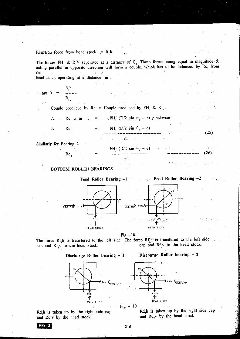
Reaction force from head stock = R,h
The forces FH, & R,V seperated at a distance of C,. These forces being equal in magnitude Br acting parallel in opposite direction will form a couple, which has to be balanced by Rc, from the head stock operating at a distance 'm'.
Rlh .'. tan 8 = ------ -- RlV
. . Couple produced by Rc, = Couple produced by FH, & RlV
Rc, x m - * . - FH, (Dl2 sin 8 , - e) clockwise
I
PC, - .. - FH, (D/2 sin 8, - e) ..................................... ------------------- (25)
m Similarly for Bearing 2
FH, (Dl2 sin 8, - e)
Rc2 - - ....................... .................... (26)
m
BOTTOM ROLLER BEARINGS
Feed Roller Bearing -1 Feed Roller Bearing -2
Rf l V R f 2 V
T .I '
I HEAD STOCK HEAD STOCK
Fig -18 The force Rf,h is transfered to the left side The force Rf2h is transfered to the left side cap and Rf,v to the head stock. cap and R4v to the head stock.
Discharge Roller bearing - 1 Discharge Roller bearing - 2 a) R\> --- -- - - - - - ----- -- - m - --- --- ---- - - - - - -- - - -
D I El 1 k A P Rd2h k A P
Rdlv RdZv
I' HEAD STOCK
T HEAD STOCK
Fig - 19 Rd,h is taken up by the right side cap Rd,h is taken up by the right and Rd,v by the head stock and Rd,v by the head stock
side cap
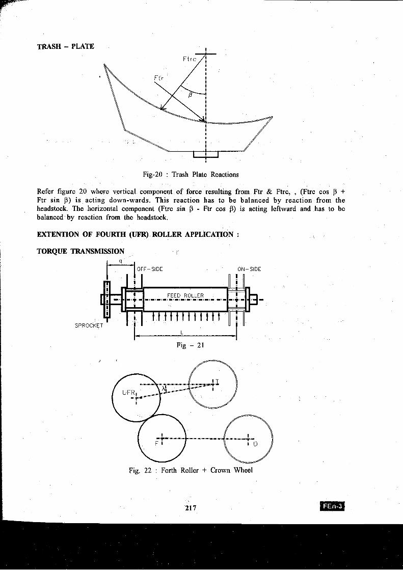
TRASH - PLATE
Fig-20 : Trash Plate Reactions
Refer figure 20 where vertical component of force resulting from Ftr & Ftrc, , (Ftrc cos j3 + Ftr sin p) is acting down-wards. This reaction has t s be balanced by reaction from the headstock. The horizontal component (Ftrc sin P - Ftr cos P) is acting leftward and has to be balanced by reaction from the headstock.
EXTENTION OF FOURTH (UFR) ROLLER APPLICATION :
TORQUE TRANSMISSION
tLi OFF-SIDE ON-SIDE
SPROCKE L
Fig - 21
Fig. 22 : Forth Roller + Crown Wheel
To c
Tfc
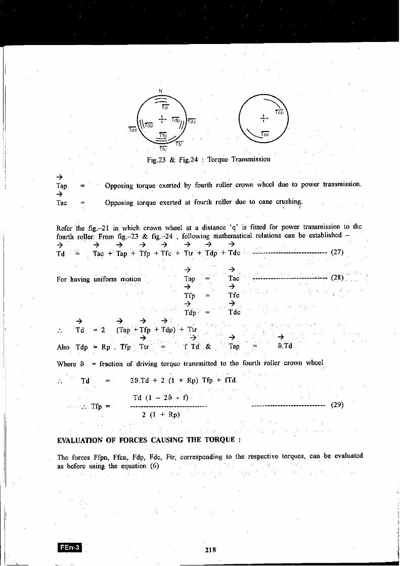
~, Fig.23 & Fig.24 : Torque Transmission
+ Tap = Opposing torque exerted by fourth roller crown wheel due to power transmission. -3
I I
I I Tac = Opposing torque exerted at fourth roller due to cane crushing. I
Refer the fig.-21 in which crown wheel at a distance 'q' is fitted for power transmission to the fourth roller. From fig.-23 & fig.-24 , following mathematical relations can be established - + 3 + + + + + + Td = Tat + Tap + Tfp + Tfc + Ttr + Tdp + Tdc --- ----- -------- P 7 )
I ' I Where 9 = fraction of driving torque transmitted to the fourth roller crown wheel
1 I
. . Td = 29.Td + 2 (1 + Rp) Tfp + f fd .
Td (1 - 2 9 - f) ,'. Tfp = .............................. ............................ (29)
2 (1 + RP)
EVALUATION OF FORCES CAUSING THE TORQUE :
+ -3 For having uniform motion Tap = Tat (28) + +
Tfp = Tfc + + Tdp* = Tdc
The forces Ffpn, Ffcn, Fdp, Fdc, Ftr, correspondillg to the respective torques, can be evaluated as before using the equation (6)
I i + + + :. Td = 2 (Tap + Tfp + Tdp) + Ttr + + + 3 Also Tdp = Rp . Tfp Ttr = f T d & Tap = 9.Td
I
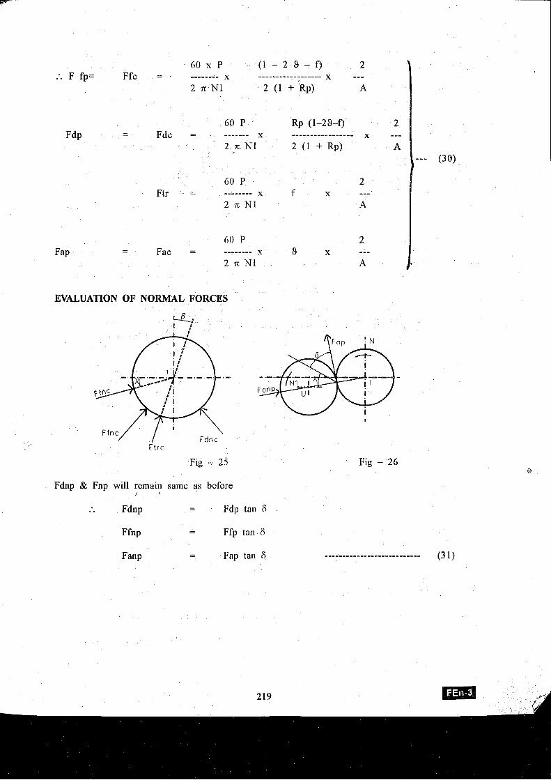
60 x P ( 1 - 2 9 - 0 2 :. F fp= Ffc = -------- x ------------------ X ---
2 n N1 2 (1 + k p ) A
60 P F ~ P - - Fdc = ------- X
2 .n N1
60 P Ftr = -------- X
2 n NI
EVALUATION OF NORMAL FORCES
F t r c
Fig - 25 Fig - 26
Fdnp & Ftlp will reinaiil same as before 2
. . Fdnp - Fdp tail 6 -
Ffilp - - Ffp tan 6
Fanp - - Fap tall 6 ........................... (3 1)
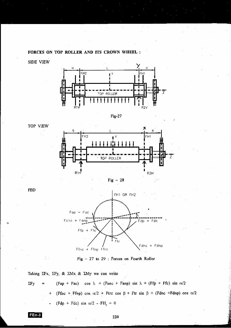
FORCES ON TOP ROLLER AND ITS CROWN WHEEL :
SIDE VIEW
TOP VIEW
Fig - 28
-,-L-,-,-,-,-#-s-#-#-
Fdp + Fdc *
Fig - 27 to 29 : Forces on Fourth Roller
Taking CFx, CFy, & CMx & CMy we can write
CFy = (Fap + Fac) cos h + (Fanc + Fanp) sin X + (Ffp + Ffc) sin a12
+ (Ffnc + Ffiip) cos a12 + Ftrc cos P + Ftr sin P + (Fdnc +Fdnp) cos a12
- (Fdp + Fdc) sin a12 - FH, = 0
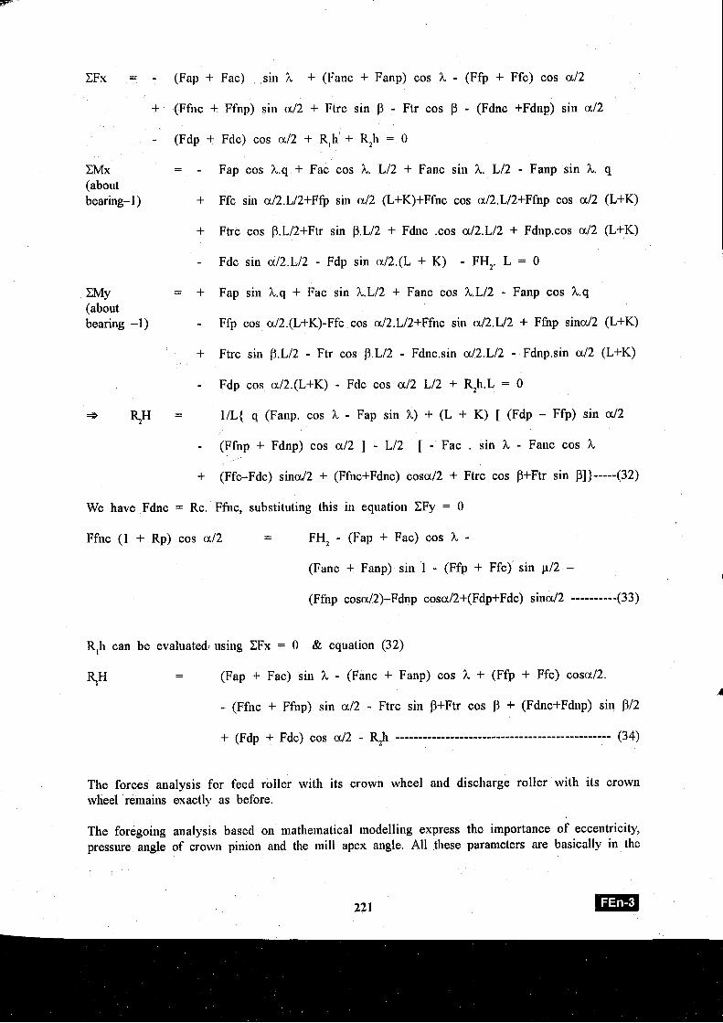
CFx = - (Fap + Fac) sin h + (Fanc + Fanp) cos h - (Ffp + Ffc) cos a /2
+ (Ffnc + Ffnp) sin a12 + Ftrc sin P - Ftr cos P - (Fdnc +Fdnp) sin a12
- (Fdp + Fdc) cos a12 + R,h + R,h = 0
m x - - - Fap cos h.q + Fac cos h. L/2 + Fanc sin h. L/2 - Fanp sin h. q (about bearing- 1 ) + Ffc sin a/2.L/2+Ffp sin a12 (L+K)+Ffnc cos a/2.L/2+Ffnp cos a12 (L+K)
+ Ftrc cos P.L/2+Ftr sin P.L/2 + Fdnc .cos a/2.L/2 + Fdnp.cos a12 (L+K)
- Fdc sin a/2.L/2 - Fdp sin a/2.(L + K) - FH,. L = 0 I m y = + Fap sin h.q + Fac sin h.L/2 + Fanc cos h.L/2 - Fanp cos h.q (about bearing -1) - Ffp cos a/2.(L+K)-Ffc cos a/2.L/2+Ffnc sin a/2.L/2 + Ffnp sind2 (L+K)
+ Ftrc sin P.L/2 - Ftr cos p.L/2 - Fdnc.sin a/2.L/2 - Fdnp.sin a12 (L+K)
- Fdp cos a/2.(L+K) - Fdc cos a12 L/2 + R$.L = 0
* .=)H = 1/L{ q (Fanp. cos h - Fap sin h) + (L + K) [ (Fdp - Ffp) sin a12
- (Ffnp + Fdnp) cos a12 ] - L/2 [ - Fac . sin h - Fanc cos h
+ (Ffc-Fdc) sina/2 + (Ffnc+Fdnc) cosa/2 + Ftrc cos P+Ftr sin PI)-----(32)
We have Fdnc = Rc. Ffnc, substituting this in equation CFy = 0 I I
Ffnc (1 + Rp) cos a12 - FH, - (Fap + Fac) cos h - i (Fanc + Fanp) sin 1 - (Ffg + Ffc)' sin y/2 - 1
R,h can be evaluated. using CFx = 0 & equation (32)
5I-i - - (Fap + Fac) sin h - (Fanc + Fanp) cos h + (Ffp + Ffc) cosa/2. A
- (Ffnc + Ffnp) sin a12 - Ftrc sin P+Ftr cos + (Fdnc+Fdnp) sin PI2
The forces analysis for feed roller with its crown wheel and discharge roller with its crown wheel remains exactly as before.
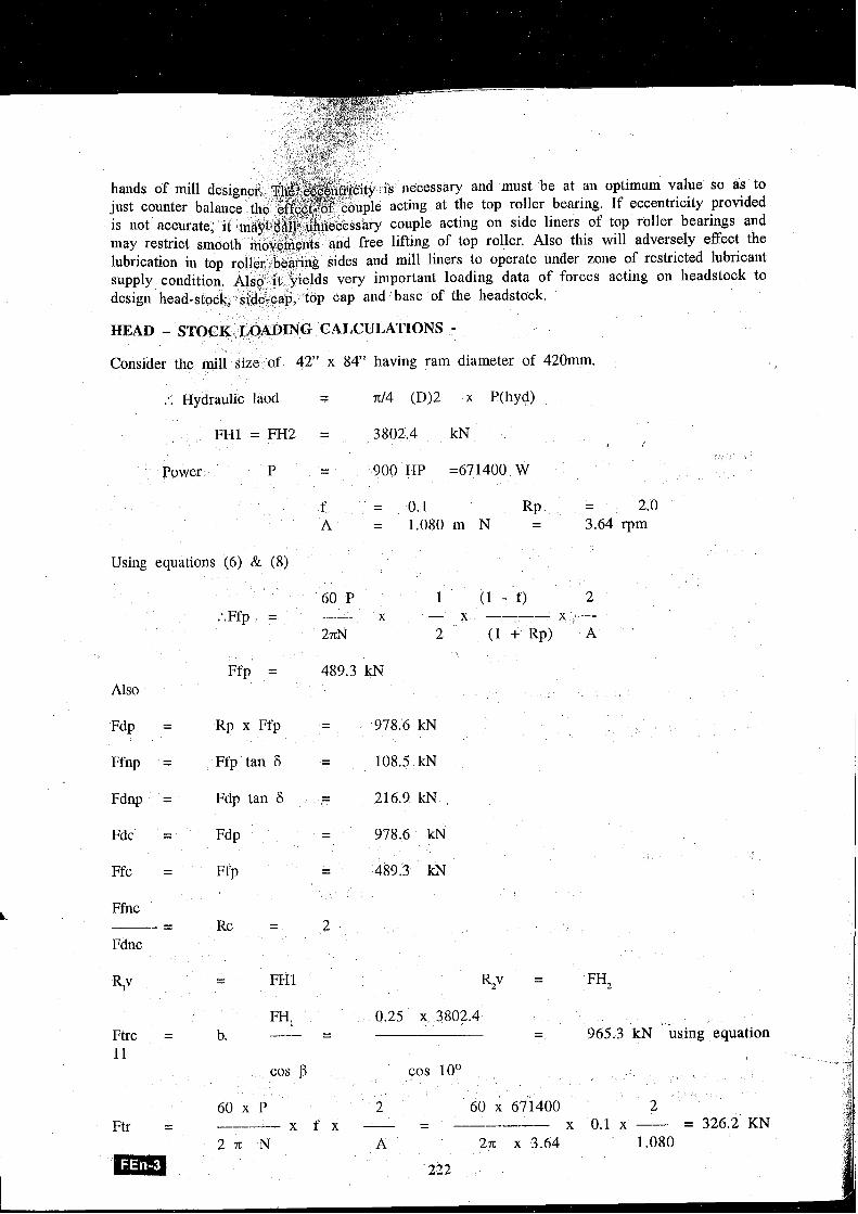
The foregoing analysis based on mathematical modelling express the importance of eccentricity, pressure angle of crown pinion and the nlill apex angle. All these parameters are basically in the
ssary and must be at an optimum value so as to at the top roller bearing. If eccentricity provided
couple acting on side liners of top roller bearings and f top roller. Also this will adversely effect the
iners to operate under zone of restricted lubricant loading data of forces acting on headstock to
f the heidstock.
HEAD - STOCK LOADING CALCULATIONS - Consider ale mill size of 42" x 84" having ram diameter of 420mm.
:. Hydraulic laod = n/4 (D)2 jr P(hyd)
FH1 = FH2 = 3802.4 kN I
Power P - 900 HP =671400 W -
f = 0.1 RP - 2.0 - A = 1.080 m N - 3.64 rpm -
Using equations (6) & (8)
60 P 1 (1 - f) 2 :.Ffp = -- x - x ---- X --
2nN 2 ( I + % ) A
Ffp = 489.3 kN Also
Fdp = Rp x Ffp - 978.6 kN -
Ffnp = Ffp tan 6 = 108.5 kN
Fdnp = Fdp tan 6 = 216.9 kN
Fdc = Fdp - 978.6 kN -
Ffc = Ff p - 489.3 kN -
L Ffnc - -- Rc
Fdnc
I FH, 0.25 x 3802.4 Ftrc = b. - 965.3 kN using equation - - - -
60 x 671400 ---- - x f x -- - x 0.1 x -- = 326.2 KN
2n x 3.64
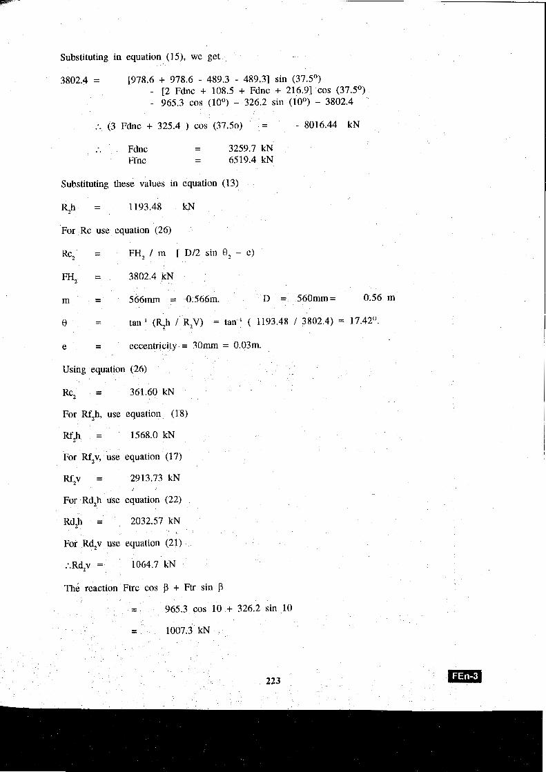
Substituting in equation (15), we get I 3802.4 = [978.6 + 978.6 - 489.3 - 489.31 sin (37.5')
- [2 Fdnc + 108.5 + Fdnc + 216.91 cos (37.5') - 965.3 cos (10') - 326.2 sin (10') - 3802.4
:. (3 Fdnc + 325.4 ) cos (37.50) = - 8016.44 kN I Fdnc - . . - 3259.7 kN Ffnc - - 6519.4 kN
Substituting these values in equation ( 13)
Rzh = 1193.48 kN
For Rc use equation (26)
Rc, = FH, / m [ Dl2 sin 8, - e)
FH, = 3802.4 kN
0 - - tan-' (R2h / RJ) = tan-' ( 1193.48 / 3802.4) = 17.42O.
e - - eccentricity = 301m = 0.03111.
Using equation (26)
Rc, = 361.60 kN
For Rf,h, - use equation (18)
Rf,h = 1568.0 kN
For Rf,v, use equation (17)
For Rd,h use equation (22)
Rd,h = 2032.57 kN
For Rd,v use equation (21)
The reaction Ftrc cos f3 + Ftr sill ) - - 965.3 cos 10 + 326.2 sin 10
- - 1007.3 kN
223
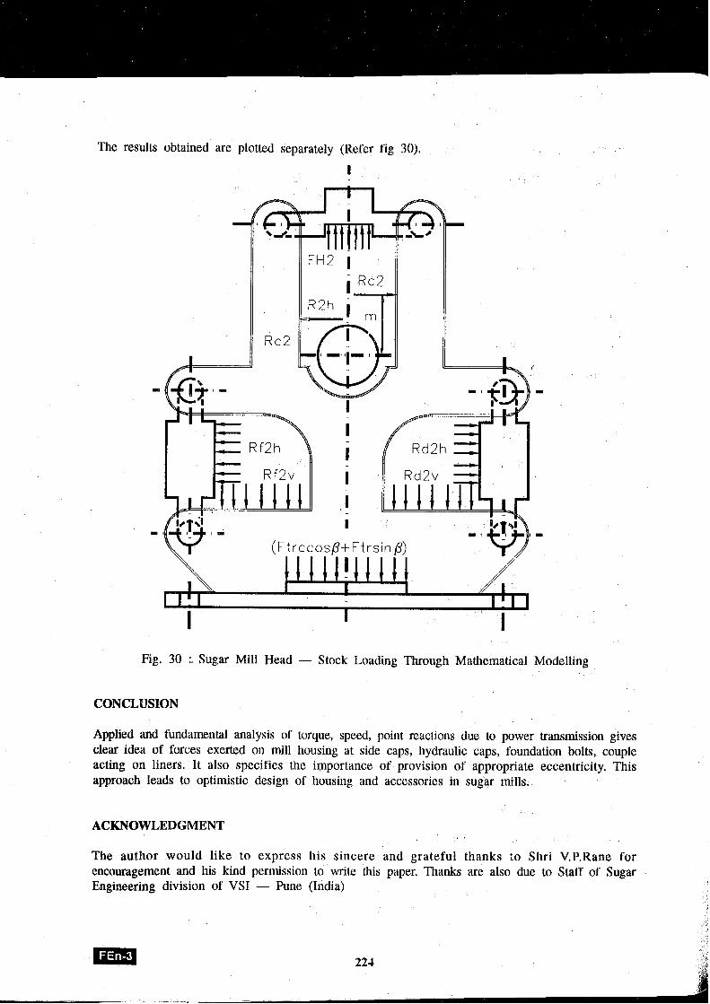
The results obtained are plotted separately (Refer fig 30).
I
Fig. 30 :. Sugar Mill Head - Stock Loading Through Mathematical Modelling
Applied and fundamental analysis of torque, speed, point reactions due to power transmission gives clear idea of forces exerted on mill housing at side caps, hydraulic caps, foundation bolts, couple acting on liners. It also specifies the ilnportance of provision of appropriate eccentricity. This approach leads to optimistic design of housing and accessories in sugar mills.
ACKNOWLEDGMENT
The author would like to express his sincere and grateful thanks to Shri V.P.Rane for encouragement and his kind permission to write this paper. Thanks are also due to Staff of Sugar Engineering division of VSI - Pune (India)
REFERENCES
G.Munoz and J.Lewinski, Analvsis of the mechanical performance of a sugar cane mill, in International Sugar Journal 1996 Volume 98 No. 1175, Page 754
George E.Dieter, Modeling & Simulation: Engineering Design Textbook page 97 to 101.
E. Hugot, Handbook of Cane Sugar Engineering, Third edition (1986), Page 162.
MOEDLO DE UN INGENIO DE CA&A DE AZUCAR
K.R. Patil Division de Ingenieria de Azucar
Instituto de azucar Vasantdada, Pune, India
El molino es una parte inherente de la mayoria de 10s sistemas de extraccion de jugo de azucar de caiia, como por ejemplo un tren de molienda, un difusor o hasta un sistema de extraccion a baja presion. De aqui que sea imperativo tener analisis detallado de las fuerzas que acthan en la vigen del molino. En maquinaria de azucar, el equipo mas intrenseco es el molino y particularmente la virgen del molino. La naturaleza de las fuerzas que acthan durante la trituracion de la (caiia es un fenomeno muy complejo y necesita analisis de parametros mecanicos como fuerza, torsion, potencia, velocidad y excentricidad.
El proposito de este estudio es presentar y analizar parametros mecanicos para tener una idea exacta acerca de la carga en varias partes de la virgen del molino. Excentricidad en inolinos es un termino el cual es confundido por ingenieros de molienda. Este estudio expresa la importancia de excentricidad dada en un molino. Cada uno de estos parametros es util en diseiio de componentes mecanicos y en el logro del diselio optimo de el molino para conseguir el funcionamiento facil durante la operation. Diseiio optimo significa la maxima extraccion de jugo con el menor consumo de energia.
Russi y Murry presentaron ecuaciones para estimar fuerzas y torques en un par de rodillos como una funcibn de las caracteristicas de la caiia de azi~car, dimension de rodillos y posicion del molino. Hugot (1986) calculo, la potencia del molino basandose en la suposicibn que la carga vertical sobre el plat0 rotatorio es un 25% de la carga vertical sobre el rodillo.
La carga basada en 10s principios y ecuaciones aplicados en este analisis han sido utilizados para el diseiio de virgen de molienda de 42" x 84" que esta operando muy satisfactoriamente en India.
Palabras Claves : Virgen del molino, modelar matemati cainente, excentricidad en molino, analisis de furzas en el molino.
K R Patil Le Sucre Division de 1'Ingenieur
Vasantdada Sugar Institut, Pune, Inde.
Un moulin de sucre est une partie inherente de la plupart des systemes de l'extraction du jus de la canne a sucre comme tandem de metier de meunier, diffuseur ou mGme systeme de l'extraction de la pression bas alors que c'est trks imperatif d'avoir l'analyse detaille de pouvoir qui agissent dans le reserve de la t8te du moulin de la canne a sucre. Dans la machinerie du sucre le materiel le plus intrinseque est moulin du sucre et en particulier la reserve de la tQte du moulin ou joue. La nature de pouvoir qui agissent pendant que la carnie Qrqse est un phenomene plus complexe colnme analyse des besoins de paranietres mecaniques comme la pouvoir, moment de rotation, faire fonctionner, vitesse et I'excentricite.
Le but de cette etude est de presenter et analyser des parametres mecaniques pour avoir l'idee exacte au sujet de chargement a plusieurs emplacements de rkserve de la tQte du moulin. L'execentricite dans les moulins est un tenne qui est confondu par les ingenieurs du moulin. Cet etude donne l'importnace d'excentricite fourni dans le moulin. Le parametre est utile dans dessin de composants mecaniques et dans accomplir le dessin optimiste du moulin pour delivrer le fonctionner lisse pendant l'operation. Les nioyens du dessin optimums d'extraction maximale de jus avec consoinmation du pouvoir la plus bas.
Russel et M u q ont presente des Bquations experimentales pour estimer le pouvoir et momnet de rotation dans une paire de pouleaux conime une fonction du characterstics de canne a sucre, dinlension de rouleaux et cadres du moulin. Hugot (1986) le pouvoir du mou;in calcule est bas6 sur la supposition que la charge verticale sur la plaque du tour est 25% de la charge verticale sur le rouleau.
Le force charger base sur les principes et equations appliquees dans cette analyse a ete utilise pour dessin de 42" x 84" reserves de la tste de la dimension du moulin et ceux-ci operent en Inde d'une maiiiere satisfaisante.
Mot-clCs: Sucre moulin t2te reserve charger, Modelage matke~natique, Excentricite